

Page 1
85.0816.00 Rev A 2004-11 (PCA 04002.12) Page 145
A-dec Service Guide, Vol. II Dental Lights
The dental light section presents details and specifications on dental lights that work
with the A-dec 500 system. These lights provide color-corrected, low UV light, and
three intensity settings. The lights are controlled from the light head, or from the
touchpad on an A-dec 500 delivery system, or assistant’s instrumentation.
This section provides information related to service, maintenance, and adjustments.
Detail on how to service the A-dec 500 and 6300 dental lights and troubleshooting for
specific problems is presented. For information on service parts, see the Genuine A-dec
Service Parts Catalog or contact A-dec customer service.
Page 2

Page 146 85.0816.00 Rev A 2004-11 (PCA 04002.12)
Specifications A-dec Service Guide, Vol. II
Dental Light Specifications
Electrical
100 VAC, 110-120 VAC, or 220-240V AC (Post-, Ceiling-, Wall-, Preference- and Track-mounted Lights)
Operating wattage: 96 watts
Heat output: 325 BTU/hour
Lamp
Lamp: Quartz Xenon Halogen, single-end prongs, extended life
Lamp rating: 24 V/150 watts
Color temperature: 5000 Kelvin
Light pattern: 3.3" x 6.3" at 27.6" (85 mm x 160 mm at 700 mm)
Nominal Light Intensity
Composite: 8,000 lux (743 fc)
Medium: 20,000 lux (1858 fc)
High: 24,000 lux (2230 fc)
Specifications are subject to change without notice.
Page 3

85.0816.00 Rev A 2004-11 (PCA 04002.12) Page 147
A-dec Service Guide, Vol. II Dental Light Features
On/Off Functions
The dental light has additional features when used with an A-dec 500 system.
On/Off Switch
An On/Off switch is located on the touchpad. Press and hold the Dental Light button, to turn off the dental light.
Auto On/Off Function
The dental light will turn On, when the A-dec 500 chair reaches programmed positions 1, 2, or 3.The dental light turns Off, as soon as
Position O is pressed. When Position 3 is used as a last position/return function, the light will turn Off when Position 3 is pressed the first
time. It will turn On after the button is pressed a second time when it reaches the last position.
The Auto On/Off feature is disabled by pressing and holding the Program button and the Dental Light button together for three seconds.
One beep confirms that the auto On/Off feature is disabled. To enable the Auto On/Off feature, repeat. Three beeps confirms that Auto On/Off
is enabled.
Three-Way Switch
The dental light button on the touchpad works as a three-way switch with the On/Off switch, allowing the light to turn On or Off from the
touchpad or the On/Off switch.
Intensity Switches
There are three intensity settings for the A-dec 571 and 6300 dental lights. Move the intensity switch to toggle between high, medium, or
composite settings.
Press Dental Light on the A-dec 500 touchpad to toggle between intensity settings. The dental light can toggle between composite and high
intensity settings or composite and medium intensity settings, depending on the location of the dental light intensity switch. The indicator light
next to the touchpad button flashes when in the composite setting mode.
Page 4
Page 148 85.0816.00 Rev A 2004-11 (PCA 04002.12)
Circuit Breakers A-dec Service Guide, Vol. II
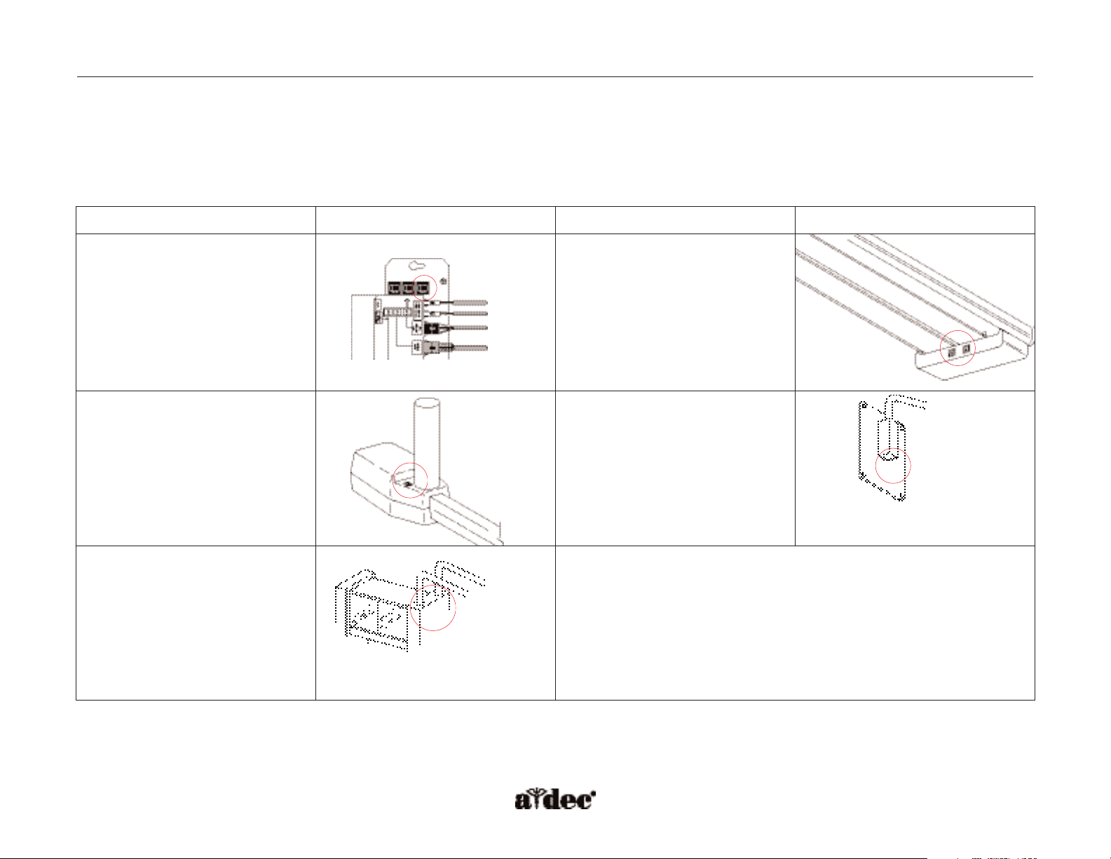
How to Locate Circuit Breakers
A circuit breaker will interrupt the flow of electricity under abnormal conditions. If the circuit breaker should trip, inspect the wiring to ensure
there are no shorts, and reset the circuit breaker by flipping the switch.
Light Name Circuit Breaker Location Light Name Circuit Breaker Location
A-dec 571
NOTE: The circuit breaker
for the A-dec 571 light
is located on the chair
power supply inside
the chair motor
pump area.
Track
Ceiling-mounted Wall-mounted
Preference-mounted
Page 5
85.0816.00 Rev A 2004-11 (PCA 04002.12) Page 149
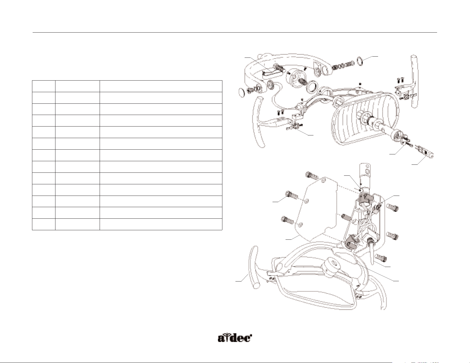
Light Head
(P/N 28.1007.00)
A-dec Service Guide, Vol. II Illustrated Parts
Item #
Part Number
Description
1
28.1004.00
Lamp and holder
2
041.179.01
Lamp
3
75.0084.00
Holder only
4
28.1536.00
Light yoke plug
5
90.0463.01
Lamp socket kit
6
28.1012.00
Shield bracket assembly, Pkg 2
7
28.1001.00
Pivot stop
8
43.0054.00
Intensity switch kit
9
90.1039.00
On/Off switch kit
10
28.1464.01 Switch housing kit
11
90.0367.01 Light handle kit
12
002.135.00 Screw
3
2
5
6
7
8
9
10
1
4
Figure 102. Identification of the light head components.
12
11
Page 6
Page 150 85.0816.00 Rev A 2004-11 (PCA 04002.12)
Wiring and DCS Connections A-dec Service Guide, Vol. II
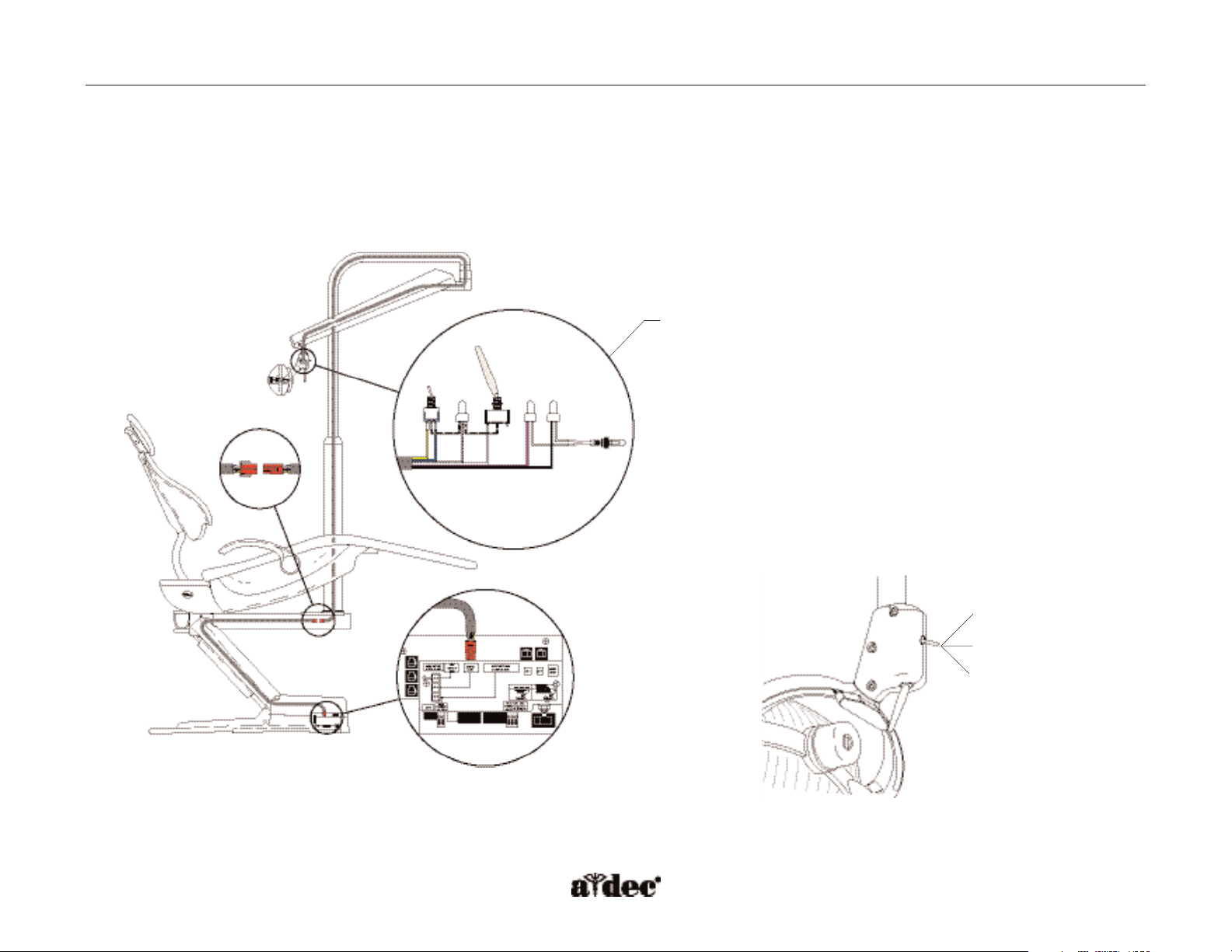
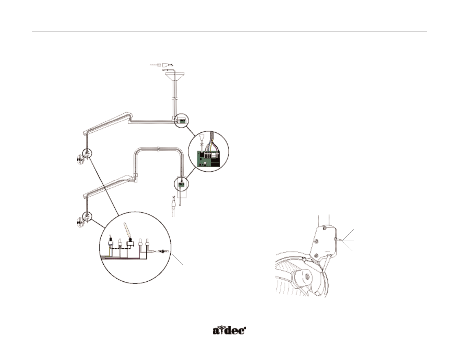
How to Identify Intensity Switch Connections and Data Line Flow
The three-position intensity switch is used to select light intensity at one of three settings: high, medium, or composite.
The replacement kit for the intensity switch is P/N 43.0054.00.
A-dec 571 Light
Figure 103. A-dec 571 light switch connections. (A) switch and lamp connections
A
Figure 104. Light intensity setting. (A) high; (B) medium;
(C) composite
A
C
B
Page 7
85.0816.00 Rev A 2004-11 (PCA 04002.12) Page 151
A-dec Service Guide, Vol. II Wiring and DCS Connections
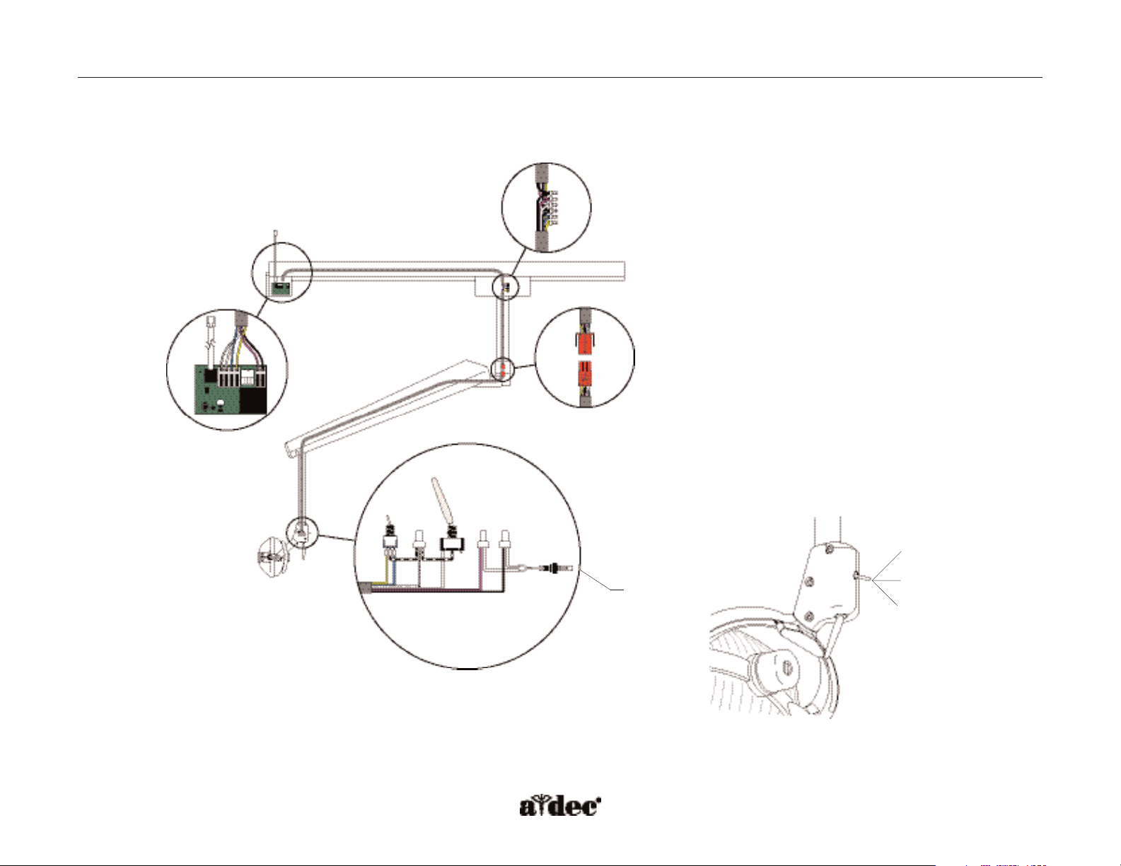
Ceiling-, Wall- and Preference-mount Lights
Figure 105. A-dec 6300 ceiling and wall-mounted light switch connections and
data line. (A) switch and lamp connections
To chair circuit board
To chair circuit board
A
Figure 106. Light intensity setting. (A) high; (B) medium;
(C) composite
A
C
B
6300 light circuit board
Page 8
Page 152 85.0816.00 Rev A 2004-11 (PCA 04002.12)
Wiring and DCS Connections A-dec Service Guide, Vol. II
Track Light
Figure 107. A-dec 6300 track light switch connections and data line. (A) switch
and lamp connections
To chair circuit board
A
Figure 108. Light intensity setting. (A) high; (B) medium;
(C) composite
A
C
B
6300 light circuit board
Page 9

85.0816.00 Rev A 2004-11 (PCA 04002.12) Page 153
A-dec Service Guide, Vol. II Dental Light Wiring
Power Cable
(P/N 28.1584.00)
NOTE: If Pin 3 and Pin 4 are 5 VDC, then
the output voltage on Pin 5 is
medium intensity.
Pin
Voltage
Wire
1
0 VDC (circuit ground)
Black/White
2
0 VAC
Black
3
5 VDC = high or medium
0 VDC = composite
Yellow
(composite)
4
5 VDC = medium or composite
0 VDC = high out
Blue
(high)
5
17/16/12.1 VAC
Violet
6
5 VDC = On/Off toggle = open
0 VDC = On/Off toggle = closed
White
(On/Off)
Page 10

Page 154 85.0816.00 Rev A 2004-11 (PCA 04002.12)
Dental Light Wiring A-dec Service Guide, Vol. II
How to Wire the Transformer
100 VAC Transformer
(P/N 28.1588.00)
All voltages of transformers are the same part number but wired differently for each voltage.
Page 11

85.0816.00 Rev A 2004-11 (PCA 04002.12) Page 155
A-dec Service Guide, Vol. II Dental Light Wiring
110-120 VAC Transformer
(P/N 28.1588.00)
220-240 VAC Transformer
(P/N 28.1588.00)
Page 12

Page 156 85.0816.00 Rev A 2004-11 (PCA 04002.12)
Dental Light Circuit Boards A-dec Service Guide, Vol. II
How to Identify Circuit Board Components
A-dec 511 Chair Circuit Board (P/N 90.1072.00) for A-dec 571 Lights
Function K1 (DS8) K6 (DS7) Output
Off Off Off 0 VAC
High intensity On Off 17 VAC
Composite intensity Off On 12 VAC
Medium intensity On On 16 VAC
Item # Description
1
P7, P8, P9 - Data line ports
2
DS4 - Stop switch LED (limit switch) and
P10 connector
3
DS5 - Back potentiometer LED and P1 connector
4
DS6 - Base potentiometer LED and P2 connector
5
P5 - Footswitch connector
6
P3 - Test points
7
DS12 - Base down LED and relay
8
DS11 - Base up LED and relay
9
DS10 - Back down LED and relay
10
DS9 - Back up LED and relay
11
DS1 - AC power LED
12
DS2 - Status LED
13
DS3 - Data LED
14
DS13 - Chair lockout LED and terminal strip J1
15
J2 - Ø VAC terminal strip (output)
16
J2 - 24 VAC terminal strip (output)
17
P4 - Input power and dental light connector
18
J3 - Vacuum relay output terminal strip
19
P11 - Pump motor and solenoid connector
20
DS8 - Dental light relay
21
DS7 - Dental light relay
Page 13

85.0816.00 Rev A 2004-11 (PCA 04002.12) Page 157
A-dec Service Guide, Vol. II Dental Light Circuit Boards
Figure 109. A-dec 511 chair circuit board components.
1
11
12
13
14
4
3
5
6
7
8
9
10
21
18
16
15
20
2
17
19
Page 14

Page 158 85.0816.00 Rev A 2004-11 (PCA 04002.12)
Light Circuit Boards A-dec Service Guide, Vol. II
LED Identification
LED Status Description
DS1 - AC power LED Off
Green, steady
No 24 VAC power, tripped circuit breaker, power supply turned off,
no line voltage
24 VAC at the terminal strip
DS2 - Status LED Off
Green, steady
System is not functioning, no power or circuit board has failed
Normal operation
DS3 - Data LED Off
Green, steady
Green, blinking
No DCS communication, not connected to the DCS, or DCS has failed
Detects active DCS
Valid DCS message
DS4 - Chair limit switch Off
Red
Closed, (normal)
Open, (activate)
DS13 - Chair lockout Off
Red
Open, (normal)
Closed, (activate)
DS5 + DS6 - Chair potentiometers Off Potentiometer:
• Not connected or bad connection
•Moving in wrong direction
•Limited range of motion, or
• Cable is not on wheel.
Yellow, steady Normal operation
Yellow, fast blink Upper end of travel
DS9, DS10, DS11, DS12 - Chair
relay LEDs
Off
On
Relay is off
Relay is on
DS7, DS8 - Dental light relay LEDs Off
On
Relay is off
Relay is on
DS14 - Vacuum relay LED Off
On
Relay is off
Relay is on
Page 15

85.0816.00 Rev A 2004-11 (PCA 04002.12) Page 159
A-dec Service Guide, Vol. II Light Circuit Boards
Function K1 (DS4) K2 (DS5) Output
Off Off Off 0 VAC
High intensity On Off 17 VAC
Composite intensity Off On 12 VAC
Medium intensity On On 16 VAC
Figure 110. 6300 dental light relay circuit board.
6300 Dental Light Relay Circuit Board
(P/N 28.1577.00)
The 6300 dental lights are controlled by the dental light circuit board located in the dental light transformer housing.
Item # Description
1
DS1 - AC power LED
2
DS2 - Status LED
3
DS3 - Data LED
4
DS4 - Dental light relay
5
DS5 - Dental light relay
6
P1 - Input power
7
P2 - Data line port (DCS)
8
J1 - Toggle switch inputs
9
J2 - Dental light output power
68
9
7
321
4 5
Page 16

Page 160 85.0816.00 Rev A 2004-11 (PCA 04002.12)
Light Circuit Board LED Identification
LED Status Description
DS1 - AC power LED Off
Green, steady
No 24 VAC power, tripped circuit breaker, power supply turned off,
no line voltage
24 VAC at the terminal strip
DS2 - Status LED Off
Green, steady
System is not functioning, no power or circuit board has failed
Normal operation
DS3 - Data LED Off
Green, steady
Green, blinking
No DCS communication, not connected to the DCS, or DCS has failed
Detects active DCS
Valid DCS message
DS4, DS5 - Dental light relay LEDs DS4 DS5
Off Off
On Off
Off On
On On
Off
High
Composite
Medium
Circuit Boards A-dec Service Guide, Vol. II
Page 17

85.0816.00 Rev A 2004-11 (PCA 04002.12) Page 161
A-dec Service Guide, Vol. II Light Adjustments
How to Adjust the Dental Light
The light is preset for proper illumination at 27.6 inches (700 mm) from the black nose piece to the oral cavity.
The light has a focal adjustment range between 18" and 31"(460 mm and 790 mm).
Focus
1. Place a white towel over the chair headrest to represent the oral cavity.
2. Position the light head at the distance normally used when working in the oral cavity (select a distance representative of most procedures).
3. Turn the light ON.
4. Use a large screwdriver to turn the focus adjusting screw until the light, within the borders of the light pattern, is most uniform.
Page 18

Page 162 85.0816.00 Rev A 2004-11 (PCA 04002.12)
Dental Light Adjustments A-dec Service Guide, Vol. II
Light Head Rotation (Horizontal)
The light head needs adjusting if it is difficult to position, moves too easily, or tends to slip out
of position.
Left/Right Rotation
•Turn the adjustment screws beginning with the screw at the top of the switch housing.
• Light head moves too easily, or tends to drift out of position.
Increase the tension by turning the screws clockwise.
• Light is difficult to move.
Loosen the tension by turning the screws counterclockwise.
Figure 111. Left/right rotation.
Figure 112. Rotation adjustment.
(A) left/right rotation tension screw;
(B) diagonal rotation tension screw
A
B
Page 19

85.0816.00 Rev A 2004-11 (PCA 04002.12) Page 163
A-dec Service Guide, Vol. II Dental Light Adjustments
Diagonal Rotation (Third Axis)
Turn the adjustment screws, beginning with the screw at the bottom of the switch housing.
• Light head moves too easily, or tends to drift out of position, increase the tension by
turning the screws clockwise.
• Light head is difficult to move.
Loosen the tension by turning the screw counterclockwise.
•Tighten the adjustment screw until they are tight to eliminate all movement in the diagonal axis.
Figure 113. Diagonal axis rotation.
Page 20

Page 164 85.0816.00 Rev A 2004-11 (PCA 04002.12)
Light Adjustments A-dec Service Guide, Vol. II
Up/Down Rotation (Vertical)
This adjustment only needs to be made to one side of the light head.
1. Loosen the setscrew.
2. Remove the light yoke plug.
3. Use a large flat-blade screwdriver to turn the adjustment screw under the light yoke plug.
• Light head moves too easily, or tends to drift out of position.
Increase the tension by turning the screw clockwise.
• Light head is difficult to move.
Loosen the tension by turning the screw counterclockwise.
• Retighten the setscrew, and reinstall the light yoke plug.
Figure 114. Up/down rotation.
Figure 115. Up/down rotation adjustment.
(A) setscrew; (B) light yoke plug
A
B
Page 21

85.0816.00 Rev A 2004-11 (PCA 04002.12) Page 165
A-dec Service Guide, Vol. II Dental Light Adjustments
How to Adjust the Flexarm
Remove the screw and cover from the flexarm.Turn the tension adjustment nut inside the flexarm using a 1/2" open end wrench. Tighten the nut
by turning it clockwise, if the flexarm moves too easily, or tends to drift down by itself. Loosen the nut by turning it counterclockwise, if the arm
drifts up.
NOTE:A travel stop limit kit (P/N 90.1044.00) must be installed to limit the upward and downward motion of the flexarm.
Figure 116. Flexarm adjustments. (A) adjustment nut
A
Loosen
Tighten
Page 22

Page 166 85.0816.00 Rev A 2004-11 (PCA 04002.12)
Dental Light Maintenance A-dec Service Guide, Vol. II
How to Maintain the Dental Light
Light Shield Cleaning
1. Turn Off the dental light.
WARNING:To avoid personal injury, be sure that the light has cooled before cleaning it.
2. Release the toggles on either side of the light to remove the light shield.
3. Use a 100% cotton gauze pad or a soft, dry, lint-free cloth to clean the light shield
and reflector.
If necessary, soak the pad or cloth with water or with a diluted solution of mild dish washing
liquid before cleaning. Make certain no residue remains on the surface.
Do not use abrasives or chlorine (such as household bleach) on the surface of the reflector.
These can damage or discolor the reflector surface, impairing the effectiveness.
CAUTION: Do not rub heavily, clean the light shield when it is hot, or soak the shield
assembly in cleaning solution. Doing so may damage the shield assembly
components. Clean the light shield only as instructed.
Figure 117. Light shield cleaning. (A) toggle;
(B) light shield; (C) reflector
A
B
C
Page 23

85.0816.00 Rev A 2004-11 (PCA 04002.12) Page 167
A-dec Service Guide, Vol. II Dental Lamp Replacement
Lamp Replacement
Pull the spare lamp holder from the light head. Remove the lamp from the holder, but do not remove
the outer wrapper. Finger oils can affect light performance and severely limit lamp life. If lamp is
inadvertently touched, gently clean it with cotton dampened with isopropyl or
ethyl alcohol.
WARNING:To avoid burning fingers, allow the lamp to cool before removing. Never operate the
light with the light shield removed. The clear shield minimizes UV light output. The
light shield is also protection in the unlikely event that the lamp shatters.
1. Turn Off the light, and allow the light to cool.
2. Release the toggles on the light shield and set the shield aside.
3. Use a gauze pad or cloth to protect fingers. Carefully pull the old lamp from its socket
and discard.
4. Hold the new lamp in its outer wrapper with the pins facing away, and carefully insert it in
the socket. The lamp base is fragile and can break under excess pressure.
5. Remove and discard the outer wrapper, reinstall the light shield, and secure with
the toggles.
6. Verify the operation of the light by turning it on and operating it at each intensity setting.
CAUTION: Use of halogen bulbs other than A-dec P/N 041.179.01 (OSRAM HLX 64640,
150W 24V) may result in damage to the bulb socket.
Figure 119. Insert lamp. (A) new lamp;
(B) outer wrapper
Figure 118. Remove lamp from holder.
(A) lamp; (B) holder
B
A
A
B
Page 24

Page 168 85.0816.00 Rev A 2004-11 (PCA 04002.12)
Dental Light Troubleshooting A-dec Service Guide, Vol. II
How to Troubleshoot the Dental Light
Tips and troubleshooting information are listed in the table to assist in diagnosing dental light problems.
This table is not intended to cover every situation, but does include the most common problems that may
be encountered.
Problem Possible Cause Action
Light head is loose or difficult to position Rotation tension screws are too loose or tight Adjust the appropriate axis tension
Flexarm drifts Tension adjustment nut inside the flexarm is too
loose or tight
Adjust the flexarm counterbalance
Track light trolley drifts Track is not level Use wedges to level the track light ceiling pallet (P/N 017.017.00)
Track trolley light bounces back when
pushed to the end of the track
Power cable is hanging up inside the track Check power cable in track for proper routing
Light intensity is dim, inconsistent, or the
color is distorted
Reflector or light shield may be damaged, the
intensity switch may be in the wrong position
1. Clean the reflector and light shield.
2. Check the intensity switch position.
3. Check the line voltage at the wall.
4. Check the light shield for severe abrasions, and replace if necessary.
5. Check the color of the lamp, replace if discolored.
Unsatisfactory light pattern Light is out of focus, reflector or light shield may
be damaged
1. Focus the light.
2. Check the light shield for severe abrasions, and replace if necessary.
3. Clean the reflector and light shield.
Light does not function No power to the light, defective socket, lamp has
failed, or no power to the transformer
Verify the dental light is connected to a working power source. Ensure all
electrical switches are in the On position.Verify the power supply air-electric
switch has sufficient air pressure to close. Check for loose connections. Replace
the socket, replace the lamp.
One or more intensity positions do
not function
Tr ansformer is not supplying one or more voltages Check for loose connections at the transformer. Measure the transformer
output voltages. Check the power cable for continuity.
Page 25

85.0816.00 Rev A 2004-11 (PCA 04002.12) Page 169
A-dec Service Guide, Vol. II Conclusion
Thank You
Thank you for taking time to use the A-dec Service Guide,Volume II.We would appreciate any feedback or comments you have about this document.
Please mail, email, or phone us with your input. You can reach us at:
A-dec Inc.
Technical Communications Department
2601 Crestview Drive
Newberg, OR 97132
Reach us by phone: 1.800.547.1883
email: techcomm@a-dec.com
website: www.a-dec.biz
 Loading...