

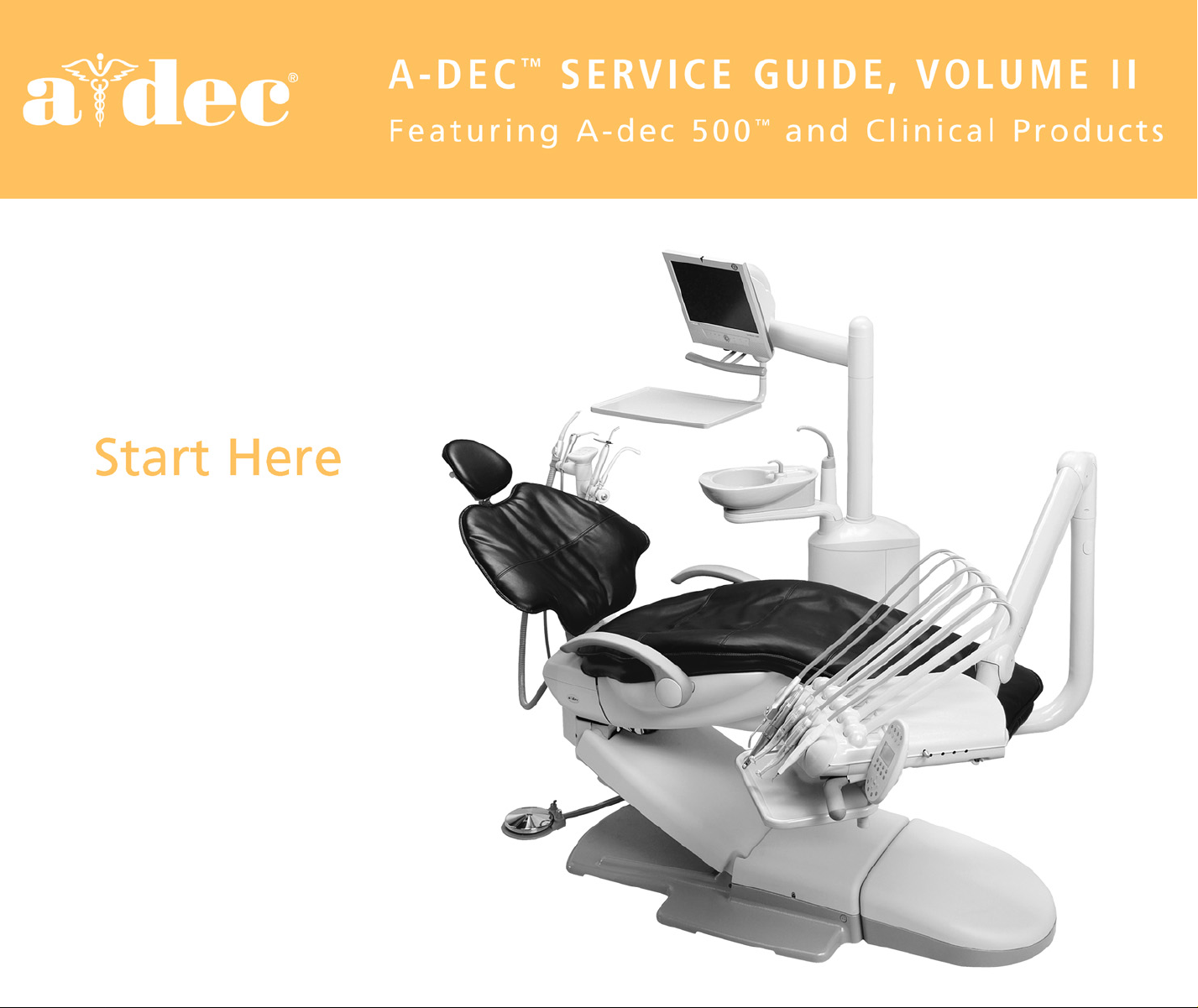
Page 1
Page 2

Welcome to the online A-dec 500™and
Clinical Products service guide 2004 Edition
How to navigate
• About this document
• Copyright and trademarks
• Agency information
• Contacting customer service
• Warranty/return merchandise
• Table of contents
Titles in the table of contents and on this page are linked to the appropriate
sections. Use the links to jump to the desired section of the service guide.
The A-dec logo found at the bottom of the pages will take you back to the table of
contents.You can also use the arrow buttons in the menu bar to move forward or
backward through a section.
Page 3

Page 4

85.0816.00 Rev A 2004-11 (PCA 04002.12) Page iii
Copyright
©2004 A-dec Inc. All Rights Reserved.
2601 Crestview Drive, Newberg, OR 97132, USA Printed in USA.
A-dec Inc. makes no warranty of any kind with regard to the content in this document, including but not
limited to, the implied warranties of merchantability and fitness for a particular purpose. A-dec Inc. shall
not be held liable for any errors contained herein or any consequential or other damages concerning the
furnishing, performance or use of this material.The information in this document is subject to change
without notice. If you find any problems with this document, please report them to us in writing.
A-dec Inc. does not warrant that this document is error-free.
All other non A-dec products or services mentioned in this document are covered by the trademarks,
service marks, or product names designated by the companies marketing those products.
Trademarks
A-dec logo, Cascade, Cascade Master Series, Century Plus, Continental, Decade, Performer, Preference,
Preference Collection, and Radius are registered trademarks in the U.S. Patent and Trademark office.
A-dec, A-dec 500, ICX, and Preference ICC are also trademarks of A-dec Inc.
Page 5
Page iv 85.0816.00 Rev A 2004-11 (PCA 04002.12)
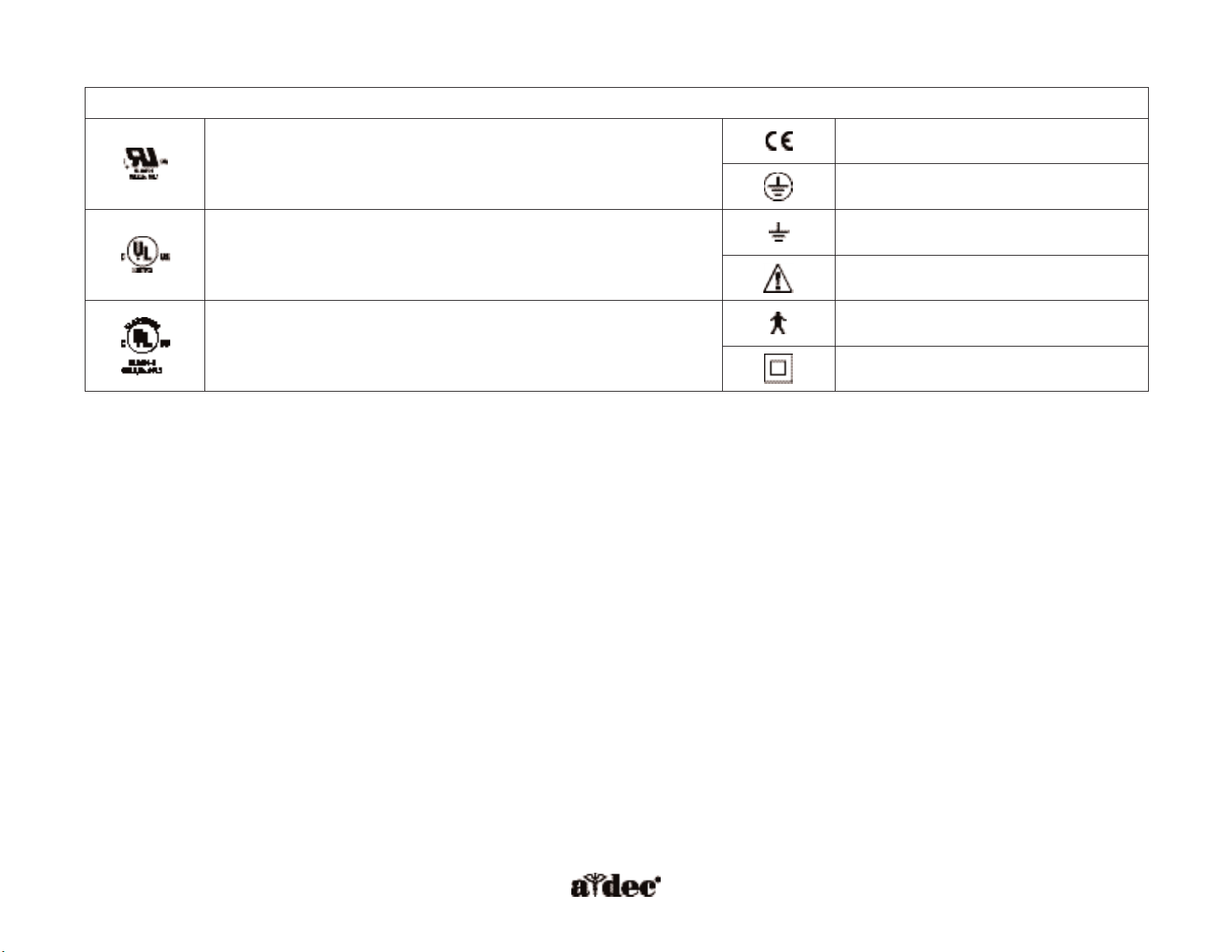
Identification of Symbols
Recognized by Underwriters Laboratories Inc.® with respect to electric shock, fire
and mechanical hazards only in accordance with UL 2601-1. Recognized with
respect to electric shock, fire, mechanical and other specified hazards only in
accordance with CAN/CSA C22.2, No. 601.1
Conforms to European Directives
(refer to Declaration Statement)
Protective earth (ground)
UL listed to US (UL 544) and Canadian (CAN/CSA C22.2, No. 125) safety standards
Functional earth (ground)
Attention, consult accompanying documents
Classified by Underwriters Laboratories Inc. with respect to electric shock, fire and
mechanical hazards only in accordance with UL 2601-1. Classified with respect to
electric shock, fire, mechanical and other specified hazards only in accordance with
CAN/CSA C22.2, No. 601.1
Type B applied part
Class II equipment
Classification of Equipment (EN 60601-1)
Types of Shock Protection:
Class I Equipment (Dental Chairs, Dental Lights, & Power Supplies)
Class II Equipment (Chair, Wall, & Cart-Mounted Delivery Systems)
Degree of Shock Protection:
Type B Applied Part (Delivery Systems Only)
Degree of Protection Against Water Ingress:
Ordinary Equipment (All products)
Mode of Operation:
Continuous Operation (All models except Dental Chairs)
Continuous Operation with Intermittent Loading (Dental Chairs -5% duty cycle)
Environmental
For Storage: All equipment
Temperature: -40°C to 70°C
-40°F to 158°F
Relative Humidity: 95% maximum
For Operation:
Temperature: 10°C to 40°C
50°F to 104°F
Relative Humidity: 95% maximum
Electromagnetic Compatibility
This equipment has been tested and found to comply with the limits for medical devices
in EN60601-1-2. These limits are designed to provide reasonable protection against
harmful interference in a typical medical installation. Contact A-dec Customer Service, if
you have any questions.
Flammable Gasses
Not suitable for use in the presence of a flammable anesthetic mixture with air, oxygen
or nitrous oxide, where such gasses may accumulate in concentration (closed space).
Page 6

85.0816.00 Rev A 2004-11 (PCA 04002.12) Page v
Warranty
A-dec warrants its products against defects in material or workmanship for one year from time of delivery.
A-dec’s sole obligation under the warranty is to provide parts for the repair, or at its option, to provide the
replacement product (excluding labor). The buyer shall have no other remedy. All special, incidental, and
coincidental damages are excluded.
Written notice of breach of warranty must be given to A-dec within the warranty period. The warranty does
not cover damage resulting from improper installation or maintenance, accident or misuse. The warranty
does not cover damage resulting from the use of cleaning, disinfecting or sterilization chemicals and
processes. The warranty also does not cover light bulbs. Failure to follow instructions provided in the
A-dec Owner’s Guide (operation and maintenance instructions) may void the warranty.
A-dec warrants A-dec dental chair cylinders, both lift and tilt, for ten years from the date of purchase of the
chair or the cylinder.This warranty is retroactive to A-dec chair cylinders already in the field. The warranty
covers chair cylinders A-dec finds to have manufacturing related irregularities. Stool cylinders are covered
under A-dec‘s one year warranty.
No other warranties as to merchantability or otherwise are made.
Return Merchandise
U.S. and Canadian dealers wishing to return overstock (unopened) merchandise to A-dec for credit
consideration must include a copy of the original invoice number. A return authorization form from an
A-dec Territory Manager must be included with serial numbered equipment or A-dec/W&H handpieces.
A 15% restocking fee will be assessed.
Merchandise that cannot be returned for credit includes parts assembled to the dental unit, chair, light, or
cabinet; obsolete parts; and specials. Preference Collection dental furniture cannot be returned for credit.
In the case of a defective warranty item, a copy of the replacement invoice, serial number of the unit under
which it was replaced, and a description of the symptoms of the defect must be returned with the part to:
A-dec Inc. 2601 Crestview Drive, Newberg, Oregon 97132, USA.
Page 7

Page vi 85.0816.00 Rev A 2004-11 (PCA 04002.12)
Page 8

A-dec Service Guide, Vol. II Contents
85.0816.00 Rev A 2004-11 (PCA 04002.12) Page vii
General Information
About this document . . . . . . . . . . . . . . . . . . . . . . . . . . . . . . . . . . . . . . . . . . . . . . . . . . . . . . . . . . . . . . . . . . .xvii
Getting support . . . . . . . . . . . . . . . . . . . . . . . . . . . . . . . . . . . . . . . . . . . . . . . . . . . . . . . . . . . . . . . . . . . . . . .xviii
Information sources . . . . . . . . . . . . . . . . . . . . . . . . . . . . . . . . . . . . . . . . . . . . . . . . . . . . . . . . . . . . . . . . . . . .xix
Serial numbers . . . . . . . . . . . . . . . . . . . . . . . . . . . . . . . . . . . . . . . . . . . . . . . . . . . . . . . . . . . . . . . . . . . . . . . . .xx
Service tools . . . . . . . . . . . . . . . . . . . . . . . . . . . . . . . . . . . . . . . . . . . . . . . . . . . . . . . . . . . . . . . . . . . . . . . . .xxiii
A-dec tubing . . . . . . . . . . . . . . . . . . . . . . . . . . . . . . . . . . . . . . . . . . . . . . . . . . . . . . . . . . . . . . . . . . . . . . . . . .xxv
Handpiece tubing . . . . . . . . . . . . . . . . . . . . . . . . . . . . . . . . . . . . . . . . . . . . . . . . . . . . . . . . . . . . . . . . . . . .xxviii
Quick-connect fittings . . . . . . . . . . . . . . . . . . . . . . . . . . . . . . . . . . . . . . . . . . . . . . . . . . . . . . . . . . . . . . . . .xxix
Data communication system (DCS) . . . . . . . . . . . . . . . . . . . . . . . . . . . . . . . . . . . . . . . . . . . . . . . . . . . . . . .xxx
Programming
Chair Programming
Position programming . . . . . . . . . . . . . . . . . . . . . . . . . . . . . . . . . . . . . . . . . . . . . . . . . . . . . . . . . . . . . . . . . . . .2
Position 3 (X-ray/Rinse) . . . . . . . . . . . . . . . . . . . . . . . . . . . . . . . . . . . . . . . . . . . . . . . . . . . . . . . . . . . . . . . . . .2
Footswitch icons . . . . . . . . . . . . . . . . . . . . . . . . . . . . . . . . . . . . . . . . . . . . . . . . . . . . . . . . . . . . . . . . . . . . . . . .2
Delivery System Programming
Touchpad icons . . . . . . . . . . . . . . . . . . . . . . . . . . . . . . . . . . . . . . . . . . . . . . . . . . . . . . . . . . . . . . . . . . . . . . . . .3
Dual operator mode . . . . . . . . . . . . . . . . . . . . . . . . . . . . . . . . . . . . . . . . . . . . . . . . . . . . . . . . . . . . . . . . . . . . .4
Handpiece configuration for deluxe touchpad . . . . . . . . . . . . . . . . . . . . . . . . . . . . . . . . . . . . . . . . . . . . . . . .4
Programming memory . . . . . . . . . . . . . . . . . . . . . . . . . . . . . . . . . . . . . . . . . . . . . . . . . . . . . . . . . . . . . . . . . . .4
Electric micromotor . . . . . . . . . . . . . . . . . . . . . . . . . . . . . . . . . . . . . . . . . . . . . . . . . . . . . . . . . . . . . . . . . . . . . .4
Scaler . . . . . . . . . . . . . . . . . . . . . . . . . . . . . . . . . . . . . . . . . . . . . . . . . . . . . . . . . . . . . . . . . . . . . . . . . . . . . . . . .5
Cuspidor and Light Programming
Cup fill and bowl rinse functions . . . . . . . . . . . . . . . . . . . . . . . . . . . . . . . . . . . . . . . . . . . . . . . . . . . . . . . . . . .6
Dental light (Auto On/Off) . . . . . . . . . . . . . . . . . . . . . . . . . . . . . . . . . . . . . . . . . . . . . . . . . . . . . . . . . . . . . . .6
Page 9

Contents A-dec Service Guide, Vol. II
Page viii 85.0816.00 Rev A 2004-11 (PCA 04002.12)
LED Troubleshooting Quick Start
LED troubleshooting . . . . . . . . . . . . . . . . . . . . . . . . . . . . . . . . . . . . . . . . . . . . . . . . . . . . . . . . . . . . . . . . . . . . .7
Touchpad Programming
Factory preset functions . . . . . . . . . . . . . . . . . . . . . . . . . . . . . . . . . . . . . . . . . . . . . . . . . . . . . . . . . . . . . . . . .11
Disable/enable the footswitch or touchpad . . . . . . . . . . . . . . . . . . . . . . . . . . . . . . . . . . . . . . . . . . . . . . . . .11
Touchpad Circuit Board
Standard touchpad . . . . . . . . . . . . . . . . . . . . . . . . . . . . . . . . . . . . . . . . . . . . . . . . . . . . . . . . . . . . . . . . . . . . .12
Deluxe touchpad . . . . . . . . . . . . . . . . . . . . . . . . . . . . . . . . . . . . . . . . . . . . . . . . . . . . . . . . . . . . . . . . . . . . . . .13
Touchpad Troubleshooting . . . . . . . . . . . . . . . . . . . . . . . . . . . . . . . . . . . . . . . . . . . . . . . . . . . . . . .14
A-dec 511 Chair
Chair Features
Chair specifications . . . . . . . . . . . . . . . . . . . . . . . . . . . . . . . . . . . . . . . . . . . . . . . . . . . . . . . . . . . . . . . . . . . . .18
Power On/Off button . . . . . . . . . . . . . . . . . . . . . . . . . . . . . . . . . . . . . . . . . . . . . . . . . . . . . . . . . . . . . . . . . . .18
Limp-along feature . . . . . . . . . . . . . . . . . . . . . . . . . . . . . . . . . . . . . . . . . . . . . . . . . . . . . . . . . . . . . . . . . . . . .18
Chair Covers
Motor pump cover . . . . . . . . . . . . . . . . . . . . . . . . . . . . . . . . . . . . . . . . . . . . . . . . . . . . . . . . . . . . . . . . . . . . . .19
Lift arm cover . . . . . . . . . . . . . . . . . . . . . . . . . . . . . . . . . . . . . . . . . . . . . . . . . . . . . . . . . . . . . . . . . . . . . . . . . .19
Stop plate . . . . . . . . . . . . . . . . . . . . . . . . . . . . . . . . . . . . . . . . . . . . . . . . . . . . . . . . . . . . . . . . . . . . . . . . . . . . .19
Swivel cover . . . . . . . . . . . . . . . . . . . . . . . . . . . . . . . . . . . . . . . . . . . . . . . . . . . . . . . . . . . . . . . . . . . . . . . . . . .19
Chair Flow Diagram . . . . . . . . . . . . . . . . . . . . . . . . . . . . . . . . . . . . . . . . . . . . . . . . . . . . . . . . . . . . .20
Chair Circuit Board
Chair circuit board components . . . . . . . . . . . . . . . . . . . . . . . . . . . . . . . . . . . . . . . . . . . . . . . . . . . . . . . . . . .22
Factory default routine . . . . . . . . . . . . . . . . . . . . . . . . . . . . . . . . . . . . . . . . . . . . . . . . . . . . . . . . . . . . . . . . . .24
LED identification . . . . . . . . . . . . . . . . . . . . . . . . . . . . . . . . . . . . . . . . . . . . . . . . . . . . . . . . . . . . . . . . . . . . . .25
Chair Power Supply . . . . . . . . . . . . . . . . . . . . . . . . . . . . . . . . . . . . . . . . . . . . . . . . . . . . . . . . . . . . .26
Page 10

A-dec Service Guide, Vol. II Contents
85.0816.00 Rev A 2004-11 (PCA 04002.12) Page ix
Hydraulic System
Hydraulic fluid reservoir . . . . . . . . . . . . . . . . . . . . . . . . . . . . . . . . . . . . . . . . . . . . . . . . . . . . . . . . . . . . . . . . .27
Hydraulic cylinders . . . . . . . . . . . . . . . . . . . . . . . . . . . . . . . . . . . . . . . . . . . . . . . . . . . . . . . . . . . . . . . . . . . . .28
Motor-driven hydraulic pump . . . . . . . . . . . . . . . . . . . . . . . . . . . . . . . . . . . . . . . . . . . . . . . . . . . . . . . . . . . .28
Capacitor . . . . . . . . . . . . . . . . . . . . . . . . . . . . . . . . . . . . . . . . . . . . . . . . . . . . . . . . . . . . . . . . . . . . . . . . . . . . .29
Solenoids . . . . . . . . . . . . . . . . . . . . . . . . . . . . . . . . . . . . . . . . . . . . . . . . . . . . . . . . . . . . . . . . . . . . . . . . . . . . .30
Potentiometers . . . . . . . . . . . . . . . . . . . . . . . . . . . . . . . . . . . . . . . . . . . . . . . . . . . . . . . . . . . . . . . . .31
Chair Stop Plate
Chair bump-up feature . . . . . . . . . . . . . . . . . . . . . . . . . . . . . . . . . . . . . . . . . . . . . . . . . . . . . . . . . . . . . . . . . .32
Chair Adjustments
Swivel brake . . . . . . . . . . . . . . . . . . . . . . . . . . . . . . . . . . . . . . . . . . . . . . . . . . . . . . . . . . . . . . . . . . . . . . . . . . .33
Headrest . . . . . . . . . . . . . . . . . . . . . . . . . . . . . . . . . . . . . . . . . . . . . . . . . . . . . . . . . . . . . . . . . . . . . . . . . . . . . .34
Chair Troubleshooting . . . . . . . . . . . . . . . . . . . . . . . . . . . . . . . . . . . . . . . . . . . . . . . . . . . . . . . . . . .35
Doctor’s Side
Delivery System Components
A-dec 500 delivery system components . . . . . . . . . . . . . . . . . . . . . . . . . . . . . . . . . . . . . . . . . . . . . . . . . . . .40
Internal control components . . . . . . . . . . . . . . . . . . . . . . . . . . . . . . . . . . . . . . . . . . . . . . . . . . . . . . . . . . . . .41
Delivery System Covers
Delivery system cover . . . . . . . . . . . . . . . . . . . . . . . . . . . . . . . . . . . . . . . . . . . . . . . . . . . . . . . . . . . . . . . . . . .43
Delivery system front cover — Continental . . . . . . . . . . . . . . . . . . . . . . . . . . . . . . . . . . . . . . . . . . . . . . . . .43
Delivery system front cover — Traditional . . . . . . . . . . . . . . . . . . . . . . . . . . . . . . . . . . . . . . . . . . . . . . . . . .43
Delivery System Flow Diagram . . . . . . . . . . . . . . . . . . . . . . . . . . . . . . . . . . . . . . . . . . . . . . . . . . . .44
Delivery System Circuit Board . . . . . . . . . . . . . . . . . . . . . . . . . . . . . . . . . . . . . . . . . . . . . . . . . . . . .46
Page 11

Contents A-dec Service Guide, Vol. II
Page x 85.0816.00 Rev A 2004-11 (PCA 04002.12)
Illustrated Parts
Handpiece flush toggle . . . . . . . . . . . . . . . . . . . . . . . . . . . . . . . . . . . . . . . . . . . . . . . . . . . . . . . . . . . . . . . . . .49
Master On/Off toggle . . . . . . . . . . . . . . . . . . . . . . . . . . . . . . . . . . . . . . . . . . . . . . . . . . . . . . . . . . . . . . . . . . .50
Whip assembly . . . . . . . . . . . . . . . . . . . . . . . . . . . . . . . . . . . . . . . . . . . . . . . . . . . . . . . . . . . . . . . . . . . . . . . .51
Autoclavable syringe . . . . . . . . . . . . . . . . . . . . . . . . . . . . . . . . . . . . . . . . . . . . . . . . . . . . . . . . . . . . . . . . . . . .52
Brake handle . . . . . . . . . . . . . . . . . . . . . . . . . . . . . . . . . . . . . . . . . . . . . . . . . . . . . . . . . . . . . . . . . . . . . . . . . .53
Accessory holder . . . . . . . . . . . . . . . . . . . . . . . . . . . . . . . . . . . . . . . . . . . . . . . . . . . . . . . . . . . . . . . . . . . . . . .54
A-dec 500 Foot Control
Foot control flow diagram . . . . . . . . . . . . . . . . . . . . . . . . . . . . . . . . . . . . . . . . . . . . . . . . . . . . . . . . . . . . . . .55
Illustrated Parts
Foot control . . . . . . . . . . . . . . . . . . . . . . . . . . . . . . . . . . . . . . . . . . . . . . . . . . . . . . . . . . . . . . . . . . . . . . . . . . .56
Foot control accessory button . . . . . . . . . . . . . . . . . . . . . . . . . . . . . . . . . . . . . . . . . . . . . . . . . . . . . . . . . . . .57
Wet/dry toggle . . . . . . . . . . . . . . . . . . . . . . . . . . . . . . . . . . . . . . . . . . . . . . . . . . . . . . . . . . . . . . . . . . . . . . . . .57
Foot control valve . . . . . . . . . . . . . . . . . . . . . . . . . . . . . . . . . . . . . . . . . . . . . . . . . . . . . . . . . . . . . . . . . . . . . .58
Tray Holders
Continental tray holder . . . . . . . . . . . . . . . . . . . . . . . . . . . . . . . . . . . . . . . . . . . . . . . . . . . . . . . . . . . . . . . . . .59
Traditional tray holder . . . . . . . . . . . . . . . . . . . . . . . . . . . . . . . . . . . . . . . . . . . . . . . . . . . . . . . . . . . . . . . . . . .60
Monitor Mount
A-dec 531 monitor mount . . . . . . . . . . . . . . . . . . . . . . . . . . . . . . . . . . . . . . . . . . . . . . . . . . . . . . . . . . . . . . .61
Self-Contained Water System . . . . . . . . . . . . . . . . . . . . . . . . . . . . . . . . . . . . . . . . . . . . . . . . . . . . .62
Water bottle housing and receptacle . . . . . . . . . . . . . . . . . . . . . . . . . . . . . . . . . . . . . . . . . . . . . . . . . . . . . . .63
Delivery System Adjustments
A-dec 500 control block . . . . . . . . . . . . . . . . . . . . . . . . . . . . . . . . . . . . . . . . . . . . . . . . . . . . . . . . . . . . . . . . .64
Handpiece controls . . . . . . . . . . . . . . . . . . . . . . . . . . . . . . . . . . . . . . . . . . . . . . . . . . . . . . . . . . . . . . . . . . . . .65
Drive air . . . . . . . . . . . . . . . . . . . . . . . . . . . . . . . . . . . . . . . . . . . . . . . . . . . . . . . . . . . . . . . . . . . . . . . . . . . . . .66
Page 12

A-dec Service Guide, Vol. II Contents
85.0816.00 Rev A 2004-11 (PCA 04002.12) Page xi
Water coolant . . . . . . . . . . . . . . . . . . . . . . . . . . . . . . . . . . . . . . . . . . . . . . . . . . . . . . . . . . . . . . . . . . . . . . . . . .66
Air coolant . . . . . . . . . . . . . . . . . . . . . . . . . . . . . . . . . . . . . . . . . . . . . . . . . . . . . . . . . . . . . . . . . . . . . . . . . . . .67
Intraoral light source voltage . . . . . . . . . . . . . . . . . . . . . . . . . . . . . . . . . . . . . . . . . . . . . . . . . . . . . . . . . . . . .68
Level and Adjustments
Front mount . . . . . . . . . . . . . . . . . . . . . . . . . . . . . . . . . . . . . . . . . . . . . . . . . . . . . . . . . . . . . . . . . . . . . . . . . . .69
Delivery system . . . . . . . . . . . . . . . . . . . . . . . . . . . . . . . . . . . . . . . . . . . . . . . . . . . . . . . . . . . . . . . . . . . . . . . .70
Tray holder . . . . . . . . . . . . . . . . . . . . . . . . . . . . . . . . . . . . . . . . . . . . . . . . . . . . . . . . . . . . . . . . . . . . . . . . . . . .72
Front monitor mount . . . . . . . . . . . . . . . . . . . . . . . . . . . . . . . . . . . . . . . . . . . . . . . . . . . . . . . . . . . . . . . . . . .73
Delivery System Troubleshooting . . . . . . . . . . . . . . . . . . . . . . . . . . . . . . . . . . . . . . . . . . . . . . . . . .74
Clinical Products
EA-50LT Electric Micromotor
Plumbing and wiring . . . . . . . . . . . . . . . . . . . . . . . . . . . . . . . . . . . . . . . . . . . . . . . . . . . . . . . . . . . . . . . . . . .80
Maintenance . . . . . . . . . . . . . . . . . . . . . . . . . . . . . . . . . . . . . . . . . . . . . . . . . . . . . . . . . . . . . . . . . . . . . . . . . .81
Bulb replacement . . . . . . . . . . . . . . . . . . . . . . . . . . . . . . . . . . . . . . . . . . . . . . . . . . . . . . . . . . . . . . . . . . . . . . .82
EA-50LT electric micromotor troubleshooting . . . . . . . . . . . . . . . . . . . . . . . . . . . . . . . . . . . . . . . . . . . . . . .83
A-dec Intraoral Camera
Plumbing and wiring . . . . . . . . . . . . . . . . . . . . . . . . . . . . . . . . . . . . . . . . . . . . . . . . . . . . . . . . . . . . . . . . . . .84
A-dec intraoral camera troubleshooting . . . . . . . . . . . . . . . . . . . . . . . . . . . . . . . . . . . . . . . . . . . . . . . . . . . .85
A-dec Tooth Dryer . . . . . . . . . . . . . . . . . . . . . . . . . . . . . . . . . . . . . . . . . . . . . . . . . . . . . . . . . . . . . .86
A-dec tooth dryer troubleshooting . . . . . . . . . . . . . . . . . . . . . . . . . . . . . . . . . . . . . . . . . . . . . . . . . . . . . . . .87
Support Side
Support Side Modules . . . . . . . . . . . . . . . . . . . . . . . . . . . . . . . . . . . . . . . . . . . . . . . . . . . . . . . . . . .90
Lower support arm . . . . . . . . . . . . . . . . . . . . . . . . . . . . . . . . . . . . . . . . . . . . . . . . . . . . . . . . . . . . . . . . . . . . .91
Support link . . . . . . . . . . . . . . . . . . . . . . . . . . . . . . . . . . . . . . . . . . . . . . . . . . . . . . . . . . . . . . . . . . . . . . . . . . .92
Page 13

Contents A-dec Service Guide, Vol. II
Page xii 85.0816.00 Rev A 2004-11 (PCA 04002.12)
Support Side Adjustments
Equipment positioning . . . . . . . . . . . . . . . . . . . . . . . . . . . . . . . . . . . . . . . . . . . . . . . . . . . . . . . . . . . . . . . . . .93
Support link and lower support arm leveling . . . . . . . . . . . . . . . . . . . . . . . . . . . . . . . . . . . . . . . . . . . . . . . .94
Stop Switch
Bump-up feature . . . . . . . . . . . . . . . . . . . . . . . . . . . . . . . . . . . . . . . . . . . . . . . . . . . . . . . . . . . . . . . . . . . . . . .95
Support side stop switch electrical diagram . . . . . . . . . . . . . . . . . . . . . . . . . . . . . . . . . . . . . . . . . . . . . . . . .96
Assistant’s Instrumentation
Assistant’s Instrumentation Features
Tip-up feature . . . . . . . . . . . . . . . . . . . . . . . . . . . . . . . . . . . . . . . . . . . . . . . . . . . . . . . . . . . . . . . . . . . . . . . . .98
Assistant’s Instrumentation Components . . . . . . . . . . . . . . . . . . . . . . . . . . . . . . . . . . . . . . . . . . . .99
Assistant’s Holders
Standard holder . . . . . . . . . . . . . . . . . . . . . . . . . . . . . . . . . . . . . . . . . . . . . . . . . . . . . . . . . . . . . . . . . . . . . . .100
Standard holder flow diagram . . . . . . . . . . . . . . . . . . . . . . . . . . . . . . . . . . . . . . . . . . . . . . . . . . . . . . . . . . .101
Assistant’s electric holder . . . . . . . . . . . . . . . . . . . . . . . . . . . . . . . . . . . . . . . . . . . . . . . . . . . . . . . . . . . . . . .102
Assistant’s electric holder flow diagram . . . . . . . . . . . . . . . . . . . . . . . . . . . . . . . . . . . . . . . . . . . . . . . . . . .103
Illustrated Parts
Assistant’s touchpad . . . . . . . . . . . . . . . . . . . . . . . . . . . . . . . . . . . . . . . . . . . . . . . . . . . . . . . . . . . . . . . . . . .104
Solids collector . . . . . . . . . . . . . . . . . . . . . . . . . . . . . . . . . . . . . . . . . . . . . . . . . . . . . . . . . . . . . . . . . . . . . . . .105
Autoclavable HVE without tip . . . . . . . . . . . . . . . . . . . . . . . . . . . . . . . . . . . . . . . . . . . . . . . . . . . . . . . . . . .106
Autoclavable HVE with large bore 15 mm . . . . . . . . . . . . . . . . . . . . . . . . . . . . . . . . . . . . . . . . . . . . . . . . .107
Autoclavable saliva ejector . . . . . . . . . . . . . . . . . . . . . . . . . . . . . . . . . . . . . . . . . . . . . . . . . . . . . . . . . . . . . .108
Autoclavable syringe . . . . . . . . . . . . . . . . . . . . . . . . . . . . . . . . . . . . . . . . . . . . . . . . . . . . . . . . . . . . . . . . . . .109
Assistant’s Instrumentation Adjustments
Left or right conversion . . . . . . . . . . . . . . . . . . . . . . . . . . . . . . . . . . . . . . . . . . . . . . . . . . . . . . . . . . . . . . . .110
Page 14

A-dec Service Guide, Vol. II Contents
85.0816.00 Rev A 2004-11 (PCA 04002.12) Page xiii
Cuspidor
Support center components . . . . . . . . . . . . . . . . . . . . . . . . . . . . . . . . . . . . . . . . . . . . . . . . . . . . . . . . . . . . .112
Support Center Covers
Cuspidor removal . . . . . . . . . . . . . . . . . . . . . . . . . . . . . . . . . . . . . . . . . . . . . . . . . . . . . . . . . . . . . . . . . . . . .113
Top housing cover removal . . . . . . . . . . . . . . . . . . . . . . . . . . . . . . . . . . . . . . . . . . . . . . . . . . . . . . . . . . . . . .113
Top housing cover replacement . . . . . . . . . . . . . . . . . . . . . . . . . . . . . . . . . . . . . . . . . . . . . . . . . . . . . . . . . .113
Cuspidor and Support Center Flow Diagram . . . . . . . . . . . . . . . . . . . . . . . . . . . . . . . . . . . . . . . .114
Cuspidor Circuit Board . . . . . . . . . . . . . . . . . . . . . . . . . . . . . . . . . . . . . . . . . . . . . . . . . . . . . . . . . .115
Illustrated Parts
Cuspidor upper assembly . . . . . . . . . . . . . . . . . . . . . . . . . . . . . . . . . . . . . . . . . . . . . . . . . . . . . . . . . . . . . . .116
Cuspidor lower assembly . . . . . . . . . . . . . . . . . . . . . . . . . . . . . . . . . . . . . . . . . . . . . . . . . . . . . . . . . . . . . . .117
Cuspidor fill/rinse manifold . . . . . . . . . . . . . . . . . . . . . . . . . . . . . . . . . . . . . . . . . . . . . . . . . . . . . . . . . . . . .118
Cuspidor Adjustments
Cup fill and bowl rinse functions . . . . . . . . . . . . . . . . . . . . . . . . . . . . . . . . . . . . . . . . . . . . . . . . . . . . . . . . .119
Cuspidor Troubleshooting . . . . . . . . . . . . . . . . . . . . . . . . . . . . . . . . . . . . . . . . . . . . . . . . . . . . . . .120
Support Side Water Bottle
Self-contained water bottle . . . . . . . . . . . . . . . . . . . . . . . . . . . . . . . . . . . . . . . . . . . . . . . . . . . . . . . . . . . . .126
Support side water bottle components . . . . . . . . . . . . . . . . . . . . . . . . . . . . . . . . . . . . . . . . . . . . . . . . . . . .127
Amalgam Separator Housing . . . . . . . . . . . . . . . . . . . . . . . . . . . . . . . . . . . . . . . . . . . . . . . . . . . . .128
Support Side Monitor Mount . . . . . . . . . . . . . . . . . . . . . . . . . . . . . . . . . . . . . . . . . . . . . . . . . . . .130
Support side tray holder . . . . . . . . . . . . . . . . . . . . . . . . . . . . . . . . . . . . . . . . . . . . . . . . . . . . . . . . . . . . . . . .132
Support Side Monitor Mount and Tray Holder Adjustments
Monitor mount tilt/friction adjustments . . . . . . . . . . . . . . . . . . . . . . . . . . . . . . . . . . . . . . . . . . . . . . . . . . .134
Tray holder tension adjustments . . . . . . . . . . . . . . . . . . . . . . . . . . . . . . . . . . . . . . . . . . . . . . . . . . . . . . . . .134
Page 15

Contents A-dec Service Guide, Vol. II
Page xiv 85.0816.00 Rev A 2004-11 (PCA 04002.12)
Floor Box
Floor Box Functions
Air and water manual shutoff valves . . . . . . . . . . . . . . . . . . . . . . . . . . . . . . . . . . . . . . . . . . . . . . . . . . . . . .136
Gauge and pre-regulator . . . . . . . . . . . . . . . . . . . . . . . . . . . . . . . . . . . . . . . . . . . . . . . . . . . . . . . . . . . . . . .136
Filter element . . . . . . . . . . . . . . . . . . . . . . . . . . . . . . . . . . . . . . . . . . . . . . . . . . . . . . . . . . . . . . . . . . . . . . . . .137
Illustrated Parts
Air and water filter regulators . . . . . . . . . . . . . . . . . . . . . . . . . . . . . . . . . . . . . . . . . . . . . . . . . . . . . . . . . . .138
Air and water filter regulator body assembly . . . . . . . . . . . . . . . . . . . . . . . . . . . . . . . . . . . . . . . . . . . . . . .139
A-dec moisture separator . . . . . . . . . . . . . . . . . . . . . . . . . . . . . . . . . . . . . . . . . . . . . . . . . . . . . . . . . . . . . . .140
Master On/Off Toggle . . . . . . . . . . . . . . . . . . . . . . . . . . . . . . . . . . . . . . . . . . . . . . . . . . . . . . . . . . .141
Master On/Off toggle flow diagram . . . . . . . . . . . . . . . . . . . . . . . . . . . . . . . . . . . . . . . . . . . . . . . . . . . . . .142
Floor Box Troubleshooting . . . . . . . . . . . . . . . . . . . . . . . . . . . . . . . . . . . . . . . . . . . . . . . . . . . . . . .143
Dental Lights
Dental Light Specifications
Electrical . . . . . . . . . . . . . . . . . . . . . . . . . . . . . . . . . . . . . . . . . . . . . . . . . . . . . . . . . . . . . . . . . . . . . . . . . . . . .146
Lamp . . . . . . . . . . . . . . . . . . . . . . . . . . . . . . . . . . . . . . . . . . . . . . . . . . . . . . . . . . . . . . . . . . . . . . . . . . . . . . . .146
Nominal light intensity . . . . . . . . . . . . . . . . . . . . . . . . . . . . . . . . . . . . . . . . . . . . . . . . . . . . . . . . . . . . . . . . .146
Dental Light Features
On/Off functions . . . . . . . . . . . . . . . . . . . . . . . . . . . . . . . . . . . . . . . . . . . . . . . . . . . . . . . . . . . . . . . . . . . . . .147
Intensity switches . . . . . . . . . . . . . . . . . . . . . . . . . . . . . . . . . . . . . . . . . . . . . . . . . . . . . . . . . . . . . . . . . . . . .147
Circuit Breakers . . . . . . . . . . . . . . . . . . . . . . . . . . . . . . . . . . . . . . . . . . . . . . . . . . . . . . . . . . . . . . . .148
Illustrated Parts
Light head . . . . . . . . . . . . . . . . . . . . . . . . . . . . . . . . . . . . . . . . . . . . . . . . . . . . . . . . . . . . . . . . . . . . . . . . . . .149
Page 16

A-dec Service Guide, Vol. II Contents
85.0816.00 Rev A 2004-11 (PCA 04002.12) Page xv
Wiring and DCS Connections
A-dec 571 light . . . . . . . . . . . . . . . . . . . . . . . . . . . . . . . . . . . . . . . . . . . . . . . . . . . . . . . . . . . . . . . . . . . . . . .150
Ceiling-, wall-, and Preference-mount lights . . . . . . . . . . . . . . . . . . . . . . . . . . . . . . . . . . . . . . . . . . . . . . .151
Track light . . . . . . . . . . . . . . . . . . . . . . . . . . . . . . . . . . . . . . . . . . . . . . . . . . . . . . . . . . . . . . . . . . . . . . . . . . . .152
Power cable . . . . . . . . . . . . . . . . . . . . . . . . . . . . . . . . . . . . . . . . . . . . . . . . . . . . . . . . . . . . . . . . . . . . . . . . . .153
100 VAC transformer . . . . . . . . . . . . . . . . . . . . . . . . . . . . . . . . . . . . . . . . . . . . . . . . . . . . . . . . . . . . . . . . . . .154
110-120 VAC transformer . . . . . . . . . . . . . . . . . . . . . . . . . . . . . . . . . . . . . . . . . . . . . . . . . . . . . . . . . . . . . . .155
220-240 VAC transformer . . . . . . . . . . . . . . . . . . . . . . . . . . . . . . . . . . . . . . . . . . . . . . . . . . . . . . . . . . . . . . .155
Light Circuit Boards
Light LED on A-dec 511 chair circuit board . . . . . . . . . . . . . . . . . . . . . . . . . . . . . . . . . . . . . . . . . . . . . . . .156
LED identification . . . . . . . . . . . . . . . . . . . . . . . . . . . . . . . . . . . . . . . . . . . . . . . . . . . . . . . . . . . . . . . . . . . . .158
6300 dental light circuit board . . . . . . . . . . . . . . . . . . . . . . . . . . . . . . . . . . . . . . . . . . . . . . . . . . . . . . . . . . .159
LED identification . . . . . . . . . . . . . . . . . . . . . . . . . . . . . . . . . . . . . . . . . . . . . . . . . . . . . . . . . . . . . . . . . . . . .160
Light Adjustments
Focus . . . . . . . . . . . . . . . . . . . . . . . . . . . . . . . . . . . . . . . . . . . . . . . . . . . . . . . . . . . . . . . . . . . . . . . . . . . . . . . .161
Left/right rotation (horizontal) . . . . . . . . . . . . . . . . . . . . . . . . . . . . . . . . . . . . . . . . . . . . . . . . . . . . . . . . . . .162
Diagonal rotation (third axis) . . . . . . . . . . . . . . . . . . . . . . . . . . . . . . . . . . . . . . . . . . . . . . . . . . . . . . . . . . . .163
Up/down rotation (vertical) . . . . . . . . . . . . . . . . . . . . . . . . . . . . . . . . . . . . . . . . . . . . . . . . . . . . . . . . . . . . .164
Flexarm adjustment . . . . . . . . . . . . . . . . . . . . . . . . . . . . . . . . . . . . . . . . . . . . . . . . . . . . . . . . . . . . . . . . . . . .165
Dental Light Maintenance
Light shield cleaning . . . . . . . . . . . . . . . . . . . . . . . . . . . . . . . . . . . . . . . . . . . . . . . . . . . . . . . . . . . . . . . . . . .166
Lamp replacement . . . . . . . . . . . . . . . . . . . . . . . . . . . . . . . . . . . . . . . . . . . . . . . . . . . . . . . . . . . . . . . . . . . . .167
Dental Light Troubleshooting . . . . . . . . . . . . . . . . . . . . . . . . . . . . . . . . . . . . . . . . . . . . . . . . . . . .168
Conclusion . . . . . . . . . . . . . . . . . . . . . . . . . . . . . . . . . . . . . . . . . . . . . . . . . . . . . . . . . . . . . . . . . . . .169
Page 17

Page xvi 85.0816.00 Rev A 2004-11 (PCA 04002.12)
Page 18

A-dec Service Guide, Vol. II Start Here
85.0816.00 Rev A 2004-11 (PCA 04002.12) Page xvii
About This Document
Welcome to the A-dec Service Guide,Volume II. This guide provides a complete review of the tools,
maintenance, adjustments, and troubleshooting information that you will need to service, and/or install
the A-dec 500 system and clinical products.
This service guide contains
• part number information on serviceable parts
• flow diagrams for the routing of tubing and wiring
• exploded part illustrations showing sequence of assembly
• step-by-step instructions for troubleshooting common problems, and
• adjustments and product maintenance information.
Intended Audience
This guide is intended for both newly trained and seasoned service technicians responsible for the
installation and maintenance of A-dec products. We assume you understand the operation of dental
equipment, know how to follow flow diagrams, and have performed basic maintenance on dental or
medical equipment.
Conventions
A number of items and instructions appear throughout this document. The formatting conventions are
designed to make it quick and easy to find and understand information.
• References to sections appear in italic type, e.g., Identifying HVEs
• Names of documents appear in italic type e.g., Genuine A-dec Service Parts Catalog
• Important supplemental information about the current topic appears as a note, e.g.,
NOTE: Line voltage from duplex receptacle....
• References to the right/left sides of the chair are from the perspective of a seated patient.
Page 19

Getting Support A-dec Service Guide, Vol. II
Page xviii 85.0816.00 Rev A 2004-11 (PCA 04002.12)
Contacting Customer Service
If you have a question that has not been addressed in this document, please contact A-dec customer service
for your region. Contact information for each customer service region is as follows:
U.S. and Canada
Customer service for the U.S. and Canada is available from 5
A.
M.to 5 P.M.Pacific Standard Time (PST) to
answer any questions you may have about A-dec equipment. Peak business hours are between 8
A.M. and
2
P
.M. PST.
2601 Crestview Drive, Newberg, Oregon 97132, USA
Telephone: 1.800.547.1883
Fax: 1.503.538.0276
International
2601 Crestview Drive, Newberg, Oregon 97132, USA
Telephone: 503.538.7478
Fax: 503.538.0276
A-dec Dental
U.K., Ltd.
Austin House
11 Liberty Way
Nuneaton, Warwickshire, England CV11 6RZ
Telephone: 0800 ADEC UK (2332-85) Within UK
44 24 7635 0901 Outside UK
Fax: 44 24 7634 5106
A-dec Australia
41-43 Bowden Street
Alexandria, NSW 2015, Australia
Telephone: 61 (0)2 9699 4600
Fax: 61 (0)2 9699 4700
Web Contact
OrderNet/Partner Resources websites: www.a-dec.biz
Page 20

A-dec Service Guide, Vol. II Information Sources
85.0816.00 Rev A 2004-11 (PCA 04002.12) Page xix
A Suite of Service
Information
As A-dec’s product line has grown, so has technical support for A-dec products.The A-dec service guide
has grown into a suite of service information. Separate volumes address specific product lines, making
locating technical information easier. Each service guide volume clearly identifies the product family and
the service information found inside.
Information Sources
There are a number of other related documents in the A-dec documentation set. These documents cover a
wide range of reference information.
Genuine A-dec
Parts Catalog
The Genuine A-dec Service Parts Catalog (P/N 85.5000.00) provides part number and ordering information for
A-dec serviceable parts. This catalog details service parts for current products and products which are no
longer manufactured, but still in use. Refer to this catalog, for additional details on parts highlighted in
this guide.
Preference Collection
Technical Packet
The Preference Collection®Technical Packet (P/N 86.0142.00) contains information specifically related to
Preference Collection dental furniture. The content is intended to assist you in specifying plumbing,
utilities, framing and construction requirements, and installation for Preference Collection.
Tech Talk
The Tech Talk newsletter provides information related to A-dec products, including documentation changes,
product changes, product enhancements, issues, and resolutions.
A-dec Illustrated
Parts Breakdown
The A-dec Illustrated Parts Breakdown (IPB)(P/N 85.0851.00) contains illustrated, exploded views of
assemblies with part numbers and descriptions for associated parts.
Electronic
Documentation
Electronic versions (PDF files) of our documentation (installation instructions, service guide, technical
information) can be viewed or downloaded from the Partner Resources section of the A-dec website.
Check this location for current detail on products and technical information.
OrderNet
OrderNet is a simple, convenient online ordering system that is available 24 hours-a-day. OrderNet can be
used to place quick orders for service parts or used to configure product and prepare proposals. Order
acknowledgements are emailed as soon as you place your order.
Page 21

Serial Numbers A-dec Service Guide, Vol. II
Page xx 85.0816.00 Rev A 2004-11 (PCA 04002.12)
How to Locate
Serial/Model Number
Labels
A-dec 500 serial and model number information can be found on serial/model number labels. When
you contact A-dec‘s customer service, the serial number will help identify the product and when it
was manufactured.
The serial/model number labels for other models of lights can be found in the following locations:
Track light - on back of circuit breaker cover; wall-mounted - on top of circuit breaker cover or at the very
base of the post on the transformer side; Preference-mounted - on the transformer cover underneath the
x-ray cap or at the end of the post by the transformer; ceiling-mounted - on top of circuit breaker cover.
1
3
4
6
5
2
Item # Description
1
Light, underside of the flexarm
2
Delivery system, underside of the delivery system
3
Chair, chair upper structure frame, under
the toeboard
4
Cuspidor, inside support center
5
Assistant’s instrumentation, underside of the
assistant’s arm
6
Power supply, inside motor pump area
Figure 1. Serial/model number locations on A-dec 500.
Page 22

A-dec Service Guide, Vol. II Serial Numbers
85.0816.00 Rev A 2004-11 (PCA 04002.12) Page xxi
Month Identification Chart
A
January
G
July
B
February
H
August
C
March
I
September
D
April
J
October
E
May
K
November
F
June
L
December
Figure 2. Serial/model number identification using an A-dec
511 chair serial/model number label as an example.
(1) - Model number; (2) - The first letter of the serial number
indicates the month the product was manufactured; (e.g., B is
February); (3) - First digit indicates the year of manufacture
(e.g., 4 is 2004).
Serial/Model
Number Labels
The example shows how to identify the model, month, and year of manufacture of the product. Each model
number is identified by the ”REF”number.
2
1
3
Page 23

Page xxii 85.0816.00 Rev A 2004-11 (PCA 04002.12)
Page 24

A-dec Service Guide, Vol. II Service Tools
85.0816.00 Rev A 2004-11 (PCA 04002.12) Page xxiii
Recommended Tools
The table provides information about the types of tools needed for servicing A-dec equipment.
Use this tool . . . When . . . Part Number
Drive air pressure gauge adjusting handpiece drive air
pressure, 0 - 60 psi (4.13 bar).
(Does not fit the Borden 3-hole
coupler.)
50.0271.00
Hemostat troubleshooting or repairing a
unit to stop air/water flow
through tubing
009.008.00
Hex key set servicing or installing A-dec
equipment (plastic case included)
009.018.00
Loctite installing threaded fasteners to
prevent loosening
060.001.00
(Red 271)
060.002.00
(Blue 242)
O-ring tools providing quick field repairs
(fit the four smallest O-ring sizes)
009.013.00
Panel mount gauge checking air/water pressure valves 026.118.00
Page 25

Service Tools A-dec Service Guide, Vol. II
Page xxiv 85.0816.00 Rev A 2004-11 (PCA 04002.12)
Use this tool . . . When . . . Part Number
Silicone lubricant
(high quality silicone base grease,
pkg 6)
lubricating internal moving parts
such as O-rings, oral evacuator
valves, and bushings
98.0090.01
Sleeve tool securing 1/4" tubing sleeves and
1/8" uni-clamps
98.0072.00
Snap ring tool installing and removing
internal and external snap rings
(fits all snap rings used in
A-dec equipment)
009.007.00
Tubing stripper installing handpiece tubing used
to separate the extruded air and
water lines
009.035.00
Umbilical stringer stringing additional tubing or
wiring into existing umbilical
assemblies (12' [3.66 m] stringer
with threading holes on
both ends)
009.015.00
Valve test syringe making quick tests of pilot
operated valves. Use to apply a
static pressure of 5 -75 psi
(.34 - 5.17 bar).
98.0050.01
Page 26

85.0816.00 Rev A 2004-11 (PCA 04002.12) Page xxv
A-dec Service Guide, Vol. II A-dec Tubing
How to Identify
A-dec Tubing
There are four sizes of tubing used in A-dec products;
1/8", 1/4", 3/8", and 5/16".
A-dec 500 Tubing
The A-dec 500 product uses the new 5/16" tubing size for all
high flow air and water applications. Tubing functions are
identifiable by reading the tubing color and tracer markings.
Figure 3. Tracer patterns for identifying A-dec
tubing. (A) tracer pattern identifies the specific
tubing; (B) tubing color is the color of the
tubing material
B
A
Tubing Function Description Tubing Color/Tracer Part Number
Chip Blower/Accessory Button Chip blower air —
1/8" OD brown/white long dash
036.014.02
Air Coolant Signal Air coolant signal air from foot control,
signal air for cuspidor cup filler and
vacuum actuator —
1/8" OD, green/white long dash
036.006.03
Water Coolant Signal Water coolant signal air from foot control,
signal air for cuspidor bowl rinse —
1/8" OD, green/white short dash
036.018.03
Unregulated Air Unregulated air to flexarm brake —
1/8" OD, black
036.020.02
Page 27

Page xxvi 85.0816.00 Rev A 2004-11 (PCA 04002.12)
A-dec Tubing A-dec Service Guide, Vol. II
Tubing Function Description Tubing Color/Tracer Part Number
Water Coolant Signal Air Signal air (clear) from foot control valve to
wet/dry toggle —
1/8" OD, clear
024.015.04
Water Supply, Cold Water
(regulated)
Oral cavity water —
1/8" OD, blue
036.004.03
Oral Cavity Water Syringe water, with/without
water heater —
1/8" OD, red
036.005.03
Unregulated Air, Master Air Continuous, filtered, unregulated air —
1/8" OD from the air filter regulator to
On/Off toggle, yellow/red stripe
036.013.03
Pilot Air Filtered unregulated air controlled by
master On/Off toggle —
1/8" OD, yellow/red dash
036.009.04
Page 28

85.0816.00 Rev A 2004-11 (PCA 04002.12) Page xxvii
A-dec Service Guide, Vol. II A-dec Tubing
Tubing Function Description Tubing Color/Tracer Part Number
Regulated Air Continuous, filtered, regulated air —
1/8" OD, yellow
036.003.03
Miscellaneous Miscellaneous line for use with
A-dec authorized accessories —
1/8" OD, white
036.019.03
Hydraulic Fluid Low pressure hydraulic system supply for
chair — 3/8" OD, clear
036.035.00
Drive Air Drive air from foot control to
delivery system — 5/16" OD orange
036.115.00
Regulated Air Supplies regulated air to the flush toggle
and syringe — 5/16" OD yellow
036.114.00
Water Supply Water bottle, and city water —
5/16" OD blue
036.116.00
Page 29

Page xxviii 85.0816.00 Rev A 2004-11 (PCA 04002.12)
A-dec Tubing A-dec Service Guide, Vol. II
Handpiece Tubing
A-dec 500 product uses a silicone handpiece tubing. The silicone handpiece tubing uses a European color
code for air (blue) and water (green) that differs from the current U.S. standard.
Figure 4. Silicone tubing connections. (A) exhaust;
(B) air coolant; (C) water coolant; (D) drive air;
(E) slide lock
A
B
D
C
Color Function
Clear Drive air
Red Exhaust
Blue Air coolant
Green Water coolant
E
Page 30

85.0816.00 Rev A 2004-11 (PCA 04002.12) Page xxix
Quick-Connect Fittings
Some tubing connections in the A-dec 500 equipment use quick-connect fittings.These fittings provide
fast, secure, push-on installation of tubing. These quick-connects also make removal of tubing during
servicing easy.
How to Use
Quick-Connect Fittings
Connect Tubing
1. Cut the tubing square, to ensure a secure connection.
2. Push the tubing into the connector until it can go no further.
3. Pull gently on the tubing to verify grip action.
Disconnect Tubing
Depressurize the unit. Push and hold the release
ring on the connector. Remove the tubing
from the connector.
Push and hold
the release ring
Figure 5. Making a square cut.
Figure 6. Pushing the
tubing into the fitting.
Figure 7. Removing the
tubing from the fitting.
A-dec Service Guide, Vol. II A-dec Tubing
Page 31

Page xxx 85.0816.00 Rev A 2004-11 (PCA 04002.12)
Data Communication System A-dec Service Guide, Vol. II
Data Communication
System (DCS)
A-dec 500 equipment uses an electronic communication tool called the Data Communication System.
The DCS allows each module to communicate with each other, and automatically detects when new ones
are added. For example, when connecting a cuspidor to the system, the DCS will automatically recognize
the cuspidor module without having to program or change any settings.
Modules can be plugged into any of the data line connectors on the circuit board.The circuit board
recognizes which module has been plugged in and allows operation of that module to begin. Should a
module malfunction or fail to work, the DCS will maintain service to the rest of the modules. Other
modules will continue to function in spite of the one that has failed.
 Loading...