

Page 1
85.0816.00 Rev A 2004-11 (PCA 04002.12) Page 135
A-dec Service Guide, Vol. II Floor Box
The A-dec 500 floor box is needed if a delivery system, assistant’s instrumentation, or a
cuspidor is installed. The floor box is mounted over the utilities on the floor of the
treatment room and contains the air and water manual shutoff valves, filters, air and
water regulators, pressure pre-regulator, vacuum, and gravity drains as well as
electrical outlets.
This section provides information related to servicing, maintenance, and adjustments.
Detail on how to service the floor box and troubleshoot specific problems is presented.
For information on service parts, see the Genuine A-dec Service Parts Catalog or contact
A-dec customer service.
Page 2
Page 136 85.0816.00 Rev A 2004-11 (PCA 04002.12)
Floor Box A-dec Service Guide, Vol. II
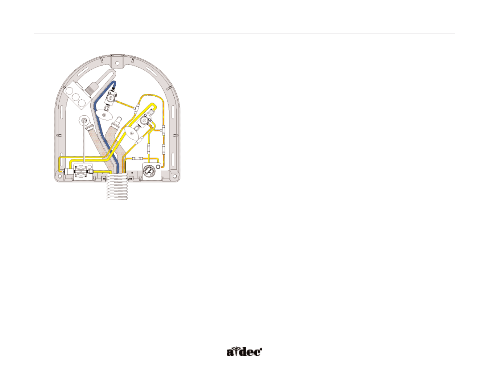
How the Floor Box Functions
Air and Water Manual Shutoff Valves
Shutoff valves supply the air and water to the unit. To prevent leaks, these
valves should remain fully open (turned counterclockwise) except while the
unit is being serviced.
Gauge and Pre-Regulator
The pre-regulator controls the air and water pressure in the unit. The gauge
displays the unit air pressure.
A
B
F
C
D
E
G
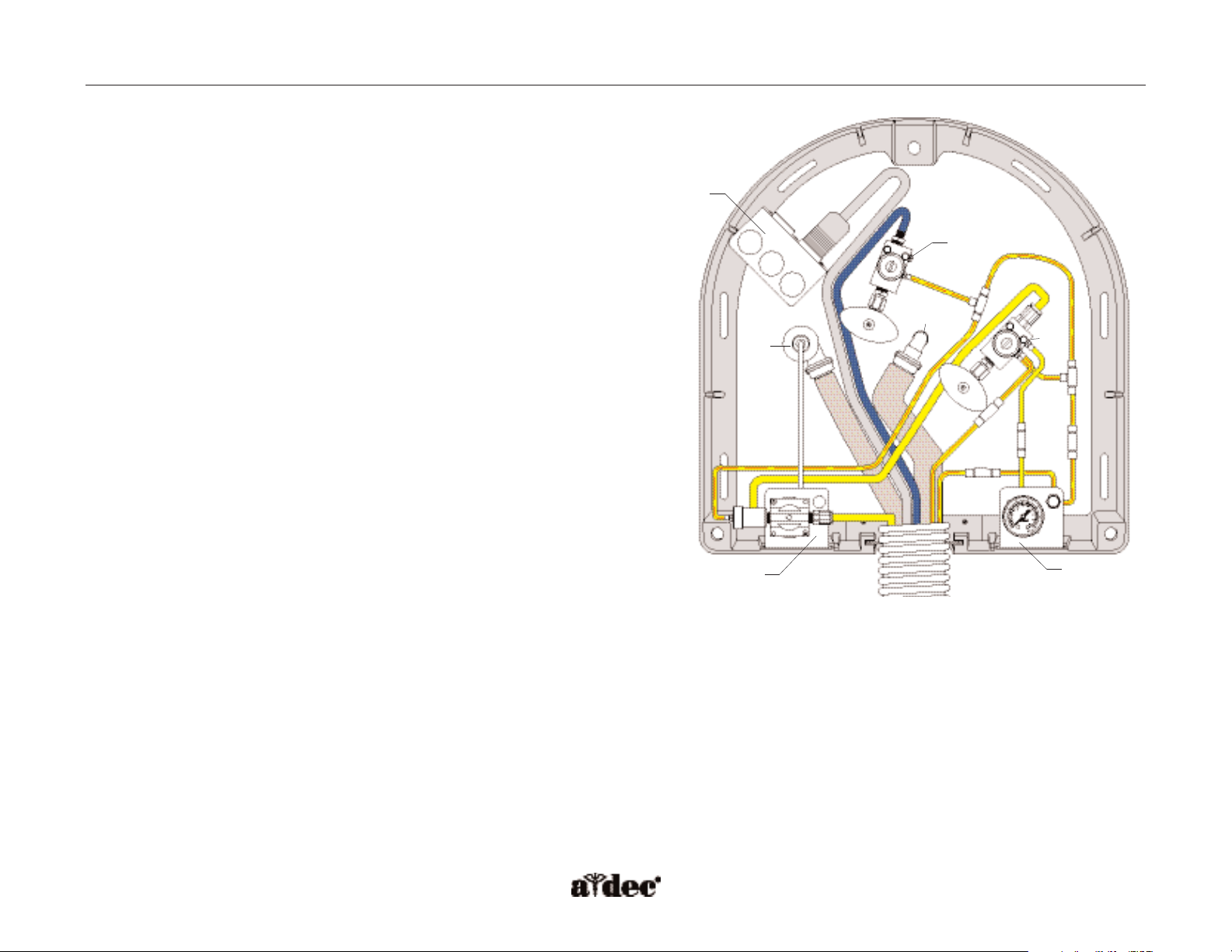
Figure 96. Identification of the floor box utilities. (A) electrical
duplex outlet; (B) water filter regulator; (C) Air filter regulator;
(D) gauge and pre-regulator assembly; (E) moisture separator;
(F) vacuum drain; (G) cuspidor drain
Page 3
85.0816.00 Rev A 2004-11 (PCA 04002.12) Page 137
A-dec Service Guide, Vol. II Floor Box
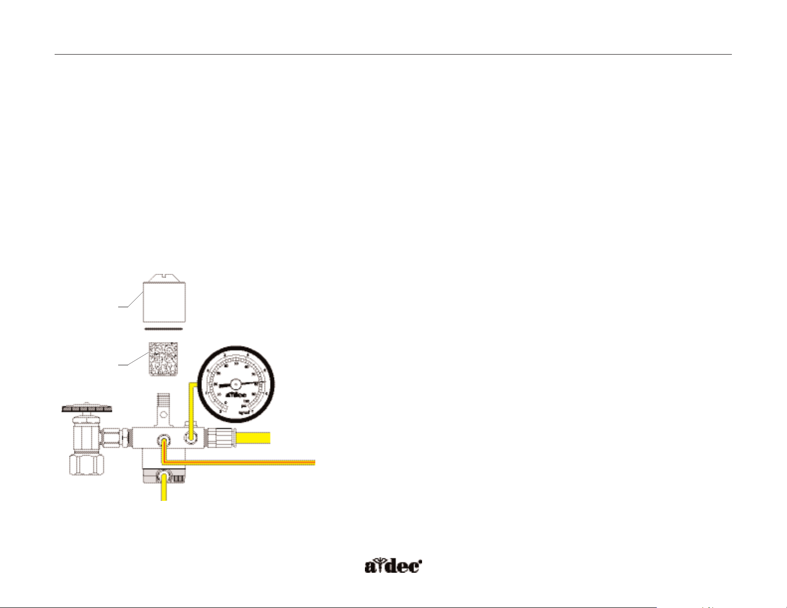
Filter Element
A clogged filter will reduce the amount of air and water pressure available to the unit.
1. Move the master On/Off toggle to OFF.
2. Close the manual shutoff valves.
3. Bleed the system of air and water pressure by operating the syringe buttons until air and water no longer flow.
4. Remove the filter housing from the air and/or water regulator assembly with a flat blade screwdriver.
5. Replace the filter if it is visibly clogged or discolored.
6. Install the new filter with the beveled edge toward the manifold.
NOTE: The system will not work properly if the filter is installed incorrectly.
Figure 97. Replace the filter by removing the filter housing
and installing the new filter beveled edge down. (A) filter
housing; (B) new filter
A
B
Page 4

Page 138 85.0816.00 Rev A 2004-11 (PCA 04002.12)
Item #
Part Number
Description
1
004.005.02
Washer, flat, nylon .187 ID, pkg 10
2
023.004.03
Barb, 1/8" x 10-32", pkg 10
3
001.026.00
Screw, 6-32" x 7/8", socket head
4
24.0137.01
Gasket, 9-hole, pkg 10
5
24.0162.00
Manifold, filter/regulator
6
021.042.00
Adapter, 1/8" MPT to 3/8"
7
24.0232.00
Stud, filter regulator/manifold assembly
8
24.0234.01
Filter element, filter/regulator, pkg 6
9
030.019.03
O-ring
10
24.0229.00 Housing, filter
11
021.016.04 Plug, hex 10-32", pkg 10
12
022.088.00 Fitting, push in, 5/16" x 1/8"
13
023.804.00 Barb, 5/16" x 1/8"
1
2
3
4
5
6
7
8
9
10
11
12
13
Illustrated Parts A-dec Service Guide, Vol. II
Air and Water Filter Regulators
The air and water filter regulators combine air-actuated shut-off valves with filter assemblies.
The filter regulators automatically shut off air and water to the system when the master On/Off
toggle is in the Off position. This safety feature prevents water damage in the event of a water
leak while the unit is unattended. The filters prevent solids from entering the unit.
Figure 98. Identification of the air and water filter
regulator components.
Page 5

85.0816.00 Rev A 2004-11 (PCA 04002.12) Page 139
A-dec Service Guide, Vol. II Illustrated Parts
Item #
Part Number
Description
1
001.024.00
Screw, socket head, 4-40" x 3/8" SST
2
001.021.00
Screw, socket head, 4-40" x 1/2" SST
3
24.0368.00
Valve cover
4
004.005.02
Washer, flat, nylon .187 ID, pkg 10
5
023.004.03
Barb, 1/8" x 10-32, pkg 10
6
22.0440.02
Diaphragm, pkg 10
7
24.0142.00
Plunger
8
24.0140.00
Spacer, water regulator
9
24.0132.00
Piston with O-ring, Delrin
10
013.032.00 Spring, compression .250/.350 OD (water)
11
22.0460.00 Spring, conical (air)
12
24.0135.00
24.0355.00
Body, regulator, white (air)
Body, regulator, black (water)
1
2
3
4
5
6
7
8
9
11
12
Air Water
Figure 99. Identification of the air and water filter regulator
body assembly components.
Air and Water Filter Regulators Body Assembly
10
Page 6

Page 140 85.0816.00 Rev A 2004-11 (PCA 04002.12)
Illustrated Parts A-dec Service Guide, Vol. II
A-dec Moisture Separator
The moisture separator is used to separate moisture from the compressed air.
Item #
Part Number
Description
1
026.173.00
Moisture separator, auto
2
41.1469.01
Diaphragm, .75" OD x .013", pkg 5
3
004.005.02
Washer, flat nylon, .187 ID, pkg 10
4
023.004.03
Barb, 1/8" x 10-32, pkg 10
5
023.804.00*
Barb, 5/16" x 1/8"
6
023.066.00
Barb, 1/8" x .206-36
7
022.088.00*
Fitting, push in, 5/16" x 1/8"
8
24.0472.00
Bracket, gauge/moisture separator
9
001.033.00
Screw, socket head, 6-32" x 3/8"
1
2
3
4
5
6
7
8
9
Figure 100. Identification of the moisture separator components.
* Item not for sale.
Page 7

85.0816.00 Rev A 2004-11 (PCA 04002.12) Page 141
A-dec Service Guide, Vol. II Master On/Off Toggle
Floor Box Master On/Off Toggle
(P/N 90.1088.00)
The floor box can have a master On/Off toggle kit installed for units that
have a support side system, but no delivery system.
To install the master On/Off toggle valve assembly:
1. Drill a 15/32" diameter hole in the floor box base.
2. Install the master toggle valve assembly (Refer to the Master On/Off
Toggle Flow Diagram).
3. Disconnect the master air line from the in-line fitting on the air
filter/regulator assembly (this will not be used).
4. Connect the master toggle to the master air line.
5. Connect the pilot air tubing to the pilot air fitting on the chair
air/water manifold.
NOTE: Plug the master port to the delivery system on the chair
air/water manifold.
Hole location
A
B
A
C
Figure 101. Floor box master On/Off toggle.
(A) nut; (B) washer; (C) toggle valve
Page 8

Page 142 85.0816.00 Rev A 2004-11 (PCA 04002.12)
Chair air/water manifold
Master On/Off toggle
Air filter/regulator
To assistant’s arm
Air source
Flow Diagram A-dec Service Guide, Vol. II
Master On/Off Toggle Flow Diagram
Page 9

85.0816.00 Rev A 2004-11 (PCA 04002.12) Page 143
How to Troubleshoot the Floor Box
Tips and troubleshooting information are listed in the table to assist in diagnosing floor box problems.
This table is not intended to cover every situation, but does include the most common problems that may
be encountered.
A-dec Service Guide, Vol. II Floor Box Troubleshooting
Problem Possible Cause Action
Unit air pressure drops when unit is in use Plugged filter element in air filter/regulator • Flip the master On/Off toggle to the On position and remove the floor
box cover.
• Locate and observe the air pressure gauge in the floor box while
pressing the syringe air button.
If the air pressure drops more than 15 psi, the air filter is clogged. Replace filter.
Low unit water pressure, unit air will not
shut off
Plugged filter element in the water filter/
regulator assembly, or a plugged water filter
screen in the manual shutoff valve
• Flip the master On/Off toggle to the On position and then remove the
floor box cover.
• Locate and observe the water pressure gauge in the floor box and press
the syringe water button.
If the water pressure gauge drops more than 10 psi, the water filter element
and/or the water filter screens are clogged and must be replaced.
Inspect the water filter screen.
•With the master On/Off toggle in the Off position, close the manual
shutoff valves. Bleed the system of air and water pressure.
• Loosen the compression nut to remove the water filter regulator
assembly. Remove and discard the filter screen.
• Install a new filter screen and reinstall the water filter regulator
assembly.Tighten the compression nut.
• Open the water manual shutoff valve and flip the master On/Off
toggle to the On position. Check the fitting for leaks.
Page 10

Page 144 85.0816.00 Rev A 2004-11 (PCA 04002.12)
 Loading...