

Page 1
85.0816.00 Rev A 2004-11 (PCA 04002.12) Page 1
A-dec Service Guide, Vol. II Programming
A-dec 500 offers a variety of programming options. The DCS technology used in the A-dec 500
product allows programmability of the touchpad(s) and footswitch. Some of the features that can
be programmed are:
• Handpieces — operation, speed and air/water coolant
• Chair operation and back/base positions
• Dental light On/Off, and composite intensity setting
• Cuspidor operation and cup fill/bowl rinse timing
• Dual operator settings
This section provides programming information for all of the A-dec 500 modules as well as
information related to servicing, maintenance, and adjustments. Detail on how to service the
touchpads and troubleshoot specific problems is presented. For information on service parts,
see the Genuine A-dec Service Parts Catalog or contact A-dec customer service.
Page 2
Page 2 85.0816.00 Rev A 2004-11 (PCA 04002.12)
Chair Programming A-dec Service Guide, Vol. II
How to Program the Chair
Position Programming
1. Position the chair to the desired operating position, using the manual controls (arrows)
on the touchpad or footswitch.
2. Press and release Program button (one beep).
3. Press a position button (three beeps).
Position 3 (X-ray/Rinse)
Position 3 can be programmed as either an x-ray/rinse position or a programmed position.
To program Position 3, press and hold Program and Position 3 together for three seconds.
One beep confirms that the position can be programmed. To return to the x-ray/rinse
position, repeat.
Three beeps confirms that the x-ray/rinse function is on.
NOTE: Disabling the x-ray/rinse function is a global function for the dual operator
mode (A/B) on a deluxe touchpad.
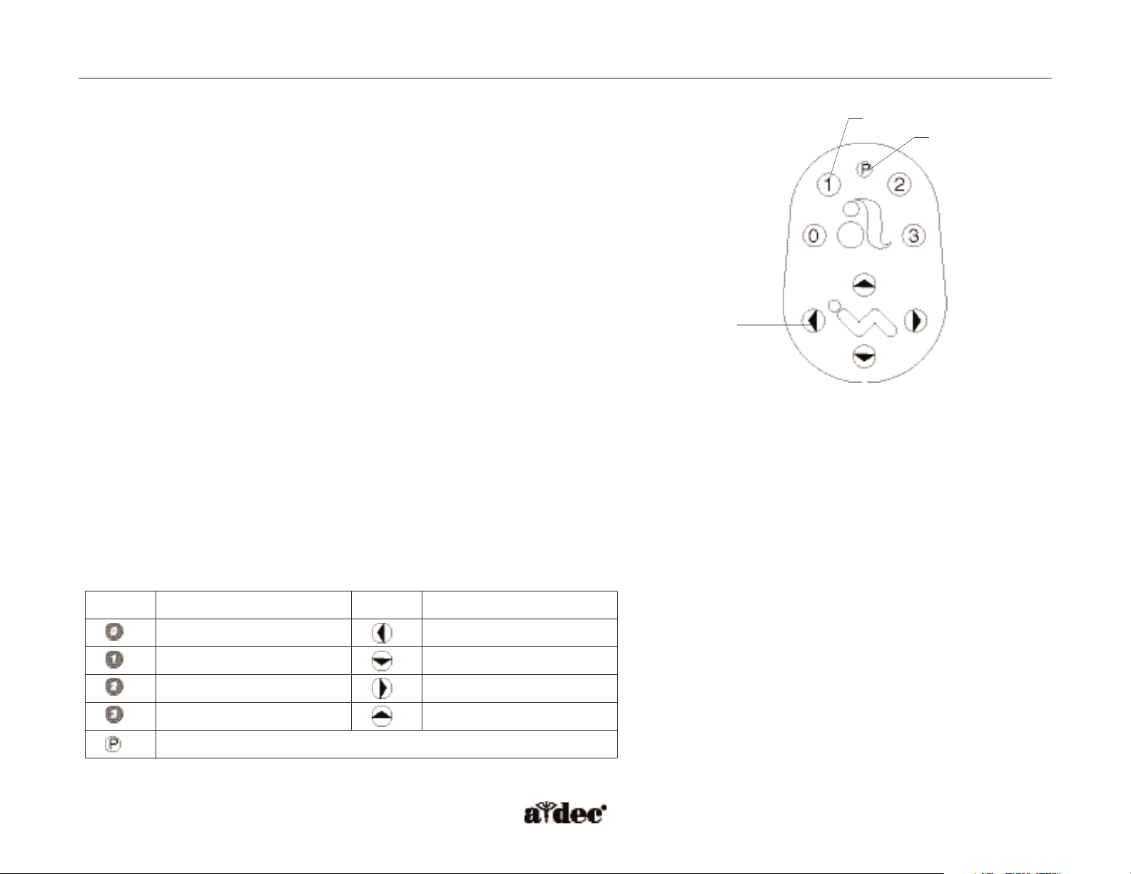
Figure 8. Footswitch buttons. (A) position button;
(B) program button; (C) manual control
B
A
C
Icon Description
Icon Description
Entry/exit
Back down
Position 1
Base down
Position 2
Back up
Position 3 (x-ray/rinse)
Base up
Program button
Footswitch Icons
Page 3
85.0816.00 Rev A 2004-11 (PCA 04002.12) Page 3
A-dec Service Guide, Vol. II Delivery System Programming
How to Program the Delivery System
When programming the delivery system, one beep indicates program mode and three
beeps confirms programming. When overriding features (Auto On/Off dental light function
and Position 3 [x-ray/rinse], and combined air/water coolant), one beep means the factory
preset is disabled and three beeps means the factory preset is active.
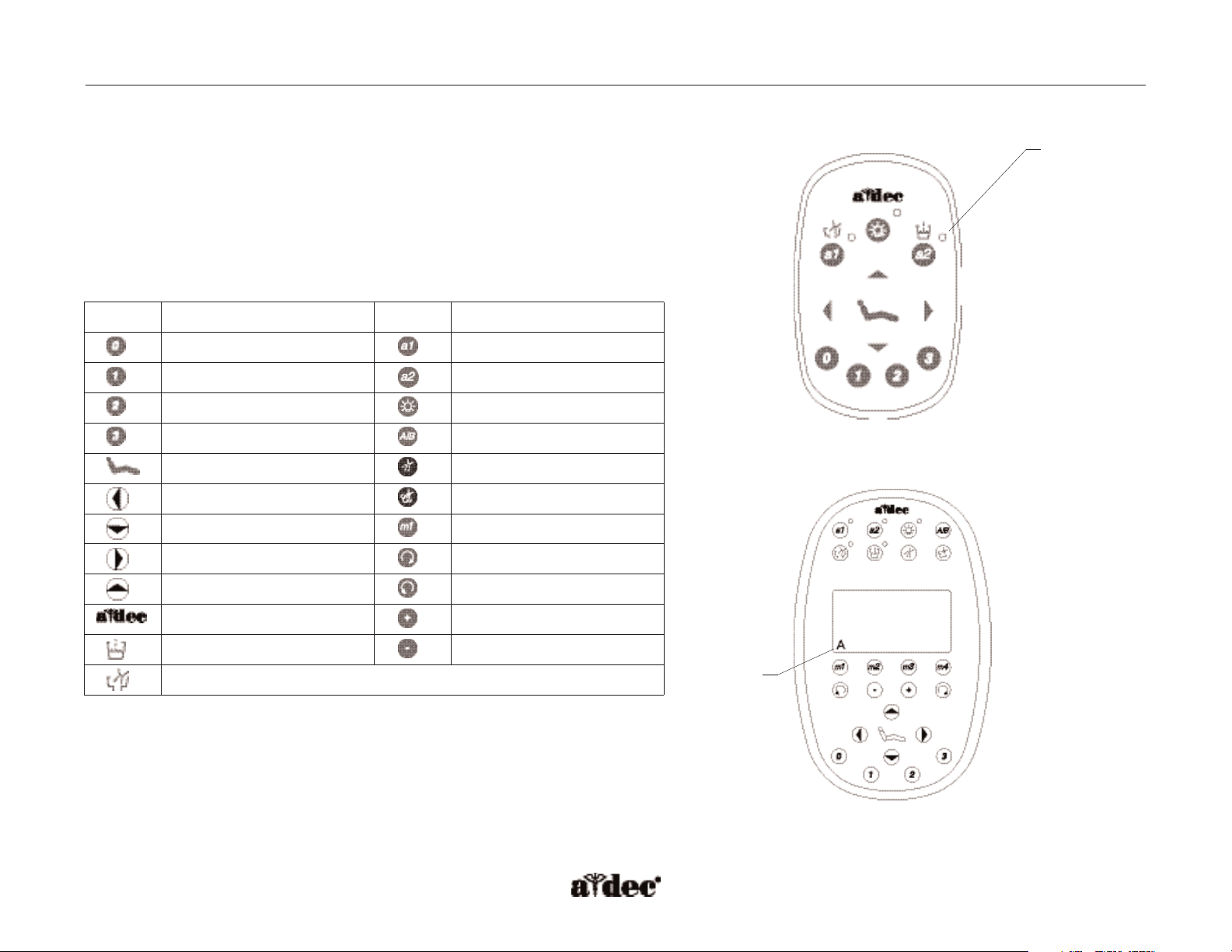
Touchpad Icons
Icon Description
Icon Description
Entry/exit
a1 auxiliary 1
Position 1
a2 auxiliary 2
Position 2
Light
Position 3 (x-ray/rinse)
Dual operator mode (A/B)
Program button
Water coolant
Back down
Air coolant
Base down
Memory positions (M1-M4)
Back up
Forward
Base up
Reverse
Status icon
Increase
Cup fill
Decrease
Bowl rinse
Figure 9. Standard touchpad. (A) indicator light
Figure 10. Deluxe touchpad. (A) operator mode
A
A
Page 4
Page 4 85.0816.00 Rev A 2004-11 (PCA 04002.12)
Delivery System Programming A-dec Service Guide, Vol. II
Dual Operator Mode (A/B)
The dual operator mode on the deluxe touchpad provides additional programmable positions for a second operator.To program the delivery
system for two operators, first select the operator mode being programmed (A/B).A letter in the lower left corner of the touchpad screen will
appear showing the active mode. Program the appropriate function.
Handpiece Configuration for Deluxe Touchpad
To field install a handpiece or upgrade to a deluxe touchpad, configure each handpiece position.
•Press and hold Program and A/B together until the touchpad switches to ”select handpiece.”
• Activate the handpiece being configured, and follow the steps displayed on the touchpad screen.
Programming Memory
The memory settings (M1-M4) are different for both operator A and B modes and for each handpiece position. All memory settings are factory
preset with both the air and water coolant on.
Electric Micromotor
When activated, the desired maximum RPM can be programmed into one of the four pre-programmed memory settings. To adjust the RPM limit,
use Plus (+) and Minus (-). Select water and air coolant to be on or off, and press Program and the Memory button (m1-m4). Three beeps
confirms the setting. The total range is 300-40,000 RPM. An RPM limit bar shows the RPM level for the electric micromotor.
EXAMPLE: If the RPM limit is set for 40,000 RPM and the power limit bar shows half, then the electric micromotor is operating at
approximately 20,000 RPM.
The maximum RPM limits are preset to the following:
Preset Maximum RPM
m1
2,000
m2
10,000
m3
20,000
m4
40,000
Page 5
85.0816.00 Rev A 2004-11 (PCA 04002.12) Page 5
A-dec Service Guide, Vol. II Delivery System Programming
Scaler
When activated, the desired power level can be programmed into one of the four pre-programmed memory settings. To adjust the power level
(0 to 100%), use Plus (+) and Minus (-). Select water coolant to be On or Off, and press Program and the Memory button (m1-m4). Three
beeps confirms the setting. A power limit bar shows the power level to the scaler.
EXAMPLE: If the power limit is set for 50 percent and the bar shows half, then the scaler is operating at approximately 25 percent power.
The maximum power level limits are preset to the following:
Preset Power Level Limit
m1
25%
m2
50%
m3
75%
m4
100%
NOTE: When the deluxe touchpad displays zero percent, the scaler continues to operate at minimum power causing tip movement.
WARNING: Do not attempt to change the scaler tips when the unit is operating.
Page 6

Page 6 85.0816.00 Rev A 2004-11 (PCA 04002.12)
Cuspidor and Light Programming A-dec Service Guide, Vol. II
How to Program the Cuspidor
Cup Fill and Bowl Rinse Functions
Cup fill and bowl rinse functions can be programmed using a touchpad or the combination of a footswitch program button and the appropriate
button on the cuspidor tower.
1. Press Program (one beep).
2. Press and hold Cup Fill or Bowl Rinse for desired time.
3. Release button (three beeps).
How to Program the Dental Light
Dental Light (Auto On/Off)
The Auto On/Off setting can be turned off by pressing and holding Program and Light together for three seconds. One beep confirms the
function has been turned off. To enable the function, repeat.
Three beeps confirms the Auto On/Off function is on.
Page 7

85.0816.00 Rev A 2004-11 (PCA 04002.12) Page 7
LED Assistant's Touchpad and Standard Touchpad Deluxe Touchpad
Status (A-dec logo) Off = System is not functioning
Blue steady = Normal condition (ready for use)
Blue double blink = Jumper is in factory default position on the chair circuit board
Blue slow blink = Chair, cuspidor, or lower support arm stop switch is activated
Dental light Off = Dental light is off
YYellow steady
ellow steady = Dental light is on in high or medium intensity
YYellow slow blink
ellow slow blink = Dental light is on in composite intensity
Auxiliary #1 or
bowl rinse
Off = Auxiliary #1 is off or bowl rinse is off N/A (see bowl rinse)
YYellow
ellow = Auxiliary #1 is on or bowl rinse is on N/A (see bowl rinse)
Auxiliary #2 or
cup fill
Off = Auxiliary #2 is off or cup fill is off N/A (see cup fill)
YYellow
ellow = Auxiliary #2 is on or cup fill is on N/A (see cup fill)
Bowl rinse N/A (shared with auxiliary #1 above) Off = bowl rinse is off
YYellow
ellow = bowl rinse is on
Cup fill N/A (shared with auxiliary #2 above) Off = cup fill is off
YYellow
ellow = cup fill is on
Auxiliary#1 or #2 N/A (shared with auxiliary #1 or #2 above) Off = Auxiliary device is off
YYellow
ellow = Auxiliary device is on
LED Troubleshooting
These tables are intended for use when diagnosing equipment problems using the circuit board LEDs.The
most common problems that may be encountered are shown.The first table lists problems commonly
diagnosed by phone with the dental staff. Additional tables show more complex troubleshooting.
Off = Function is turned off, device is disconnected, no power, or failed circuit board
Blue steady = Normal operation
YYellow
ellow = Advisory
A-dec Service Guide, Vol. II LED Troubleshooting Quick Start
Page 8

Page 8 85.0816.00 Rev A 2004-11 (PCA 04002.12)
LED A-dec Relay Module Dental Light Cuspidor Delivery System Chair
AC power Off = No 24 VAC power, open circuit breaker, power supply turned off, no line voltage
Green steady = 24 VAC power at terminal strip
Status Off = System is not functioning, no power or circuit board has failed Off = System is not functioning,
no power or circuit board
has failed
Green steady = normal condition Green steady = normal condition
Green double blink = jumper is
in the factory default position
Data (DCS) Off = No data communication, not connected to the data line connector, data line is not functioning
Green steady = Active DCS is detected
Green double blink = Valid DCS message
A-dec relay Off = Relay is off N/A Off = Relay is off N/A N/A
YYellow
ellow = Relay is on
YYellow
ellow = Relay is on
Bowl rinse/cup
fill relays
N/A N/A Off = Relay is off N/A N/A
YYellow
ellow = Relay is on
Cuspidor stop switch N/A N/A Off = Closed (normal) N/A N/A
Red = Open (activated)
IOLS output N/A N/A N/A OFF = IOLS voltage
is OFF
N/A
YYellow
ellow = IOLS
voltage is on
Scaler relay N/A N/A N/A Off = Scaler relay
voltage is off
N/A
YYellow
ellow = Scaler relay
voltage is on
LED Troubleshooting Quick Start A-dec Service Guide, Vol. II
Page 9

85.0816.00 Rev A 2004-11 (PCA 04002.12) Page 9
A-dec Service Guide, Vol. II LED Troubleshooting Quick Start
LED A-dec Relay Module Dental Light Cuspidor Delivery System Chair
Air/water
coolant
solenoids
N/A N/A N/A Off = Solenoid
is off
N/A
YYellow
ellow = Solenoid
is on
Chair or lower
support arm stop
switch
N/A N/A N/A N/A Off = Closed (normal)
Red = Open (activated)
Chair lockout N/A N/A N/A N/A Off = Open (normal)
Red = Closed (activated)
Vacuum Relay N/A N/A N/A N/A Off = Vacuum relay is off
N/A N/A N/A N/A
YYellow
ellow = Vacuum relay is on
Dental light N/A N/A N/A
Chair position
sensors
N/A N/A N/A N/A Off = Sensor not connected, bad
connection, moving in wrong
direction, limited range of motion,
or cable not on wheel
N/A N/A N/A N/A
YYellow steady
ellow steady =
Normal operation
N/A N/A N/A N/A
YYellow fast blink
ellow fast blink = Upper end
of travel
Back and
base relays
N/A N/A N/A N/A Off = Relay is off
N/A N/A N/A N/A
YYellow
ellow = Relay is on
DS4 DS5 Function
Off Off Off
On Off High intensity
Off On Composite intensity
On On Medium intensity
DS8 DS7 Function
Off Off Off
On Off High intensity
Off On Composite intensity
On On Medium intensity
Page 10

Page 10 85.0816.00 Rev A 2004-11 (PCA 04002.12)
Page 11

85.0816.00 Rev A 2004-11 (PCA 04002.12) Page 11
A-dec Service Guide, Vol. II Touchpad Programming
How to Program Touchpads
The touchpads are the primary user interface for the A-dec 500 system. The buttons on the touchpad position the chair, initiate the cup fill and
bowl rinse, and turn the dental light on and off. The deluxe touchpad has an LCD display and additional buttons for memory control.
Factory Preset Functions
The disable/enable function located on the chair circuit board, applies to any touchpads or footswitch attached to the A-dec 500 system.
However, the disable/enable function does not carry over with touchpads if they are removed from one system and installed on another system.
Disable/Enable the Footswitch or Touchpad
Disable
1. Place the “spare”jumper in the “EN/DIS TP/FS”position of the test points header P3.
2. Push the buttons to be disabled (PRGM, PRGM 0, PRGM 1, PRGM 2, PRGM 3).
One beep means the button is disabled.
3. Place the “spare”jumper back into the “spare”position of the test points header P3.
Enable
1. Place the “spare”jumper in the “EN/DIS TP/FS”position of the test points header P3.
2. Push the buttons to be enabled (PRGM, PRGM 0, PRGM 1, PRGM 2, PRGM 3).
Three beeps means the button is enabled.
3. Place the “spare”jumper back into the “spare”position of the test points header P3.
Page 12

Page 12 85.0816.00 Rev A 2004-11 (PCA 04002.12)
How to Identify the Touchpad Circuit Board Components
Standard Touchpad
The standard touchpad has two LEDs for communicating status (AC Power and Data). The touchpad circuit board’s Status LED is the A-dec icon,
visible on the touchpad. Check the chair circuit board LEDs, as well as the touchpad, when troubleshooting.
Figure 11. Standard touchpad circuit board components.
Item # Description
1
DS1 - AC power LED
2
DS2 - Status LEDs
3
DS3 - Data LED
4
J1 - Ø VAC terminal strip
5
J1 - 24 VAC terminal strip
6
P1 - Data line port (DCS)
7
J2 - Electric holder terminal strip
8
DS7 - Auxiliary 1 and bowl rinse LED
9
DS8 - Dental light LED
10
DS9 - Auxiliary 2 and cup fill LED
Standard Touchpad Circuit Board A-dec Service Guide, Vol. II
7
6
4
5
1
3
2
9
10
8
Page 13

85.0816.00 Rev A 2004-11 (PCA 04002.12) Page 13
A-dec Service Guide, Vol. II Deluxe Touchpad Circuit Board
Deluxe Touchpad
Figure 12. Deluxe touchpad circuit board components.
Item # Description
1
DS1 - AC power LED
2
DS2 - Status LEDs
3
DS3 - Data LED
4
J1 - Ø VAC terminal strip
5
J1 - 24 VAC terminal strip
6
P1 - Data line port (DCS)
7
P2 - LCD display connector
8
P3 - LCD back light power connector
9
DS6, DS17 - Auxiliary 1 LED
10
DS7, DS18 - Auxiliary 2 LED
11
DS8, DS19 - Bowl rinse LEDs
12
DS9, DS11 - Cup fill LEDs
13
DS10 + 20 - Dental light LEDs
14
LCD display
1
2
13
10
3
4
5
8
6
7
9
11
12
14
Page 14

Page 14 85.0816.00 Rev A 2004-11 (PCA 04002.12)
Touchpad Troubleshooting A-dec Service Guide, Vol. II
Cup fill
Off
N/A - shared with auxiliary #2
Cup fill is off
Yellow Cup fill is on
Auxiliary #1 or #2 Off N/A - shared with cup fill and bowl rinse Auxiliary device is off
Yellow Auxiliary device is on
How to Troubleshoot the Touchpads
Tips and troubleshooting information are listed in the tables to assist in diagnosing touchpad problems.
These table details how to troubleshoot the touchpad using LEDs. They are not intended to cover every
situation, but do include the most common problems that may be encountered.
LED Status Standard Touchpad Deluxe Touchpad
Status (A-dec logo)
Off System is not functioning, device is disconnected, no power, or failed touchpad circuit board
Blue, steady Normal condition
Blue, double blink Spare jumper is in factory default position on the chair circuit board
Blue, slow blink Chair or cuspidor stop switch is activated
Dental light
Off Dental light is off
Yellow, steady Dental light is on in high or medium intensity
Yellow, slow blink Dental light is on in composite setting
Auxiliary #1 or
bowl rinse
Off Auxiliary #1 or bowl rinse is off
N/A - uses individual LEDs
Yellow Auxiliary #1 or bowl rinse is on
Auxiliary #2 or
cup fill
Off Auxiliary #2 or cup fill is off
N/A - uses individual LEDs
Yellow Auxiliary #2 or cup fill is on
Bowl rinse
Off
N/A - shared with auxiliary #1
Bowl rinse is off
Yellow Bowl rinse is on
Page 15

85.0816.00 Rev A 2004-11 (PCA 04002.12) Page 15
A-dec Service Guide, Vol. II Touchpad Troubleshooting
LED Status Description
DS1 — AC power Off No 24 VAC power. Check for tripped circuit breaker, power supply turned off, or
no line voltage.
Green, steady Normal operating mode.
DS3 — Data Off No data communication. Data line is not connected. Data line not functioning.
Green, steady Detects active DCS.
Green, blinking Valid DCS message.
Touchpad Problem Possible Cause Action
Standard and deluxe Dental light does not turn off from the
touchpad button
Operator error Press and hold dental light button for two seconds.
Some or all buttons do not function
when pressed
Circuit board is not fully snapped into the
touchpad housing, or the plastic snaps are
broken off
Inspect the circuit board to make sure all six plastic snaps
are secure. If plastic snaps are broken, then replace the
touchpad assembly.
Deluxe LED display is not backlit Bad connection or broken wire Check wires and connection at connector P3 (back side of
the circuit board).
LED display is backlit, but does not
display any text or icons
Bad circuit board
Bad connection or misaligned ribbon cable
in connector P2
1. Check status LED (DS2) on the front side of the
touchpad. If the LED is off and AC power is on; turn
power OFF and then back ON. If status LED is still off,
replace the touchpad assembly.
2. If status LED is on, turn power to the touchpad OFF
and remove the ribbon cable from the connector (lift
up). Reinsert the ribbon cable, making sure it is located
correctly, and turn the power ON.
Page 16

Page 16 85.0816.00 Rev A 2004-11 (PCA 04002.12)
 Loading...