

Page 1
85.0816.00 Rev A 2004-11 (PCA 04002.12) Page 97
A-dec Service Guide, Vol. II Assistant’s Instrumentation
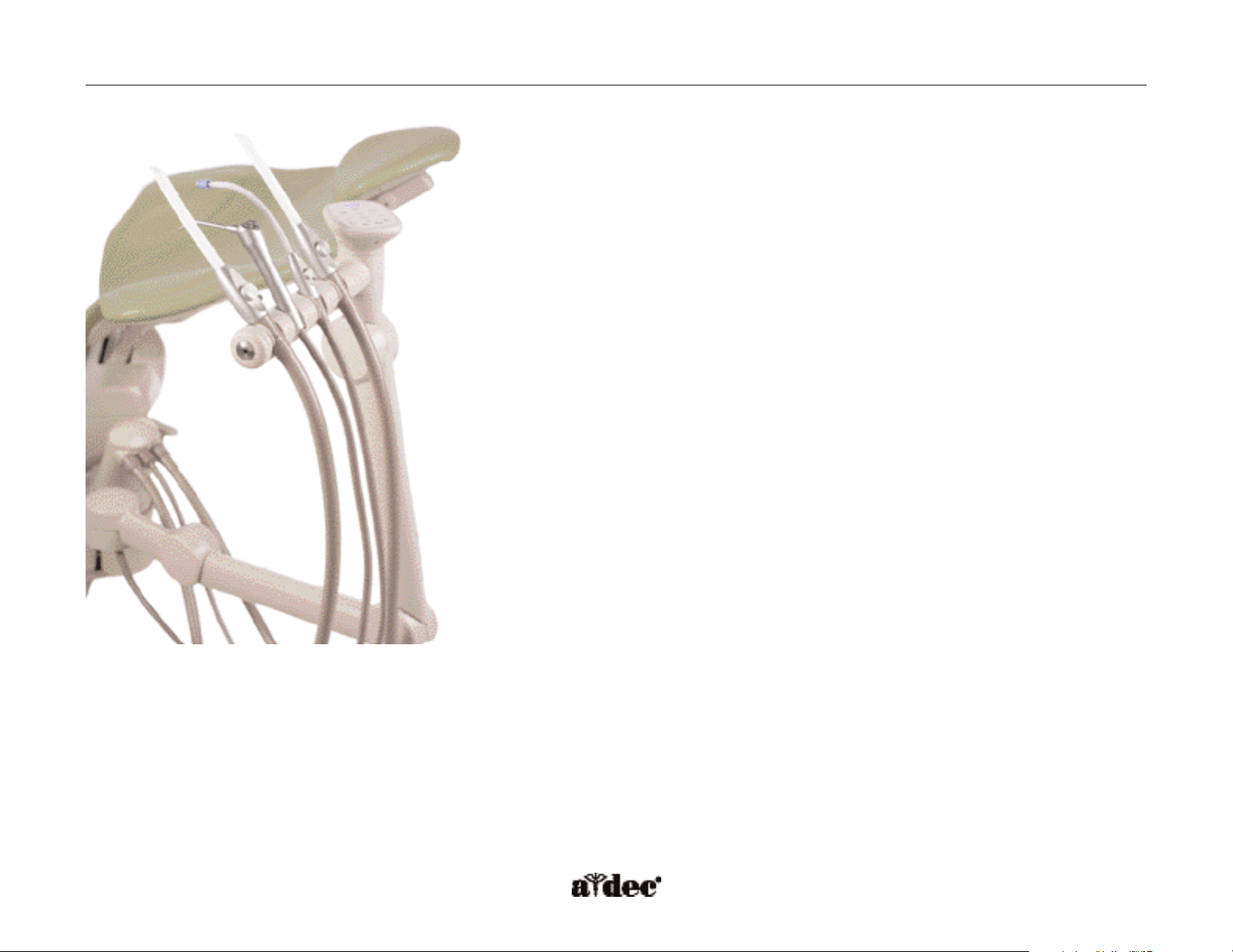
The A-dec 551 assistant’s instrumentation is equipped with either a short or long
assistant’s arm for easy positioning of instrumentation. Both arms are equipped with a
touchpad and a holder assembly with independent positioning features. The solids
collector is also a part of the assistant’s instrumentation, located at the base of the arm.
This section provides information related to servicing, maintenance, and adjustments.
Detail on how to service the assistant’s instrumentation and troubleshoot specific
problems is presented. For information on service parts, see the Genuine A-dec Service
Parts Catalog or contact A-dec customer service.
Page 2
Page 98 85.0816.00 Rev A 2004-11 (PCA 04002.12)
Assistant’s Instrumentation Feature A-dec Service Guide, Vol. II
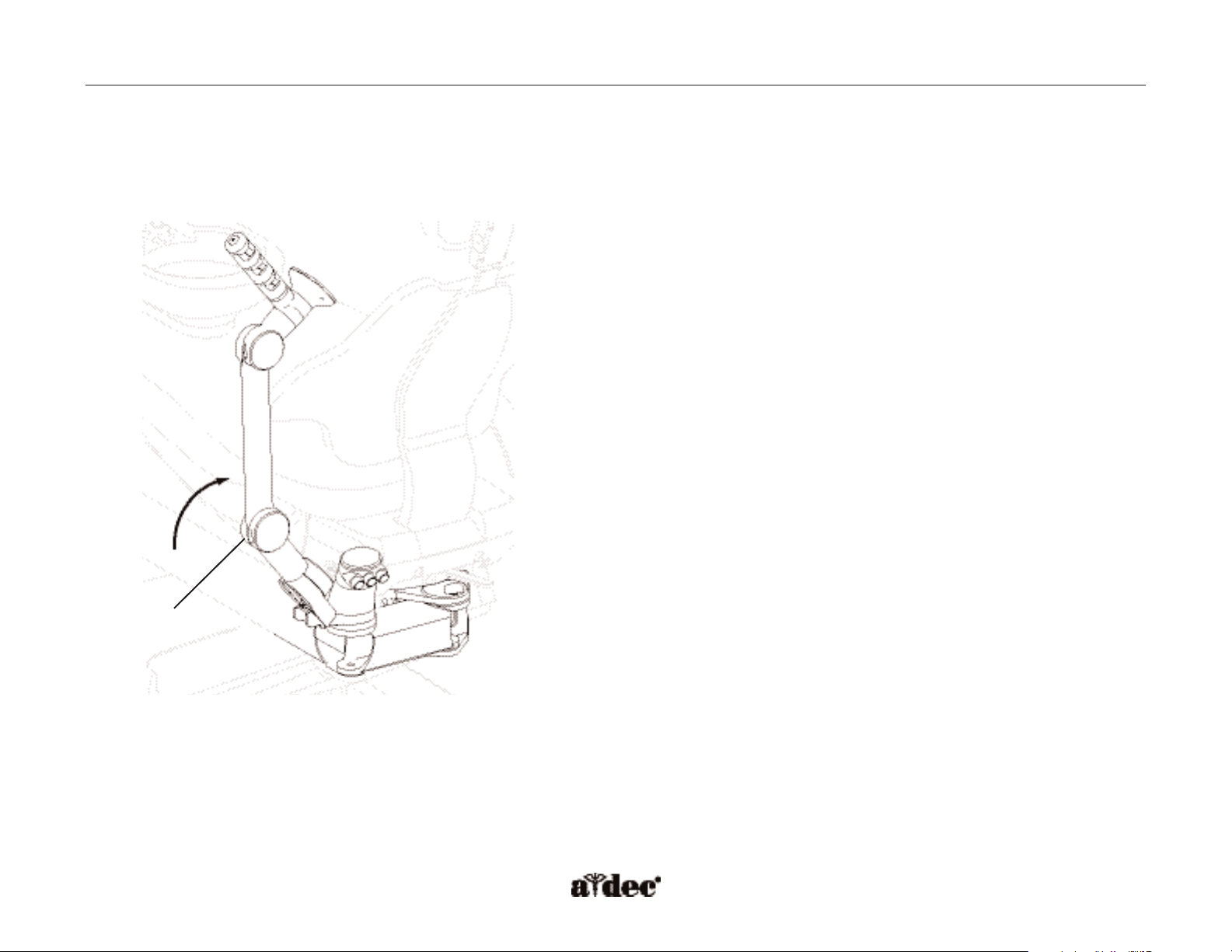
Tip-Up Feature
A pivot joint, located close to the support link, allows the entire arm to tip-up, when it contacts an object.
Figure 67. Assistant’s arm demonstrating the tip-up feature.
Pivot joint
Page 3
85.0816.00 Rev A 2004-11 (PCA 04002.12) Page 99
A-dec Service Guide, Vol. II Assistant’s Instrumentation Components
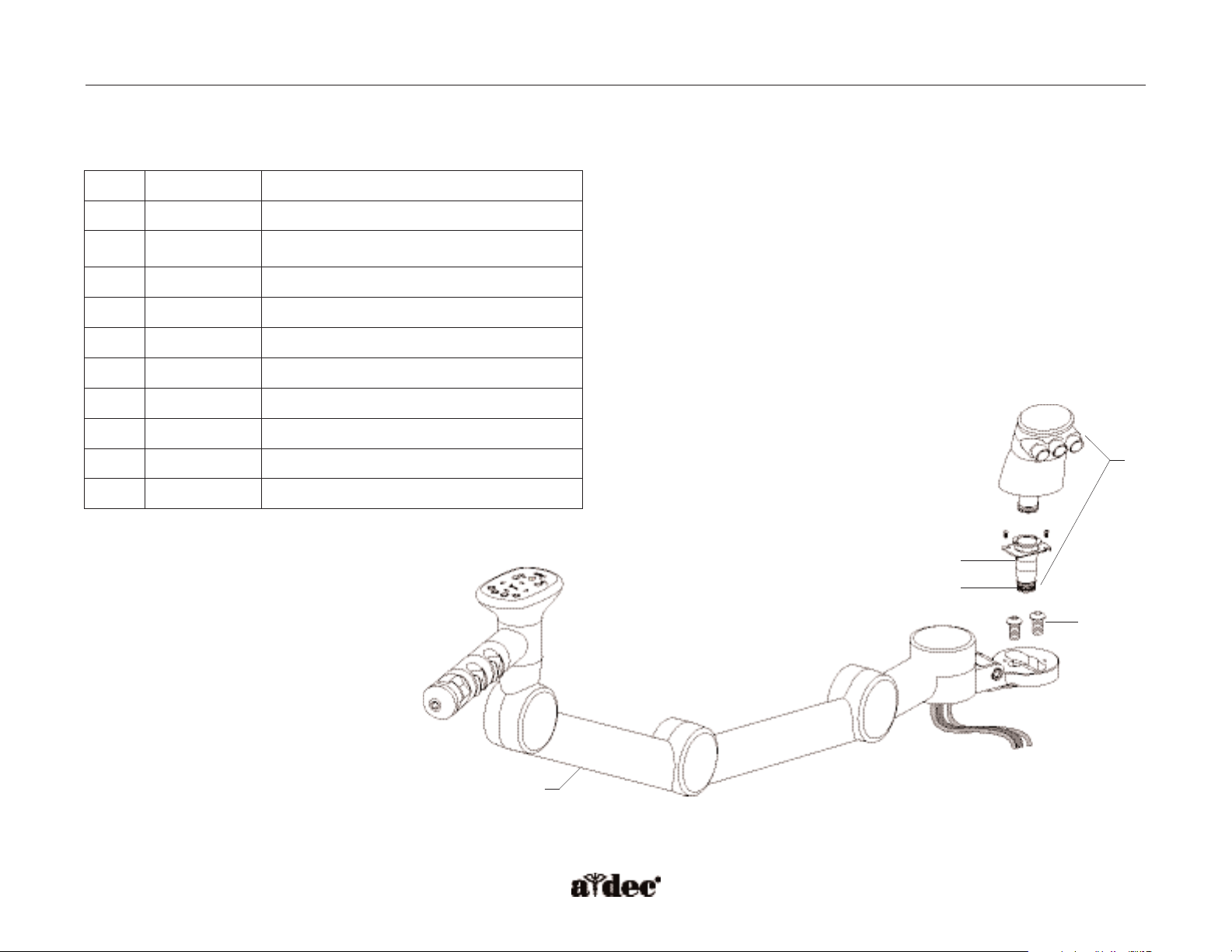
How to Identify A-dec 551 Assistant’s Instrumentation Components
Figure 68. Assistant’s long arm assembly with a single 3 position holder assembly.
Item #
Part Number
Description
1
77.0315.00
Long arm with single 3 position standard holder
—
77.0316.00
Long arm with single 4 position standard holder
—
77.0317.00
Long arm with dual 2 position standard holder
—
77.0322.00 Short arm with single 3 position standard holder
—
77.0323.00 Short arm with single 4 position standard holder
—
77.0324.00 Short arm with dual 2 position standard holder
2
77.0121.00 Vacuum pipe
3
035.053.01
O-ring, red, pkg 10
4
002.094.02 Buttonhead socket screw 10-32 x 1/4
5
77.0341.00 Vacuum connector kit
2
3
1
4
5
Page 4
Page 100 85.0816.00 Rev A 2004-11 (PCA 04002.12)
Assistant’s Holders A-dec Service Guide, Vol. II
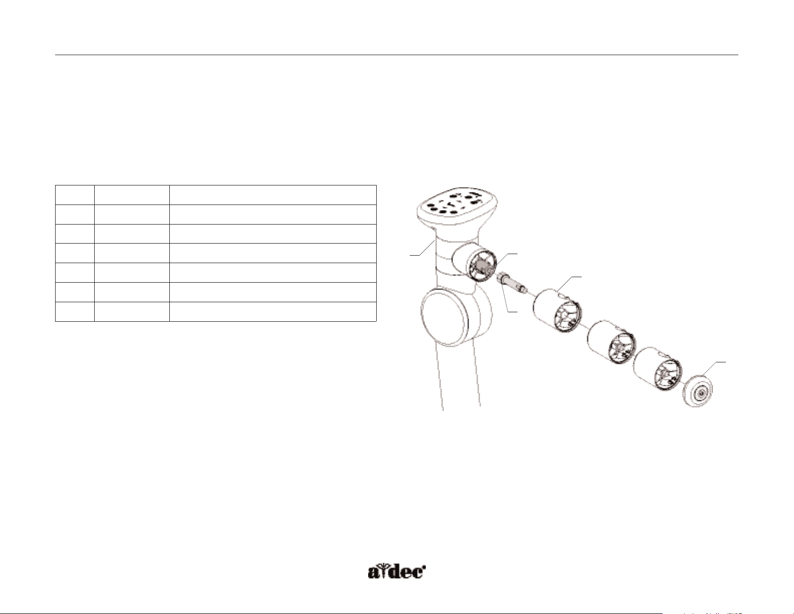
How to Identify Assistant’s Holder
There are two types of assistant’s holders, standard and electric.
Standard Holder
The touchpad does not need to be removed when disassembling the standard holder.
Item #
Part Number
Description
1
99.0649.00
Turret
2
99.0661.00
Turret insert
3
99.0660.00 Axle
4
99.0653.01
Holder, SE, syringe kit
—
99.0650.01
HVE standard kit
5
99.0648.00
End cap assembly
1
2
4
5
3
Figure 69. Identifying assistant’s holder components.
Page 5
85.0816.00 Rev A 2004-11 (PCA 04002.12) Page 101
A-dec Service Guide, Vol. II Flow Diagram
Assistant’s Standard Holder Flow Diagram
This flow diagram describes the plumbing and electrical connections of the assistant’s standard holder assembly and solids collector.
Syringe air/water from
chair air/water manifold
Syringe
SE
HVE
Solids
collector
Touchpad
To v acuum drain (floor box)
300 watt power supply
(chair)
Touchpad
power cable
Data line
Page 6

Page 102 85.0816.00 Rev A 2004-11 (PCA 04002.12)
Assistant’s Holders A-dec Service Guide, Vol. II
Assistant’s Electric Holder
The electric holders provide vacuum On/Off switching for users whose
vacuum system requires this functionality. The vacuum pump will activate
automatically, when the HVE or SE is lifted from the holder.The vacuum will
be turned off, when placed back into the holder.
Power OFF the unit before disassembling the electric holder assembly.The
touchpad needs to be removed when disassembling the electric holders.
Unscrew the end cap assembly to disassemble the individual holder positions.
Item #
Part Number
Description
1
99.0649.00
Turret
2
99.0699.00
Inner hub
3
99.0661.00
Turret insert
4
99.0673.01
Holder, SE electric holder kit
—
99.0674.01
Holder, HVE electric holder kit
5
99.648.00*
End cap assembly
6
99.0698.00 Bearing
7
77.0385.00 Stop
8
99.0687.00 Spacer
9
77.0125.01* Head mount
10
77.0021.00 Knuckle cover
11
99.0660.00 Axle
1
3
2
5
4
6
7
8
9
10
11
Figure 70. Identifying the electric assistant's holder components.
* Item not for sale.
Page 7

85.0816.00 Rev A 2004-11 (PCA 04002.12) Page 103
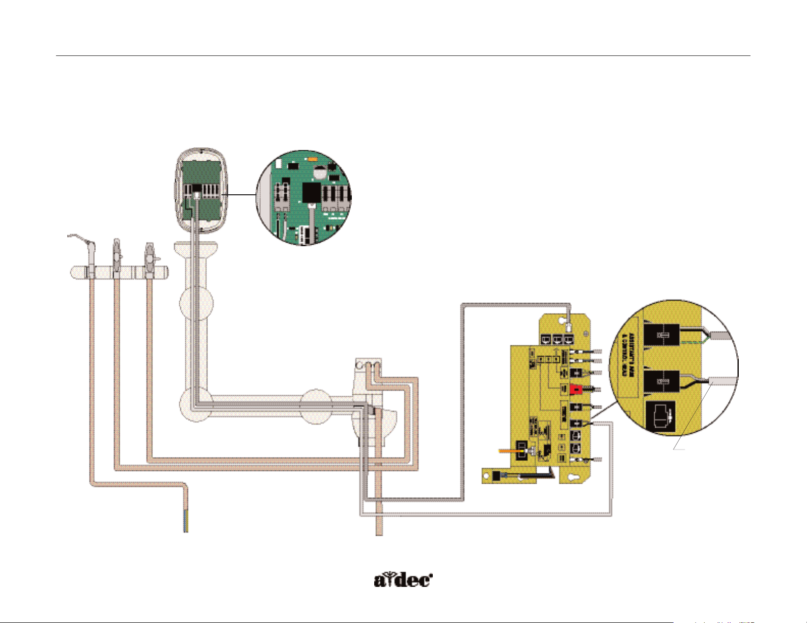
Assistant’s Electric Holder Flow Diagram
This flow diagram describes the plumbing and electrical connections of the assistant’s electric holder assembly and solids collector.
A-dec Service Guide, Vol. II Flow Diagram
To chair air/water manifold
Syringe
SE
HVE
Solids collector
Touchpad
To v acuum drain (floor box)
Touchpad
power wires
Dual electric
holder assemblies
Touchpad
power
wires
Electric
holder
wires
Power supply (chair)
Page 8

Page 104 85.0816.00 Rev A 2004-11 (PCA 04002.12)
Assistant’s Touchpad
The assistant’s instrumentation uses a standard touchpad that serves as a single touch surface for
controlling the chair, dental light, and cuspidor or A-dec relay module (s). The touchpad can rotate 340°
for access and visibility.
Figure 71. Assistant’s touchpad with
standard holder connections. (A) 24 VAC;
(B) data line
Figure 72. Assistant’s touchpad with electric
holder connections. (A) 24 VAC; (B) data line;
(C) electric holder
Item #
Part Number
Description
1
90.1078.00
Standard touchpad with circuit board
2
77.0335.00
Touchpad base
3
025.002.01
Cable tie, pkg 10
4
041.663.00
Cable bushing
5
77.0123.00
Bolt
6
99.0651.00
Spline
7
004.238.00
Washer, Nylatron
8
003.078.00
Socket head screw, 4-40 x 1/4
9
004.237.00
Washer, wave
10
004.060.00* Washer
1
3
4
5
6
7
2
8
7
9
10
Figure 73. Identifying the assistant's
touchpad components.
* Item not for sale.
Illustrated Parts A-dec Service Guide, Vol. II
A
A
B
B
C
Page 9

85.0816.00 Rev A 2004-11 (PCA 04002.12) Page 105
A-dec Service Guide, Vol. II Illustrated Parts
Solids Collector
The solids collector screen prevents solids from entering the central vacuum system when the High Volume Evacuator (HVE) or Saliva Ejector
(SE) are used. A regularly maintained solids collector is necessary for optimal performance of the vacuum system. If the vacuum system
performance is less than optimal, verify that the screen has been replaced.
CAUTION: Use appropriate gloves when handling contaminated parts.
Solids Collector Removal
• Lift off the screen, and cap, then twist off the triple vacuum connector.
•Turn the vacuum tower base to face the back of the chair and lift up.
Item #
Part Number
Description
1
77.0254.00
Vacuum tower cap
2
030.035.02
O-ring, pkg 10
3
11.1284.01
Screen, pkg 10
4
77.0347.00
Connector, triple vacuum
5
77.0362.00
Vacuum tower base with funnel
6
035.053.01
O-ring, red, pkg 10
7
11.1280.00 Cap
1
2
3
2
4
5
6
Figure 74. Identifying the solids collector components.
7
Page 10

Page 106 85.0816.00 Rev A 2004-11 (PCA 04002.12)
Illustrated Parts A-dec Service Guide, Vol. II
Autoclavable HVE Assembly without Tip
(P/N 11.1286.00)
Item #
Part Number
Description
1
11.1071.00
Body
2
11.1074.00
Rotor assembly with O-rings
3
11.0998.01
Screen, pkg 5
4
034.014.01
O-ring
5
11.1292.00
Standard HVE tubing assembly
11.1294.00 11 mm HVE tubing assembly
(adapts 15 mm HVE to standard 11 mm HVE)
6
034.018.00
O-ring
7
034.013.01 O-ring
1
6
3
5
4
6
2
6
7
Figure 75. Identifying the QD
HVE components.
Page 11

85.0816.00 Rev A 2004-11 (PCA 04002.12) Page 107
A-dec Service Guide, Vol. II Illustrated Parts
Autoclavable HVE with Large Bore 15 mm
(P/N 12.1125.00)
Item #
Part Number
Description
1
12.1114.00
Body
2
12.1116.00
Rotor assembly with O-rings
3
034.018.02
O-ring, pkg 10
4
12.1109.00
Screen
5
11.1293.00
Tailpiece assembly
6
034.019.01 O-rings, pkg 10
1
4
3
5
2
6
Figure 76. Identifying the large bore, 15 mm
HVE components.
Page 12

Page 108 85.0816.00 Rev A 2004-11 (PCA 04002.12)
Autoclavable Saliva Ejector
(P/N 12.1100.00)
Item #
Part Number
Description
1
034.107.01
O-ring, pkg 10
2
034.012.01
O-ring, pkg 10
3
12.1089.00
Body
4
12.1093.00
Rotor assembly, with O-rings
5
12.1088.00
Tailpiece
1
3
2
5
4
Illustrated Parts A-dec Service Guide, Vol. II
2
Figure 77. Identifying the autoclavable saliva
ejector components.
Page 13

85.0816.00 Rev A 2004-11 (PCA 04002.12) Page 109
A-dec Service Guide, Vol. II Illustrated Parts
Autoclavable Syringe
(P/N 23.1011.00)
Item #
Part Number
Description
1
23.1112.00
Syringe tip retainer, non-locking
2
013.064.01
Spring, pkg 10
3
23.1232.00*
Valve assembly with O-rings, autoclavable
4
23.1193.01
Screw, pkg 5
—
23.1150.00 Autoclavable syringe assembly and 7 ft tubing
6
030.002.02
O-ring, pkg 10
7
23.1015.00
Handle
8
024.155.02
Syringe tubing assembly, straight, 7 ft
9
035.048.01
O-ring, pkg 10
10
034.003.01 O-ring, pkg 10
—
23.1090.00 Syringe tip retaining nut
1
9
10
8
7
6
5
2
4
3
Figure 78. Identifying the autoclavable syringe components.
* Item not for sale.
Page 14

How to Adjust Assistant’s Instrumentation
Left or Right Conversion
The assistant’s instrumentation can be easily positioned to the opposite side of the chair.
To r eposition the assistant’s instrumentation:
1. Loosen the support link locking knob located under the swivel brake handle.
2. Unsnap the support link cover, and reposition the arm to the opposite side. If the
support side system includes a support center, tip up the assistant’s arm so the
support center can swing past it when repositioning the assistant’s arm.
3. Reattach the support link cover, and tighten the support link locking knob.
Figure 79. Reposition the assistant’s arm.
Page 110 85.0816.00 Rev A 2004-11 (PCA 04002.12)
Assistant’s Instrumentation Adjustments A-dec Service Guide, Vol. II
 Loading...