

Page 1
85.0816.00 Rev A 2004-11 (PCA 04002.12) Page 17
A-dec Service Guide, Vol. II A-dec 511 Chair
The A-dec 511 chair is designed to provide a range of movements to position the
patient for dental treatment.The dental chair consists of a stable base, an ergonomically
synchronized seat and back support, adjustable head support, and collapsible arm
support.The chair movement is controlled through the use of a footswitch and/or
touchpad(s). Entry, treatment, and exit positioning of the chair is delivered through the
use of a hydraulic system and four programmable positions.The deluxe touchpad
option provides two operators with four more potentially programmable positions for a
total of eight.
This section provides information related to servicing, maintenance, and adjustments.
Detail on how to service the chair and troubleshoot specific problems is presented.
For information on service parts, see the Genuine A-dec Service Parts Catalog or contact
A-dec customer service.
Page 2

Page 18 85.0816.00 Rev A 2004-11 (PCA 04002.12)
Chair Features A-dec Service Guide, Vol. II
Chair Specifications
Chair Capacity:
Patient Load: 300 lb (135 kg) maximum
Accessory Load: 250 lb (113 kg) maximum
Specifications are subject to change without notice.
NOTE: Ensure the chair is bolted to the floor after installation.
Power On/Off Button
The power On/Off button is located on the base of the chair, and is the main disconnect that completely shuts down the dental unit. When the
button is pressed in, power is on. When the button is out, power is off.
Limp-Along Feature
If there is an electronic feature problem or malfunction, the limp-along feature allows the operator to move the chair in the up direction, for one
second intervals by pushing the manual control buttons on the touchpad or footswitch.This feature is enabled when there is a problem with the
automatic position sensing system and allows the operator to position the chair.
Page 3
85.0816.00 Rev A 2004-11 (PCA 04002.12) Page 19
A-dec Service Guide, Vol. II Chair Covers
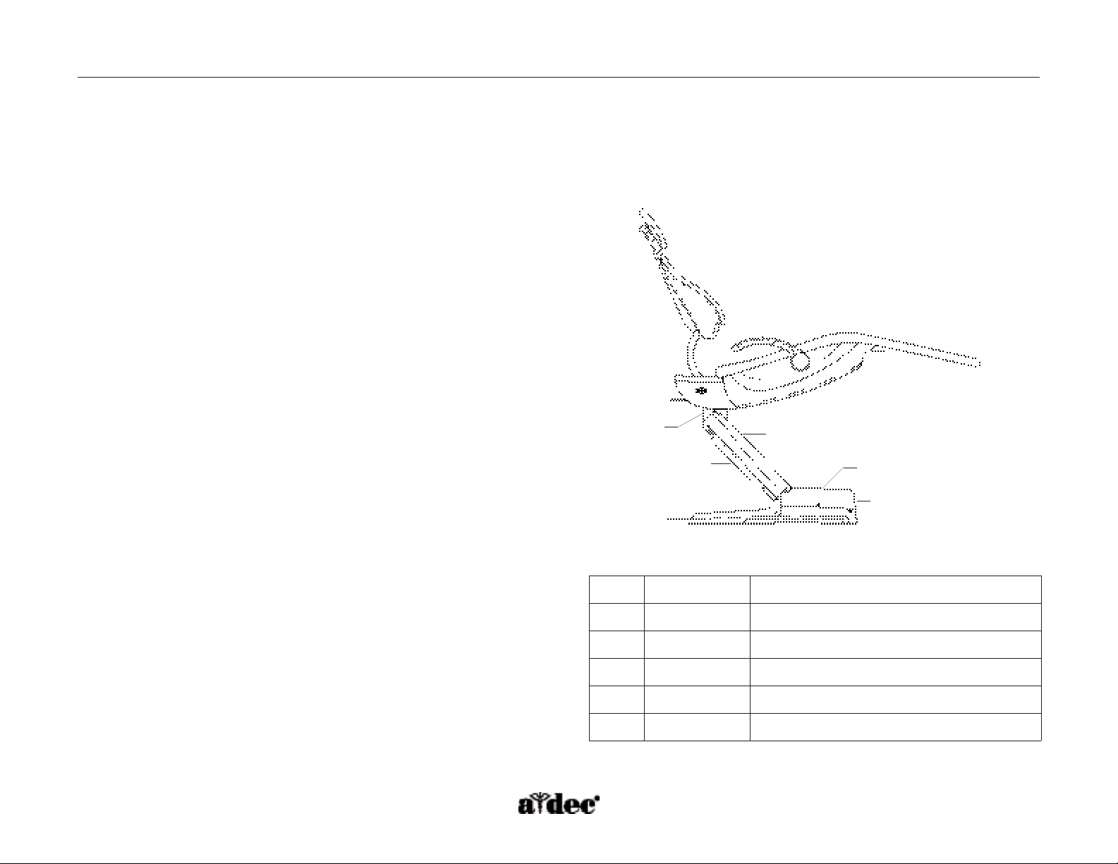
How to Remove/Install Chair Covers
The A-dec 511 chair motor pump, lift arm, and stop plate covers should be removed in the following order.
Motor Pump Cover
Remove -Remove screw from each side and lift up.
Install - Replace cover,and attach with two screws.
Lift Arm Cover
Remove -Pull one side of the cover until it releases from the lift arm.
Install - Align one side of the cover with the lift arm and snap into place.
Ensure both sides are firmly attached.
Stop Plate
Remove -Pull one side of the cover until it releases from the lift arm.
Install - Slide one side of the cover over the post on the lift arm and attach.
Swivel Cover
Remove -Pull one side of the cover and pull off.
Install - Align the cover with the holes on one side and snap cover into
place by applying pressure to the center of the cover.
Item #
Part Number
Description
1
62.0080.00
Motor pump cover
2
62.0081.00
Lift arm cover
3
62.0084.00
Stop plate cover
4
62.0122.00
Swivel cover
5
62.0101.00
Motor pump cover plug
4
3
2
5
1
Figure 13. A-dec 511 chair covers.
Page 4

Page 20 85.0816.00 Rev A 2004-11 (PCA 04002.12)
Flow Diagram A-dec Service Guide, Vol. II
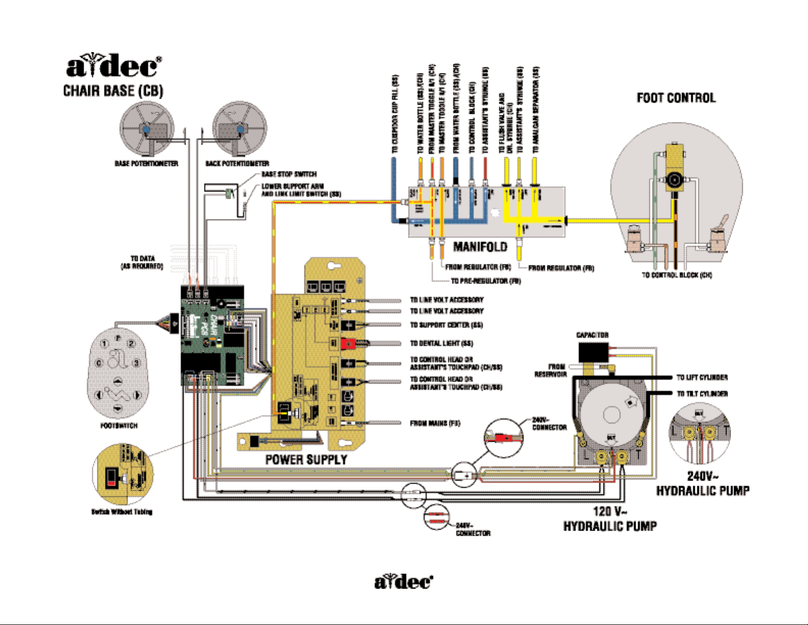
Chair Flow Diagram
This flow diagram details both electrical and plumbing information for servicing and troubleshooting the A-dec 511 chair. It is located on the
motor pump cover.This diagram includes the air electric switch,motor pump connections, and potentiometers.
Page 5
85.0816.00 Rev A 2004-11 (PCA 04002.12) Page 21
Air electric switch connects the
power supply to pilot air.
Chair Flow Diagram
Page 6

Page 22 85.0816.00 Rev A 2004-11 (PCA 04002.12)
Chair Circuit Board A-dec Service Guide, Vol. II
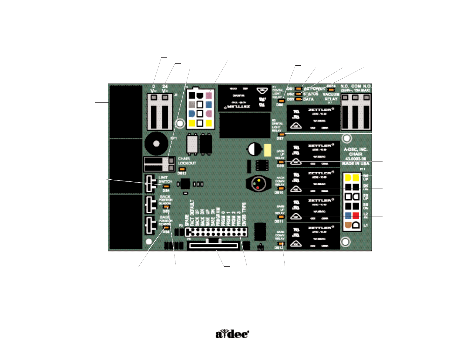
How to Identify the Chair Circuit Board Components
(P/N 90.1072.00)
The chair circuit board contains the relays necessary for controlling the chair’s motor
pump and solenoids.The chair circuit board is equipped with test points that allow
manual chair operation without a footswitch or a touchpad.
The chair circuit board is located on the power supply.To access the circuit board,
remove the pump cover. Use the LEDs located on the circuit board to determine if the
chair is functioning correctly.
Item # Description
1
P7, P8, P9 - Data line ports
2
DS4 - Stop switch LED (limit switch) and
P10 connector
3
DS5 - Back potentiometer LED and P1 connector
4
DS6 - Base potentiometer LED and P2 connector
5
P5 - Footswitch connector
6
P3 - Test points
7
DS12 - Base down LED and relay
8
DS11 - Base up LED and relay
9
DS10 - Back down LED and relay
10
DS9 - Back up LED and relay
11
DS1 - AC power LED
12
DS2 - Status LED
13
DS3 - Data LED
14
DS13 - Chair lockout LED and terminal strip J1
15
J2 - Ø VAC terminal strip (output)
16
J2 - 24 VAC terminal strip (output)
17
P4 - Input power and dental light connector
18
J3 - Vacuum relay output terminal strip
19
P11 - Pump motor and solenoid connector
20
DS8 - Dental light relay
21
DS7 - Dental light relay
Page 7
85.0816.00 Rev A 2004-11 (PCA 04002.12) Page 23
A-dec Service Guide, Vol. II Chair Circuit Board
Figure 14. A-dec 511 chair circuit board components.
1
11
12
13
14
4
3
5
6
7
8
9
10
21
18
16
15
17
20
2
19
Page 8

Page 24 85.0816.00 Rev A 2004-11 (PCA 04002.12)
Chair Circuit Board A-dec Service Guide, Vol. II
Factory Default Routine
When a new circuit board is installed in the chair, the circuit board needs to run the factory default routine to learn the range of motion of the
chair.The routine sets the base and back upper limits, calculates new presets based on actual range of motion of the chair, and verifies that the
potentiometers work.
To start the factory default routine, place the “spare” jumper in the factory default position on the P3 test points of the chair circuit board.
When running the factory default routine the chair:
• Moves base down
• Moves base up
• Moves back down
• Moves back up
• Moves base and back to Position 0, and
• Beeps three times.
NOTE: The jumper must remain in the factory default position to complete the factory default routine.
The status LEDs on the standard and deluxe touchpads and the chair circuit board double blink
while the factory default routine is running and after the routine is complete.
Page 9

85.0816.00 Rev A 2004-11 (PCA 04002.12) Page 25
A-dec Service Guide, Vol. II Chair Circuit Board
LED Identification
LED Status Description
DS1 - AC power LED Off
Green, steady
No 24 VAC power, tripped circuit breaker, power supply turned off,
no line voltage
24 VAC at the terminal strip
DS2 - Status LED Off
Green, steady
System is not functioning, no power or circuit board has failed
Normal operation
DS3 - Data LED Off
Green, steady
Green, blinking
No DCS communication, not connected to the DCS, or DCS has failed
Detects active DCS
Valid DCS message
DS4 - Chair limit switch Off
Red
Closed, (normal)
Open, (activate)
DS13 - Chair lockout Off
Red
Open, (normal)
Closed, (activate)
DS5 + DS6 - Chair potentiometers Off Potentiometer:
• Not connected or bad connection
• Moving in wrong direction
• Limited range of motion, or
• Cable is not on wheel.
Yellow, steady Normal operation
Yellow, fast blink Upper end of travel
DS9, DS10, DS11, DS12 - Chair
relay LEDs
Off
On
Relay is off
Relay is on
DS7, DS8 - Dental light relay LEDs Off
On
Relay is off
Relay is on
DS14 - Vacuum relay LED Off
On
Relay is off
Relay is on
Page 10

Page 26 85.0816.00 Rev A 2004-11 (PCA 04002.12)
Power Supply A-dec Service Guide, Vol. II
Chair Power Supply
The 300-watt power supply comes standard with the A-dec 511 chair. It is located in the motor pump area of the chair.The total available
auxiliary load is a maximum of 4 Amps.
Circuit Breaker Function
CB 1
Mains
CB 2
Mains
CB 3
Support side arm (side support arm)
CB 4
Dental light
CB 5
Assistant’s arm, control head (delivery
system), and chair circuit board
Figure 15. Chair power supply circuit breaker identification
CB 4
CB 3
CB 1
CB 2
CB 5
Page 11

85.0816.00 Rev A 2004-11 (PCA 04002.12) Page 27
A-dec Service Guide, Vol. II Hydraulic System
How the Hydraulic System Operates
The hydraulic system deactivates automatically at the upper and lower extremes of travel.The system is leak-free during transportation, storage,
and operation.The hydraulic system consists of:
• Hydraulic fluid reservoir
• Hydraulic cylinders
• Motor-driven hydraulic pump with solenoids
Hydraulic Fluid Reservoir
The hydraulic fluid reservoir is located in the lift arm of the chair under the stop plate cover.
The fluid level in the reservoir can be seen through the sides of the reservoir and is serviced
via a top fill cap.The hydraulic system holds 40 ounces (2.5 pints [1.18 l]) of hydraulic fluid.
• Place the chair in the full base and back up position, when filling the reservoir.
• The reservoir should be filled to the green Max line. Do not over fill. Cycle the chair
after the reservoir is filled.
Figure 16. Identifying the hydraulic fluid
reservoir fluid levels.
Page 12

Page 28 85.0816.00 Rev A 2004-11 (PCA 04002.12)
Hydraulic System A-dec Service Guide, Vol. II
Hydraulic Cylinders
The hydraulic cylinders operate during the Base Up and Back Up functions. Springs and gravity retract the piston during base and
Back Down functions.
The chair seat travels vertically from a low point of 13.5" (343 mm) to a high point of 31.5" (800 mm) above the floor.
Motor-driven Hydraulic Pump
The hydraulic pump takes hydraulic fluid from the reservoir and pressurizes it to extend the chair lift and tilt hydraulic cylinders for back and
base up functions.The bi-directional pump rotates one direction for Base Up and one direction for Back Up.The solenoids mounted to the
pump assembly gate hydraulic fluid from the two cylinders. Depending on the chair function, the controller selects which solenoid-actuated
manifold valves are opened or closed.The 100-120 VAC pump and 220-240 VAC pump are equipped with an automatic reset 110°C (230°F)
thermostat.There are no serviceable parts on the hydraulic pump other than the solenoids.
NOTE: The speed of the chair is not adjustable.
Figure 17. Hydraulic cylinder operation.
Page 13

85.0816.00 Rev A 2004-11 (PCA 04002.12) Page 29
A-dec Service Guide, Vol. II Hydraulic System
Capacitor
100 VAC (P/N 041.642.00)
110 - 120 VAC (P/N 041.643.00)
220 - 240 VAC (P/N 041.644.00)
The capacitor is energized during chair Base Up or Back Up functions.
Figure 18. A-dec 511 chair capacitor located on the motor pump assembly. (A) capacitor
A
Page 14

Page 30 85.0816.00 Rev A 2004-11 (PCA 04002.12)
Hydraulic System A-dec Service Guide, Vol. II
Solenoids
100 - 120 VAC (P/N 90.1070.00)
220 - 240 VAC (P/N 90.1071.00)
The two chair solenoids, one for each cylinder, control the down functions of the chair.The solenoid (A) controls the base down function and the
solenoid (B) controls the back down function.The base and back down solenoids are interchangeable, and available in two voltage ranges.
How to Test Solenoids
To check for a failed solenoid, test the solenoids using a volt/ohm meter or
magnetic pull test.
• Magnetic pull - Hold a paper clip loosely in your hand and activate the
solenoid by pressing Base Down or Back Down on the footswitch or
touchpad. If there is a pull, the solenoid is being activated.
• Coil resistance - Disconnect the solenoid power at the 2-position
connector. Place on Ohm meter probe on each of the solenoid
connector terminals.
100 - 120 VAC = 177 Ohms ± 18 Ohms
220 - 240 VAC = 845 Ohms ± 85 Ohms
NOTE: If the solenoid is hot, then the resistance will read higher.
ELECTRICAL WARNING: The solenoid coils are powered by line voltage
(100, 120, or 240 VAC). Failure to unplug the
chair may result in serious injury from
electrical shock.
WARNING: The base or back system must be depressurized prior to
removing the solenoid.To depressurize base or back system,
remove the failed solenoid coil and replace with the operating
solenoid coil. Lower the chair base and back.
NOTE: When replacing a solenoid, wipe up any oil, and replace existing
O-rings on the solenoid base.
Figure 19. A-dec 511 chair solenoids located in the motor pump
assembly. (A) base down solenoid; (B) back down solenoid
B
A
Page 15

85.0816.00 Rev A 2004-11 (PCA 04002.12) Page 31
A-dec Service Guide, Vol. II Potentiometers
How the Potentiometer Operates
The potentiometer and cable assembly is a simple, accurate unit, which eliminates position float.“Float”is seen as a slight change or variation in
the pre-programmed positions.The same potentiometer assembly is used for both lift and tilt requirements. If a potentiometer should fail, the
limp-along feature allows the operator to position the chair for one second intervals by pushing the manual control buttons on the
touchpad or footswitch.
Figure 20. Location of the chair Base Up and Back Up potentiometers. (A) Base Up potentiometer; (B) Back Up potentiometer
A
B
Page 16

Page 32 85.0816.00 Rev A 2004-11 (PCA 04002.12)
Chair Stop Plate A-dec Service Guide, Vol. II
How the Chair Stop Plate Operates
(P/N 90.1095.00)
The chair stop switch stops chair movement when the stop plate is pressed. Should anything inadvertently become lodged under the chair, press
Base Up on the touchpad or footswitch to raise the chair so the object can be removed. As long as pressure is applied to the stop plate, the chair
will not move down.
The stop plate has only one switch.The switch and all other parts snap into place for easy removal or replacement. No tools are required.
Be sure to power off the chair and disconnect it from its power source before replacing the stop
switch. Cable tie the wires to the lift arm to prevent kinking and pinching.
Chair Bump-Up Feature
The chair stop plate and the assistant’s arm, trigger the chair to move
upwards if it was moving down when the stop plate switch was activated.
Figure 21. A-dec 511 chair stop plate. (A) stop switch
A
Page 17

85.0816.00 Rev A 2004-11 (PCA 04002.12) Page 33
A-dec Service Guide, Vol. II Chair Adjustments
How to Adjust the Chair
Swivel Brake
The chair can rotate to any position within 30° either side of center.The chair
swivel brake restricts rotation of the chair to keep the chair from moving.To
engage the brake, push the brake lever firmly to the left.To release the swivel
brake, push the brake lever to the right.
Tension Adjustment
If the chair swivels left or right with the brake engaged, or if it is difficult to
move with the brake disengaged, adjust the swivel brake tension.To adjust the
tension, use a hex key and turn the tension adjustment screw clockwise to
increase brake friction or counterclockwise to decrease brake friction.
If proper adjustment cannot be obtained through rotation of the hex key,
replace the brass brake pad by removing the brake handle and using a hex key
to disengage the pad. Remove the old pad and replace with new one. Replace
the brake handle and handle retainer.
NOTE: The shipping pin can be reinstalled in the chair if swivel feature
is not desired.
Figure 22. Chair swivel.
Figure 23. Swivel brake tension adjustment. (A) tension
adjustment screw
Engaged Released
A
Page 18

Page 34 85.0816.00 Rev A 2004-11 (PCA 04002.12)
Chair Adjustments A-dec Service Guide, Vol. II
Headrest
The headrest adjustment lever allows the headrest to be adjusted using one hand.When the lever is released, the headrest holds its position.
Drift Adjustment
If the headrest drifts downward, or if it is difficult to move up or down, the glide bar tension needs to be adjusted. To adjust the tension, use a
hex key and turn the tension adjustment screw clockwise to increase friction or counterclockwise to decrease friction.
Figure 24. Headrest adjustments. (A) headrest adjustment lever;
(B) glide bar; (C) glide bar tension adjustment
B
A
C
Page 19

85.0816.00 Rev A 2004-11 (PCA 04002.12) Page 35
A-dec Service Guide, Vol. II Chair Troubleshooting
How to Troubleshoot the Chair
Tips and troubleshooting information are listed in the table to assist in diagnosing chair problems.
These tables are not intended to cover every situation, but do include the most common problems that
may be encountered.
Problem Possible Cause Action
No power to chair or unit, office still
has power
The chair is unplugged Plug chair in to power source.
The power button is in Off position Press in power button.
No pilot air to power supply Verify master On/Off toggle is in the On position. Verify pilot air is connected to
the power supply and air manual shutoff valve is fully open.
Power supply circuit breaker is tripped or power
supply has failed
Check circuit breaker and reset. If the circuit breaker trips again, disconnect all
power cables from the power supply then reconnect one at a time observing
which one causes the circuit breaker to trip – that will identify the problem circuit.
Circuit board has failed Check chair circuit board power LED.If not illuminated, check connections and
replace circuit board, if needed.
No base and back up function, the motor
relay clicks and LED illuminates
Capacitor is disconnected or has failed Verify the base up or back up relay clicks and the LED (DS10 or DS12) on the
chair circuit board is illuminated. Check capacitor connections. Replace the
capacitor with one of correct voltage.
No base or back down, relay clicks and
LED illuminates
Solenoid has failed • Check for magnetic pull while operating base or back down function.
• Check for correct resistance value at solenoid connector:
100 - 120 VAC 177 Ohms ± 18 Ohms
220 - 240 VAC 845 Ohms ± 85 Ohms
• Replace solenoid.
WARNING: Depressurize system before replacing the failed solenoid.To
operate chair to full Base Down and Back Down, switch the
good solenoid coil for the failed one and operate the function
until full down position is reached.
Back down is pressed, base moves or
base down is pressed, back moves
The base and back solenoid connectors
are switched
Connect the solenoids correctly.
Base or back moves up for only one
second, no automatic buttons work
(limp-along feature)
DS5 - (back) not illuminated
DS6 - (base) not illuminated
The potentiometer for that movement has failed,
is disconnected, or is not turning
Check sensor electrical connections, wiring and the pull cable. Replace as an
assembly if damaged.
Page 20

Page 36 85.0816.00 Rev A 2004-11 (PCA 04002.12)
Chair Troubleshooting A-dec Service Guide, Vol. II
Problem Possible Cause Action
Base Down and programmed positions
do not work, but the chair back functions,
A-dec status icon is flashing, DS4 red
LED on the chair circuit board
is illuminated
Stop switch for chair, or support side arm is
activated or has failed
Check for obstruction under chair, or support side arm and remove.
• Disconnect the chair stop switch connector at the chair circuit board
and insert the jumper. If the red LED (DS4) goes out and the chair
works, then the chair circuit board is functioning normally.
• Remove the spare jumper from the chair circuit board, and reconnect
the chair stop switch connector. Disconnect the support side stop
switch wiring from the chair stop switch connector and insert the
jumper. If the red LED (DS4) goes out and the chair works, replace the
side support stop switch. If the red LED (DS4) stays on, then replace
and/or repair the chair stop switch assembly.
No chair movement from a touchpad,
status icon is illuminated
Touchpad DCS is interrupted Verify the chair operates with the footswitch or the test points on the chair
circuit board.Then check the data line connection, and if needed, replace the
data line connected to the touchpad.Verify the data light illuminates.
No chair movement from the touchpad,
status icon is not illuminated
Faulty touchpad Verify AC power to chair and that chair can be operated from the footswitch or
other touchpad.Verify 24 VAC to touchpad circuit board. If 24 VACs present,
replace the touchpad.
Faulty touchpad power cable Verify the AC power LED (DS1) is illuminated on the delivery system circuit
board or chair circuit board.Verify the touchpad functions normally by using an
external touchpad power cable. Replace the touchpad power cable, if needed.
Base or back will not move to full up
position, LED for that function is flashing
Potentiometer connections are switched Connect potentiometers to correct chair circuit board locations.
P1 — Back potentiometer
P2 — Base potentiometer
Unable to change chair
programmed positions
Potentiometer connections are switched Connect potentiometers to correct board locations.
P1 — Back potentiometer
P2 — Base potentiometer
The potentiometer for that movement has failed,
is disconnected, or is not turning
Check sensor electrical connections, wiring, and the pull cable. Replace as an
assembly if damaged.
Page 21

85.0816.00 Rev A 2004-11 (PCA 04002.12) Page 37
ELECTRICAL WARNING: The solenoid coils are powered by line voltage (100,100 - 120, or 220 - 240 VAC). Failure to unplug the chair may
result in serious injury from electrical shock.
WARNING: The hydraulic system must be depressurized before removing the solenoid.To depressurize the hydraulic system, remove the
failed solenoid coil and replace with the operating solenoid coil. Lower the chair base and back.
NOTE: When replacing a solenoid, wipe up any oil, and replace existing O-rings on the solenoid base.
Problem Possible Cause Action
The three tap feature used at installation
no longer works
The three tap feature is disabled The three tap feature is disabled when a powered touchpad has been connect-
ed to the DCS, a footswitch is installed or the test points have been used to
move the chair.
To re-enable the three tap feature:
• Disconnect the DCS touchpad connections
• Disconnect the footswitch
• Cycle power to the chair
No or limited chair functions
from footswitch
Footswitch connector/wiring is damaged Check that chair operates from a touchpad or the test points (P3). Replace the
footswitch connector and/or wiring assembly.
Footswitch membrane is damaged Check footswitch connectors and membrane, replace as necessary.
The chair makes a noise when Base Up
or Back Up is pressed
Chair is low on hydraulic fluid Remove motor pump,lift arm, and stop plate covers. Check fluid level with
chair base and back up by viewing the reservoir from the back of the chair.Add
fluid to maximum level.
Hydraulic hose from reservoir to pump
is pinched
Inspect all hydraulic hoses, ensure they are not being pinched in any position. If
the supply tube between the pump and the reservoir is kinked, order and install
kit P/N 90.1100.00.
Motor pump has as obstruction or is damaged If chair continues to growl, lower base and add up to 4 oz (.12 l) more fluid. If
noise continues, replace motor assembly.
A button on a touchpad does not work,
but function works from other location(s)
Faulty touchpad Verify the touchpad circuit board is snapped into the plastic cover.
Verify the function does work from other locations (footswitch, chair test points,
light switches, cuspidor buttons), then replace the touchpad.
The automatic positions do not work, the
A-dec logo is flashing, double blinks
The jumper is in the factory default position on
the chair circuit board test points (P3)
Move the jumper from the factory default position to the “spare”position on the
test points.
The chair will not move up from the full
base down with the foot control under
the stop plate
The automatic chair lockout feature has been
activated by an air signal from the
foot control
Remove the motor pump cover and disconnect the delivery system data line.
Turn the chair power OFF and then ON again. The chair circuit board test
points or footswitch can now be used to raise the chair and remove the foot
control from under the lift arm.
A-dec Service Guide, Vol. II Chair Troubleshooting
Page 22

Page 38 85.0816.00 Rev A 2004-11 (PCA 04002.12)
Chair Troubleshooting A-dec Service Guide, Vol. II
Problem Possible Cause Action
Chair brake does not hold Brake needs adjusting or the pad needs replacing Adjust or replace brake components as necessary.
Chair glide bar slides down or is difficult
to lift up
Glide bar needs adjusting or the wear pads
needs replacing
Adjust or replace glide bar components as necessary.
Headrest will not lock or is difficult
to unlock
Headrest needs adjustment or needs replacing Operating lever may be too tight, adjust for slight play in movement.
If the headrest still does not work correctly, replace it as an assembly. No field
service to locking components.
Armrest(s) will not lock in up position or
are difficult to operate
Armrests may have an obstruction or
be damaged
Check for obstruction or damage. Replace as an assembly.
Circuit breaker 1 or 2 opens Electrical short in a module Remove all connections from the power supply.
Reset the circuit breaker.
Reconnect modules one at a time until the circuit breaker trips.
Review troubleshooting for that module.
Circuit breaker will not reset Faulty circuit breaker Replace the power supply.
 Loading...