

Page 1
85.0816.00 Rev A 2004-11 (PCA 04002.12) Page 39
A-dec Service Guide, Vol. II Doctor’s Side
The doctor’s side of the A-dec 500 system includes both the Traditional (model 532)
and Continental
®
(model 533) delivery systems, the front-mount monitor (model 531),
and self-contained water system.
The delivery system supplies and regulates the air and water used to operate dental
handpieces, syringes, and accessories. The A-dec 532 and 533 delivery systems have
been designed to mount only to the A-dec 511 chair and communicate with the entire
A-dec 500 product line through the Data Communications System (DCS).
This section of the A-dec Service Guide,Vol.II contains the electrical and plumbing flow
diagrams for the delivery systems, along with illustrations of exploded parts,
troubleshooting and adjustments for all of the doctor’s side modules.
For information on service parts, see the Genuine A-dec Service Parts Catalog, or contact
A-dec customer service.
Page 2
Page 40 85.0816.00 Rev A 2004-11 (PCA 04002.12)
Delivery System Components A-dec Service Guide, Vol. II
A-dec 500 Delivery System Components
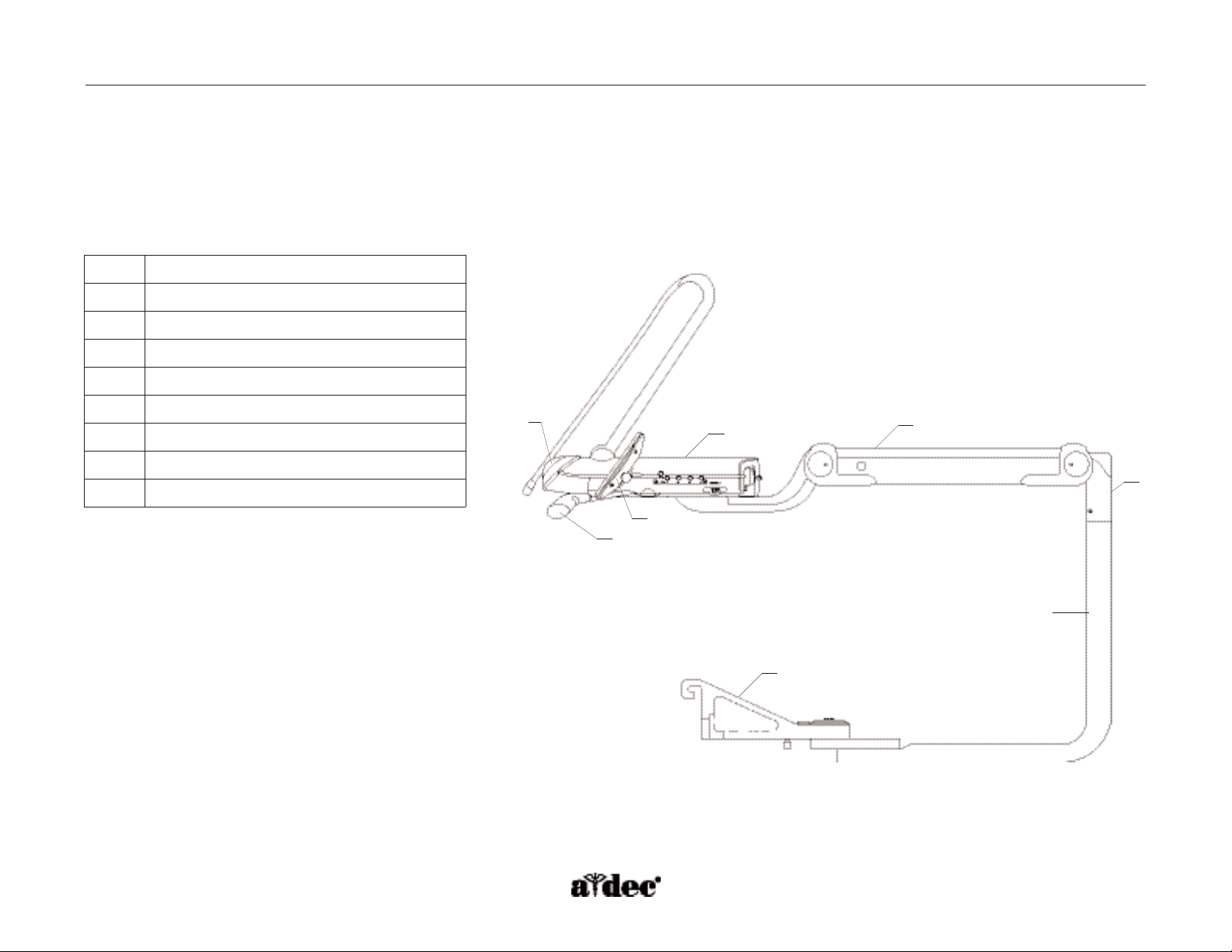
The A-dec 500 delivery systems and front-mount monitor both mount to the A-dec 511 chair.This mounting structure provides left/right
capabilities for both the delivery system and the monitor.
Item # Description
1
Delivery system cover
2
Delivery system front cover
3
Touchpad
4
Brake handle
5
Flexarm
6
Front-mount arm
7
Flexarm hub
8
Front-mount casting
Figure 25. Delivery system and front-mount arm components.
1
6
3
2
7
5
4
8
Page 3
85.0816.00 Rev A 2004-11 (PCA 04002.12) Page 41
A-dec Service Guide, Vol. II Delivery System Components
Internal Control Components
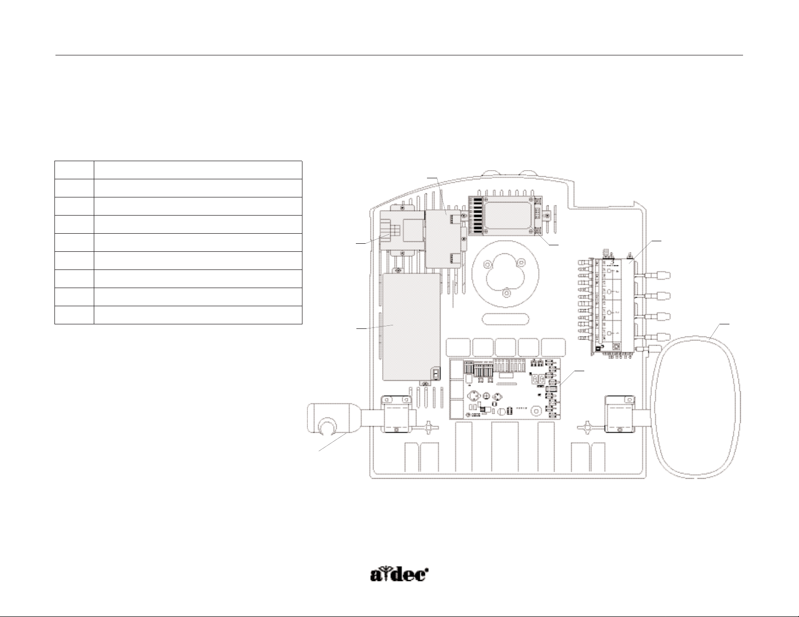
The A-dec 532 and 533 delivery systems feature a structural platform in the base of the control head.This metal mounting grid allows easy
attachment of component parts and extra control modules required by accessories.
Figure 26. Identification of the internal control components mounted on the structural platform.
Item # Description
1
Scaler control module
2
Electric micromotor control module
3
Curing light control module
4
Camera control module
5
Control block
6
Delivery system circuit board
7
Touchpad
8
Accessory holder
7
6
5
4
3
1
2
8
Page 4

Page 42 85.0816.00 Rev A 2004-11 (PCA 04002.12)
Page 5
85.0816.00 Rev A 2004-11 (PCA 04002.12) Page 43
A-dec Service Guide, Vol. II Delivery System Covers
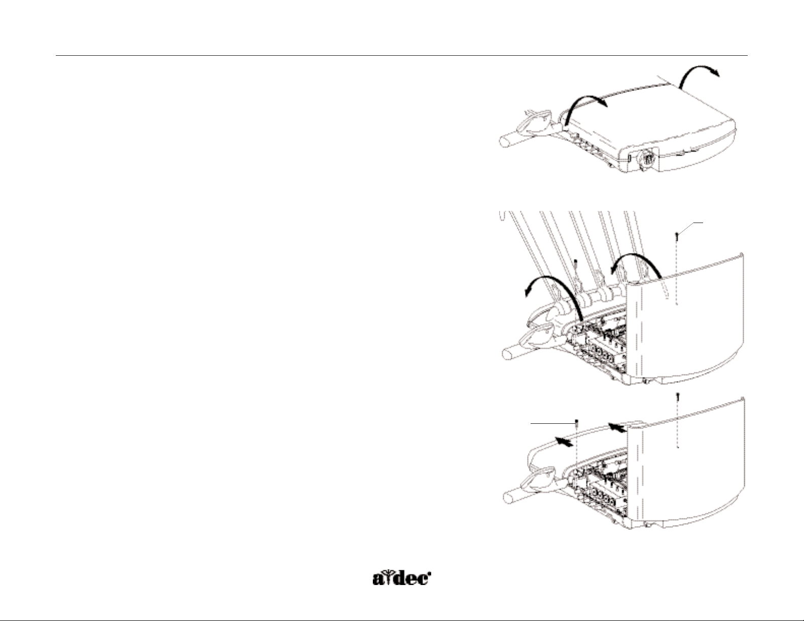
How to Remove the Delivery System Covers
The delivery system covers are designed for easy access to control components.
Delivery System Cover
Lift up on the center tab on the back of the delivery system cover and then, lift up the tabs
on both sides of the delivery system cover and open the cover. Pinch the hinge brackets at
the cover base to remove the cover.
Delivery System Front Cover — Continental
Move the whips forward, and remove the two screws holding the delivery system front cover
in place. Open the front cover carefully, until the lanyard is taut.
CAUTION: Remove handpieces from the delivery system before opening the delivery
system front cover.
Delivery System Front Cover — Traditional
Remove the two screws holding the delivery system front cover in place. Slide the front
cover forward and lift up.
Figure 27. Open the delivery system cover.
A
A
Figure 28. Open the delivery system front covers.
(A) screw
Page 6

Page 44 85.0816.00 Rev A 2004-11 (PCA 04002.12)
Flow Diagram A-dec Service Guide, Vol. II
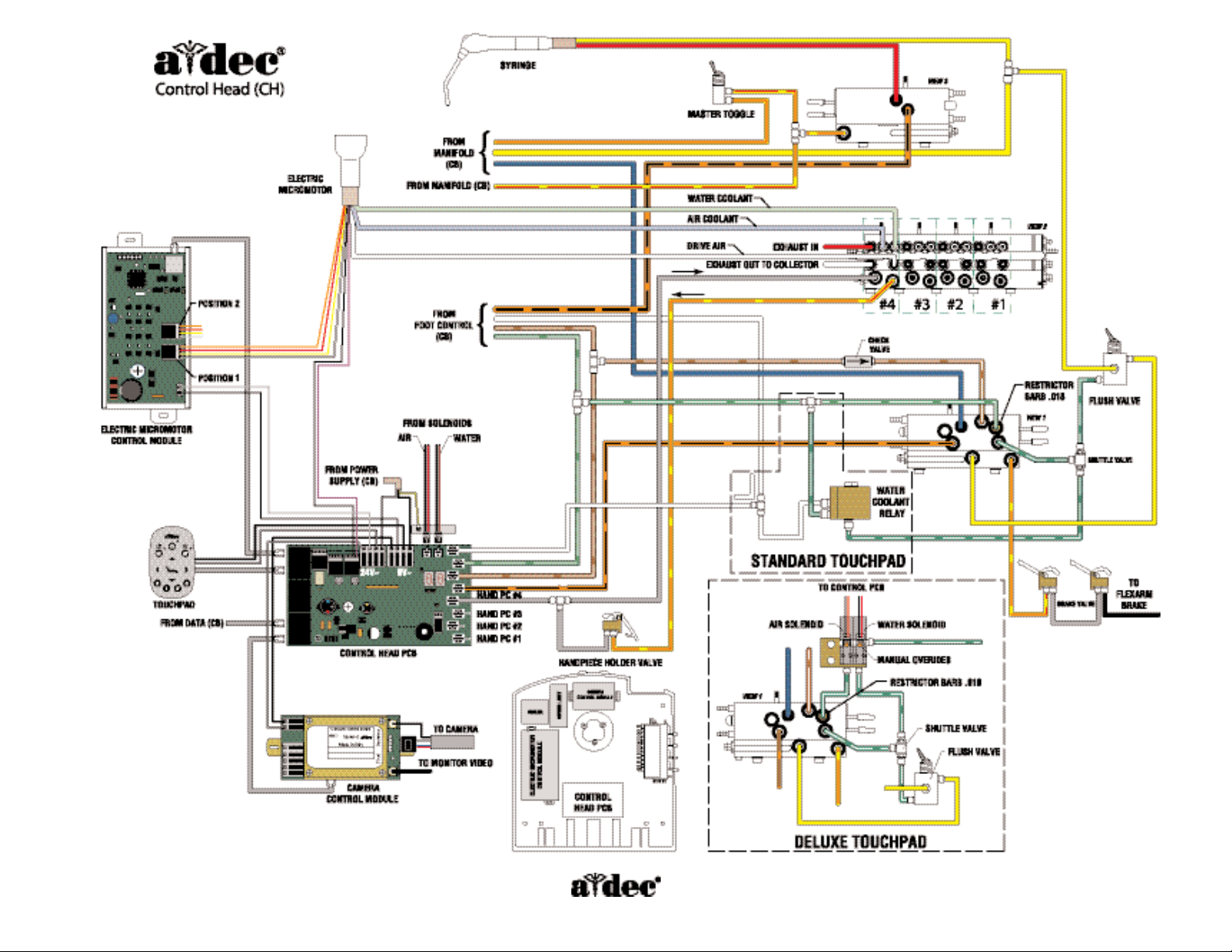
Delivery System Flow Diagram
This flow diagram details both electrical and plumbing information for servicing and troubleshooting A-dec 532 and 533 delivery systems. It is
located on the inside cover of the delivery system.This diagram includes the plumbing and wiring for the standard touchpad, deluxe touchpad,
camera, and electric micromotor.
Page 7
85.0816.00 Rev A 2004-11 (PCA 04002.12) Page 45
Page 8

Page 46 85.0816.00 Rev A 2004-11 (PCA 04002.12)
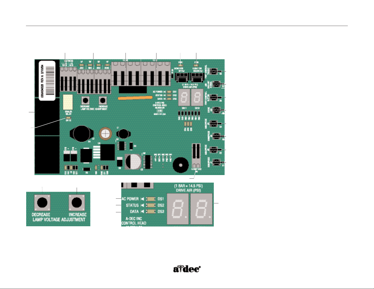
How to Identify Delivery System Circuit Board Components
(P/N 90.1076.00)
The delivery system circuit board has a wide range of functionality with a built-in
intraoral light source, drive air pressure digital readout, and status LEDs.Transducers
translate air signals to electronic signals, communicating with the touchpad and other
components when a handpiece is ready for use.
Item # Description
1
P1, P2, P3 - Data line ports (DCS)
2
J6 - Scaler power terminal strip
3
J4, J5 - Intraoral light source strip and LEDs DS7,
DS8, DS9, DS10
4
J2 - 24 VAC terminal strip
5
J2 - Ø VAC terminal strip
6
DS6 - Air coolant solenoid LED and connector
7
DS5 - Water coolant solenoid LED and connector
8
X8 - Water coolant signal transducer
(foot control toggle)
9
X7 - Air coolant signal transducer
10
X6 - Accessory button (foot control)
signal transducer
11
X5 - Drive air signal transducer
12
X4 - Handpiece 4, holdback transducer
13
X3 - Handpiece 3, holdback transducer
14
X2 - Handpiece 2, holdback transducer
15
X1 - Handpiece 1, holdback transducer
16
J3 - Handpiece 5, terminal strip
17
DS11, DS12 - Drive air LED display
18
DS1 - AC Power LED
19
DS2 - Status LED
20
DS3 - Data LED
21
S2 - Increase intraoral light source voltage adjustment
22
S1 - Decrease intraoral light source voltage adjustment
23
DS13 - Scaler relay LED
Delivery System Circuit Board A-dec Service Guide, Vol. II
Page 9
85.0816.00 Rev A 2004-11 (PCA 04002.12) Page 47
Figure 29. Components of the delivery system circuit board.
1
17
18
19
20
22
21
A-dec Service Guide, Vol. II Delivery System Circuit Board
23
2
3 4 5 6
7
8
9
10
11
12
13
14
15
16
Page 10

Page 48 85.0816.00 Rev A 2004-11 (PCA 04002.12)
Page 11
85.0816.00 Rev A 2004-11 (PCA 04002.12) Page 49
A-dec Service Guide, Vol. II Illustrated Parts
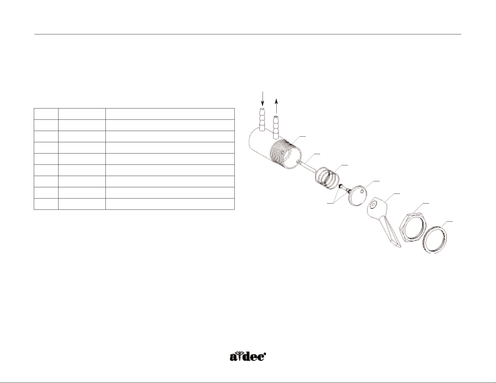
Handpiece Flush Toggle
(P/N 33.0168.00)
The flush toggle is located on the back of the delivery system. It uses holdback air to
operate the handpiece flush function. When the momentary valve is on, the
holdback air is exhausted and air signal is sent toward the water cartridge.
If the handpiece is in the holder (holdback active), the flush will not be activated.
If the handpiece is out of the holder (holdback exhausted), the flush will operate.
Item #
Part Number
Description
1
006.009.00
Hex nut 15/32-32" x 9/16 x 3/32"
2
33.0036.02
Momentary toggle lever
3
030.003.02
O-ring, .056 ID x .060 W, pkg 10
4
013.076.00
Spring, compression, .360 OD x .35 FL
5
011.038.01
Straight pin, .062 Dia x .430 Lg, SS, pkg 5
6
023.004.03
Barb, 1/8" x 10-32, pkg 10
7
004.005.02
Flat nylon washer, .187 ID,pkg 10
8
33.01470.00* Stem
9
80.5025.00* Spacer
1
2
9
8
3
4
5
6
7
Figure 30. Identification of the handpiece flush
toggle components.
* Item not for sale.
Page 12
Page 50 85.0816.00 Rev A 2004-11 (PCA 04002.12)
Illustrated Parts A-dec Service Guide, Vol. II
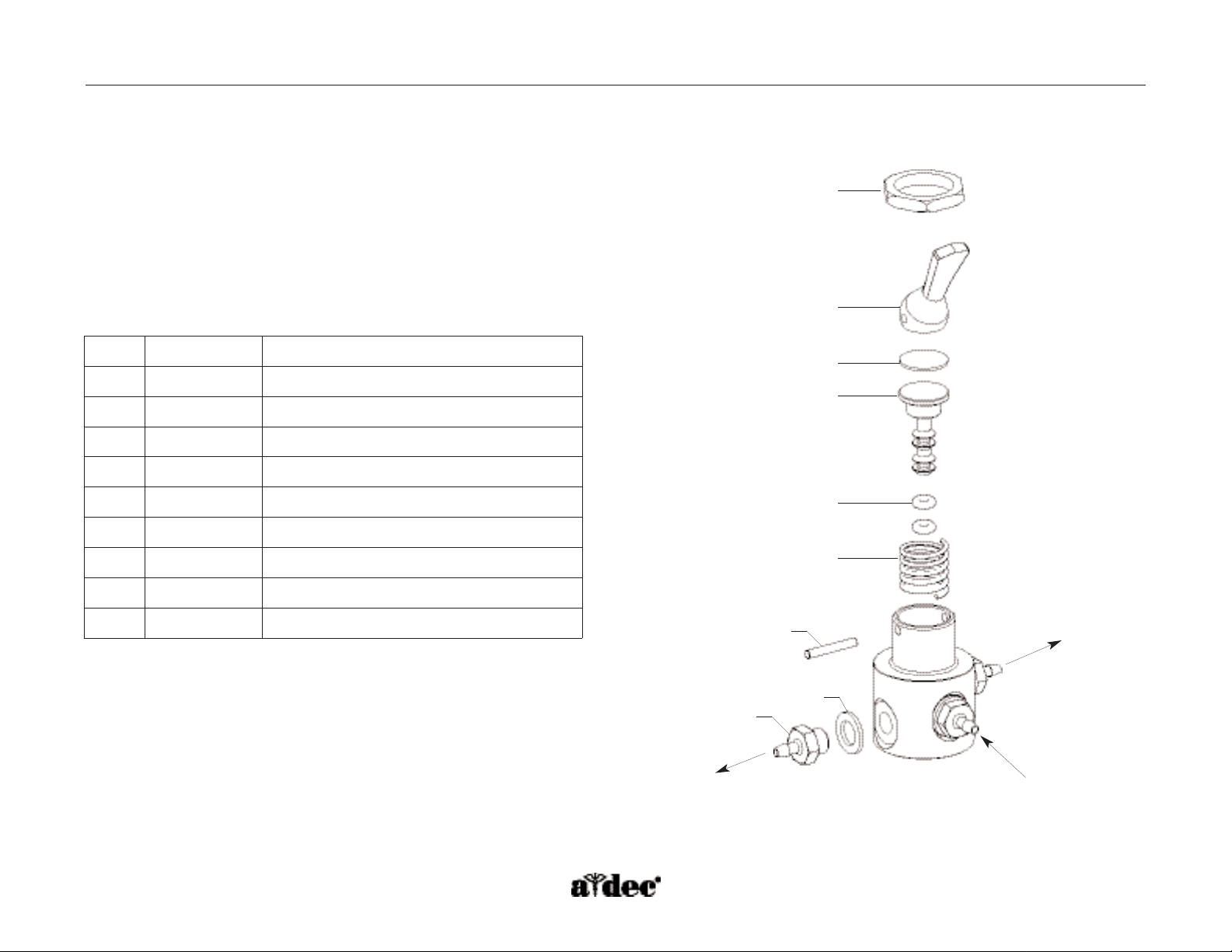
Master On/Off Toggle
(P/N 33.0048.04)
The master On/Off toggle is located on the side of the delivery system.The toggle operates with unregulated air and supplies air to the chair
air/water manifold and the control block, for holdback air.
Item #
Part Number
Description
1
33.0050.00
Round toggle valve body
2
011.038.01
Straight pin, .062 Dia x .430, pkg 5
3
22.0040.00
Compression spring, .300 OD x .40
4
030.001.02
O-ring, pkg 10
5
29.0840.00
Valve stem with O-rings, 3-way
6
22.0462.02
Plastic toggle valve lever,Surf 4
7
006.009.00
Hex nut, 15/32-32" x 9/16 x 3/32"
8
006.069.00
Knurl nut, 15/32-32"
1
2
3
4
5
6
7
8
Figure 31. Identification of the master On/Off toggle components.
Page 13

85.0816.00 Rev A 2004-11 (PCA 04002.12) Page 51
A-dec Service Guide, Vol. II Illustrated Parts
Whip Assembly
(P/N 77.0291.01)
The whip return tension can be adjusted by placing the bail in two
different locations.
The whip cover is removable for easy handpiece tubing replacement.To reinstall
the whip cover,fully extend the whip and attach the back starting at the ball end
and work toward the handpiece end.
Item #
Part Number
Description
1
013.123.00
Spring, extension, .460 OD x 2.473
2
77.0155.00 Bail
3
001.033.00
Socket head screw 6-32" x 3/8" stainless steel
4
77.0063.00
Whip cover,Surf 4
Figure 32. Whip assembly with the adjustable bail position for
(A) greater tension or (B) lesser tension.
1
2
3
4
A
B
Page 14

Page 52 85.0816.00 Rev A 2004-11 (PCA 04002.12)
Illustrated Parts A-dec Service Guide, Vol. II
Item #
Part Number
Description
1
23.0872.01
Syringe tip, pkg 5
2
035.048.01
O-ring, pkg 10
3
034.003.01 O-ring, pkg 10
4
23.1112.00
Retainer nut
5
23.1193.01
Screw, pkg 5
6
013.064.01
Spring, pkg 10
7
23.1232.01
Button valve, pkg 2
8
030.002.02
O-ring, pkg 10
9
23.1110.00
Terminal
10
23.1015.00 Handle
11
024.155.02 Tubing assembly, D-Surf, 7'
Autoclavable Syringe
The Continental and Traditional autoclavable syringes have serviceable air and water
button valves.The tip retaining nuts have replaceable O-rings.
WARNING: Turn OFF and bleed the system of air and water before servicing the
syringe.The use of disposable syringe tips in A-dec syringe
tip nuts is not recommended.
1
4
2
3
5
6
7
8
9
10
11
Continental
Traditional
Figure 33. Identification of the autoclavable syringe components.
Page 15

85.0816.00 Rev A 2004-11 (PCA 04002.12) Page 53
A-dec Service Guide, Vol. II Illustrated Parts
Brake Handle
The brake handle activates a replaceable microvalve, releasing pressure on the brake inside the flexarm.
Item # Part Number Description
1
77.0163.00 Brake button, Surf 6
2
013.121.00 Spring, torsion, stainless steel, .210 L, .030 W Dia
3
013.120.00 Spring, compression, .240 OD x .560
1
2
3
Figure 34. Identifying the brake handle components.
Page 16

Page 54 85.0816.00 Rev A 2004-11 (PCA 04002.12)
Illustrated Parts A-dec Service Guide, Vol. II
Accessory Holder
(P/N 99.0681.00 Standard or P/N 99.0684.00 Auto-electric)
The accessory holder is either an active or non-active position on the delivery system. It can be mounted on either side of the delivery system,
opposite the touchpad.
Auto-electric holders have a power source at the terminal for handpiece position 5 on the delivery system circuit board.
Item #
Part Number
Description
1
99.0683.00
Auxiliary holder hub, Surf 4
2
99.0686.00
Rotation stopper
3
007.023.00
Setscrew, 1/4-20 x 3/4, soc cup pt
4
99.0653.01
Syringe/saliva ejector holder,Surf 4
5
99.0648.00*
End cap for holder assembly
1
2
3
4
5
Figure 35. Identifying accessory holder components.
* Item not for sale.
Page 17

85.0816.00 Rev A 2004-11 (PCA 04002.12) Page 55
A-dec 500 Foot Control
The A-dec 500 foot control is a
foot-operated regulator. Handpieces
are operated by applying pressure on
the foot control. As pressure is applied
to the foot control, the black piston
exhaust vent seals against the poppet,
then pushes the poppet away from
the inlet seat. When the poppet is
unseated, regulated air flows through
the valve and out to the delivery
system as drive air. Regulated air is
also sent through the relay block and
to the delivery system as air coolant
signal. When pressure is released from
the foot control, the poppet reseals on
the inlet and pressure is exhausted
from the outlet side of the valve and
up through the piston.
To cuspidor cup fill
To water bottle
From master On/Off toggle
To master On/Off toggle
From water bottle
To control block
To assistant’s syringe
To flush valve and doctor’s syringe
To assistant’s syringe
To amalgam separator
Foot control P/N 38.1805.00
To delivery system
Accessory button
P/N 38.0612.00
Water coolant toggle
P/N 38.0604.00
Foot control valve
service kit
P/N 90.0593.00
Chair air/water manifold
From air filter regulator (80 psi)
From air filter regulator
(unregulated air)
A-dec Service Guide, Vol. II Flow Diagram
To air pre-regulator
To 300-watt
power supply
A/E switch
Page 18

Page 56 85.0816.00 Rev A 2004-11 (PCA 04002.12)
Illustrated Parts A-dec Service Guide, Vol. II
Item #
Part Number
Description
1
22.0110.00
Cover
2
38.0076.00
Foam liner
3
38.0237.00
Black retaining ring,, 5" OD
4
38.1802.00
2-Hole housing, Surf 6, 5/16"
5
40.0689.00
Yellow plastic indicator
6
40.0691.00
Blue plastic indicator
7
38.0610.00
Accessory button, Surf 6
8
38.0604.00
Wet/dry toggle valve, Surf 6
9
003.031.00
Phillips head screw, #4 x 1/2", zinc
10
003.022.00 Phillips head screw, #6 x 1/2", zinc
11
003.078.00 Socket head screw, 4-40 1/4" zinc
12
38.0059.02 Base, Surf 6
1
2
3
5
6
4
7
8
9
10
11
12
Foot Control
(P/N 38.1805.00)
Figure 36. Identifying the foot control components.
Page 19

85.0816.00 Rev A 2004-11 (PCA 04002.12) Page 57
A-dec Service Guide, Vol. II Illustrated Parts
Item #
Part Number
Description
1
38.0070.00
Actuator button
2
38.0075.03
Toggle lever, Surf 6
3
38.0066.00
Cap
4
22.0040.00
Spring, helical compression
5
010.056.00
Retainer spring
6
011.016.00
Pin
7
38.0072.03
Holder, Surf 6
8
007.002.00
Setscrew, cup point, 6-32 x 3/16
9
33.0134.00
Two-way micro valve
10
33.0138.00 Three-way micro valve
2
3
4
5
7
8
10
1
9
5
4
6
8
7
Foot Control Accessory Button
(P/N 38.0610.00)
Wet/Dry Toggle
(P/N 38.0604.00)
Foot control accessory button Wet/dry toggle
Figure 37. Foot control accessory button and wet/dry toggle
component identification.
Page 20

Page 58 85.0816.00 Rev A 2004-11 (PCA 04002.12)
Item #
Part Number
Description
1
023.805.01
Barb, 1/4" x 10-32, .760 OD x .47, pkg 10
2
004.005.02
Flat nylon washer, .187 ID,pkg 10
3
023.004.03
Barb, 1/8" x 10-32, pkg 10
4
013.011.00
Spring, helical compression
5
38.0054.02
Diaphragm, 3/4"square x .013 thick, pkg 10
6
22.0778.00
Valve stem with O-rings
7
38.0056.00
Signal relay body valve
8
002.102.00
Socket head screw 4-40 x 7/8", zinc
9
021.016.04
Hex plug, 10-32, pkg 10
10
10.0440.00 Spring, compression .93 OD x 250
11
030.001.02 O-ring, .029 ID x .040 wide, pkg 10
12
030.012.02 O-ring, .364 ID x .070 wide, pkg 10
13
22.0060.00 Poppet
14
22.0050.00 Cap
15
22.0580.00 Spring, compression, .312 OD x .25
16
38.0760.00* Piston
5
1
12
2
3
4
Illustrated Parts A-dec Service Guide, Vol. II
6
11
10
7
9
8
15
14
13
Foot Control Valve
Figure 38. Identifying the foot control valve components.
* Item not for sale.
16
Page 21

85.0816.00 Rev A 2004-11 (PCA 04002.12) Page 59
A-dec Service Guide, Vol. II Tray Holders
Tray Holders
Continental Tray Holder
(P/N 77.0294.01)
Continental tray holders can be mounted on the left or right side above the delivery system.
Item #
Part Number
Description
1
002.023.01 Hex head screw, 3/8-16" x 1-1/4"
2
004.019.00 Spring washer, .384 ID stainless steel
3
004.172.00 Thrust washer, .375 ID
4
016.102.00 Thrust bearing, .375 ID
5
77.0198.00 Screw cover,Surf 4
6
004.242.00 Flat polyethylene washer, .387 ID
7
005.012.03 Button head socket screw, 10-32 x 3/8",
stainless steel
8
77.0190.00 Bracket, Surf 4
9
75.0017.00 Melamine tray holder,Surf 4
10
77.0189.00 Arm, Surf 4
11
005.026.00 Button head hex screw with
patch lock, 1/4-20 x 3/4
12
77.0194.00 Top base, Surf 4
13
77.0196.00 Bottom base, tray holder, Surf 4
14
77.0332.00 Base level, Surf 4
15
77.0192.00 Elbow cover, Surf 4
16
002.024.00 Socket head screw, 4-40 x 3/4
9
8
7
6
5
4
3
2
1
10
11
15
16
12
6
14
13
Figure 39. Identifying Continental tray holder components.
Page 22

Page 60 85.0816.00 Rev A 2004-11 (PCA 04002.12)
Traditional Tray Holder
(P/N 77.0294.00)
The traditional tray holder can be mounted on the left or right side below the
delivery system.
Tray Holders A-dec Service Guide, Vol. II
1
2
3
4
5
6
7
8
9
10
Item #
Part Number
Description
1
002.023.01 Hex head screw, 3/8-16" x 1-1/4"
2
004.019.00 Spring washer, .384 ID stainless steel
3
004.172.00 Thrust washer, .375 ID
4
016.102.00 Thrust bearing, .375 ID
5
77.0198.00 Screw cover,Surf 4
6
004.242.00 Flat polyethylene washer, .387 ID
7
005.012.03 Button head socket screw, 10-32 x 3/8",
stainless steel
8
77.0190.00 Bracket, Surf 4
9
75.0017.00 Melamine tray holder,Surf 4
10
77.0189.00 Arm, Surf 4
11
005.026.00 Button head hex screw with
patch lock, 1/4-20 x 3/4
12
77.0194.00 Top base, Surf 4
13
77.0196.00 Bottom base, tray holder, Surf 4
14
77.0332.00 Base level, Surf 4
15
77.0192.00 Elbow cover, Surf 4
16
002.024.00 Socket head screw, 4-40 x 3/4
17
77.0197.00 Arm extender, Surf 4
18
005.157.00 Hex head screw
15
11
12
13
14
16
17
18
Figure 40. Identifying Traditional tray holder components.
Page 23

85.0816.00 Rev A 2004-11 (PCA 04002.12) Page 61
A-dec Service Guide, Vol. II Monitor Mount
A-dec 531 Monitor Mount
The A-dec 531 monitor mount is intended for use only with the A-dec 511 chair. It mounts on the front-mount arm and casting. Level the
monitor mount with the leveling cam and the leveling bolts.The screws to attach the monitor to the mount come off the back of the monitor.
Item #
Part Number
Description
1 77.0103.00
Lower bearing, Surf 4
2 77.0102.00
Upper bearing, Surf 4
3 001.088.00
Socket head screw, 10-32 x 5/8"
stainless steel
4
—
Clutch assembly
5 004.141.00
Flat washer,.261 ID
6 006.052.00
Locking nut, 1/4-20"x 7/16" x 5/16"
7 002.119.00
Socket head screw, 1/4-20" x 2-3/4"
stainless steel
8 002.094.02
Button head screw, 10-32 x 1/4"
stainless steel
9 77.0213.00
Small cover,Surf 4
10 77.0026.00 Monitor mount cover
11 77.0112.00 Mounting bracket
12 002.130.00 Socket head screw, 10-32 x 3/8"
13
—
Handle bracket kit
14
002.130.00 Screws
1
2
7
8
9
3
4
5
6
14
11
12
13
10
Figure 41. Identifying A-dec 531 monitor mount components.
Page 24

Page 62 85.0816.00 Rev A 2004-11 (PCA 04002.12)
Self-Contained Water System A-dec Service Guide, Vol. II
The Self-Contained Water System
(P/N 14.0468.00)
The A-dec self-contained water system is a closed system, which
isolates treatment water from the municipal water supply. The
A-dec 500 water bottle is designed to prevent cross-contamination
during refilling.The pickup tube is located inside the bottle assembly and
is not exposed to outside contaminates.
Air pressure forces water from the water bottle into the pick-up tube.
Water is distributed through the chair air/water manifold to the delivery
system syringe and handpieces, assistant’s syringe, and cuspidor cup fill.
WARNING: Use only A-dec water bottles. Do not use other brands, or
damaged bottles.They can pose a serious safety hazard if
broken while pressurized.The A-dec plastic water bottles
cannot withstand heat sterilization. Attempting to do so
will damage the bottle and the sterilizer.
Item #
Part Number
Description
1
035.048.01
O-ring, .114 ID x .070W, pkg 10
2
010.002.00
Retaining ring, ext, .187 ID
3
031.130.01
O-ring, 1.612 ID x .103 W, pkg 10
4
14.0467.00*
Pick-up tube, 7.8"
5
14.0458.00
Clamp, Surf 4
6
005.110.00
Button head socket screw, 10-32 x 1/2"
7
14.0466.00
Water bottle base
1
2
3
4
5
6
7
Figure 42. Self-contained water bottle components.
* Item not for sale.
Page 25

85.0816.00 Rev A 2004-11 (PCA 04002.12) Page 63
A-dec Service Guide, Vol. II Illustrated Parts
Water Bottle Housing and Receptacle
(P/N 90.1101.00)
The water bottle housing and receptacle assembly will mount on the front-mount arm and uses a 2 liter A-dec 500 water bottle.The same
receptacle can be disassembled from the housing and mounted inside the support center.
Item #
Part Number
Description
1
14.0455.02
Housing, Surf 4
2
034.213.00
O-ring, .921 ID x .139 W
3
002.112.00
Socket head screw, 10-32 x 7/8"
4
023.809.00
Restrictor setscrew, 10-32
1
2
4
3
Figure 43. Self-contained water bottle components.
Page 26

Page 64 85.0816.00 Rev A 2004-11 (PCA 04002.12)
Illustrated Parts A-dec Service Guide, Vol. II
A-dec 500 Control block
How to Dismount the Control Block
1. Loosen the hex screw holding the master toggle mounting bracket to the delivery system platform.
2. Slide the bracket toward the back of the delivery system.
3. Lift the control block from the back, unhooking the front of the block.
Item #
Part Number
Description
1
38.1785.01
Drive air stem with O-ring
2
38.1777.00
Control block
3
38.0526.00
Air coolant stem with O-ring
4
38.1783.00
Dry cartridge assembly
5
38.0516.00
Water flow adjustment stem with O-ring
6
38.1780.00
Water cartridge assembly
7
023.004.03
Barb, 1/8 x 10-32, pkg 10
8
004.005.02
Washer, flat nylon, .187 ID, pkg 10
9
001.240.00
Screw, socket head, 6-32 x 3/4
10
38.1778.00 Control block cap
11
38.1787.00 Control block diaphragm
12
023.805.01 Barb, 5/16 x 10-32, pkg 10
13
38.1800.00 Barb retainer
Figure 44. Components of the A-dec 500 control block.
3
2
1
12
13
11
10
9
8
7
6
5
4
Page 27

85.0816.00 Rev A 2004-11 (PCA 04002.12) Page 65
A-dec Service Guide, Vol. II Delivery System Adjustments
A
Figure 45. Location of the air and water coolant
adjustments. (A) drive air adjustment stem;
(B) water coolant adjustment stem; (C) air coolant
adjustment stem
How to Adjust Handpiece Controls
The adjustment controls for air coolant and water coolant flow are located on the side of the
delivery system.The drive air adjustment stem is located on top of the control block for each
handpiece position.
B
C
Page 28

Page 66 85.0816.00 Rev A 2004-11 (PCA 04002.12)
Delivery System Adjustments A-dec Service Guide, Vol. II
Drive Air
1. Use a handpiece pressure gauge to adjust the drive air for each
handpiece tubing.
2. Install a bur into the handpiece and activate the position.
3. Fully depress the foot control.
4. Adjust the drive air flow (controls are on the top of the
control block).
Air turbine handpieces should be set to 40 psi. EA-50LT electric micromotors
(controller) should be set at a minimum of 60 psi.
NOTE: There is a digital gauge inside the delivery system that reads drive
air pressure only at the control block. For accurate handpiece
pressure settings use a pressure gauge at the end of the
handpiece tubing.
Water Coolant
1. Flip the wet/dry toggle on the foot control to the ON position.
2. Install a bur into the handpiece and activate the position.
3. Fully depress the foot control.
4. Turn the water coolant adjustment key to adjust the flow to fit the operator’s needs.
5. Repeat steps two through four for each wet handpiece.
Figure 46. Rotate the adjustment stem
counterclockwise to increase flow and clockwise
to decrease flow.
Page 29

85.0816.00 Rev A 2004-11 (PCA 04002.12) Page 67
Air Coolant
Adjusting the air coolant for one handpiece sets it for all of the positions.
1. Flip the wet/dry toggle on the foot control to the ON position.
2. Install a bur into a handpiece and activate the position.
3. Fully depress the foot control.
4. Adjust the handpiece air coolant adjustment key to create a cooling mist at the bur.
A-dec Service Guide, Vol. II Delivery System Adjustments
Page 30

Page 68 85.0816.00 Rev A 2004-11 (PCA 04002.12)
Delivery System Adjustments A-dec Service Guide, Vol. II
Intraoral Light Source Voltage
The intraoral light source voltage adjustment on the A-dec 500 delivery system is located on the delivery system circuit board.
The voltage is preset to 3.2 volts at the lamp terminals when the lamp is On.
1. Determine the handpiece wire length and recommended bulb voltage.
2. Use a voltmeter to measure the voltage at the delivery system circuit board
IOLS terminal.
Length and Voltage Table
Wire length in
A-dec tubing
Voltage at terminal strip
A-dec/W&H, Bien Air, or other bulbs rated at 3.5V
(in) (cm) VDC +/- .02
48 122 3.51
54 137 3.54
60 152 3.56
66 168 3.59
72 183 3.62
78 198 3.65
84 213 3.67
90 229 3.69
96 244 3.71
102 259 3.74
108 274 3.76
114 290 3.79
120 305 3.82
126 320 3.85
132 335 3.57
138 351 3.90
144 366 3.93
150 381 3.96
156 396 3.99
Figure 47. Use the buttons labeled Decrease and Increase to adjust the
voltage for the intraoral bulb in the handpiece.
Page 31

85.0816.00 Rev A 2004-11 (PCA 04002.12) Page 69
A-dec Service Guide, Vol. II Delivery System Adjustments
How to Level and Make Adjustments
Front Mount
Level
Position all front-mount modules, (e.g., delivery system, flexarm, tray holder
assemblies) to align with the centerline of the chair.
1. Use the bubble level to determine when the correct front mount
adjustments have been made.
2. Loosen the stabilizing screws and flanged nuts.
3. Adjust the leveling cam for side-to-side leveling.
4. Use one of the leveling bolts to adjust the front-to-back leveling.
Assure both bolts are touching the casting when the delivery system is
level front-to-back.
5. Tighten the leveling cam securely.
6. Tighten the stabilizing screws until the screws make contact with
the casting when all of the front mount leveling adjustments have
been made. Do not overtighten.
NOTE: You may need to lower the back to improve access.
7. Securely tighten the flanged nuts.
Tension Adjustment
If the front-mount arm drifts, adjust the front-mount tension.To adjust the
front mount tension, tighten or loosen the rotation bolt connecting the
front-mount arm to the front-mount casting.Turning the rotation bolt
clockwise increases the tension on the arm and counterclockwise decreases
the tension.
Figure 48. Leveling and adjusting the front mount arm.
Item # Description
1
Leveling cam
2
Stabilizing screw, 1/4-20" x 2-1/4"
3
Flanged nuts
4
Leveling bolts
5
Bubble level
6
Rotation bolt
1
2
3
4
5
6
Page 32

Page 70 85.0816.00 Rev A 2004-11 (PCA 04002.12)
Delivery System Adjustments A-dec Service Guide, Vol. II
Delivery System
Front-to-Back Leveling
1. Remove the flexarm front knuckle covers.
2. Position the delivery system in line with the flexarm.
3. Tighten or loosen the adjustment screw on the underside of the
front knuckle until the delivery system is level front-to-back.
4. Replace the covers.
Side-to-Side Leveling
Alternately tighten and loosen the two leveling screws on the
underside of the delivery system until it is level side-to-side.
Tighten both screws when level.
Figure 49. Level the delivery system in two locations.
Page 33

85.0816.00 Rev A 2004-11 (PCA 04002.12) Page 71
A-dec Service Guide, Vol. II Delivery System Adjustments
Rotational Tension Adjustment
Tighten or loosen the friction adjustment screw located in the center of the delivery system structural platform to adjust the rotational tension.
Figure 50. Adjust the delivery system rotation tension.
Page 34

Page 72 85.0816.00 Rev A 2004-11 (PCA 04002.12)
Delivery System Adjustments A-dec Service Guide, Vol. II
Tray Holder
Level
The tray holder assembly can be mounted on either side of the delivery system.To level
the tray holder front-to-back or side-to-side:
1. Position the tray holder directly in front of the delivery system.
2. Loosen one of the tray adjustment screws under the delivery system.
3. Tighten the opposite screw until the satisfactory position is reached.
4. Tighten both screws.
Tension Adjustment
To tighten the rotational tension of the tray holder, turn the hex bolt under the tray
clockwise.To loosen the rotational tension, turn it counterclockwise.To adjust the
rotational tension of the tray arm, tighten or loosen the hex bolt at the delivery system
end of the arm.
Figure 51. Level the tray holder front-to-back and
side-to-side. (A) adjust for tray rotation; (B) adjust for
arm rotation
A
B
Front-to-back
Side-to-side
Page 35

85.0816.00 Rev A 2004-11 (PCA 04002.12) Page 73
How to Adjust the Front Monitor Mount
There are two main adjustments that can be made to the monitor: the tilt and drift friction. If you have a support side monitor, refer to Support
Side Monitor Adjustments.
Tilt Friction
The tilt friction can be adjusted by tightening or loosening the tilt friction adjustment screw located on the top of the monitor mount.
Drift Friction
The drift friction can be adjusted by tightening or loosening the drift adjustment screw located on the top of the monitor mount.
Figure 52. Monitor adjustments. (A) tilt friction adjustment screw;
(B) drift friction adjustment screw
A-dec Service Guide, Vol. II Front Monitor Mount Adjustments
A
B
Minimum Monitor Specifications:
Digital Monitor Requirements
• Medical-grade monitor
• 15" diagonal active display
• 1024 x 768 resolution
• Digital inputs
• VESA mounting compliant
•SVGA
Analog Monitor Requirements
• Color palette adjustments
• 13" HDTV flat panel for analog integration
• NTSC or PAL format
• Video inputs
• Composite video display capability
• RCA connection port
Page 36

Page 74 85.0816.00 Rev A 2004-11 (PCA 04002.12)
Problem Possible Cause Action
No water coolant to all the handpieces Water bottle is empty Press the water button on the doctor’s syringe, to verify water is available at the
control block. Fill the water bottle with treatment water.
The wet/dry toggle on the foot control is in the
dry position
Pick up a wet handpiece, and move the wet/dry toggle to the wet position.If a
deluxe touchpad is installed, verify the water coolant icon appears on the
screen. Press the foot control to test the unit.
Water coolant flow controls require adjustment See Delivery System Adjustments - Water Coolant.
No water coolant signal from the foot control
wet/dry toggle
Disconnect the water coolant signal tubing from the foot control at the inline
connector in the chair lift arm. With the wet/dry toggle in the wet position
(toward blue dot), step on the foot control. There should be 80 psi (5.52 bar) of
air at the tubing end. If you have no air, repair or replace the wet/dry toggle.
Check the water coolant air tubing for kinks or obstructions.
Verify the water coolant icon appears on the deluxe touchpad when the
handpiece position is activated.
Water coolant relay is not activated Check the LED (DS5) for water coolant signal is activated on the delivery
system circuit board. If so, manually open the water solenoid.
No water to all handpieces and
the syringe
Water bottle is empty Refill bottle with treatment water.
Self-contained water system regulator has failed Replace the water bottle receptacle.
Restrictor setscrew is plugged Remove the restrictor setscrew and use air to blow out debris inside the water
bottle receptacle assembly.Reinstall the restrictor setscrew.
How to Troubleshoot
the A-dec 532/533
Delivery System
Tips and troubleshooting information are listed in the tables to assist in diagnosing delivery system
problems.These tables are not intended to cover every situation, but do include the most common
problems that may be encountered.
Delivery System Troubleshooting A-dec Service Guide, Vol. II
Page 37

85.0816.00 Rev A 2004-11 (PCA 04002.12) Page 75
A-dec Service Guide, Vol. II Delivery System Troubleshooting
Problem Possible Cause Action
No water coolant to one handpiece Water coolant adjustment stem is closed or
requires adjustment
See Delivery System Adjustments - Water Coolant.
Deluxe touchpad water coolant icon is not on
when handpiece position is activated
Activate handpiece and press water coolant icon on the touchpad or move
the foot control wet/dry toggle.The water coolant icon should appear on
the display.
Handpiece tubing or terminal plugged Remove handpiece and coupler from tubing. Operate foot control with water
toggle on. Check to see if water is in the green handpiece tubing at the
control block.
Water coolant cartridge has failed Exchange the failed cartridge with known good cartridge and test the
handpiece position.
Too much water coolant flow and unable
to decrease it
Not enough holdback air from the flush toggle Verify 80 psi (5.52 bar) air at flush toggle inlet
Verify 80 psi (5.52 bar) air at flush toggle outlet
Verify 80 psi (5.52 bar) at control block inlet
Plumb unregulated air to the flush toggle inlet and plug the regulated
air tubing.
Control block diaphragm has failed Replace the control block diaphragm.
Sputtering water from syringe
and handpieces
Faulty or dirty O-ring on barb of pickup tube Replace O-ring on pickup tube barb of the water bottle.
Intermittent water coolant to handpieces Faulty control block diaphragm Replace the diaphragm.
Page 38

Page 76 85.0816.00 Rev A 2004-11 (PCA 04002.12)
Problem Possible Cause Action
Water leaks from vent hole in control
block when a wet handpiece is in use
Faulty water coolant cartridge Replace water coolant cartridge.
A wet handpiece drips water while in
its holder
Faulty water cartridge Replace the water cartridge.
Faulty control block diaphragm Replace diaphragm.
Water leaks from the handpiece
control block
The water coolant stem is leaking water Replace the stem or the O-rings on the stem.
Water continues to flow after foot control
is released
Pinched water coolant signal tubing Remove handpiece and coupler.Locate the clear tubing from the foot control
and check for water coolant signal.
The foot control main valve is sticking Install a foot control field service kit in the foot control.
Plugged handpiece or coupler Remove handpiece and coupler and retest water coolant flow.
Water coolant flow set too high Adjust water coolant flow to a minimum setting.
Flush system holdback has failed Check for 80 psi (5.52 bar) air pressure into the flush toggle.As a test,
temporarily connect unregulated air to the flush toggle inlet and test the unit.
If the flush holdback does not function, remove and replace the control
block diaphragm.
Any handpiece drips when holder is
activated, but foot control is
not activated
No holdback from flush valve Replace O-rings on flush valve stem.
Water continues to flow after foot
control is released only in air/water
combined mode
Faulty relay stem in foot control Replace the stem, or the O-rings on the stem.
Can not flush one or more
handpiece tubings
A dry cartridge is in place for this handpiece Change the dry cartridge to a water cartridge.
Handpiece or coupler plugged Remove handpiece and coupler and test flush.
Inadequate signal air pressure from the flush
toggle to the water coolant cartridge
Check for 80 psi (5.52 bar) air pressure from the flush toggle when it is
held open.
Delivery System Troubleshooting A-dec Service Guide, Vol. II
Page 39

85.0816.00 Rev A 2004-11 (PCA 04002.12) Page 7785.0816.00 Rev A 2004-11 (PCA 04002.12) Page 77
A-dec Service Guide, Vol. II Delivery System Troubleshooting
Problem Possible Cause Action
Unable to configure DCS to recognize
new handpiece (deluxe touchpad only)
Handpiece not recognized by DCS Configure handpiece position on touchpad.
Handpiece type is not listed as a choice Assign the handpiece as “other.”
Holder valve is inactive (locked open) Activate the holder valve by unhooking the valve arm.
Holder valve does not exhaust holdback air
when the handpiece is picked up
Replace failed holder valve.
No power to micromotor handpiece controller Assure the micromotor controller has 24 VAC .
No data line or a faulty data line to
micromotor handpiece controller
Replace data line.
Unable to combine air and water coolant
functions (deluxe touchpad only)
Deluxe touchpad has not been programmed for
combined air/water coolant function
Press and hold Program and either the air or water coolant button for three
seconds.Three beeps signal the functions are now combined.
One of the solenoids has failed or is
disconnected from the delivery system
circuit board
Verify the coolant LEDs (DS5 and DS6) are illuminating on the delivery system
circuit board. If not, assure the solenoid is attached to the delivery system
circuit board. If attached, replace the solenoid and verify coolant operation.
Figure 53. Active and non-active handpiece
positions. (A) actuator
Active
Non-active
A
Page 40

Page 78 85.0816.00 Rev A 2004-11 (PCA 04002.12)
Delivery System Troubleshooting A-dec Service Guide, Vol. II
Problem Possible Cause Action
A button on the touchpad does not work Faulty data line from touchpad Replace data line.
Faulty touchpad Verify the touchpad circuit board is snapped into the plastic cover.
Replace touchpad.
Faulty data line from delivery system to
chair circuit board
Replace delivery system data line.
Deluxe touchpad screen is blank, or the
status icon does not light when the
master toggle is on.
No power to touchpad Verify that DS1 is illuminated on the delivery system circuit board. If DS1 is not
illuminated, check for 24 VDC across J1 and J2 on the circuit board. Check for
an open circuit breaker on the 511 chair power supply.
Low air pressure to syringe or handpieces Plugged filter on air filter regulator in floor box Replace the filter.
Handpiece holder valve leaking air Faulty holder valve Replace holder valve.
Handpiece holder valve not exhausting Holder valve is locked open (inactive) Activate the holder by unhooking the the valve arm.
Faulty holder valve Replace the holder valve.
 Loading...