

Page 1
85.0816.00 Rev A 2004-11 (PCA 04002.12) Page 111
A-dec Service Guide, Vol. II Cuspidor
The support center and cuspidor are installed on the lower support arm. The support
side mounted water bottle, and the cuspidor circuit board are located inside the
support center.
This section provides information related to servicing, maintenance, and adjustments.
Detail on how to service the cuspidor and troubleshoot specific problems is presented.
For information on service parts, see the Genuine A-dec Service Parts Catalog or contact
A-dec customer service.
Page 2
Page 112 85.0816.00 Rev A 2004-11 (PCA 04002.12)
Support Center Components A-dec Service Guide, Vol. II
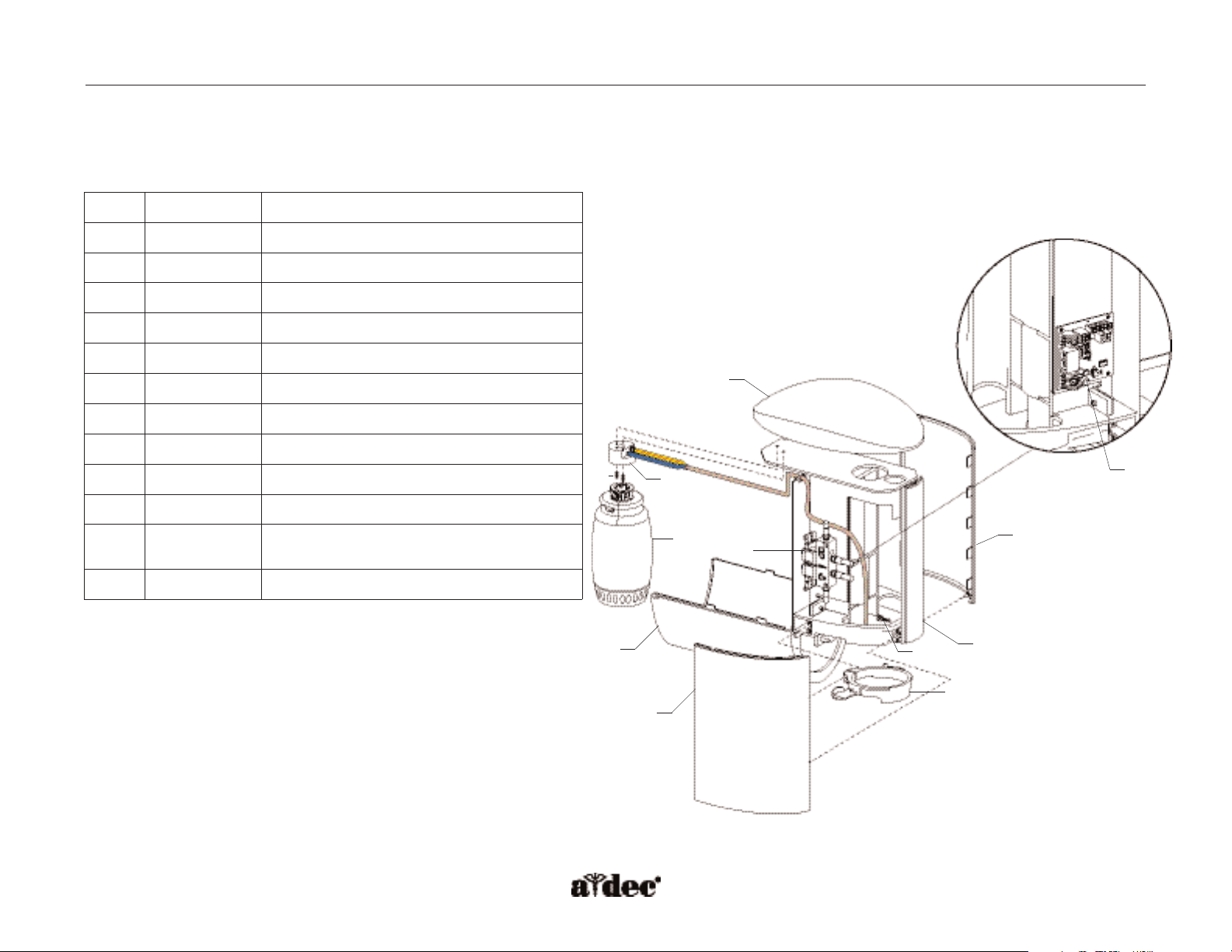
How to Identify Support Center Components
The support center houses the cuspidor fill/rinse manifold, cuspidor circuit board, and support side water bottle.
Item #
Part Number
Description
1
77.0034.00
Cover, top
2
77.0036.00
Cover, right
3
77.0037.00
Cover, nose
4
77.0035.00
Cover, left
5
14.0456.00
Cover, water bottle
6
38.1803.00
Cuspidor manifold
7
001.089.00
Screw
8
90.1079.00
Cuspidor circuit board kit
9
77.0232.00
Rotational stop
10
14.0469.00 Bottle receptacle assembly
11
002.112.00 Screw
NOTE: Torque 13-17 inch lb
12
14.0468.00 Self-contained water bottle assembly
1
2
4
3
5
6
7
8
9
10
11
12
Figure 80. Identification of the support center components.
Page 3

85.0816.00 Rev A 2004-11 (PCA 04002.12) Page 113
A-dec Service Guide, Vol. II Support Center Covers
Support Center Top Housing Cover Replacement
If replacement of the support center top housing cover is necessary, remove the support center top housing cover using these steps.
Cuspidor Removal
1. Remove side covers and water bottle cover.
2. Remove the two screws from under cuspidor support.
3. Disconnect the cup fill and bowl rinse tubings from the cuspidor fill/rinse manifold.
4. Disconnect the three wire connections from cuspidor circuit board
5. Remove the cuspidor by lifting it up and laying it on its side.
Top Housing Cover Removal
1. Remove the three screws from the top of cuspidor arm and lift off.
2. Remove the screw in the center of swivel and lift off the lower arm.
3. Remove the four screws holding the top cover on the housing, and lift off the top cover.
Top Housing Cover Replacement
Align two screws through lower arm and carefully thread into air trap bracket. Check seam alignment for bowl and arm, and tighten.
Page 4
Page 114 85.0816.00 Rev A 2004-11 (PCA 04002.12)
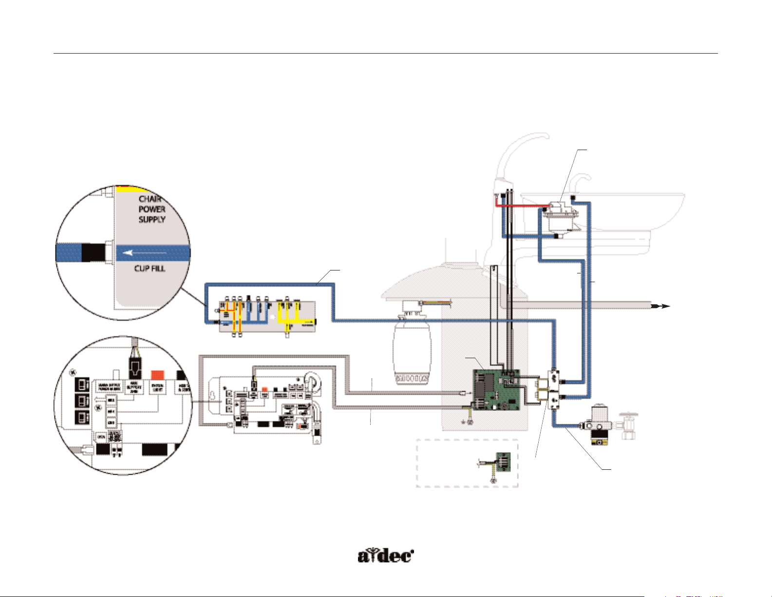
Cuspidor and Support Center Flow Diagram
This flow diagram describes the plumbing and electrical connections of the cuspidor and support center.
Flow Diagram A-dec Service Guide, Vol. II
Cuspidor
Support
center
Without
a cuspidor
Chair air/water manifold
Chair 300-watt
power supply
Water regulator for cuspidor only
(floor box)
Bowl rinse,
city water
Cup fill, self
contained
water
Cuspidor
circuit
board
Data line
Po wer cable
To gravity
drain (floor box)
Air trap valve assembly
Cuspidor
fill/rinse
manifold
Cup fill
City water
Page 5
85.0816.00 Rev A 2004-11 (PCA 04002.12) Page 115
A-dec Service Guide, Vol. II Cuspidor Circuit Board
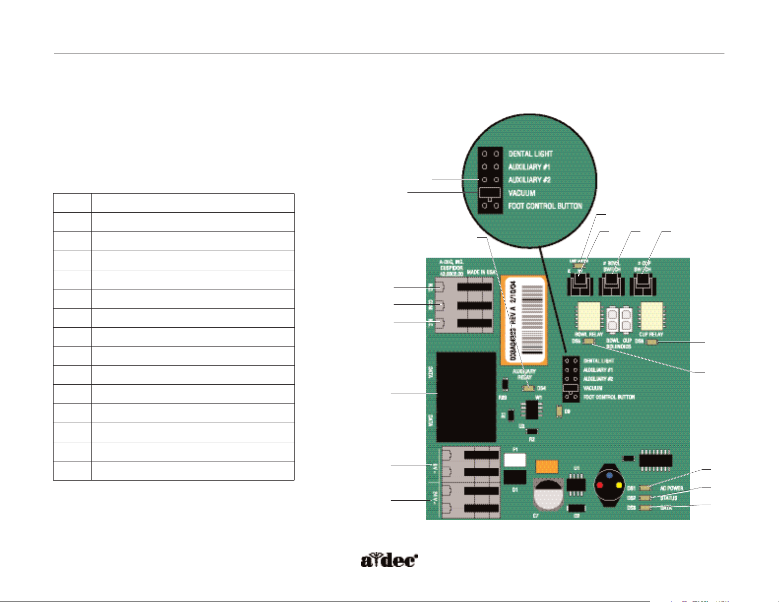
How to Identify Cuspidor Circuit Board Components
(P/N 90.1079.00)
The cuspidor circuit board controls the bowl rinse and cup fill solenoids.
The LEDs on the circuit board indicate the status of the cuspidor and can
be used for troubleshooting. The circuit board is also equipped with a
built-in A-dec relay.The built-in relay functions exactly like the A-dec
relay module.
Relay outputs
Item # Description
1
P5 - DCS terminals
2
J1 - Ø VAC terminal strip
3
J2 - 24 VAC terminal strip
4
P4 - Cuspidor limit switch connector
5
P2 - Bowl rinse switch connector
6
P3 - Cup fill switch connector
7
P1 - A-dec relay selection header
8
DS5 - Bowl rinse relay LED
9
DS6 - Cup fill relay LED
10
DS4 - Auxiliary relay LED
11
DS1 - AC power LED
12
DS2 - Status LED
13
DS3 - Data LED
14
DS7 - Limit switch LED
Figure 81. Cuspidor circuit board components.
N.O.
COM
N.C.
1
2
3
10
14
4
5 6
9
8
11
12
13
7
Relay jumper
Page 6
Page 116 85.0816.00 Rev A 2004-11 (PCA 04002.12)
Illustrated Parts A-dec Service Guide, Vol. II
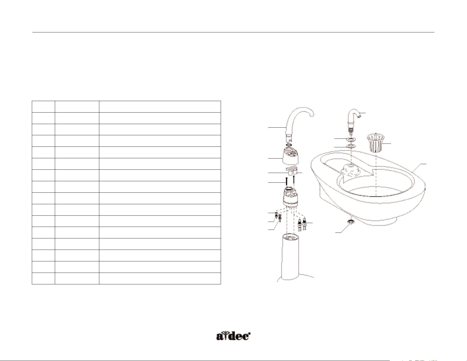
How to Identify Cuspidor Components
Upper Assembly
The cuspidor is preset with an automatic timed cup fill and bowl rinse. Both the cup fill and the bowl rinse functions can be reprogrammed.
Item #
Part Number
Description
1
77.0043.01
Cup fill spout
2
77.0042.01
Bowl rinse spout
3
77.0044.00
Spout gasket
4
77.0099.00
Bowl rinse button
5
77.0100.00
Cup fill button
6
005.088.00
Screw
7
77.0038.00
Cuspidor bowl
8
75.0035.01
Bowl screen, pkg 5
9
004.005.02
Washer, pkg 10
10
023.811.00 Barb
11
023.805.01 Barb, pkg 10
12
43.0010.00 Bowl rinse and cup fill switch assemblies
13
006.009.00 Nut
14
004.132.00 Washer
15
004.035.00 Washer
1
3
4
6
9
10
11
12
5
2
14
15
8
7
13
Figure 82. Identification of the upper cuspidor components.
Page 7
85.0816.00 Rev A 2004-11 (PCA 04002.12) Page 117
A-dec Service Guide, Vol. II Illustrated Parts
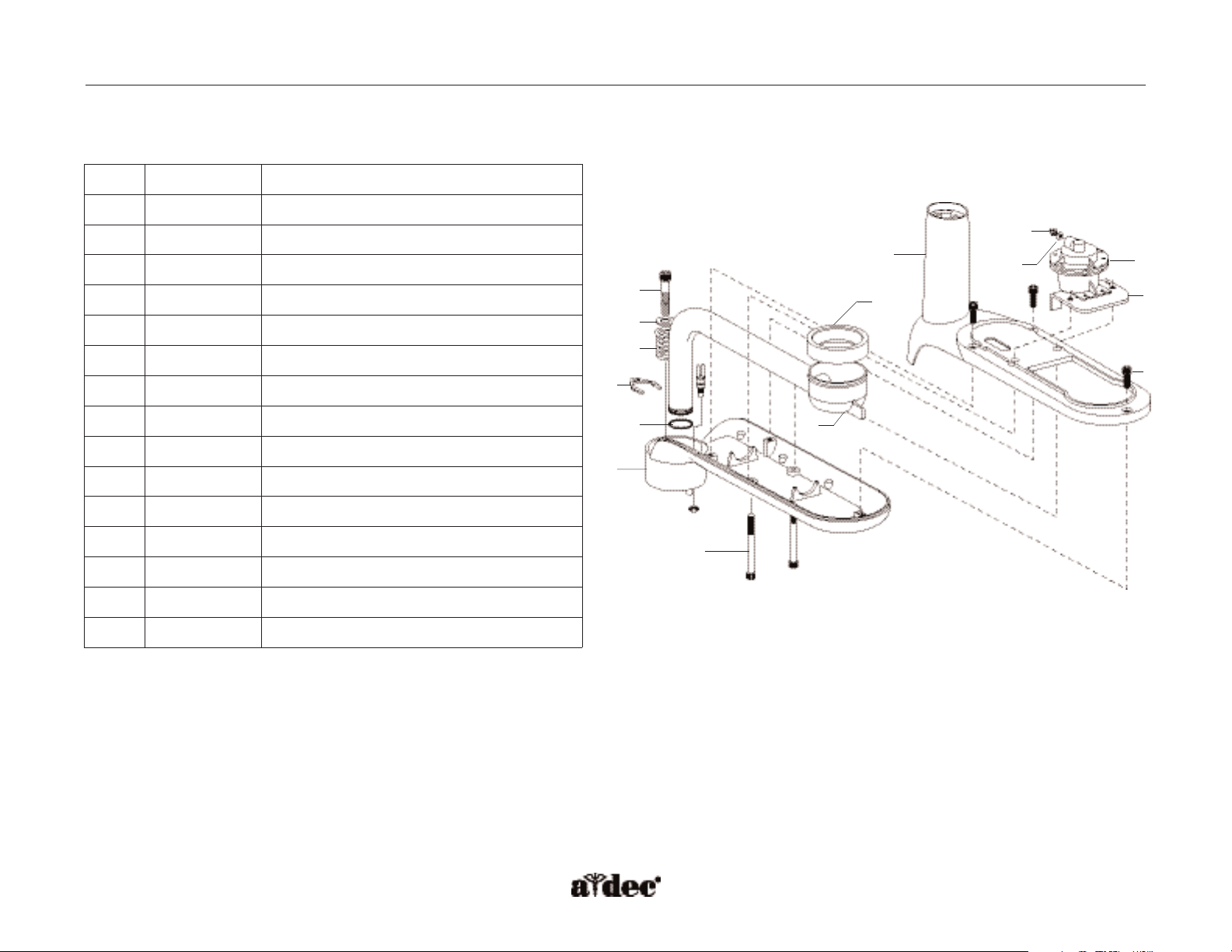
Lower Assembly
Item #
Part Number
Description
1
13.0403.00
Air trap valve assy
2
77.0236.00
Bracket, hold down
3
001.088.00
Screw
4
77.0108.00
Top housing
5
12.0991.00
Drain seal
6
002.082.03
Screw
7
004.141.00
Washer
8
013.061.01
Spring
9
77.0040.00
Cuspidor drain
10
022.090.00 Durr connector clip
11
035.053.01 O-ring, pkg 10
12
77.0109.00 Bottom housing
13
005.106.00 Screw
14
023.811.00 Restrictor barb
15
004.005.02 Washer, pkg 10
1
2
3
14
15
4
5
9
6
7
8
10
11
12
13
Figure 83. Identification of the lower cuspidor components.
Page 8
Page 118 85.0816.00 Rev A 2004-11 (PCA 04002.12)
Illustrated Parts A-dec Service Guide, Vol. II
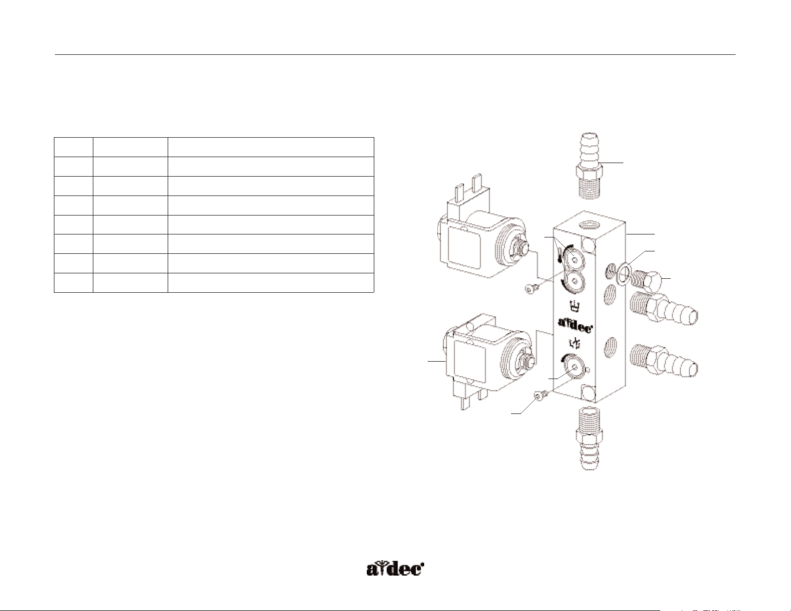
Cuspidor Fill/Rinse Manifold
(P/N 38.1803.00)
The cuspidor fill/rinse manifold assembly is mounted inside the support center.
Item #
Part Number
Description
1
041.660.00
Solenoid, 24 VAC
2
023.804.00
Barb, 5/16"
3
38.1794.00
Block, fill/rinse/mix
4
75.0222.00
Stem, flow adjustment
5
002.105.00
Screw, button head socket
6
004.005.02
Washer, pkg 10
7
021.016.04
Plug, hex head, pkg 10
2
3
6
7
5
4
1
4
Figure 84. Identification of the fill/rinse components.
Page 9

85.0816.00 Rev A 2004-11 (PCA 04002.12) Page 119
A-dec Service Guide, Vol. II Cuspidor Adjustments
How to Adjust the Cuspidor Timing
Cup Fill and Bowl Rinse Functions
Cup fill and bowl rinse timing can be reprogrammed using a touchpad or the footswitch program button and the appropriate button on the
cuspidor tower.
The cup fill function allows water to flow from the cuspidor cup fill spout into a cup. Quickly press the Cup Fill button to activate a timed
operation. A long press activates a manual operation.
The cup fill will only run a maximum of two minutes in the manual operation mode.
The bowl rinse function provides rinse water for the cuspidor bowl. A quick press of the bowl rinse button activates a timed operation. A long
press activates the manual operation. If the button is pressed twice in less than two seconds, the continuous operation will be activated. To stop
the continuous bowl rinse operation, press the bowl rinse button once.There is no maximum time limit for this function.
Figure 85. Cuspidor buttons for cup fill
and bowl rinse. (A) cup fill; (B) bowl rinse
A
B
Page 10

Page 120 85.0816.00 Rev A 2004-11 (PCA 04002.12)
Cuspidor Troubleshooting A-dec Service Guide, Vol. II
How to Troubleshoot the Cuspidor
Tips and troubleshooting information are listed in the tables to assist in diagnosing cuspidor problems.
These tables are not intended to cover every situation, but do include the most common problems that
may be encountered.
LED Status Function
DS1 - AC Power LED Off No 24 VAC power, tripped circuit breaker, power supply turned Off, no
line voltage
Green, steady 24 VAC at terminal strip
DS2 - Status LED Off System is not functioning, no power or circuit board has failed
Green, steady Normal condition
DS3 - Data LED Off No DCS communication, not connected to the data communication system, the
DCS has failed
Green, steady Active DCS detected
Green, blinking Valid DCS message
DS4 - Auxiliary relay LED Off Auxiliary relay is off
Yellow Auxiliary relay is on
DS5, DS6 - Bowl rinse/cup fill relays Off Relay is off
Yellow Relay is on
DS7 - Cuspidor limit switch LED Off Limit switch is not activated (closed)
Red Limit switch is activated (open)
Page 11

85.0816.00 Rev A 2004-11 (PCA 04002.12) Page 121
A-dec Service Guide, Vol. II Cuspidor Troubleshooting
Problem Possible Cause Action
Water drips from the cup fill spout The cup fill solenoid has failed or the solenoid
seat in the manifold has been damaged
Using the master On/Off toggle, turn the unit OFF. Use a syringe to bleed the
dental unit water pressure. Remove the cup fill solenoid. If the manifold seat
is good, replace the cup fill solenoid. If the manifold seat is damaged, replace
the manifold.
Water drips from the bowl rinse spout The bowl rinse solenoid has failed or the
solenoid seat in the manifold has been damaged
Close the manual city water shutoff. Use the master On/Off toggle to turn
the unit OFF and remove the bowl rinse solenoid. If the manifold seat is good,
replace the bowl rinse solenoid. If the manifold seat is damaged, replace
the manifold.
Cup fill and bowl rinse functions
are switched at the touchpad and
tower buttons
The cuspidor water solenoid connectors are
reversed on the cuspidor circuit board
Switch solenoid connections at P6 and P7.
Cup fill and bowl rinse functions are
switched at the tower buttons only
(touchpads operate normally)
The cuspidor tower switch connectors are
swapped on the cuspidor circuit board
Switch tower switch connections at P2 and P3.
Water runs constantly from either the cup
fill or bowl rinse spout and the red LED
(DS7) is illuminated on the cuspidor
circuit board
The cuspidor stop switch connector is
swapped with one of the cuspidor tower
switch connectors
The red LED (DS7) on the cuspidor circuit board is illuminated. Disconnect
all three switch connectors from the cuspidor circuit board. One at a time,
connect each of the switch connectors to the cuspidor circuit board until the red
LED goes out. Then connect one of the remaining switch connectors to
connector P3 on the cuspidor circuit board, and the other switch connector to
P2.Verify that a cup fill cycle runs when requested from the cuspidor tower cup
fill button. If the bowl rinse runs, swap the two switch connections to the
cuspidor circuit board.
Cup fill and bowl rinse functions are
switched at the touchpad only (tower
buttons operate normally)
The cuspidor water solenoid connectors and the
cuspidor tower switch connectors are swapped.
Switch the solenoid connections at P6 and P7. Switch the tower switch
connections at P2 and P3.
Page 12

Page 122 85.0816.00 Rev A 2004-11 (PCA 04002.12)
Cuspidor Troubleshooting A-dec Service Guide, Vol. II
Problem Possible Cause Action
Cup fill spout sputters air/water The self-contained water bottle is empty or
near empty
Refill the bottle.
The bowl rinse function works, but the
cup fill spout sputters excessively, and
does not work from the cuspidor cup fill
button or the touchpad
The cuspidor air trap valve is faulty Remove and replace the air trap valve.
Cuspidor works but the red LED
(DS7) on the cuspidor circuit board
is illuminated
The cuspidor stop switch is activated or the
wiring is faulty
Remove any obstacles from under the cuspidor bowl. Disconnect the cuspidor
stop switch from P4 on the cuspidor circuit board; install the jumper from P1
on the cuspidor circuit board. If the red LED on the cuspidor circuit board goes
out, the cuspidor stop switch or wiring is faulty and must be replaced.
Bowl rinse button on the cuspidor tower
does not work, but the function does
work from the touchpad
Cuspidor tower bowl rinse button assembly is
faulty or is disconnected from the cuspidor
circuit board P2 connector
Visually inspect the cuspidor circuit board. Ensure that the cuspidor tower
switches are connected.
• P2 - Bowl rinse switch
• P3 - Cup fill switch
If the switches are connected, check the continuity of the bowl rinse switch
with an Ohm meter. With the bowl rinse switch held down (closed),it should
measure less than ten Ohms. If it measures “open”across the closed switch,
remove and replace the bowl rinse switch assembly (P/N 43.0010.00).
NOTE: Switching switch assemblies at P2 and P3 allows verification that the
switch assembly is defective.
Cup fill button on the cuspidor tower
does not work but the function does
work from the touchpad
Cuspidor tower cup fill button assembly is faulty
or is disconnected from the cuspidor circuit
board P3 connector
Visually inspect the cuspidor circuit board, ensure that the cuspidor tower
switches are connected:
• P2 - Bowl Rinse Switch
• P3 - Cup Fill Switch
If the switches are connected, check the continuity of the cup fill switch with an
Ohm meter. With the cup fill switch held down (closed), it should measure less
than ten Ohms. If it measures “open”across the closed switch, remove and
replace the cup fill switch assembly (P/N 43.0010.00).
NOTE: Switching switch assemblies at P2 and P3 allows verification that the
switch assembly is defective.
Page 13

85.0816.00 Rev A 2004-11 (PCA 04002.12) Page 123
A-dec Service Guide, Vol. II Cuspidor Troubleshooting
Problem Possible Cause Action
Inadequate or excessive cup fill
water flow
The cup fill water flow needs adjustment Open the cup fill flow controls for full water flow. Turn the flow controls to
adjust the water flow.
The self-contained water system 40 psi regulator
has failed
The 40 psi regulator can be tested as follows:
1. Turn the dental unit OFF using the master On/Off toggle.
2. Remove the water bottle from the dental unit and set it aside.
3. Remove the air bleed setscrew from the water bottle cap assembly and set
it aside.
4. Install an 1/8" barb with washer in the port where the air bleed setscrew
was removed.
5. Connect an air pressure gauge to the 1/8" barb using the 1/8" tubing.
6. Turn the dental unit ON. The air pressure reading on the gauge should be
35 – 40 psi.
7. Turn the dental unit OFF using the master On/Off toggle.
8. Remove the air pressure gauge from the 1/8" barb and washer from the air
bleed setscrew port.
9. Reinstall the air bleed setscrew and replace the water bottle (continued on
next page).
Figure 86. Line up the indicator dots on
the flow controls to adjust.
Page 14

Page 124 85.0816.00 Rev A 2004-11 (PCA 04002.12)
Cuspidor Troubleshooting A-dec Service Guide, Vol. II
Problem Possible Cause Action
Inadequate or excessive cup fill
water flow (continued)
The self-contained water system 40 psi regulator
has failed
If a reading of 35 – 40 psi could not be obtained at the air bleed setscrew port,
the 40 psi regulator is faulty and must be replaced as follows:
1. Turn the dental unit OFF using the master On/Off toggle on the
delivery system.
2. Remove the water bottle cap assembly from the post or side support.
3. Remove and replace the 40 psi regulator.
4. Reinstall the water bottle cap assembly and water bottle.
5. Turn the dental unit ON and test the cup fill function for adequate
water pressure.
The self-contained water system air bleed set
screw is partially clogged with debris
1. Use the master On/Off toggle, to turn the dental unit OFF, and remove the
water bottle.
2. Remove the air bleed setscrew from the water bottle cap assembly and
clean it of debris, or replace it.
3. Reinstall the setscrew in the water bottle cap assembly and replace the
water bottle.
4. Turn the dental unit ON and test the cup fill function.
Inadequate bowl rinse water flow The bowl rinse water flow needs to be adjusted,
the water filter element is partially plugged, or
there is a kinked hose
Adjust the bowl rinse flow clockwise to increase water flow, or counterclockwise to
decrease flow, (one full turn from minimum to maximum).
To check for plugged water regulator filter element.
1. Close the city water manual shut-off valve in the floor box and bleed the
cuspidor bowl rinse water pressure, using the bowl rinse function.
2. Turn the dental unit OFF using the master On/Off toggle on the delivery
system and remove the water regulator filter element cap. Remove and
discard the filter element.
3. Install a new filter element on the water regulator and reinstall the filter cap.
4. Open the city water manual shut-off valve. Turn the dental unit ON using
the master On/Off toggle, and test the bowl rinse function for adequate
water flow.
Check for a restriction downstream from the filter. Locate and eliminate any kinks
in the blue 5/16" bowl rinse water tube.
Page 15

85.0816.00 Rev A 2004-11 (PCA 04002.12) Page 125
A-dec Service Guide, Vol. II Cuspidor Troubleshooting
Problem Possible Cause Action
Bowl rinse function does not work from
the cuspidor tower and/or the touchpad
bowl rinse button. The cup fill function
does work
The bowl rinse relay on the cuspidor circuit
board has failed
At the cuspidor circuit board, swap the water solenoid connectors at P6 and P7.
Press the cup fill button on any touchpad or the cup fill switch on the cuspidor
tower, if the bowl rinse runs, remove and replace the cuspidor circuit board.
The cuspidor data line is damaged Ensure that the cuspidor tower switches are connected:
• P2 – Bowl rinse switch
• P3 – Cup fill switch
Disconnect the data line from the cuspidor and press the bowl rinse switch on
the cuspidor tower. If the bowl rinse runs; remove and replace the cuspidor
data line.
The bowl rinse solenoid has failed Remove and replace the bowl rinse water solenoid.
Cup fill function does not work from the
cuspidor tower and/or from any touchpad
cup fill button. The bowl rinse function
does work
The cup fill relay on the cuspidor circuit board
has failed
Swap the water solenoid connectors at P6 and P7, at the cuspidor circuit board.
Press Bowl Rinse on any touchpad or the bowl rinse switch on the cuspidor
tower. If the cup fill runs, remove and replace the cuspidor circuit board.
The cuspidor data line is damaged Ensure that the cuspidor tower switches are connected correctly:
• P2 – Bowl rinse switch
• P3 – Cup fill switch
Disconnect the data line from the cuspidor and press the cup fill switch on the
cuspidor tower. If the cup fill runs; remove and replace the cuspidor data line.
The cup fill water solenoid has failed Remove and replace the cup fill water solenoid.
Page 16

Page 126 85.0816.00 Rev A 2004-11 (PCA 04002.12)
Support Side Water Bottle A-dec Service Guide, Vol. II
How to Identify Support Side Water Bottle Components
The self-contained water bottle mounts inside the support center module. To access the water
bottle, swing open the end cover of the support center. The support side water bottle uses the
same cap housing assembly to mount the water bottle as the front mount self-contained water
bottle, but without the outer housing.
CAUTION: Use caution when using the self-contained water system with any dental units
equipped with components that might fail when the water supply is interrupted.
Some types of scalers and water heaters are examples of components that can
be permanently damaged if operated without a continuous water source.
A-dec does not recommend using saline solutions, mouth rinses, or any
chemical solutions, not specified by A-dec, in the A-dec self-contained water
system. These may damage the water system components and cause the
failure of the dental unit.
How the Self-Contained Water Bottle Works
The A-dec self-contained water bottle uses air pressure to force water from the bottle into the
water pick-up tube and out to the chair air/water manifold. There it connects to various water
outputs such as the handpiece control block, syringe, and the cuspidor cup fill.
Figure 87. Swing open the end cover to
access the water bottle.
Figure 88. How the water bottle works.
Page 17

85.0816.00 Rev A 2004-11 (PCA 04002.12) Page 127
A-dec Service Guide, Vol. II Support Side Water Bottle Components
Support Side Water Bottle
The one-piece design of the A-dec water bottle reduces contamination when maintaining the system by not touching the pick-up tube during
refilling and maintenance.
WARNING: Use only A-dec water bottles. Do not use other brands, or damaged bottles.
They can pose a serious safety hazard if broken while pressurized.The A-dec plastic
water bottles cannot withstand heat sterilization. Attempting to do so will damage
the bottle and the sterilizer.
Item #
Part Number
Description
1
035.048.01
O-ring, pkg 10
2
14.0457.00
Connector
3
14.0453.00
Funnel
4
010.002.00
Retaining ring
5
031.130.01
O-ring, pkg 10
6
14.0458.00
Clamp
7
005.110.00
Screw
8
14.0466.00
Water bottle
1
2
3
4
5
8
6
7
Figure 89. Identification of the water bottle components.
Page 18

Page 128 85.0816.00 Rev A 2004-11 (PCA 04002.12)
How to Identify Amalgam Separator Housing Components
The A-dec 500 amalgam separator housing is attached to the support center. Use the support center nose cover on the amalgam separator
housing after installation.
Several brands of amalgam separators can be mounted inside the A-dec 500 amalgam separator housing. Follow the manufacturers instructions
for the specific separator being installed.
Item #
Part Number
Description
1
77.0011.00
Cover, top
2
77.0009.00
Cover, side (both sides)
3
77.0037.00 Cover, nose
2
1
3
Figure 90. Identification of the amalgam separator housing components.
Amalgam Separator Housing A-dec Service Guide, Vol. II
Page 19

85.0816.00 Rev A 2004-11 (PCA 04002.12) Page 129
A-dec Service Guide, Vol. II Amalgam Separator Housing
Item #
Part Number
Description
1
002.073.00
Sockethead screw 10-32 x 3/4
2
001.089.00
Sockethead screw 1/4-20 x 5/8
1
2
Figure 91. Identification of the amalgam separator housing mounting hardware.
Page 20

Page 130 85.0816.00 Rev A 2004-11 (PCA 04002.12)
Support Side Monitor Mount A-dec Service Guide, Vol. II
How to Identify Support Side Monitor Mount Components
Minimum Monitor Specifications:
Digital Monitor Requirements
• Medical-grade monitor
• 15" diagonal active display
• 1024 x 768 resolution
• Digital inputs
• VESA mounting compliant
•SVGA
Analog Monitor Requirements
• Color palette adjustments
• 13" HDTV flat panel for analog integration
• NTSC or PAL format
•Video inputs
• Composite video display capability
•RCA connection port
Item #
Part Number
Description
1
28.1501.00
Cap
2
001.088.00
Screw, adjustment
3
77.0213.00
Small cover, Surf 4
4
77.0026.00
Monitor mount cover
5
77.0102.00
Bearing, upper
6
77.0103.00
Bearing, lower
7
77.0201.00
Rotation stop
8
77.0112.00
Pivot assembly
9
77.0113.00*
VESA adapter
10
77.0199.00 Monitor post
11
*
Rigid arm
12
77.0114.01 Support arm
13
002.130.00 Button head screw
14
002.094.00 Screw
15
006.022.00 Nut
16
77.0115.00* Monitor bracket
17
77.0116.00* Monitor handle
* Item not for sale.
Page 21

85.0816.00 Rev A 2004-11 (PCA 04002.12) Page 131
A-dec Service Guide, Vol. II Support Side Monitor Mount
1
5
6
7
10
11
12
2
4
9
8
Power
supply
Monitor
Figure 92. Identification of the support side monitor mount components.
14
15
13
3
17
16
Page 22

Page 132 85.0816.00 Rev A 2004-11 (PCA 04002.12)
Support Side Monitor Mount A-dec Service Guide, Vol. II
Support Side Monitor Tray Holder
Item #
Part Number
Description
1
005.157.00
Screw
2
004.019.00
Washer
3
004.172.00
Washer
4
016.102.00
Thrust bearing
5
77.0365.00
Hub
6
004.242.00
Washer
7
77.0197.00
Extender
8
004.021.00
Washer
9
77.0189.00
Arm
10
77.0190.00 Bracket
11
77.0198.00 Cover
12
002.112.00 Screw
13
005.012.03 Screw
14
77.0071.00 Tray holder, large
15
75.0017.00 Standard tray holder
Page 23

85.0816.00 Rev A 2004-11 (PCA 04002.12) Page 133
A-dec Service Guide, Vol. II Support Side Monitor Mount
1
2
3
4
3
5
12
7
8
6
9
14
10
13
11
3
4
2
6
Figure 93. Identification of monitor tray holder components.
Page 24

Page 134 85.0816.00 Rev A 2004-11 (PCA 04002.12)
Support Side Monitor and Tray Holder Adjustments A-dec Service Guide, Vol. II
How to Adjust Support Side Mounted Monitor and Tray Holder
Monitor Mount Tilt/Friction Adjustments
There are two adjustments that can be made to the monitor: tilt and drift friction.
Tilt Friction
The tilt friction can be adjusted by tightening or loosening the tilt friction adjustment screw
located on the top of the monitor mount.
Drift Friction
The drift friction can be adjusted by tightening or loosening the drift adjustment screw located
on the top of the monitor mount.
Tray Holder Tension Adjustment
The tension adjustment screw for the tray holder is located in the hub of the tray holder arm.
1. Locate the small hole in the tray holder hub.
2. Insert a 5/32" hex key through the hole.
3. Rotate the tray support arm to adjust the tension, (clockwise
to increase tension — counterclockwise to decrease tension).
Figure 94. Monitor tilt and
friction adjustments.
Figure 95. Monitor tray adjustment.
 Loading...