


Adam Equipment
AE 503 INDICATOR
© Adam Equipment Company 2018

Easy Reference:
Model name of the indicator:
Serial number of the unit:
Software revision number
(Displayed when power is first turned on): Date of Purchase:
Name of the supplier and place:
© Adam Equipment Company 2018
© Adam Equipment Company 2018
CONTENTS
P.N. 7.00.6.6.0413, Revision A, September 2018
1.0 |
INTRODUCTION ....................................................................................................... |
3 |
|
2.0 |
SPECIFICATIONS..................................................................................................... |
4 |
|
3.0 |
INSTALLATION......................................................................................................... |
5 |
|
3.1 |
UNPACKING.......................................................................................................... |
5 |
|
3.2 |
LOCATING............................................................................................................. |
5 |
|
3.3 |
CONNECTION........................................................................................................ |
6 |
|
4.0 |
KEYPAD AND DISPLAY........................................................................................... |
7 |
|
4.1 |
KEYPAD................................................................................................................. |
7 |
|
4.2 |
DISPLAY................................................................................................................ |
8 |
|
5.0 |
BATTERY.................................................................................................................. |
9 |
|
5.1 |
BACKLIGHT........................................................................................................... |
9 |
|
5.2 |
SLEEP MODE........................................................................................................ |
9 |
|
6.0 |
OPERATION............................................................................................................ |
10 |
|
6.1 |
ZEROING ............................................................................................................. |
10 |
|
6.2 |
TARING................................................................................................................ |
10 |
|
6.2.1 |
MANUAL TARE .......................................................................................... |
10 |
|
6.3 |
WEIGHING........................................................................................................... |
11 |
|
6.4 |
PARTS COUNTING ............................................................................................. |
11 |
|
6.5 |
CHECK-WEIGHING ............................................................................................. |
13 |
|
6.5.1 |
SETTING UP CHECK WEIGHING PARAMETERS.................................... |
13 |
|
6.5.2 |
SETTING UP WHILE PARTS COUNTING OR % WEIGHING................... |
15 |
|
6.6 |
PERCENT WEIGHING......................................................................................... |
15 |
|
6.7 |
ANIMAL (DYNAMIC) WEIGHING ........................................................................ |
16 |
|
6.7.1 |
ANIMAL WEIGHING PROCEDURE ........................................................... |
17 |
|
6.8 |
ACCUMULATED TOTAL..................................................................................... |
18 |
|
6.8.1 |
ACCUMULATION PROCEDURE ............................................................... |
18 |
|
7.0 |
CALIBRATION ........................................................................................................ |
20 |
|
7.1 |
SIMPLE CALIBRATION....................................................................................... |
20 |
|
8.0 RS – 232 SPECIFICATION ..................................................................................... |
21 |
||
8.1 |
PRINT OUT DATA FORMAT............................................................................... |
22 |
|
8.1.1 |
CONTINUOUS MODE OUTPUT ................................................................ |
22 |
|
8.1.2 |
ANSWER MODE OUTPUT FROM PC ....................................................... |
22 |
|
9.0 |
LABEL PRINTING FUNCTION ............................................................................... |
23 |
|
9.1 |
LABEL EDITING COMPUTER SOFTWARE ....................................................... |
23 |
|
9.1.1 |
LABEL EDITOR SOFTWARE INTERFACE................................................ |
23 |
|
9.1.2 |
OPERATION METHOD .............................................................................. |
24 |
|
9.1.3 |
LABEL CUSTOMISATION.......................................................................... |
25 |
|
9.1.4 |
ADDING TEXT............................................................................................ |
25 |
|
9.1.5 |
ADDING PICTURES................................................................................... |
26 |
|
9.1.6 |
ADDING BARCODES................................................................................. |
27 |
|
9.1.7 |
ADDING QR CODES.................................................................................. |
28 |
|
9.1.8 |
DELETING ITEMS..................................................................................... |
28 |
|
9.2 |
LABEL DOWNLOAD PROCEDURE VIA RS 232 CABLE .................................. |
29 |
|
10.0 |
PARAMETER SETTINGS.................................................................................... |
29 |
|
10.1 |
UNIT PARAMETERS........................................................................................ |
30 |
|
10.2 |
COMMUNICATION PARAMETERS................................................................. |
31 |
|
10.3 |
FUNCTION PARAMETERS.............................................................................. |
33 |
|
11.0 |
ERROR MESSAGES ........................................................................................... |
36 |
|
12.0 |
SERVICE PARAMETERS.................................................................................... |
37 |
|
© Adam Equipment Company 2018 |
1 |
12.1 ACCESS TO THE SERVICE PARAMETERS................................................... |
37 |
12.1.1 FILTER SETTING (P4 FIL)......................................................................... |
37 |
12.1.2 CAPACITY AND DIVISION (P5 C-D).......................................................... |
38 |
12.1.3 MULTISTAGE CALIBRATION (P6 LI) ........................................................ |
39 |
12.1.4 CALIBRATION (P7 CALL) .......................................................................... |
39 |
12.1.5 CALIBRATION STORE AND RESTORE SETTING (P8 EC)...................... |
40 |
13.0 SERVICE INFORMATION.................................................................................... |
41 |
WARRANTY INFORMATION............................................................................................ |
42 |
© Adam Equipment Company 2018 |
2 |
1.0INTRODUCTION
The AE 503 from Adam Equipment is an accurate, fast and versatile general purpose weighing indicator with built in label printer that fulfills both weighing and data printing needs through a range of easy to operate functions including parts counting, percentage weighing and check-weighing.
The AE 503 provides clear and visible indication when a weight is below the low limit, between the limits or above the high limits using LCD symbols showing LO, OK and HI. These symbols can also work in conjunction with an audible alarm for check weighing.
Supplied with a RS-232 bi-directional interface and real time clock (RTC) allowing you to set parameters and keep data print outs organised.
The AE 503 has a sealed colour coded keypad and a large easy to read liquid crystal type display (LCD) supplied with a backlight.
Includes automatic zero tracking and accumulation facility that allows the weight to be stored and recalled as an accumulated total.
© Adam Equipment Company 2018 |
3 |

2.0SPECIFICATIONS
|
|
INPUT SECTION |
Load Cells |
|
Up to 8 , 350 ohm load cells |
Connection |
|
4 wire |
|
|
Auto compensation for long distance < 10 meters |
Excitation |
|
5Vdc |
Sensitivity |
|
0.02uv/e |
Zero Range |
|
Power on + - 20 % |
|
|
Manual + - 4% |
Signal range |
|
- 20mV - 20mV |
ADC Sensitivity |
|
0.01862uv/ADC (Maximum input voltage approximately 18.6 mV) |
DIGITAL SECTION |
|
Typically 1kg – 600000kg |
Maximum Range |
|
|
Divisions |
|
Up to 60,000 |
Weigh units |
|
kg / g / lb / oz / lb:oz / ct / dr / mm / T |
Stabilisation |
|
2 Seconds typical |
Time |
|
0°C - 40°C |
Operating |
|
|
Temperature |
|
32°F - 104°F |
Power supply |
|
12V 3 A |
Battery |
|
Internal rechargeable battery |
|
|
6V 10AH |
Calibration |
|
Automatic External |
Display |
|
6 digits LCD digital displays |
|
|
with symbols for units |
|
|
ABS Plastic |
Indicator |
|
|
Housing |
|
300 x 170 x 125mm |
Overall |
|
|
Dimensions |
|
|
(wxdxh) |
|
2.8 kg / 6 lb |
Net Weight |
|
|
|
|
Weighing and check weighing |
Applications |
|
|
|
|
Weighing, Check Weighing, Parts counting, check-counting, , Animal |
Functions |
|
|
|
|
Weighing, Accumulating memory, |
Interface |
|
RS-232 bi-directional interface |
|
|
English, German, French, Spanish and Italian |
|
|
|
© Adam Equipment Company 2018 |
4 |

3.0INSTALLATION
3.1UNPACKING
This indicator must be connected to a load cell platform and calibrated as necessary to match the platform and user requirements.
The user’s application and the technical specifications of the platform or load cell will determine the necessary configuration.
3.2 LOCATING
The indicator should not be placed in a location that will reduce the accuracy.
Avoid extremes of temperature. Do not place in direct sunlight or near air conditioning vents.
Avoid unsuitable tables. The table or floor must be rigid and not vibrate.
Avoid unstable power sources. Do not use near large users of electricity such as welding equipment or large motors.
Do not place near vibrating machinery.
Avoid high humidity that might cause condensation. Avoid direct contact with water. Do not spray or immerse the indicator in water.
Avoid air movement such as from fans or opening doors. Do not place near open windows or airconditioning vents.
Keep the indicator clean. Do not stack material on the indicator or platform when not in use.
© Adam Equipment Company 2018 |
5 |

3.3 CONNECTION
This indicator must be connected to a load cell platform and calibrated as necessary to match the platform and user requirements.
The AE 503 has a connector configured for a 4-wire load cell. Connect the load cells/platform to the indicator as shown below. The cable length should be as short as possible, using a large size wire to minimise errors due to resistance in the leads.
Figure 1B shows a preferred method to attach a 4 wire load cell, using a 6 conductor cable to go from the indicator to the platform or load cell where it connects to the 4 wires from the load cells. The Excitation and sense wires are connected together near the load cell.
For less exacting applications you can connect the excitation to the sense at the connector.
© Adam Equipment Company 2018 |
6 |

4.0KEYPAD AND DISPLAY
4.1KEYPAD
|
KEYS |
PRIMARY FUNCTION |
SECONDARY FUNCTION |
||
|
|
|
|
|
|
|
|
|
|
||
|
0 |
Sets the zero point for all subsequent |
Decrease displayed value |
||
|
weighing. The display shows zero. |
Exit from Menu |
|||
|
|
|
|
||
|
|
|
|
|
|
|
|
|
It tares the indicator and stores the |
Increase displayed value |
|
|
|
|
current weight in memory as a tare |
|
|
|
|
|
value, subtracts the tare value from the |
|
|
|
|
|
weight and shows the results. This is the |
|
|
|
|
|
net weight. |
|
|
|
|
|
|
|
|
|
|
|
This is used to select the weighing units |
To change parameter value in |
|
|
UNITS |
from a preset list of available units. |
menus |
||
|
|
|
|
To move to next digit in check |
|
|
|
|
|
weighing settings |
|
|
|
|
|
|
|
|
MODE |
It is used to print or output the results to |
Press and hold print key to enter |
||
|
a PC or printer using the RS-232 |
check weighing settings |
|||
|
|
|
interface. |
Select next menu item |
|
|
|||||
|
|
||||
|
|
|
Used for weight memory accumulation |
Press hold to get into setting |
|
|
M+ |
|
menu |
||
|
|
|
|||
|
|
|
|
|
|
|
MR |
Recall memory accumulation results |
Select next menu function |
||
|
|
|
|
|
|
© Adam Equipment Company 2018 |
7 |
4.2 DISPLAY
The LCD has unique symbols to indicate the following:
0 |
The display is at Zero |
|
The indicator platform is Stable |
Net |
Net weightThe scale has been tared |
Kg / Lb / g / ct /dr / oz / |
Symbols shown for the units |
lb:oz / mm / T / Ton |
|
LO-BAT or |
Low Battery |
|
The indicator is in Tare mode |
% |
The indicator is in Percent weighing mode |
PCS |
The indicator is in Parts counting mode |
|
The indicator is in Check weighing mode |
: |
The colons “:” are used to separate pounds from |
|
ounces and for the real time clock. |
value |
Indicator is in dynamic mode showing holding |
|
© Adam Equipment Company 2018 |
8 |
5.0BATTERY
The indicator can be operated from the rechargeable battery, if desired. The battery life is determined by the number and impendence of the load cells connected. With a single load cell and without use of the print function the battery life can last up to 150 hours before needing to be recharged.
When the battery needs charging the low battery symbol will appear on the top right of the LCD display indicating the battery needs charging. The indicator will still operate for a period of time before the display will show the flashing symbol ‘’LOBAT’’ meaning the indicator can no longer be used until recharged and will automatically switch off.
To charge the battery, simply plug into the mains power supply. The indicator does not need to be turned on. Once fully charged remove the mains power supply to help protect the battery.
The battery should be charged for 8 hours for full capacity.
To the right of the display is a LED to indicate the battery charging status. When the indicator is plugged into the mains power the internal battery will be charged. If the LED is red the indicator needs to be put on charge, the LED will continue to stay red until the battery is fully charged. When the indicator is fully charged the LED will turn green.
5.1 BACKLIGHT
The backlight for the LCD can be set by the user to always off, always on or automatic (on only when the indicator is in use or a key is pressed). See setting of the parameter “P3 FUN BL” in section 10.3.
5.2 SLEEP MODE
Sleep mode can be set by the user to disable the feature or to a pre-set time interval. See setting of the parameter “P3 FUN PWR” in section 10.3.
© Adam Equipment Company 2018 |
9 |

6.0OPERATION
6.1ZEROING
You can press the [Zero] key at any time to set the zero point from which all other weighing and counting is measured. This will usually be necessary when the platform is empty. When the zero point is obtained the display will show the zero indicator.
The indicator has an automatic re-zeroing function to account for minor drifting or accumulation of material on a connected platform. However, you may need to press
[Zero] to re-zero the indicator if small amount of weight is still shown when the platform is empty.
6.2TARING
6.2.1Manual tare
Zero the indicator by pressing [Zero]. The zero indicator will be on. Place a container on the pan and its weight will be displayed.
Press [Tare] when the reading is stable. The weight that was displayed is stored as the tare value and it is subtracted from the display, leaving zero on the display. The stable and Tare will be on.
As a product is added only the weight of the product will be shown. The indicator could be tared a second time if another type of product was to be added to the first one. Again, only the weight that is added after taring will be displayed.
NOTE:
When the container is removed a negative value will be shown. If the indicator was tared just before removing the container, this value is the gross weight of the
© Adam Equipment Company 2018 |
10 |

container plus all products which were removed. The zero indicator will also be on as the platform is back to the same condition it was when [Zero] was pressed last.
If the value to be tared is very large the scale may not allow you to tare the value as the negative value will not fit on the display area. In this case the scale will beep twice when the [Tare] key is pressed and then return to normal weighing without setting tare.
6.3 WEIGHING
To determine the weight of a sample, first tare an empty container if used, then place the sample in the container. The display will show the weight and the unit of weight currently in use.
To change the weighing unit, press the [Units] key. The various weighing unit options can be enabled by the user in the parameters section. See section 10.
6.4 PARTS COUNTING
The indicator can be used to count parts based on the average weight of a sample weighed. When more parts are added the total number of parts are displayed.
If a container is to be used, place this container on the platform before entering parts counting and press [Tare].
Ensure Parts Counting is enabled in the parameters section. See section 10.
To enter the Parts Counting mode, when in normal weighing mode press [Units] until ‘PCS’ is displayed. Check if the reading is “0”, if not, press [Zero] and the zero symbol will be displayed.
© Adam Equipment Company 2018 |
11 |
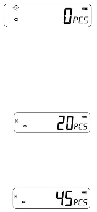
Put the desired sample on the weighing platform in order to determine its average weight. Once stable, press [Mode/Print], “N – XXX” will be displayed which stands for the sample quantity. For example, if 20 parts are placed on the platform then 20 would needed to be entered as the sample quantity. This is needed in order to determine the average piece weight.
Press [Units] to shift the flashing digit and use [Tare] to increase and [Zero] to decrease the value as necessary.
Press [MR] to weigh the samples and determine an average piece weight.
If the parts are too light to measure accurately, the count may become faulty. It is suggested that the samples to be weighed should each weigh more than the resolution of the indicator.
After the sample has been weighed the indicator will count any other parts added by applying the average piece weight to the weight of the parts to be counted.
The [Tare] key works normally during this time, so it is possible to tare the display with a container on the platform.
To count a different sample quantity press [Mode/Print]. The display will show the last used sample size. Either use this sample size with a different part or enter a new sample size as above.
Press [Units] to return back to normal weighing mode. If the sample is left on the platform the weight of the sample will be displayed.
© Adam Equipment Company 2018 |
12 |
 Loading...