


Aspire 4810T

Aspire 4810T/4810TZ/4410T/4810TG Series
Service Guide
Service guide files and updates are available
on the ACER/CSD web; for more information,
please refer to http://csd.acer.com.tw
PRINTED IN TAIWAN

Revision History
Please refer to the table below for the updates made on Aspire 4810T/4810TZ/4410T/4810TG Series service
guide.
Date Chapter Updates
II

Copyright
Copyright © 2009 by Acer Incorporated. All rights reserved. No part of this publication may be reproduced,
transmitted, transcribed, stored in a retrieval system, or translated into any language or computer language, in
any form or by any means, electronic, mechanical, magnetic, optical, chemical, manual or otherwise, without
the prior written permission of Acer Incorporated.
Disclaimer
The information in this guide is subject to change without notice.
Acer Incorporated makes no representations or warranties, either expressed or implied, with respect to the
contents hereof and specifically disclaims any warranties of merchantability or fitness for any particular
purpose. Any Acer Incorporated software described in this manual is sold or licensed "as is". Should the
programs prove defective following their purchase, the buyer (and not Acer Incorporated, its distributor, or its
dealer) assumes the entire cost of all necessary servicing, repair, and any incidental or consequential
damages resulting from any defect in the software.
Acer is a registered trademark of Acer Corporation.
Intel is a registered trademark of Intel Corporation.
Other brand and product names are trademarks and/or registered trademarks of their respective holders.
III

Conventions
The following conventions are used in this manual:
SCREEN MESSAGES Denotes actual messages that appear
on screen.
NOTE Gives bits and pieces of additional
information related to the current
topic.
WARNING Alerts you to any damage that might
result from doing or not doing specific
actions.
CAUTION Gives precautionary measures to
avoid possible hardware or software
problems.
IMPORTANT Reminds you to do specific actions
relevant to the accomplishment of
procedures.
IV

Preface
Before using this information and the product it supports, please read the following general information.
1. This Service Guide provides you with all technical information relating to the BASIC CONFIGURATION
decided for Acer's "global" product offering. To better fit local market requirements and enhance product
competitiveness, your regional office MAY have decided to extend the functionality of a machine (e.g.
add-on card, modem, or extra memory capability). These LOCALIZED FEATURES will NOT be covered
in this generic service guide. In such cases, please contact your regional offices or the responsible
personnel/channel to provide you with further technical details.
2. Please note WHEN ORDERING FRU PARTS, that you should check the most up-to-date information
available on your regional web or channel. If, for whatever reason, a part number change is made, it will
not be noted in the printed Service Guide. For ACER-AUTHORIZED SERVICE PROVIDERS, your Acer
office may have a DIFFERENT part number code to those given in the FRU list of this printed Service
Guide. You MUST use the list provided by your regional Acer office to order FRU parts for repair and
service of customer machines.
V

VI

Table of Contents
System Specifications 1
Features . . . . . . . . . . . . . . . . . . . . . . . . . . . . . . . . . . . . . . . . . . . . . . . . . . . . . . . . . . . .1
Aspire 4810T/4810TZ/4410T System Block Diagram . . . . . . . . . . . . . . . . . . . . . . . . .3
Aspire 4810TG System Block Diagram . . . . . . . . . . . . . . . . . . . . . . . . . . . . . . . . . . . .4
Your Acer Notebook tour . . . . . . . . . . . . . . . . . . . . . . . . . . . . . . . . . . . . . . . . . . . . . . .5
Right View . . . . . . . . . . . . . . . . . . . . . . . . . . . . . . . . . . . . . . . . . . . . . . . . . . . . . . .8
Indicators . . . . . . . . . . . . . . . . . . . . . . . . . . . . . . . . . . . . . . . . . . . . . . . . . . . . . .11
Easy-Launch Buttons . . . . . . . . . . . . . . . . . . . . . . . . . . . . . . . . . . . . . . . . . . . . .11
Touchpad basics (with two-click buttons) . . . . . . . . . . . . . . . . . . . . . . . . . . . . . .11
Using the Keyboard . . . . . . . . . . . . . . . . . . . . . . . . . . . . . . . . . . . . . . . . . . . . . . . . . .13
Lock Keys and Numeric Keypad . . . . . . . . . . . . . . . . . . . . . . . . . . . . . . . . . . . . .13
Windows Keys . . . . . . . . . . . . . . . . . . . . . . . . . . . . . . . . . . . . . . . . . . . . . . . . . . . . . .14
Hot Keys . . . . . . . . . . . . . . . . . . . . . . . . . . . . . . . . . . . . . . . . . . . . . . . . . . . . . . .15
Special Key (only for certain models) . . . . . . . . . . . . . . . . . . . . . . . . . . . . . . . . .15
Windows Mobility Center . . . . . . . . . . . . . . . . . . . . . . . . . . . . . . . . . . . . . . . . . .16
Using the System Utilities . . . . . . . . . . . . . . . . . . . . . . . . . . . . . . . . . . . . . . . . . . . . . .17
Acer GridVista (dual-display compatible) . . . . . . . . . . . . . . . . . . . . . . . . . . . . . .17
Hardware Specifications and Configurations . . . . . . . . . . . . . . . . . . . . . . . . . . . . . . .19
System Utilities 27
BIOS Setup Utility . . . . . . . . . . . . . . . . . . . . . . . . . . . . . . . . . . . . . . . . . . . . . . . . . . . .27
Navigating the BIOS Utility . . . . . . . . . . . . . . . . . . . . . . . . . . . . . . . . . . . . . . . . .28
Information . . . . . . . . . . . . . . . . . . . . . . . . . . . . . . . . . . . . . . . . . . . . . . . . . . . . .29
Main . . . . . . . . . . . . . . . . . . . . . . . . . . . . . . . . . . . . . . . . . . . . . . . . . . . . . . . . . .30
Security . . . . . . . . . . . . . . . . . . . . . . . . . . . . . . . . . . . . . . . . . . . . . . . . . . . . . . . .32
Boot . . . . . . . . . . . . . . . . . . . . . . . . . . . . . . . . . . . . . . . . . . . . . . . . . . . . . . . . . . .35
Exit . . . . . . . . . . . . . . . . . . . . . . . . . . . . . . . . . . . . . . . . . . . . . . . . . . . . . . . . . . .36
BIOS Flash Utility . . . . . . . . . . . . . . . . . . . . . . . . . . . . . . . . . . . . . . . . . . . . . . . . . . . .37
BIOS Flash Utility . . . . . . . . . . . . . . . . . . . . . . . . . . . . . . . . . . . . . . . . . . . . . . . . . . . .37
Remove HDD and BIOS Passwords . . . . . . . . . . . . . . . . . . . . . . . . . . . . . . . . . . . . .38
Machine Disassembly and Replacement 41
Disassembly Requirements . . . . . . . . . . . . . . . . . . . . . . . . . . . . . . . . . . . . . . . . . . . .41
General Information . . . . . . . . . . . . . . . . . . . . . . . . . . . . . . . . . . . . . . . . . . . . . . . . . .42
Pre-disassembly Instructions . . . . . . . . . . . . . . . . . . . . . . . . . . . . . . . . . . . . . . .42
Disassembly Process. . . . . . . . . . . . . . . . . . . . . . . . . . . . . . . . . . . . . . . . . . . . . 42
External Module Disassembly Process . . . . . . . . . . . . . . . . . . . . . . . . . . . . . . . . . . .43
Removing the Battery Pack . . . . . . . . . . . . . . . . . . . . . . . . . . . . . . . . . . . . . . . .44
Removing the Lower Cover . . . . . . . . . . . . . . . . . . . . . . . . . . . . . . . . . . . . . . . .45
Removing the Optical Drive Module . . . . . . . . . . . . . . . . . . . . . . . . . . . . . . . . . .46
Removing the DIMM . . . . . . . . . . . . . . . . . . . . . . . . . . . . . . . . . . . . . . . . . . . . . .46
Removing the Hard Disk Drive Module . . . . . . . . . . . . . . . . . . . . . . . . . . . . . . . .47
Removing the SSD Module . . . . . . . . . . . . . . . . . . . . . . . . . . . . . . . . . . . . . . .48
Removing the RTC Battery . . . . . . . . . . . . . . . . . . . . . . . . . . . . . . . . . . . . . . . . .48
Main Unit Disassembly Process . . . . . . . . . . . . . . . . . . . . . . . . . . . . . . . . . . . . . . . . .50
Removing the Keyboard . . . . . . . . . . . . . . . . . . . . . . . . . . . . . . . . . . . . . . . . . . .51
Removing the WLAN Board Module . . . . . . . . . . . . . . . . . . . . . . . . . . . . . . . . . .52
Separating the Upper Case from the Lower Case . . . . . . . . . . . . . . . . . . . . . . .53
Removing the Power Button Board . . . . . . . . . . . . . . . . . . . . . . . . . . . . . . . . . . .55
Removing the Touchpad Module . . . . . . . . . . . . . . . . . . . . . . . . . . . . . . . . . . . .56
Removing the Speaker Module . . . . . . . . . . . . . . . . . . . . . . . . . . . . . . . . . . . . . .57
Removing the LED Board . . . . . . . . . . . . . . . . . . . . . . . . . . . . . . . . . . . . . . . . . .58
Removing the LCD Module . . . . . . . . . . . . . . . . . . . . . . . . . . . . . . . . . . . . . . . . .59
Removing the System Board . . . . . . . . . . . . . . . . . . . . . . . . . . . . . . . . . . . . . . .61
VII

Table of Contents
Removing the Thermal Module . . . . . . . . . . . . . . . . . . . . . . . . . . . . . . . . . . . . . .63
Removing the Mini Board Module . . . . . . . . . . . . . . . . . . . . . . . . . . . . . . . . . . . .65
Removing the CRT Board Module . . . . . . . . . . . . . . . . . . . . . . . . . . . . . . . . . . .66
Removing the Card Reader Board . . . . . . . . . . . . . . . . . . . . . . . . . . . . . . . . . . .67
Removing the Bluetooth Module . . . . . . . . . . . . . . . . . . . . . . . . . . . . . . . . . . . . .68
Removing the Touchpad Lock Board . . . . . . . . . . . . . . . . . . . . . . . . . . . . . . . . .69
LCD Module Disassembly Process . . . . . . . . . . . . . . . . . . . . . . . . . . . . . . . . . . . . . .71
Removing the LCD Bezel . . . . . . . . . . . . . . . . . . . . . . . . . . . . . . . . . . . . . . . . . .72
Removing the LCD Panel Hinges . . . . . . . . . . . . . . . . . . . . . . . . . . . . . . . . . . . .73
Removing the LCD Panel . . . . . . . . . . . . . . . . . . . . . . . . . . . . . . . . . . . . . . . . . .74
Removing the Webcam . . . . . . . . . . . . . . . . . . . . . . . . . . . . . . . . . . . . . . . . . . . .76
Removing the Microphone . . . . . . . . . . . . . . . . . . . . . . . . . . . . . . . . . . . . . . . . .77
Troubleshooting 79
System Check Procedures . . . . . . . . . . . . . . . . . . . . . . . . . . . . . . . . . . . . . . . . . . . . .80
External Diskette Drive Check . . . . . . . . . . . . . . . . . . . . . . . . . . . . . . . . . . . . . .80
External Optical Disk Drive Check . . . . . . . . . . . . . . . . . . . . . . . . . . . . . . . . . . .80
Keyboard or Auxiliary Input Device Check . . . . . . . . . . . . . . . . . . . . . . . . . . . . .80
Memory Check . . . . . . . . . . . . . . . . . . . . . . . . . . . . . . . . . . . . . . . . . . . . . . . . . .81
Power System Check . . . . . . . . . . . . . . . . . . . . . . . . . . . . . . . . . . . . . . . . . . . . .81
Touchpad Check . . . . . . . . . . . . . . . . . . . . . . . . . . . . . . . . . . . . . . . . . . . . . . . . .82
Power-On Self-Test (POST) Error Messages . . . . . . . . . . . . . . . . . . . . . . . . . . . . . . .83
Post Code Table . . . . . . . . . . . . . . . . . . . . . . . . . . . . . . . . . . . . . . . . . . . . . . . . . . . . .84
Index of Symptom-to-FRU Errors . . . . . . . . . . . . . . . . . . . . . . . . . . . . . . . . . . . . . . . .87
Intermittent Problems . . . . . . . . . . . . . . . . . . . . . . . . . . . . . . . . . . . . . . . . . . . . . . . . .91
Undetermined Problems . . . . . . . . . . . . . . . . . . . . . . . . . . . . . . . . . . . . . . . . . . . . . . .92
Connector Locations 93
Top and Bottom Views . . . . . . . . . . . . . . . . . . . . . . . . . . . . . . . . . . . . . . . . . . . . . . . .93
Aspire 4810T/4810TZ/4410T Top View . . . . . . . . . . . . . . . . . . . . . . . . . . . . . . .93
Aspire 4810T/4810TZ/4410T Bottom View . . . . . . . . . . . . . . . . . . . . . . . . . . . . .94
Aspire 4810TG Top View . . . . . . . . . . . . . . . . . . . . . . . . . . . . . . . . . . . . . . . . . .95
Aspire 4810TG Bottom View . . . . . . . . . . . . . . . . . . . . . . . . . . . . . . . . . . . . . . . .96
Clearing Password Check and BIOS Recovery . . . . . . . . . . . . . . . . . . . . . . . . .97
BIOS Recovery by Crisis Disk . . . . . . . . . . . . . . . . . . . . . . . . . . . . . . . . . . . . . .98
FRU (Field Replaceable Unit) List 101
Aspire 4810T/4810TZ/4410T Series Exploded Diagram . . . . . . . . . . . . . . . . . . . . .102
Aspire 4810TG Series Exploded Diagram . . . . . . . . . . . . . . . . . . . . . . . . . . . . . . . .103
Aspire 4810T/4810TZ/4410T/4810TG Series . . . . . . . . . . . . . . . . . . . . . . . . . . . . . .119
Model Definition and Configuration 119
Test Compatible Components 133
Microsoft® Windows® Vista Environment Test . . . . . . . . . . . . . . . . . . . . . . . . . . . .134
Online Support Information 137
Index 139
VIII

System Specifications
Features
Below is a brief summary of the computer’s many feature:
Platform
• Intel
• Intel
• Intel
• Mobile Intel
®
Centrino® 2 mobile processor technology, featuring:
• Intel
• Intel
• Mobile Intel
• Intel
• Intel
• Acer InviLink
®
Core™2 Duo processor*
®
Core™2 Solo processor*
®
GS45 Express Chipset
®
Wireless WiFi Link 5100*
®
Wireless WiFi Link 5150*
®
Pentium® mobile processor*
®
Celeron® mobile processor*
®
GS45 Express Chipset
™
Nplify™ 802.11b/g/Draft-N*
Chapter 1
System Memory
• Dual-Channel SDRAM support
• Up to 2 GB of DDR3 1066 MHz memory, upgradeable to 4 GB using two soDIMM modules*
• Up to 4 GB of DDR3 1066 MHz memory, upgradeable to 8 GB using two soDIMM modules*
Display and graphics
• 16:9 aspect ratio
• 14" HD 1366 x 768
Storage subsystem
• 2.5" hard disk drive / solid state drive
• DVD-Super Multi double-layer drive
• 5-in-1 card reader
Special keys and controls
• 86-/87-/91-key keyboard
• Touchpad pointing device
Audio
• High-definition audio support
• S/PDIF (Sony/Philips Digital Interface) support for digital speakers
• MS-Sound compatible
• Built-in microphone
Chapter 1 1

Communication
• Integrated Acer Crystal Eye webcam
• Wi-Fi/WiMAX: Intel
• WWAN:
• UMTS/HSPA at 900 MHz/2100 MHz and quad-band GSM/GPRS/EDGE
®
Wireless WiFi Link 5150*
(850/900/1800/1900 MHz)*
• UMTS/HSPA at 850 MHz/900 MHz/1900 MHz/2100 MHz and quad-band GSM/GPRS/EDGE
(850/900/1800/1900 MHz)*
• WLAN:
• Intel
• Acer InviLink
• WPAN: Bluetooth
• LAN: Gigabit Ethernet; Wake-on-LAN ready
®
Wireless WiFi Link 5100*
™
Nplify™ 802.11b/g/Draft-N*
®
2.0+Enhanced Data Rate (EDR)*
I/O Ports
• 5-in-1 card reader (SD/MMC/MS/MS PRO/xD)
• USB 2.0 port
• HDMI
• External display (VGA) port
• Headphones/speaker/line-out jack with S/PDIF support
• Microphone-in jack
• Ethernet (RJ-45) port
• DC-in jack for AC adapter
™
port with HDCP support
Environment
• Temperature:
• Operating: 5 °C to 35 °C
• Non-operating: -20 °C to 65 °C
• Humidity (non-condensing):
• Operating: 20% to 80%
• Non-operating: 20% to 80%
NOTE: * Only for certain models.
NOTE: The specifications listed above are for reference only. The exact configuration of your PC depends on
the model purchased.
2 Chapter 1
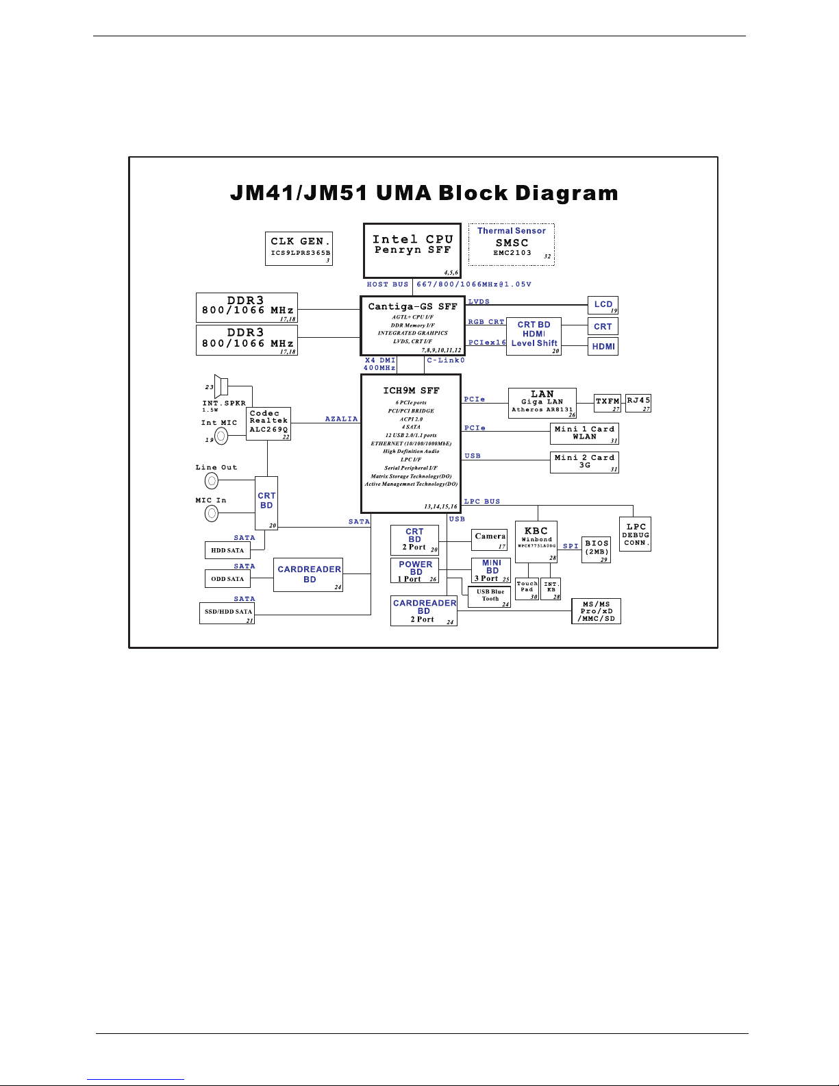
Aspire 4810T/4810TZ/4410T System Block Diagram
Chapter 1 3
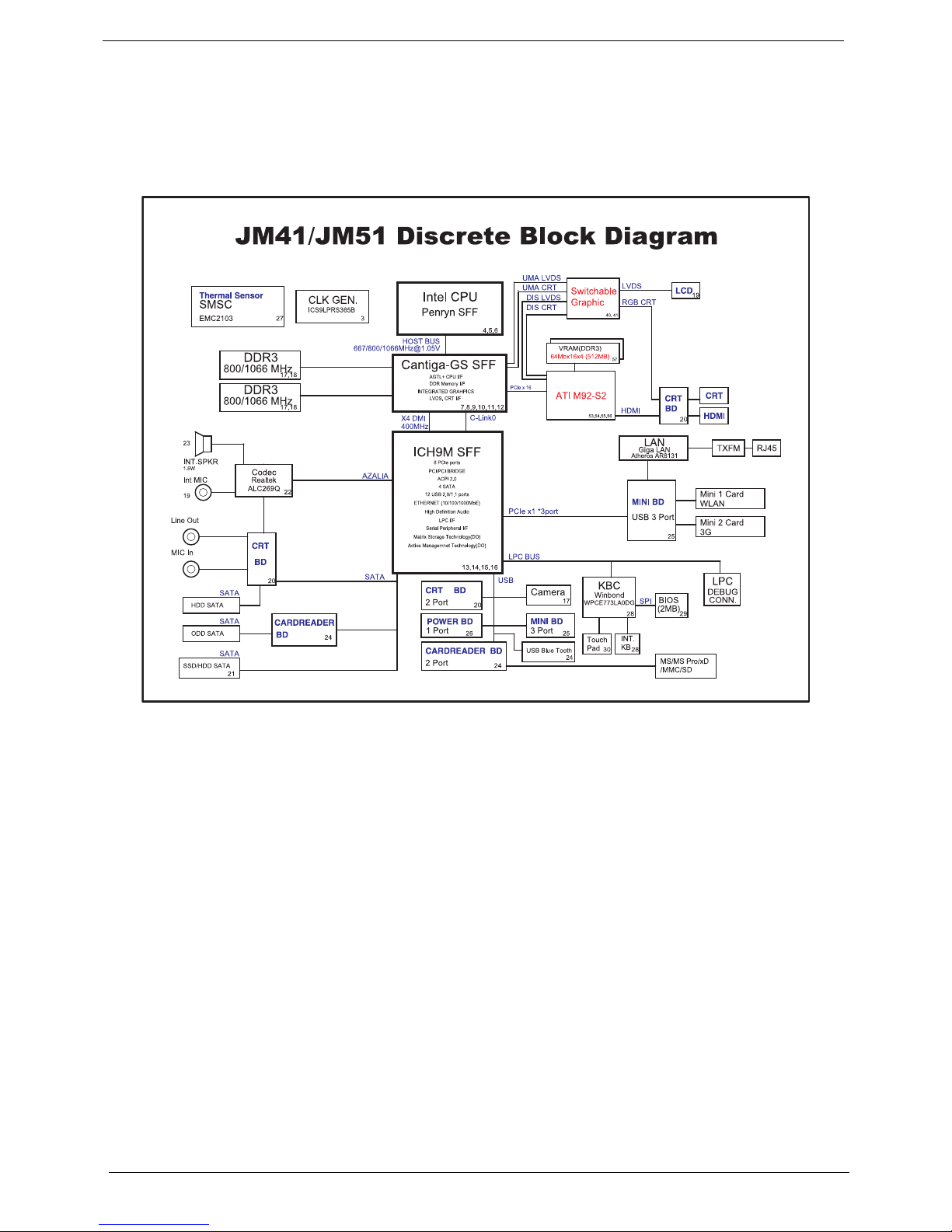
Aspire 4810TG System Block Diagram
4 Chapter 1
Your Acer Notebook tour
After knowing your computer features, let us show you around your new computer.
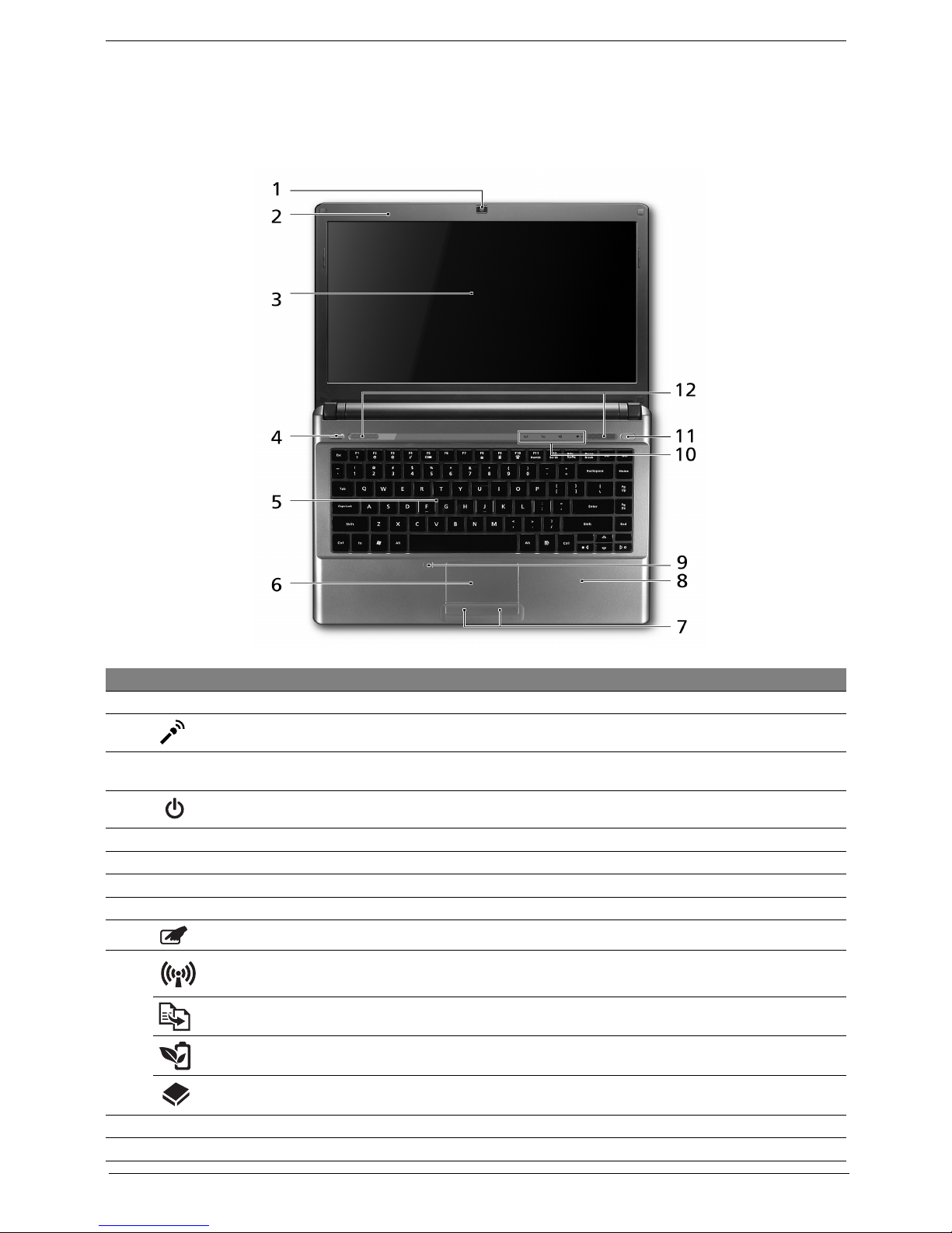
Top View
# Icon Item Description
1 Acer Crystal Eye webcam Web camera for video communication.
2 Microphone Internal microphone for sound recording.
3 Display screen Also called Liquid-Crystal Display (LCD), displays computer output
(Configuration may vary by models).
4 Power button / indicator Turns the computer on and off. / Indicates the computer's power status.
5 Keyboard For entering data into your computer.
6 Touchpad Touch-sensitive pointing device which functions like a computer mouse.
7 Click buttons (left and right) The left and right buttons function like the left and right mouse buttons.
8 Palmrest Comfortable support area for your hands when you use the computer.
9 Touchpad toggle Turns the internal touchpad on and off.
10 Communication key Enables / disables the WLAN / 3G functions.
Backup key Launches Acer Backup Management for three-step data backup.
Acer PowerSmart key Puts your computer into power-saving mode.
HDD Indicates when the hard disk drive is active.
11 Eject button Presses to eject the optical disk from the drive.
12 Speakers Left and right speakers deliver stereo audio output.
Chapter 1 5
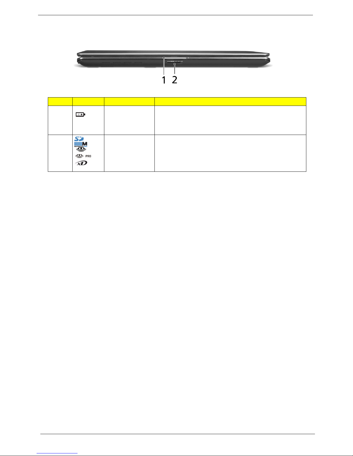
Closed Front View
Icon Item Description
1 Battery Indicates the computer's battery status.
2 5-in-1 card reader Accepts Secure Digital (SD), MultiMediaCard (MMC),
1. Charging: The light shows amber when the battery is
charging.
2. Fully charged: The light shows blue when in AC mode.
Memory Stick (MS), Memory Stick PRO (MS PRO), xDPicture Card (xD).
Note: Push to remove/install the card. Only one card can
operate at any given time.
6 Chapter 1
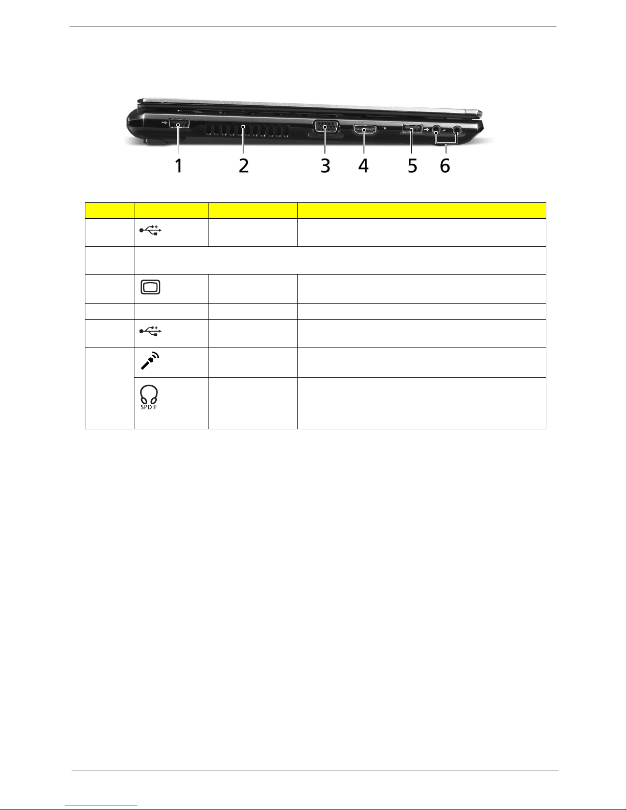
Left View
# Icon Item Description
1 USB 2.0 port Connect to USB 2.0 devices (e.g., USB mouse, USB
2 Ventilation slots Enable the computer to stay cool, even after prolonged
3 External display
4
5 USB 2.0 port Connect to USB 2.0 devices (e.g., USB mouse, USB
6
HDMI
camera).
use.
Connects to a display device (e.g., external monitor, LCD
(VGA) port
HDMI port Supports high definition digital video connections.
Microphone-in jack
projector).
camera).
Accepts inputs from external microphones.
Headphones/
speaker/line-out
jack with
S/PDIF support
Connects to audio line-out devices
(e.g., speakers, headphones).
Chapter 1 7
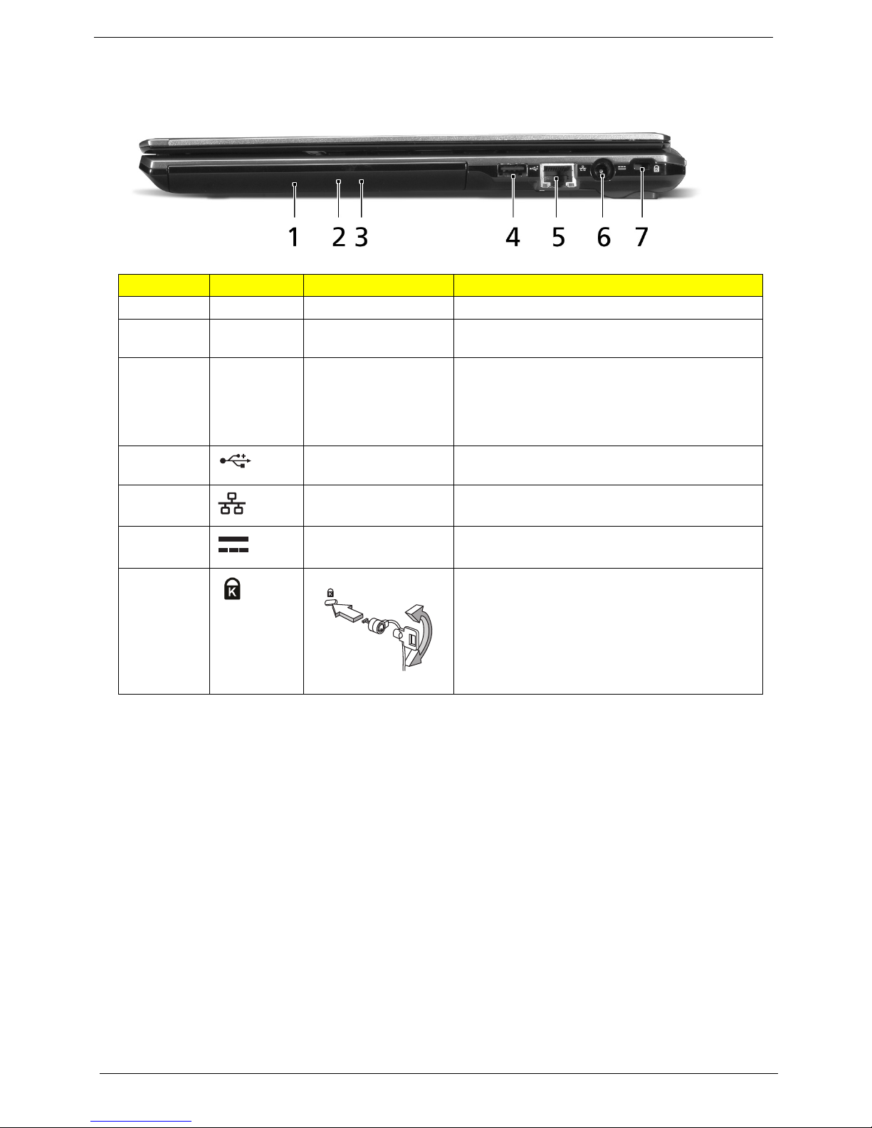
Right View
# Icon Item Description
1 Optical drive Internal optical drive; accepts CDs or DVDs.
2 Optical disk access
3 Emergency eject hole Ejects the optical drive tray when the computer is
4 USB 2.0 port Connects to USB 2.0 devices (e.g., USB mouse,
5 Ethernet (RJ-45) port Connects to an Ethernet 10/100/1000-based
Lights up when the optical drive is active.
indicator
turned off.
Note: Insert a paper clip to the emergency eject
hole to eject the optical drive tray when the
computer is off.
USB camera).
network.
6 DC-in jack Connects to an AC adapter.
7 Kensington lock slot Connects to a Kensington-compatible computer
security lock.
Note: Wrap the computer security lock cable
around an immovable object such as a table or
handle of a locked drawer. Insert the lock into the
notch and turn the key to secure the lock. Some
keyless models are also available.
8 Chapter 1
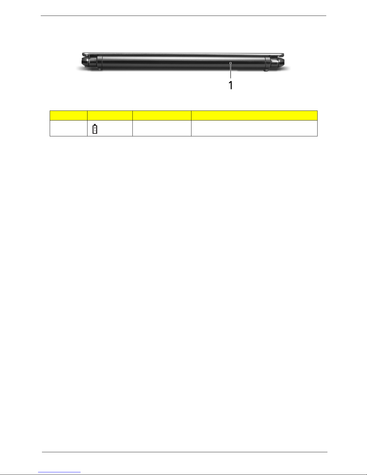
Rear View
# Icon Item Description
1 Battery bay Houses the computer's battery pack.
Chapter 1 9
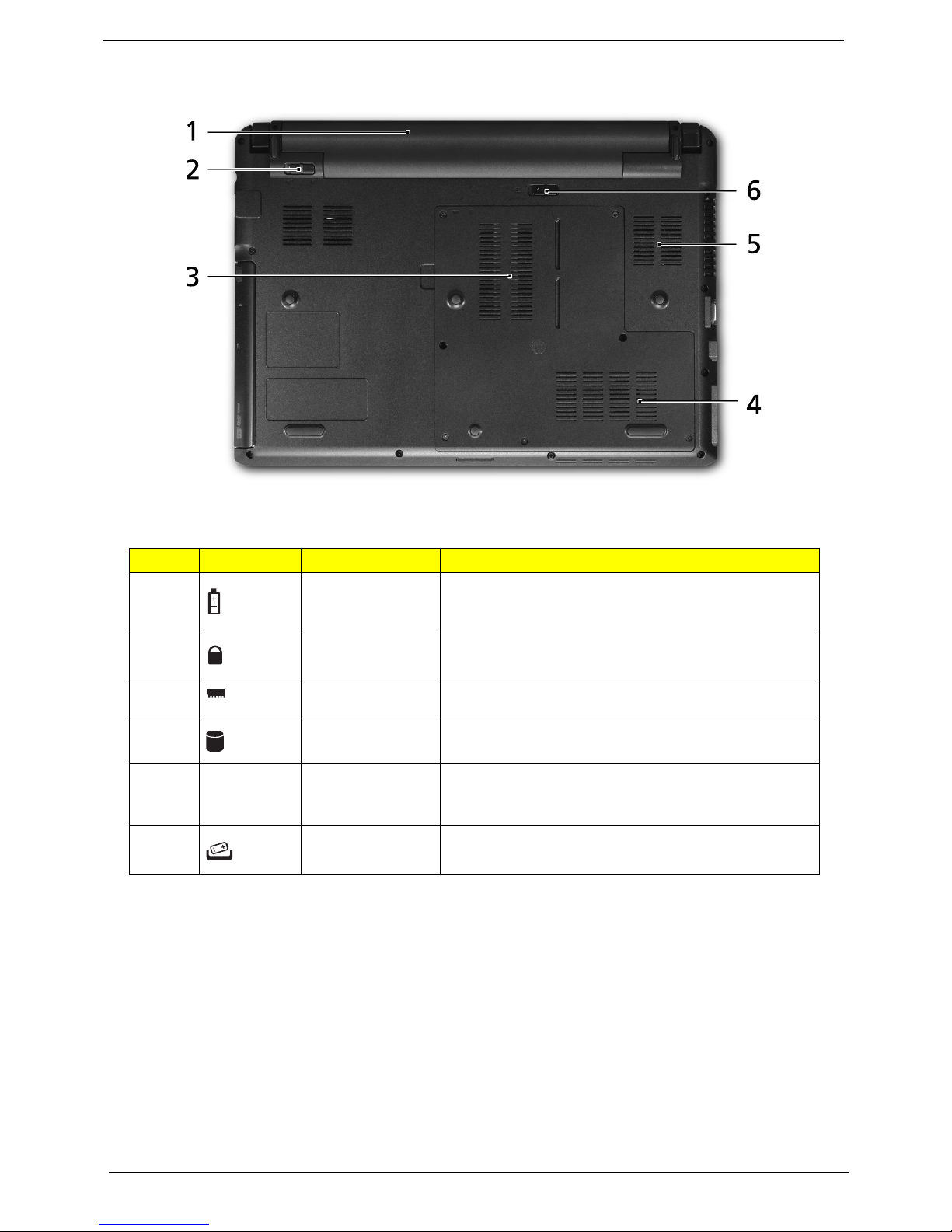
Bottom View
Icon Item Description
1 Battery bay Houses the computer's battery pack.
2 Battery lock Locks the battery in position.
3 Memory
compartment
4 Hard disk bay Houses the computer's hard disk
5 Ventilation slots
and cooling fan
6 Battery release
latch
Houses the computer's main memory.
(secured with screws).
Enable the computer to stay cool, even after prolonged
use.
Note: Do not cover or obstruct the opening of the fan.
Releases the battery for removal.
10 Chapter 1
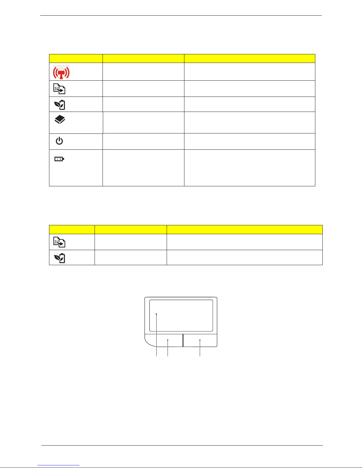
Indicators
The computer has several easy-to-read status indicators. The front panel indicators are visible even when the
computer cover is closed.
Icon Function Description
WLAN/3G (Manufacturing
option)
Backup key Launches Acer Backup Management for three-
Acer PowerSmart key Puts your computer into power-saving mode.
HDD Indicates when the hard disk drive is active.
Power button / indicator Turns the computer on and off. /
Battery Indicates the computer's battery status.
Indicates the status of WLAN/3Gcommunication.
step data backup.
Indicates the computer's power status.
1. Charging: The light shows amber when the
battery is charging.
2. Fully charged: The light shows blue when in
AC mode.
Easy-Launch Buttons
Located above the keyboard are application buttons. These buttons are called easy-launch buttons. They are:
Backup and Acer PowerSmart indicators/buttons.
Icon Function Description
Backup key Launches Acer Backup Management for three-step data
backup.
Acer PowerSmart key Puts your computer into power-saving mode.
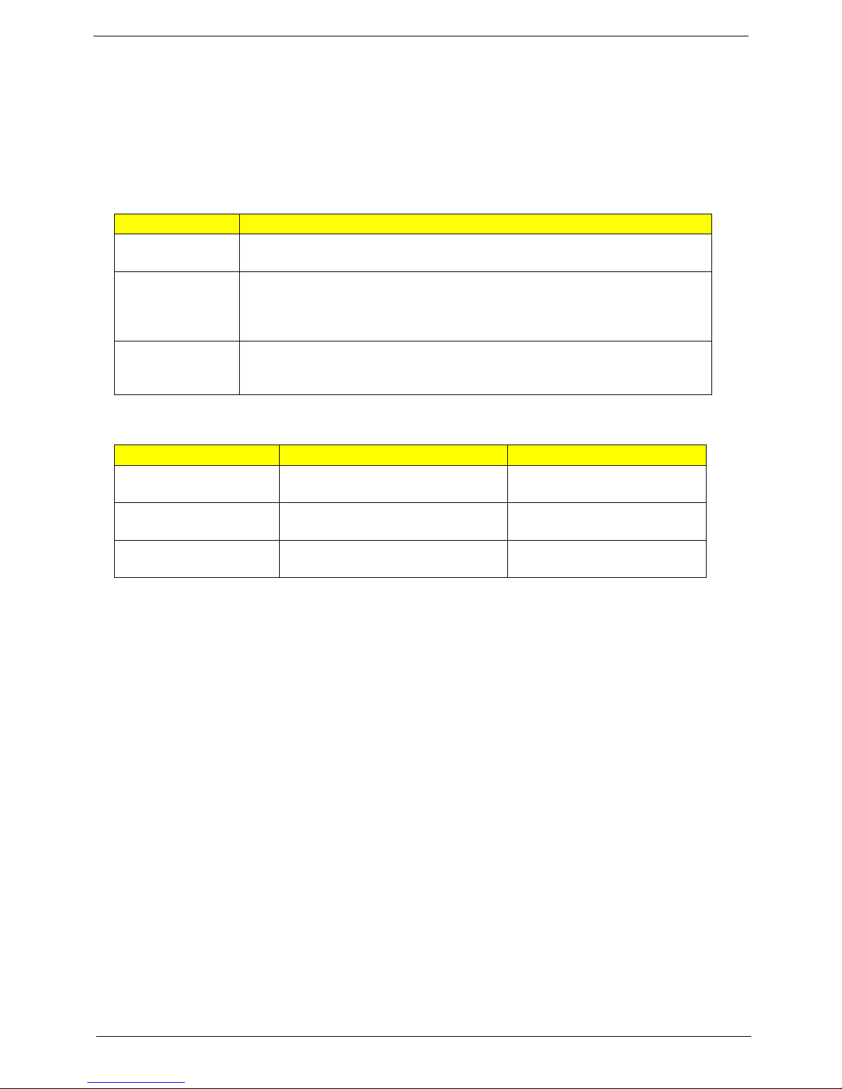
Touchpad basics (with two-click buttons)
The following items show you how to use the touchpad with two-click buttons.
1 23
• Move your finger across the touchpad (1) to move the cursor.
• Press the left (2) and right (3) buttons located beneath the touchpad to perform selection and execution
functions. These two buttons are similar to the left and right buttons on a mouse. Tapping on the
touchpad is the same as clicking the left button.
Chapter 1 11

Function Left button (2) Right button (3) Main touchpad (1)
Execute Quickly click twice. Tap twice (at the same speed as double-clicking
a mouse button).
Select Click once. Tap once.
Drag Click and hold, then use
finger on the touchpad
to drag the cursor.
Access
Click once.
Tap twice (at the same speed as double-clicking
a mouse button); rest your finger on the touchpad
on the second tap and drag the cursor.
context menu
NOTE: Illustrations for reference only. The exact configuration of your PC depends on the model purchased.
NOTE: When using the touchpad, keep it — and your fingers — dry and clean. The touchpad is sensitive to
finger movement; hence, the lighter the touch, the better the response. Tapping harder will not increase
the touchpad's responsiveness.
NOTE: By default, vertical and horizontal scrolling is enabled on your touchpad. It can be disabled under
Mouse settings in Windows Control Panel.
12 Chapter 1
Using the Keyboard
The keyboard has full-sized keys and an embedded numeric keypad, separate cursor, lock, Windows, function
and special keys.
Lock Keys and Numeric Keypad
The keyboard has three lock keys which you can toggle on and off.
Lock key Description
Caps Lock When Caps Lock is on, all alphabetic characters typed are
in uppercase.
Num Lock When Num Lock is on, the numeric keypad is in numeric mode. The keys
function as a calculator (complete with the arithmetic operators +, -, *, and /).
Use this mode when you need to do a lot of numeric data entry. A better solution
would be to connect an external keypad.
Scroll Lock <Fn> +
<F12>
The keyboard has a numeric keypad with cursor-control keys.
Desired access Num Lock on Num Lock off
Number keys on
embedded keypad
Cursor-control keys on
embedded keypad
Main keyboard keys Hold <Fn> while typing letters on
When Scroll Lock is on, the screen moves one line up or down when you press
the up or down arrow keys respectively. Scroll Lock does not work with some
applications.
Type numbers in a normal manner.
Hold <Shift> while using cursorcontrol keys.
embedded keypad.
Hold <Fn> while using cursorcontrol keys.
Type the letters in a normal
manner.
Chapter 1 13
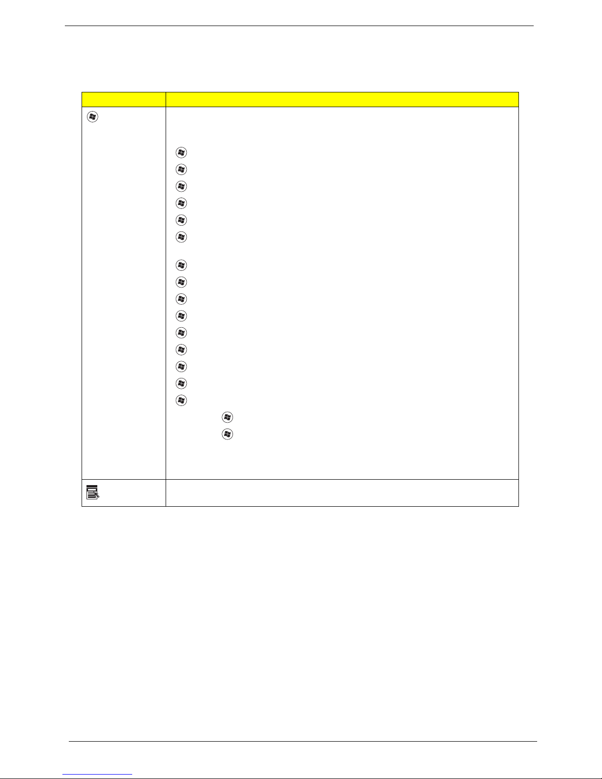
Windows Keys
The keyboard has two keys that perform Windows-specific functions.
Key Description
Windows
key
Pressed alone, this key has the same effect as clicking on the Windows Start button;
it launches the Start menu.
It can also be used with other keys to provide a variety of functions:
< >: Open or close the Start menu
< > + <D>: Display the desktop
< > + <E>: Open Windows Explore
< > + <F>: Search for a file or folder
< > + <G>: Cycle through Sidebar gadgets
< > + <L>: Lock your computer (if you are connected to a network domain), or
switch users (if you're not connected to a network domain)
< > + <M>: Minimizes all windows
< > + <R>: Open the Run dialog box
< > + <T>: Cycle through programs on the taskbar
< > + <U>: Open Ease of Access Center
< > + <X>: Open Windows Mobility Center
Application
key
< > + <BREAK>: Display the System Properties dialog box
< > + <SHIFT+M>: Restore minimized windows to the desktop
< > + <TAB>: Cycle through programs on the taskbar by using Windows Flip 3-D
< > + <SPACEBAR>: Bring all gadgets to the front and select Windows Sidebar
<CTRL> + < > + <F>: Search for computers (if you are on a network)
<CTRL> + < > + <TAB>: Use the arrow keys to cycle through programs on the
taskbar by using Windows Flip 3-D
Note: Depending on your edition of Windows Vista, some shortcuts may not function
as described.
This key has the same effect as clicking the right mouse button; it opens the
application's context menu.
14 Chapter 1
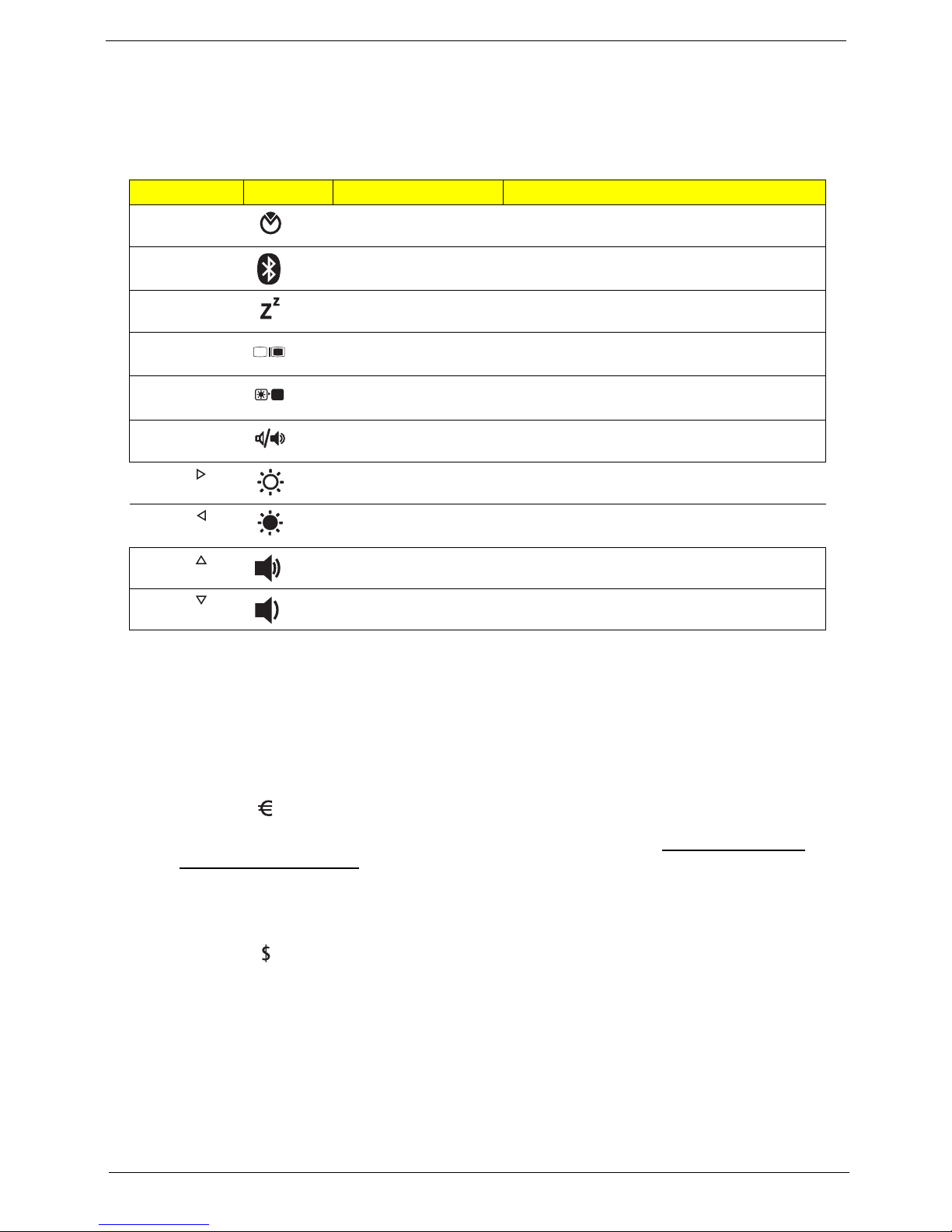
Hot Keys
The computer employs hotkeys or key combinations to access most of the computer’s controls like screen
brightness, volume output and the BIOS utility.
To activate hot keys, press and hold the <Fn> key before pressing the other key in the hotkey combination.
Hotkey Icon Function Description
<Fn> + <F2> System property Starts System Property for displaying system
information.
<Fn> + <F3> Bluetooth Enables/disables the Bluetooth function. (only
for certain models)
<Fn> + <F4> Sleep Puts the computer in Sleep mode.
<Fn> + <F5> Display toggle Switches display output between the display
screen, external monitor (if connected) and both.
<Fn> + <F6> Screen blank Turns the display screen backlight off to save
power. Press any key to return.
<Fn> + <F8> Speaker toggle Turns the speakers on and off.
<Fn> + < > Brightness up Increases the screen brightness.
<Fn> + < > Brightness down Decreases the screen brightness.
<Fn> + < > Volume up Increases the sound volume.
<Fn> + < > Volume down Decreases the sound volume.
Special Key (only for certain models)
You can locate the Euro symbol and the US dollar sign at the upper-center and/or bottom-right of your
keyboard.
The Euro symbol
1. Open a text editor or word processor.
2. Either press < > at the bottom-right of the keyboard, or hold <Alt Gr> and then press the <5> key at the
upper-center of the keyboard.
NOTE: Some fonts and software do not support the Euro symbol. Please refer to www.microsoft.com/
typography/faq/faq12.htm for more information.
The US dollar sign
1. Open a text editor or word processor.
2. Either press < > at the bottom-right of the keyboard, or hold <Shift> and then press the <4> key at the
upper-center of the keyboard.
NOTE: This function varies according to the language settings.
Chapter 1 15
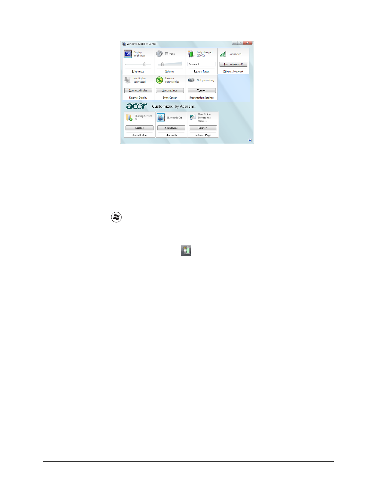
Windows Mobility Center
The Windows Mobility Center collects key mobile-related system settings in one easy-to-find place, so you can
quickly configure your Acer system to fit the situation as you change locations, networks or activities. Settings
include display brightness, volume, power plan, wireless networking on/off, external display settings,
synchronization status and presentation settings.
Windows Mobility Center also includes Acer-specific settings like sharing folders overview/sharing service on
or off, Bluetooth Add Device (if applicable), and a shortcut to the Acer user guide, drivers and utilities.
To launch Windows Mobility Center:
q Use the shortcut key < > + <X>.
q Start Windows Mobility Center from the Control panel.
q Start Windows Mobility Center from the Accessories program group in the Start menu.
q Launch Windows Mobility Center by right-clicking in the system tray and select Windows Mobility
Center.
16 Chapter 1
Using the System Utilities
Note:
Start Control Panel Display
Settings (2)
Extend my windows desktop onto this monitor
Apply OK
Start All Programs Acer GridVista
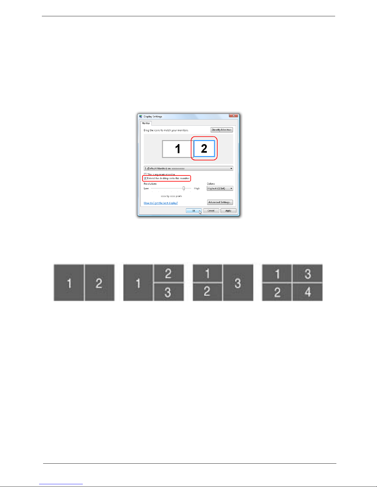
Acer GridVista (dual-display compatible)
NOTE: This feature is only available on certain models.
To enable the dual monitor feature of the notebook, first ensure that the second monitor is connected, then
select Start, Control Panel, Display and click on Settings. Select the secondary monitor (2) icon in the
display box and then click the check box Extend my windows desktop onto this monitor. Finally, click
Apply to confirm the new settings and click OK to complete the process.
Acer GridVista is a handy utility that offers four pre-defined display settings so you can view multiple windows
on the same screen. To access this function, please go to Start>All Programs and click on Acer GridVista.
You may choose any one of the four display settings indicated below:
Double (vertical), Triple (primary at left), Triple (primary at right), or Quad Acer Gridvista is dual-display
compatible, allowing two displays to be partitioned independently.
Acer Gridvista is dual-display compatible, allowing two displays to be partitioned independently.
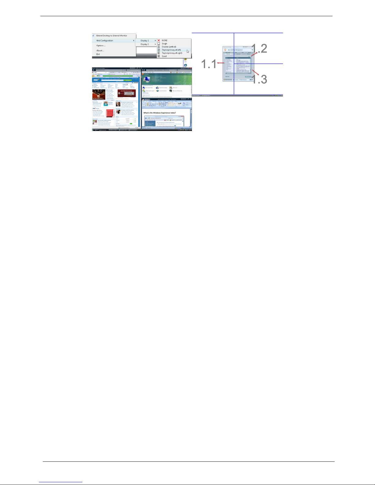
AcerGridVista is simple to set up:
1. Run Acer GridVista and select your preferred screen configuration for each display from the task bar.
2. Drag and drop each window into the appropriate grid.
3. Enjoy the convenience of a well-organized desktop.
Chapter 1 17
NOTE: Please ensure that the resolution setting of the second monitor is set to the manufacturer's
recommended value.
18 Chapter 1
Hardware Specifications and Configurations
Processor
Item Specification
CPU type 4810T/4810TZ/4410T (UMA):
Intel® Core™2 Duo Mobile SU9300 (1.20G)
Intel® Core™2 Solo SU3500 (1.4G);
Intel® Core™2 Duo SU9400 (1.4G)
Aspire 4810TG (DIS): Intel Core2 Solo SU3500 1.4G;
Intel® Core™2 Duo SU9400 (1.4G)
Core logic
CPU package Micro-FCBGA ( SU9300 and SU9400) and BGA (SU3500)
CPU core voltage 0.775 - 1.1 V
CPU Fan True Value Table
DTS(degree C) Fan Speed (rpm) Acoustic Level (dBA)
45-50 0-3000 29
55-66 0-3300 33
68-74 3300-3800 38
78-83 3800-4100 40
86-91 4100-4800 40
Mobile Intel
®
GS45 Express Chipset
Throttling 50%: On= 99 C; OFF=93 C
OS shut down at 105 C; H/W shot down at 110 .C
BIOS
Item Specification
BIOS vendor Insyde H2O
BIOS Version 1.06
System Memory
Item Specification
Memory controller Built-in
Memory size 0MB (no on-board memory)
DIMM socket number 2 sockets
Supports memory size per socket 2048MB
Supports maximum memory size 4G for 64bit OS (with two 2GB SODIMM)
Supports DIMM type DDR 3 Synchronous DRAM
Supports DIMM Speed 800/1066 MHz
Supports DIMM voltage 1.5V
Supports DIMM package 204-pin soDIMM
Memory module combinations You can install memory modules in any combinations as long as
they match the above specifications.
Chapter 1 19
Memory Combinations
Slot 1 Slot 2 Total Memory
0MB 1024MB 1024MB
0MB 2048MB 2048MB
1024MB 0MB 1024MB
1024MB 1024MB 2048MB
1024MB 2048MB 3072MB
2048MB 0MB 2048MB
2048MB 1024MB 3072MB
2048MB 2048MB 4096MB
NOTE: Above table lists some system memory configurations. You may combine DIMMs with various
capacities to form other combinations. On above table, the configuration of slot 1 and slot 2 could be
reversed.
Item Specification
LAN Chipset Atheros AR8131L
Supports LAN protocol 10/100/1000 Mbps
LAN connector type RJ45
LAN connector location Right side
Features Integrated 10/100 BASE-T transceiver
Wake on LAN support compliant with ACPI 2.0
PCI v2.2
Bluetooth Interface
Item Specification
Chipset Broadcom BCM2046
Data throughput 3 Mbps (full speed data rate)
Protocol Bluetooth 2.1
Interface USB 2.0
Connector type USB
Wireless Module
Item Specification
Chipset WLAN 802.11ABGN SHIRLEYPEAK1*2
WLAN 802.11ABG SHIRLEYPEAK1*2
Data throughput 11~54 Mbps, up to 270 Mbps for Draft-N
Protocol 802.11b+g, Draft-N
Interface PCI bus (mini PCI socket for wireless module)
20 Chapter 1
Hard Disk Drive Interface
Item
Vendor &
Model Name
Capacity
HGST
HTS543216L9A300
SEAGATE SATA
ST9160310AS F/
TOSHIBA
MK1655GSX
WD WD1600BEVT22ZCT0
HGST
HTS545025B9A300
SEAGATE
ST9250315AS
TOSHIBA
MK2555GSX
WD WD2500BEVT22ZCT0
HGST
HTS545032B9A300
SEAGATE
ST9320320A
TOSHIBA
MK3255GSX
WD WD3200BEVT22ZCT0
HGST
HTS545050B9A300
SEAGATE
ST9500325AS
TOSHIBA
MK5055GS
WD5000BEVT22ZAT0
160000 250000 320000 500000
(MB)
Bytes per
512 512 512 512
sector
Data heads 3/4 2 3 4
Drive Format
Disks 2 2 2 2
Spindle
5400 RPM 5400 RPM 5400 RPM 5400 RPM
speed
(RPM)
Performance Specifications
Buffer size 8MB 8MB 8MB 8MB
Interface SATA S ATA SATA SATA
Max. media
transfer rate
(disk-buffer,
Mbytes/s)
540 875
(Max. 3.0 Gbit/s
Buffer-host data
transfer)
875
(Max. 3.0 Gbit/s
Buffer-host data
transfer)
875
(Max. 3.0 Gbit/s
Buffer-host data
transfer)
DC Power Requirements
Voltage
5V(DC) +/- 5% 5V(DC) +/- 5% 5V(DC) +/- 5% 5V(DC) +/- 5%
tolerance
Optical Disc Drive
Item Specification
Vendor & model name TOSHIBA Super-Multi DRIVE DL 8X TS-U633A LF
Performance Specification With CD Diskette With DVD Diskette
Transfer rate (KB/sec) Sustained:
Buffer Memory 2MB
Interface SATA
Chapter 1 21
PANASONIC Super-Multi DRIVE DL 8X UJ862 LF
PANASONIC Super-Multi DRIVE DL 8X UJ862AC LF
HLDS Super-Multi DRIVE DL 8X GU10N LF
Sustained:
Max 3.6Mbytes/sec
Max 10.08Mbytes/sec
Optical Disc Drive
Item Specification
Applicable disc format Applicable disc format
CD: CD-DA, CD-ROM, CD-ROM XA, Photo CD (multi-session), Video
CD, Cd-Extra (CD+), CD-text
DVD: DVD-VIDEO, DVD-ROM, DVD-R (3.9GB, 4.7GB) DVD-R DL,
DVD-RW, DVD-RAM, DVD+R, DVD+R DL, DVD+RW
CD:
CD-DA (Red Book) - Standard Audio CD & CD-TEXT
CD-ROM (Yellow Book Mode1 & 2) - Standard Data
CD-ROM XA (Mode2 Form1 & 2) - Photo CD, Multi-Session
CD-I (Green Book, Mode2 Form1 & 2, Ready, Bridge)
CD-Extra/ CD-Plus (Blue Book) - Audio & Text/Video
Video-CD (White Book) - MPEG1 Video
CD-R (Orange Book Part)
CD-RW & HSRW (Orange Book Part Volume1 & Volume 2
Super Audio CD (SACD) Hybrid type
US & US+ RW
DVD:
DVD-ROM (Book 1.02), DVD-Dual
DVD-Video (Book 1.1)
DVD-R (Book 1.0, 3.9G)
DVD-R (Book 2.0, 4.7G) - General & Authoring
DVD+R (Version 1.0)
DVD+RW
DVD-RW (Non CPRM & CPRM)
DVD°”R Dual
Loading mechanism Load: Manual
Release: (a) Electrical Release (Release Button)
(b) Release by ATAPI command
(c) Emergency Release
Power Requirement
Input Voltage 5 V +/- 5% (Operating)
Audio Interface
Item Specification
Audio Controller Realtek Audio Codec ALC269X
Audio onboard or optional Built-in
Mono or Stereo Stereo
Resolution 18 bit stereo full duplex
Compatibility HD audio Interface; S/PDIF output for PCM or AC-3
Sampling rate 1Hz resolution VSR (Variable Sampling Rate)
Internal microphone Yes
Internal speaker / Quantity Yes/2 (1.5W speakers)
22 Chapter 1
content
 Loading...