


 Loading...
Aspire 5252/5552/5552G Series
Service Guide
Service guide files and updates are available on the ACER/CSD web; for more information, please refer to http://csd.acer.com.tw
PRINTED IN TAIWAN

Revision History
Please refer to the table below for the updates made on Aspire AS5552/AS5552G service guides.
Date |
Chapter |
Updates |
|
|
|
|
|
|
|
|
|
|
|
|
II

Copyright
Copyright © 2010 by Acer Incorporated. All rights reserved. No part of this publication may be reproduced, transmitted, transcribed, stored in a retrieval system, or translated into any language or computer language, in any form or by any means, electronic, mechanical, magnetic, optical, chemical, manual or otherwise, without the prior written permission of Acer Incorporated.
Disclaimer
The information in this guide is subject to change without notice.
Acer Incorporated makes no representations or warranties, either expressed or implied, with respect to the contents hereof and specifically disclaims any warranties of merchantability or fitness for any particular purpose. Any Acer Incorporated software described in this manual is sold or licensed "as is". Should the programs prove defective following their purchase, the buyer (and not Acer Incorporated, its distributor, or its dealer) assumes the entire cost of all necessary servicing, repair, and any incidental or consequential damages resulting from any defect in the software.
Acer is a registered trademark of Acer Corporation.
Other brand and product names are trademarks and/or registered trademarks of their respective holders.
III

IV

Conventions
The following conventions are used in this manual:
SCREEN MESSAGES |
Denotes actual messages that appear |
|
on screen. |
|
|
NOTE |
Gives bits and pieces of additional |
|
information related to the current |
|
topic. |
|
|
WARNING |
Alerts you to any damage that might |
|
result from doing or not doing specific |
|
actions. |
|
|
CAUTION |
Gives precautionary measures to |
|
avoid possible hardware or software |
|
problems. |
|
|
IMPORTANT |
Reminds you to do specific actions |
|
relevant to the accomplishment of |
|
procedures. |
|
|
NOTE: This symbol where placed in the Service Guide designates a component that should be recycled according to the local regulations.
V

Preface
Before using this information and the product it supports, please read the following general information.
1.This Service Guide provides you with all technical information relating to the BASIC CONFIGURATION decided for Acer's "global" product offering. To better fit local market requirements and enhance product competitiveness, your regional office MAY have decided to extend the functionality of a machine (e.g. add-on card, modem, or extra memory capability). These LOCALIZED FEATURES will NOT be covered in this generic service guide. In such cases, please contact your regional offices or the responsible personnel/channel to provide you with further technical details.
2.Please note WHEN ORDERING FRU PARTS, that you should check the most up-to-date information available on your regional web or channel. If, for whatever reason, a part number change is made, it will not be noted in the printed Service Guide. For ACER-AUTHORIZED SERVICE PROVIDERS, your Acer office may have a DIFFERENT part number code to those given in the FRU list of this printed Service Guide. You MUST use the list provided by your regional Acer office to order FRU parts for repair and service of customer machines.
VI

Table of Contents
System Specifications |
1 |
Features . . . . . . . . . . . . . . . . . . . . . . . . . . . . . . . . . . . . . . . . . . . . . . . . . . . . . . . . . . . .1 System Block Diagram . . . . . . . . . . . . . . . . . . . . . . . . . . . . . . . . . . . . . . . . . . . . . . . . .6 Discrete Model . . . . . . . . . . . . . . . . . . . . . . . . . . . . . . . . . . . . . . . . . . . . . . . . . . .6 UMA Model . . . . . . . . . . . . . . . . . . . . . . . . . . . . . . . . . . . . . . . . . . . . . . . . . . . . . .7 Your Acer Notebook tour . . . . . . . . . . . . . . . . . . . . . . . . . . . . . . . . . . . . . . . . . . . . . . .8 Front View . . . . . . . . . . . . . . . . . . . . . . . . . . . . . . . . . . . . . . . . . . . . . . . . . . . . . . .8 Rear View . . . . . . . . . . . . . . . . . . . . . . . . . . . . . . . . . . . . . . . . . . . . . . . . . . . . . . .9 Left View . . . . . . . . . . . . . . . . . . . . . . . . . . . . . . . . . . . . . . . . . . . . . . . . . . . . . . . .9 Right View . . . . . . . . . . . . . . . . . . . . . . . . . . . . . . . . . . . . . . . . . . . . . . . . . . . . . .10 Base View . . . . . . . . . . . . . . . . . . . . . . . . . . . . . . . . . . . . . . . . . . . . . . . . . . . . . .11 Indicators . . . . . . . . . . . . . . . . . . . . . . . . . . . . . . . . . . . . . . . . . . . . . . . . . . . . . .11 Touchpad Basics . . . . . . . . . . . . . . . . . . . . . . . . . . . . . . . . . . . . . . . . . . . . . . . .12 Using the Keyboard . . . . . . . . . . . . . . . . . . . . . . . . . . . . . . . . . . . . . . . . . . . . . . . . . .13 Lock Keys and embedded numeric keypad . . . . . . . . . . . . . . . . . . . . . . . . . . . .13 Windows Keys . . . . . . . . . . . . . . . . . . . . . . . . . . . . . . . . . . . . . . . . . . . . . . . . . .14 Hot Keys . . . . . . . . . . . . . . . . . . . . . . . . . . . . . . . . . . . . . . . . . . . . . . . . . . . . . . .15
Hardware Specifications and Configurations . . . . . . . . . . . . . . . . . . . . . . . . . . . . . . .16
System Utilities |
29 |
BIOS Setup Utility . . . . . . . . . . . . . . . . . . . . . . . . . . . . . . . . . . . . . . . . . . . . . . . . . . . .29
Navigating the BIOS Utility . . . . . . . . . . . . . . . . . . . . . . . . . . . . . . . . . . . . . . . . .29
Aspire AS5552/AS5552G BIOS . . . . . . . . . . . . . . . . . . . . . . . . . . . . . . . . . . . . . . . . .30
Information . . . . . . . . . . . . . . . . . . . . . . . . . . . . . . . . . . . . . . . . . . . . . . . . . . . . .30
Main . . . . . . . . . . . . . . . . . . . . . . . . . . . . . . . . . . . . . . . . . . . . . . . . . . . . . . . . . .31
Security . . . . . . . . . . . . . . . . . . . . . . . . . . . . . . . . . . . . . . . . . . . . . . . . . . . . . . . .32
Boot . . . . . . . . . . . . . . . . . . . . . . . . . . . . . . . . . . . . . . . . . . . . . . . . . . . . . . . . . . .35
Exit . . . . . . . . . . . . . . . . . . . . . . . . . . . . . . . . . . . . . . . . . . . . . . . . . . . . . . . . . . .36
BIOS Flash Utilities . . . . . . . . . . . . . . . . . . . . . . . . . . . . . . . . . . . . . . . . . . . . . . . . . . .37
DOS Flash Utility . . . . . . . . . . . . . . . . . . . . . . . . . . . . . . . . . . . . . . . . . . . . . . . . .38
WinFlash Utility . . . . . . . . . . . . . . . . . . . . . . . . . . . . . . . . . . . . . . . . . . . . . . . . . .40
Remove HDD/BIOS Password Utilities . . . . . . . . . . . . . . . . . . . . . . . . . . . . . . . . . . . .41
Machine Disassembly and Replacement |
45 |
Disassembly Requirements . . . . . . . . . . . . . . . . . . . . . . . . . . . . . . . . . . . . . . . . . . . |
.45 |
Pre-disassembly Instructions . . . . . . . . . . . . . . . . . . . . . . . . . . . . . . . . . . . . . . |
.46 |
Disassembly Process . . . . . . . . . . . . . . . . . . . . . . . . . . . . . . . . . . . . . . . . . . . . . |
47 |
External Module Disassembly Process . . . . . . . . . . . . . . . . . . . . . . . . . . . . . . . . . . . |
48 |
External Modules Disassembly Flowchart . . . . . . . . . . . . . . . . . . . . . . . . . . . . . |
48 |
Removing the Battery Pack . . . . . . . . . . . . . . . . . . . . . . . . . . . . . . . . . . . . . . . . |
49 |
Removing the SD Dummy Card . . . . . . . . . . . . . . . . . . . . . . . . . . . . . . . . . . . . . |
50 |
Removing the Keyboard . . . . . . . . . . . . . . . . . . . . . . . . . . . . . . . . . . . . . . . . . . . |
51 |
Removing the ODD Module . . . . . . . . . . . . . . . . . . . . . . . . . . . . . . . . . . . . . . . . |
53 |
Removing the Logic Lower Door . . . . . . . . . . . . . . . . . . . . . . . . . . . . . . . . . . . . . |
55 |
Removing the 3G Cover (Discrete Only) . . . . . . . . . . . . . . . . . . . . . . . . . . . . . . |
56 |
Removing the DIMM Module . . . . . . . . . . . . . . . . . . . . . . . . . . . . . . . . . . . . . . . |
57 |
Removing the WLAN Module . . . . . . . . . . . . . . . . . . . . . . . . . . . . . . . . . . . . . . . |
58 |
Removing the HDD Module . . . . . . . . . . . . . . . . . . . . . . . . . . . . . . . . . . . . . . . . |
60 |
Removing the RTC Battery (UMA Only) . . . . . . . . . . . . . . . . . . . . . . . . . . . . . . . |
62 |
Main Unit Disassembly Process . . . . . . . . . . . . . . . . . . . . . . . . . . . . . . . . . . . . . . . . . |
63 |
Main Unit Disassembly Flowchart . . . . . . . . . . . . . . . . . . . . . . . . . . . . . . . . . . . . |
63 |
Removing the Upper Cover . . . . . . . . . . . . . . . . . . . . . . . . . . . . . . . . . . . . . . . . |
64 |
Removing the Speaker Module . . . . . . . . . . . . . . . . . . . . . . . . . . . . . . . . . . . . . . |
68 |
Removing the Power Board . . . . . . . . . . . . . . . . . . . . . . . . . . . . . . . . . . . . . . . . |
69 |
VII

Table of Contents |
|
Removing the Touchpad FFC . . . . . . . . . . . . . . . . . . . . . . . . . . . . . . . . . . . . . |
. .70 |
Removing the Card Reader Board (Discrete Only) . . . . . . . . . . . . . . . . . . . . . |
. .71 |
Removing the USB Board . . . . . . . . . . . . . . . . . . . . . . . . . . . . . . . . . . . . . . . . . |
.73 |
Removing the Bluetooth Module . . . . . . . . . . . . . . . . . . . . . . . . . . . . . . . . . . . . |
.75 |
Removing the ODD Connector Board (UMA Only) . . . . . . . . . . . . . . . . . . . . . . |
.77 |
Removing the Mainboard . . . . . . . . . . . . . . . . . . . . . . . . . . . . . . . . . . . . . . . . . |
.78 |
Removing the Thermal Module . . . . . . . . . . . . . . . . . . . . . . . . . . . . . . . . . . . . . |
.82 |
Removing the CPU . . . . . . . . . . . . . . . . . . . . . . . . . . . . . . . . . . . . . . . . . . . . . . |
.84 |
Removing the LCD Assembly . . . . . . . . . . . . . . . . . . . . . . . . . . . . . . . . . . . . . . |
.85 |
Removing the DC-IN Assembly . . . . . . . . . . . . . . . . . . . . . . . . . . . . . . . . . . . . |
.88 |
LCD Module Disassembly Process . . . . . . . . . . . . . . . . . . . . . . . . . . . . . . . . . . . . . |
.89 |
LCD Module Disassembly Flowchart . . . . . . . . . . . . . . . . . . . . . . . . . . . . . . . . |
.89 |
Removing the LCD Bezel . . . . . . . . . . . . . . . . . . . . . . . . . . . . . . . . . . . . . . . . . |
.90 |
Removing the Camera Module . . . . . . . . . . . . . . . . . . . . . . . . . . . . . . . . . . . . . |
.91 |
Removing the Inverter Board (LCD Only) . . . . . . . . . . . . . . . . . . . . . . . . . . . . . |
.92 |
Removing the LCD/LED Panel . . . . . . . . . . . . . . . . . . . . . . . . . . . . . . . . . . . . . |
.94 |
Removing the LCD Brackets . . . . . . . . . . . . . . . . . . . . . . . . . . . . . . . . . . . . . . . |
.95 |
Removing the LVDS cable . . . . . . . . . . . . . . . . . . . . . . . . . . . . . . . . . . . . . . . . |
.96 |
Removing the Microphone Cable . . . . . . . . . . . . . . . . . . . . . . . . . . . . . . . . . . . |
.97 |
Removing the Antennas . . . . . . . . . . . . . . . . . . . . . . . . . . . . . . . . . . . . . . . . . . |
.99 |
LCD Module Reassembly Procedure . . . . . . . . . . . . . . . . . . . . . . . . . . . . . . . . . . . . |
101 |
Replacing the Antennas . . . . . . . . . . . . . . . . . . . . . . . . . . . . . . . . . . . . . . . . . . |
101 |
Replacing the Microphone Cable . . . . . . . . . . . . . . . . . . . . . . . . . . . . . . . . . . . |
103 |
Replacing the LVDS Cable . . . . . . . . . . . . . . . . . . . . . . . . . . . . . . . . . . . . . . . . |
105 |
Replacing the LCD Brackets . . . . . . . . . . . . . . . . . . . . . . . . . . . . . . . . . . . . . . . |
106 |
Replacing the LCD/LED Panel . . . . . . . . . . . . . . . . . . . . . . . . . . . . . . . . . . . . . |
107 |
Replacing the Inverter Board (LCD Only) . . . . . . . . . . . . . . . . . . . . . . . . . . . . . |
108 |
Replacing the Camera Module . . . . . . . . . . . . . . . . . . . . . . . . . . . . . . . . . . . . . |
110 |
Replacing the LCD Bezel . . . . . . . . . . . . . . . . . . . . . . . . . . . . . . . . . . . . . . . . . |
111 |
Main Module Reassembly Procedure . . . . . . . . . . . . . . . . . . . . . . . . . . . . . . . . . . . . |
112 |
Replacing the DC-IN Assembly . . . . . . . . . . . . . . . . . . . . . . . . . . . . . . . . . . . . |
112 |
Replacing the LCD Assembly . . . . . . . . . . . . . . . . . . . . . . . . . . . . . . . . . . . . . . |
113 |
Replacing the CPU . . . . . . . . . . . . . . . . . . . . . . . . . . . . . . . . . . . . . . . . . . . . . . |
116 |
Replacing the Thermal Module . . . . . . . . . . . . . . . . . . . . . . . . . . . . . . . . . . . . . |
117 |
Replacing the Mainboard . . . . . . . . . . . . . . . . . . . . . . . . . . . . . . . . . . . . . . . . . |
120 |
Replacing the ODD Connector Board (UMA Only) . . . . . . . . . . . . . . . . . . . . . . |
123 |
Replacing the Bluetooth Board . . . . . . . . . . . . . . . . . . . . . . . . . . . . . . . . . . . . . |
124 |
Replacing the USB Board . . . . . . . . . . . . . . . . . . . . . . . . . . . . . . . . . . . . . . . . . |
125 |
Replacing the Card Reader Board (Discrete Only) . . . . . . . . . . . . . . . . . . . . . . |
127 |
Replacing the Touchpad FFC . . . . . . . . . . . . . . . . . . . . . . . . . . . . . . . . . . . . . . |
129 |
Replacing the Power Board . . . . . . . . . . . . . . . . . . . . . . . . . . . . . . . . . . . . . . . |
130 |
Replacing the Speaker Module . . . . . . . . . . . . . . . . . . . . . . . . . . . . . . . . . . . . . |
131 |
Replacing the Upper Cover . . . . . . . . . . . . . . . . . . . . . . . . . . . . . . . . . . . . . . . . |
132 |
Replacing the RTC Battery (UMA Only) . . . . . . . . . . . . . . . . . . . . . . . . . . . . . . |
136 |
Replacing the HDD Module . . . . . . . . . . . . . . . . . . . . . . . . . . . . . . . . . . . . . . . |
137 |
Replacing the WLAN Module . . . . . . . . . . . . . . . . . . . . . . . . . . . . . . . . . . . . . . |
139 |
Replacing the DIMM Modules . . . . . . . . . . . . . . . . . . . . . . . . . . . . . . . . . . . . . . |
140 |
Replacing the 3G Cover (Discrete Only) . . . . . . . . . . . . . . . . . . . . . . . . . . . . . . |
141 |
Replacing the Lower Logic Door . . . . . . . . . . . . . . . . . . . . . . . . . . . . . . . . . . . . |
142 |
Replacing the ODD Module . . . . . . . . . . . . . . . . . . . . . . . . . . . . . . . . . . . . . . . |
143 |
Replacing the Keyboard . . . . . . . . . . . . . . . . . . . . . . . . . . . . . . . . . . . . . . . . . . |
145 |
Replacing the SD Dummy Card . . . . . . . . . . . . . . . . . . . . . . . . . . . . . . . . . . . . |
146 |
Replacing the Battery . . . . . . . . . . . . . . . . . . . . . . . . . . . . . . . . . . . . . . . . . . . . |
147 |
VIII

Table of Contents
Troubleshooting |
149 |
Common Problems . . . . . . . . . . . . . . . . . . . . . . . . . . . . . . . . . . . . . . . . . . . . . . . . . .149
Power On Issue . . . . . . . . . . . . . . . . . . . . . . . . . . . . . . . . . . . . . . . . . . . . . . . .150
No Display Issue . . . . . . . . . . . . . . . . . . . . . . . . . . . . . . . . . . . . . . . . . . . . . . . .151
Random Loss of BIOS Settings . . . . . . . . . . . . . . . . . . . . . . . . . . . . . . . . . . . .152
LCD Failure . . . . . . . . . . . . . . . . . . . . . . . . . . . . . . . . . . . . . . . . . . . . . . . . . . . .153
Built-In Keyboard Failure . . . . . . . . . . . . . . . . . . . . . . . . . . . . . . . . . . . . . . . . .153
Touchpad Failure . . . . . . . . . . . . . . . . . . . . . . . . . . . . . . . . . . . . . . . . . . . . . . .154
Internal Speaker Failure . . . . . . . . . . . . . . . . . . . . . . . . . . . . . . . . . . . . . . . . . .154
HDD Not Operating Correctly . . . . . . . . . . . . . . . . . . . . . . . . . . . . . . . . . . . . . .156
ODD Failure . . . . . . . . . . . . . . . . . . . . . . . . . . . . . . . . . . . . . . . . . . . . . . . . . . .157
Wireless Function Failure . . . . . . . . . . . . . . . . . . . . . . . . . . . . . . . . . . . . . . . . .160
Thermal Unit Failure . . . . . . . . . . . . . . . . . . . . . . . . . . . . . . . . . . . . . . . . . . . . .160
External Mouse Failure . . . . . . . . . . . . . . . . . . . . . . . . . . . . . . . . . . . . . . . . . . .161
Other Failures . . . . . . . . . . . . . . . . . . . . . . . . . . . . . . . . . . . . . . . . . . . . . . . . . .161
Intermittent Problems . . . . . . . . . . . . . . . . . . . . . . . . . . . . . . . . . . . . . . . . . . . . . . . .162
Undetermined Problems . . . . . . . . . . . . . . . . . . . . . . . . . . . . . . . . . . . . . . . . . . . . . .162
Post Codes . . . . . . . . . . . . . . . . . . . . . . . . . . . . . . . . . . . . . . . . . . . . . . . . . . . . . . . .163
Jumper and Connector Locations |
167 |
Top View (Discrete) . . . . . . . . . . . . . . . . . . . . . . . . . . . . . . . . . . . . . . . . . . . . |
.167 |
Bottom View (Discrete) . . . . . . . . . . . . . . . . . . . . . . . . . . . . . . . . . . . . . . . . . . |
.168 |
Top View (UMA) . . . . . . . . . . . . . . . . . . . . . . . . . . . . . . . . . . . . . . . . . . . . . . . |
.169 |
Bottom View (UMA) . . . . . . . . . . . . . . . . . . . . . . . . . . . . . . . . . . . . . . . . . . . . |
.170 |
Power Board(Discrete) . . . . . . . . . . . . . . . . . . . . . . . . . . . . . . . . . . . . . . . . . . |
.171 |
Power Board(UMA) . . . . . . . . . . . . . . . . . . . . . . . . . . . . . . . . . . . . . . . . . . . . . |
.172 |
USB Board . . . . . . . . . . . . . . . . . . . . . . . . . . . . . . . . . . . . . . . . . . . . . . . . . . . |
.173 |
Card Reader Board (Discrete only) . . . . . . . . . . . . . . . . . . . . . . . . . . . . . . . . . |
.173 |
Clearing Password Check and BIOS Recovery . . . . . . . . . . . . . . . . . . . . . . . . . . . |
.174 |
Clearing Password Check . . . . . . . . . . . . . . . . . . . . . . . . . . . . . . . . . . . . . . . . |
.174 |
Clear CMOS Jumper . . . . . . . . . . . . . . . . . . . . . . . . . . . . . . . . . . . . . . . . . . . . |
.174 |
BIOS Recovery by Crisis Disk . . . . . . . . . . . . . . . . . . . . . . . . . . . . . . . . . . . . |
.175 |
FRU (Field Replaceable Unit) List |
177 |
Aspire AS5552/AS5552G Exploded Diagrams . . . . . . . . . . . . . . . . . . . . . . . . . . . . .178
Main Assembly . . . . . . . . . . . . . . . . . . . . . . . . . . . . . . . . . . . . . . . . . . . . . . . . .178
Upper Assembly . . . . . . . . . . . . . . . . . . . . . . . . . . . . . . . . . . . . . . . . . . . . . . . .179
LCD Assembly . . . . . . . . . . . . . . . . . . . . . . . . . . . . . . . . . . . . . . . . . . . . . . . . .180
LED Assembly . . . . . . . . . . . . . . . . . . . . . . . . . . . . . . . . . . . . . . . . . . . . . . . . .181
Aspire AS5552/AS5552G FRU List . . . . . . . . . . . . . . . . . . . . . . . . . . . . . . . . . . . . .182
Screw List . . . . . . . . . . . . . . . . . . . . . . . . . . . . . . . . . . . . . . . . . . . . . . . . . . . . . . . . .199
Model Definition and Configuration |
200 |
Test Compatible Components |
239 |
Microsoft® Windows® 7 Environment Test . . . . . . . . . . . . . . . . . . . . . . . . . . . . . . |
.240 |
Online Support Information |
245 |
Index |
247 |
IX

Table of Contents
X
Chapter 1
System Specifications
Features
Below is a brief summary of the computer’s many features:
NOTE: Items denoted with an (*) are only available for selected models.
Operating System
•Genuine Windows® 7 Home Premium 64-bit
•Genuine Windows® 7 Home Basic 64-bit
Platform
Aspire 5252
•AMD V Series processor V140 (512 KB L2 cache, 2.30 GHz, DDR3 1066 MHz, 25 W)
•AMD M880G Chipset
Aspire 5552/Aspire 5552G
•AMD Phenom™ II quad-core mobile processor N950 (2 MB L2 cache, 2.1 GHz, DDR3 1333 MHz, 35 W)
•AMD Phenom™ II triple-core mobile processor N850 (1.5 MB L2 cache, 2.20GHz, DDR3 1333 MHz, 35 W)
•AMD Turion™ II dual-core mobile processor P540 (2 MB L2 cache, 2.40GHz, DDR3 1066 MHz, 25 W)
•AMD Athlon™ II dual-core processor P340/N350 (1 MB L2 cache, 2.20/2.40-GHz, DDR3 1066 MHz, 25/35 W)
•AMD M880G Chipset
System Memory
•Dual-channel DDR3 SDRAM support:
• Up to 4 GB of DDR3 system memory, upgradable to 8 GB using two soDIMM modules
Display
•15.6" HD 1366 x 768 pixel resolution, high-brightness (200-nit) Acer CineCrystal™ TFT LCD
•16:9 aspect ratio
Chapter 1 |
1 |

Graphics
Aspire 5252/5552
•ATI Radeon™ HD 4250 Graphics with 256 MB of dedicated system memory, supporting Unified Video Decoder 2 (UVD2), OpenGL® 2.0, OpenEXR High Dynamic-Range (HDR) technology, Shader Model 4.1, Microsoft® DirectX® 10.1
•Dual independent display support
•16.7 million colors
•External resolution / refresh rate:
•VGA port up to 2456 x 1536: 60 Hz
•HDMI™ port up to 1920 x 1080: 60 Hz
•MPEG-2/DVD decoding
•WMV9 (VC-1) and H.264 (AVC) decoding
•HDMI™ (High-Definition Multimedia Interface) with HDCP (High-bandwidth Digital Content Protection) support
Aspire 5552G
•ATI Mobility Radeon™ HD 5650 with 1024 MB of dedicated DDR3 VRAM, supporting Unified Video Decoder (UVD), OpenEXR High Dynamic-Range (HDR) technology, Shader Model 5.0, Microsoft® DirectX® 11, OpenGL® 3.1, OpenCL™ 1.1
•ATI Mobility Radeon™ HD 5470 with 512 MB of dedicated DDR3 VRAM, supporting Unified Video Decoder (UVD), OpenEXR High Dynamic-Range (HDR) technology, Shader Model 5.0, Microsoft® DirectX® 11, OpenGL ® 3.1, OpenCL™ 1.1
•Dual independent display support
•16.7 million colors
•External resolution / refresh rates:
•VGA port up to 2048 x 1536: 85 Hz
•HDMI™ port up to 1920 x 1080: 60 Hz
•MPEG-2/DVD decoding
•WMV9 (VC-1) and H.264 (AVC) decoding
•Microsoft® DirectX® Video Acceleration (DXVA) application interface (API)
•HDMI™ (High-Definition Multimedia Interface) with HDCP (High-bandwidth Digital Content Protection) support
Audio
•Built-in Acer mono speaker
•High-definition audio support
•Built-in microphone
•MS-Sound compatible
Storage
•Hard disk drive:
•160/250/320/500/640/750 GB or larger
•2-in-1 card reader, supporting:
•Secure Digital™ (SD), MultiMediaCard™ (MMC)
2 |
Chapter 1 |

Optical Media Drive
•8X DVD-Super Multi double-layer drive:
•Read: 24X CD-ROM, 24X CD-R, 24X CD-RW, 8X DVD-ROM, 8X DVD-R, 8X DVD+R, 6X DVD-ROM DL, 6X DVD-R DL, 6X DVD+R DL, 6X DVD-RW, 6X DVD+RW, 5X DVD-RAM
•Write: 24X CD-R, 16X CD-RW, 8X DVD-R, 8X DVD+R, 4X DVD-R DL, 4X DVD+R DL, 6X DVD-RW, 8X DVD+RW, 5X DVD-RAM
Communication
•Acer Video Conference, featuring:
•Acer Crystal Eye webcam with 1280 x 1024 resolution
•WLAN:
•Acer InviLink™ Nplify™ 802.11b/g/n Wi-Fi CERTIFIED™
•Acer InviLink™ 802.11b/g Wi-Fi CERTIFIED™
•Supporting Acer SignalUp™ wireless technology
•WPAN:
•Bluetooth® 2.1+EDR
•Bluetooth® 3.0+HS
•LAN:
•Gigabit Ethernet, Wake-on-LAN ready
Privacy Control
•BIOS user, supervisor, HDD passwords
•Kensington lock slot
Dimensions and Weight
•Dimensions
•381 (W) x 253 (D) x 25/34 (H) mm 15 x 9.96 x 0.98/1.33 inches)
•Weight
•2.6 kg (5.74 lbs.) with 6-cell battery pack
Power Subsystem
ACPI 3.0 CPU power management standard: supports Standby and Hibernation power-saving modes
•Power adapter
•3-pin 65 W AC adapter
•108 (W) x 46 (D) x 29.5 (H) mm (4.25 x 1.81 x 1.16 inches)
•225 g (0.49 lbs.) with 180 cm DC cable
•Battery
•48.8 W 4400 mAh 6-cell Li-ion standard battery pack
•Battery life: 3 hours and 20 minutes
•ENERGY STAR®
Chapter 1 |
3 |

Special Keys and Controls
•Keyboard
•103-/104-/107-key Acer FineTip keyboard with independent standard numeric keypad, international language support
•Touchpad
•Multi-gesture touchpad, supporting two-finger scroll, pinch, rotate, flip
•Media keys
•Media control keys (printed on keyboard): play/pause, stop, previous, next, volume up, volume down
I/O Interface
•2-in-1 card reader (SD™, MMC)
•Three USB 2.0 ports
•HDMI™ port with HDCP support
•External display (VGA) port
•Headphone/speaker/line-out jack
•Microphone-in jack
•Ethernet (RJ-45) port
•DC-in jack for AC adapter
Software
•Productivity
•Acer Backup Manager
•Acer ePower Management
•Acer eRecovery Management
•Adobe® Flash® Player 10
•Adobe® Reader® 9.1
•eSobi™
•Google™ Setup
•Google Toolbar™
•Microsoft® Office 2010 preloaded (purchase a product key to activate)
•Microsoft® Office Starter 2010
•Norton™ Online Backup
•Security
•McAfee® Internet Security Suite Trial
•MyWinLocker® (except China, Hong Kong)
•Multimedia
•Corel® WinDVD (for models with Windows® 7 Starter and Basic)
•NTI Media Maker™
•Gaming
•Oberon GameZone (except US, Canada, Hong Kong, Korea)
•WildTangent® (US, Canada only)
•Communication and ISP
•Microsoft® Silverlight™
•Windows Live™ Essentials - Wave 3.2 (Mail, Photo Gallery, Live™ Messenger, Movie Maker, Writer)
4 |
Chapter 1 |

•Utilities and tools
•Acer Accessory Store (Belgium, France, Germany, Italy, Netherlands, Spain, Sweden, UK only)
•Acer Identity Card
•Acer Registration
•Acer Updater
•eBay® shortcut 2009 (Canada, France, Germany, Italy, Mexico, Spain, UK, US only)
•Netflix shortcut (US only)
Optional Items
•1/2/4 GB DDR3 1066 MHz soDIMM module
•6-cell Li-ion battery pack
•3-pin 65 W AC adapter
•External USB 56K modem
Warranty
•One-year International Travelers Warranty (ITW)
Environment
•Temperature:
•Operating: 5°C to 35°C
•Non-operating: -20°C to 65°C
•Humidity (non-condensing):
•Operating: 20% to 80%
•Non-operating: 20% to 80%
Chapter 1 |
5 |

System Block Diagram
Discrete Model
VRAM 1GB |
|
Danube |
|
|
|
|
AMD S1G4 Processor |
|
|
|
|||
64M16 x 8 |
Memory BUS(DDR3) |
204pin DDRIII-SO-DIMM X2 |
||||
|
uPGA-638 Package |
|||||
|
|
Dual Channel |
||||
DDR3 |
|
BANK 0, 1, 2, 3 |
||||
|
Champlain |
|||||
|
1.5V DDRIII 800~1333MHz |
|||||
ATI M97 |
|
|
|
|||
|
Hyper Transport Link |
|
|
|
||
Madisan/Park |
|
|
|
|
||
uFCBGA-962 |
PCI-Express x 16 |
16 x 16 |
|
|
|
|
|
Gen2 |
ATI RS880M |
Thermal Sensor |
Clock Generator |
||
|
|
ADM1032 |
ICS9LPRS488 |
|||
LVDS |
|
|
||||
|
uFCBGA-528 |
|
|
|
||
|
|
|
|
|
||
CRT |
|
|
|
|
|
|
|
|
|
A link Express2 |
|
USB |
CMOS |
Bluetooth |
Mini |
3G/GPS |
|
Card |
||||
|
|
|
Gen1 |
|
conn |
Camera |
Conn |
card |
WWAN |
|
Reader |
||||
|
|
||||||||||||||
HDMI Conn. |
|
|
|
|
X 3 |
|
|
|
<Option> |
|
(WL)X1 |
|
<Option> |
|
|
|
|
|
|
|
|
|
|
||||||||
|
|
|
|
|
|||||||||||
|
|
|
|
USB port 0,1,2 |
USB port 5 |
|
USB port 12 |
|
USB port 8 |
USB port 9 |
|
USB port 6 |
|||
|
|
|
|
|
|
|
|
|
|
|
|
|
|
|
|
|
|
ATI SB820M |
3.3V 48MHz |
|
|
|
|
|
USB |
|
|
|
|
|
||||||||
|
|
|
|
|
|
|
|
|
|
|
|
|
|
|
|
|
|
uFCBGA-605 |
|
3.3V 24.576MHz/48Mhz |
HD Audio |
|
|
|
|
|
||||||||||||
|
|
|
MINI Card 1 |
|
LAN(GbE) |
|
|
|
|
|
|
|
|
|
|
|
|
|
|
|
|
|
|
|
||||||||||||||
|
|
|
|
Broadcom |
|
|
|
|
|
|
|
|
|
|
|
|
|
|
|
|
|
|
|
|
|
|
|
|
||||||||||
|
|
|
|
WLAN |
|
|
BCM57780 |
|
|
|
|
|
|
|
|
|
S-ATA |
Gen2 |
|
|
|
|
|
|
|
|
|
|
||||||||||
|
|
|
|
GPP1 |
|
|
GPP0 |
|
|
|
|
|
|
|
|
|
|
|
|
|
|
|
|
|
|
|
|
|
|
HDA Codec |
|
|
||||||
|
|
|
|
|
|
|
|
|
|
|
|
|
|
|
|
|
|
|
|
|
|
|
|
|
|
|
|
|
|
|
|
|
|
ALC272X |
|
|
||
|
|
|
|
|
|
|
|
|
|
RJ45 |
|
|
|
|
|
|
LPC BUS |
SATA HDD |
|
CDROM |
|
|
|
|
|
|
|
|||||||||||
|
|
|
|
|
|
|
|
|
|
|
|
|
|
|
|
|
|
|
|
|
|
|
|
|
|
|
||||||||||||
|
|
|
|
|
|
|
|
|
|
|
|
|
|
|
|
|
|
|
|
|
|
|
|
Conn. |
|
|
Conn. |
|
|
|
|
|
|
|
|
|||
|
|
|
|
|
|
|
|
|
|
|
|
|
|
|
|
|
|
|
|
|
|
|
|
|
|
|
|
|
Audio AMP |
|
|
|
||||||
|
|
|
|
|
|
|
|
|
|
|
|
|
|
|
|
|
|
|
|
|
|
|
|
port 0 |
|
|
port 1 |
|
|
|
|
|
|
|||||
LED |
|
|
|
|
|
|
|
|
|
|
|
|
|
ENE KB926 |
|
|
|
|
|
|
|
|
|
|
|
|
|
|
|
|
||||||||
|
Fan Control |
|
|
|
|
|
|
|
|
|
|
|
|
|
|
|
|
|
|
|||||||||||||||||||
|
|
|
|
|
|
|
|
|
|
|
|
|
|
|
|
|
|
|
|
|
|
|
|
|
|
|
|
|
Phone Jack x2 |
|
||||||||
|
|
|
|
|
|
|
|
|
|
|
|
|
|
|
|
|
|
|
|
|
|
|
|
|
|
|
|
|
|
|
|
|
|
|
||||
RTC CKT. |
|
|
|
|
|
|
|
|
|
|
Touch Pad |
|
|
Int.KBD |
|
|
|
|
|
|
|
|
|
|
|
|
|
|
||||||||||
Extend Card/B |
|
|
|
|
|
|
|
|
|
|
|
|
|
|
|
|
|
|||||||||||||||||||||
|
|
|
|
|
|
|
|
|
|
|
|
|
|
|
|
|
|
|
|
|
|
|
||||||||||||||||
|
|
|
|
|
|
|
|
|
|
|
|
|
|
|
|
|
|
|
|
|
|
|
|
|
|
|
|
|
|
|
||||||||
|
|
|
|
|
|
|
|
|
|
|
|
|
|
|
|
|
|
|
|
|
|
|
|
|
|
|
|
|
|
|
||||||||
|
|
|
|
|
|
|
1. USB X2 |
|
|
|
|
|
|
|
|
|
|
|
|
|
|
|
|
|
|
|
|
|
|
|
|
|||||||
LID SW / MEDIA/B |
|
EC I/O Buffer |
|
|
BIOS |
|
|
|
|
|
|
|
|
|
|
|
|
|
|
|
||||||||||||||||||
|
|
|
|
|
|
|
|
|
|
|
|
|
|
|
|
|
|
|
|
|
|
|
|
|
|
|||||||||||||
2.Cardreader RTS5160
Power On/Off CKT.
DC/DC Interface CKT.
Power Circuit
6 |
Chapter 1 |

UMA Model
Danube
|
|
|
|
|
|
|
|
|
|
|
|
|
|
|
|
|
|
|
|
|
|
AMD S1G4 Processor |
|
Memory BUS(DDR3) |
|
|
|
|
|
|
|
|
|
|
|
|
|
|
|||||||||||||||||||||
|
|
|
|
|
|
|
|
|
|
|
|
|
|
|
|
|
|
|
|
|
|
|
|
|
|
|
|
|
|
|
|
|
|
|
|
|
|||||||||||||||||||||||
|
|
|
|
|
|
|
|
|
|
|
|
|
|
|
|
|
|
|
|
|
|
|
|
uPGA-638 Package |
|
204pin DDRIII-SO-DIMM X2 |
|
|
|||||||||||||||||||||||||||||||
|
|
|
|
|
|
|
|
|
|
|
|
|
|
|
|
|
|
|
|
|
|
|
|
|
|
|
Dual Channel |
|
|||||||||||||||||||||||||||||||
|
|
|
|
|
|
|
|
|
|
|
|
|
|
|
|
|
|
|
|
|
|
|
|
|
|
|
|
|
|
|
|
|
|
|
|
|
|
|
|
|
|||||||||||||||||||
|
|
|
|
|
|
|
|
|
|
|
|
|
|
|
|
|
|
|
|
|
|
|
|
Champlain |
|
|
|
|
|
|
|
|
|
|
|
|
|
|
|
|
|
|
|
|
|
|
|||||||||||||
|
|
|
|
|
|
|
|
|
|
|
|
|
|
|
|
|
|
|
|
|
|
|
|
|
|
|
|
|
|
|
|
|
|
|
|
|
|
|
|
|
|
|
|
|
|
|
|
|
|
|
|
|
|
||||||
|
|
|
|
|
|
|
|
|
|
|
|
|
|
|
|
|
|
|
|
|
|
|
|
|
|
|
|
|
|
|
|
|
|
|
|
|
|
|
|
|
|
|
|
|
|
|
|
|
|
|
|
|
|
||||||
|
|
|
|
|
|
|
|
|
|
|
|
|
|
|
|
|
|
|
|
|
|
|
|
|
|
|
|
|
|
|
|
|
|
|
|
|
|
|
|
|
|
|
|
|
|
|
|
|
|
|
|
|
|
|
|
|
|
|
|
|
|
|
|
|
|
|
|
|
|
|
|
|
|
|
|
|
|
|
|
|
|
|
|
Hyper Transport Link |
|
|
|
|
|
|
|
|
|
|
|
|
|
|
|
|
|
|
|
|
|
|
|
|
|
|
|
|
|||||||
|
|
|
|
|
|
|
|
|
|
|
|
|
|
|
|
|
|
|
|
|
|
|
|
|
|
|
|
|
|
|
|
|
|
|
|
|
|
|
|
|
|
|
|
|
|
|
|
|
|
|
|
||||||||
|
|
|
|
|
|
|
|
|
|
|
|
|
|
|
|
|
|
|
|
|
|
|
|
|
|
16 x 16 |
|
|
|
|
|
|
|
|
|
|
|
|
|
|
|
|
|
|
|
|
|
|
|
|
|
|
|
|
|
|
|||
|
|
|
|
|
|
|
LVDS |
|
|
|
|
|
|
|
|
|
|
|
|
|
|
|
|
|
|
|
|
|
|
|
|
|
|
|
|
|
|
|
|
|
|
|
|
|
|
|
|
|
|
|
|
|
|||||||
|
|
|
|
|
|
|
|
|
|
|
|
|
|
|
|
|
|
|
|
|
|
ATI RS880M |
|
|
|
|
|
|
|
|
|
|
|
|
|
|
|
|
|
|
|
|
|
|
|
|
|
||||||||||||
|
|
|
|
|
|
|
|
|
|
|
|
|
|
|
|
|
|
|
|
|
|
|
|
|
|
|
|
|
|
|
|
|
|
|
|
|
|
|
|
|
|
|
|
|
|
|
|
|
|
|
|||||||||
|
|
|
|
|
|
|
CRT |
|
|
|
|
|
|
|
|
|
|
|
|
|
|
|
uFCBGA-528 |
|
|
|
|
|
|
|
|
|
|
|
|
|
|
|
|
|
|
|
|
|
|
|
|
|
|
|
|
|
|
||||||
|
|
|
|
|
|
|
|
|
|
|
|
|
|
|
|
|
|
|
|
|
|
|
|
|
|
|
|
|
|
|
|
|
|
|
|
|
|
|
|
|
|
|
|
|
|
|
|
|
|
|
|
|
|
|
|
|
|
|
|
|
|
|
|
|
|
|
|
|
|
|
|
|
|
|
|
|
|
|
|
|
|
|
|
|
|
|
|
|
|
|
|
|
|
|
|
|
|
|
|
|
|
|
|
|
|
|
|
|
|
|
|
|
|
|
|
|
|
|
|
|
|
|
|
|
|
|
|
|
|
|
|
|
|
|
|
|
|
|
|
|
|
|
|
|
|
|
|
|
|
|
|
|
|
|
|
|
|
|
|
|
|
|
|
|
|
|
|
|
|
|
|
|
|
|
|
|
|
|
|
|
|
|
|
|
|
HDMI Conn. |
|
|
|
|
|
|
|
|
|
|
|
|
|
|
|
A link Express2 |
|
|
|
|
|
|
|
USB |
|
|
CMOS |
|
|
Bluetooth |
|
|
Mini |
|
|
Card |
|||||||||||||||||
|
|
|
|
|
|
|
|
|
|
|
|
|
|
|
|
|
|
|
|
|
|
|
|
|
|
|
|
|
|
|
|
|
conn |
|
|
|
|
|
|
|
card |
|
|
Reader |
|||||||||||||||
|
|
|
|
|
|
|
|
|
|
|
|
|
|
|
|
|
|
|
|
|
|
|
|
|
|
|
|
|
|
|
|
|
|
|
|
|
|
|
|
Camera |
|
|
Conn |
|
|
|
|
||||||||||||
|
|
|
|
|
|
|
|
|
|
|
|
|
|
|
|
|
|
|
|
|
|
|
|
|
|
|
|
|
|
|
|
|
|
|
|
|
|
X 3 |
|
|
|
|
|
|
|
(WL)X1 |
|
|
RTS5137 |
||||||||||
|
|
|
|
|
|
|
|
|
|
|
|
|
|
|
|
|
|
|
|
|
|
|
|
|
|
|
|
|
|
|
|
|
|
|
|
|
|
|
|
|
|
|
|
<Option> |
|
|
|
|
|||||||||||
|
|
|
|
|
|
|
|
|
|
|
|
|
|
|
|
|
|
|
|
|
|
|
|
|
|
|
|
|
|
|
|
|
|
|
|
|
|
|
|
|
|||||||||||||||||||
|
|
|
|
|
|
|
|
|
|
|
|
|
|
|
|
|
|
|
|
|
|
|
|
|
|
|
|
|
|
|
|
|
|
|
|
|
|
|
|
|
|
|
|
|
|
|
|
|
|
|
|
|
|
|
|
|
|
|
|
|
|
|
|
|
|
|
|
|
|
|
|
|
|
|
|
|
|
|
|
|
|
|
|
|
|
|
|
|
|
|
|
|
|
|
|
|
USB port 0,1,2 |
|
USB port 5 |
|
|
USB port 7 |
|
USB port 8 |
USB port 6 |
||||||||||||||
|
|
|
|
|
|
|
|
|
|
|
|
|
|
|
|
|
|
|
|
|
|
|
|
|
|
ATI SB820M |
|
|
|
|
|
|
|
|
|
|
|
|
USB |
|
|
|
|
|
|
|
|
|
|
|
|||||||||
|
|
|
|
|
|
|
|
|
|
|
|
|
|
|
|
|
|
|
|
|
|
|
|
|
|
uFCBGA-605 |
|
|
|
|
|
|
|
|
|
|
|
|
|
|
HD Audio |
|
|
|
|
|
|
|
|
|
|
|
|||||||
|
|
|
MINI Card 1 |
|
|
|
LAN(GbE) |
|
|
|
|
|
|
|
|
|
|
|
|
|
|
|
|
|
|
|
|
|
|
|
|
|
|
|
|
|
|
|
|
|
|
|
|
|
|
|
|
|
|||||||||||
|
|
|
|
|
|
Broadcom |
|
|
|
|
|
|
|
|
|
|
|
|
|
|
|
|
S-ATA |
|
|
|
|
|
|
|
|
|
|
|
|
|
|
|
|
|
|
||||||||||||||||||
LED |
|
|
|
WLAN |
|
|
|
BCM57780 |
|
|
|
|
|
|
|
|
|
|
|
|
|
|
|
|
|
|
|
|
|
|
|
|
|
|
|
|
|
|
|
|
|
|
|||||||||||||||||
|
|
|
|
|
|
|
|
|
|
|
|
|
|
|
|
|
|
|
|
|
|
|
|
|
|
|
|
|
|
|
|
|
|
|
|
|
|
|
|
|
|
|
|
|
|
|
|
|
|
HDA Codec |
|
|
|
|
|
|
|
||
|
|
|
|
|
|
|
|
|
|
|
|
|
|
|
|
|
|
|
|
|
|
|
|
|
|
|
|
|
|
|
|
|
|
|
|
|
|
|
|
|
|
|
|
|
|
|
|
|
|
ALC272X |
|
|
|
|
|
|
|
||
RTC CKT. |
|
|
|
|
|
|
|
|
|
|
|
|
RJ45 |
|
|
|
|
|
|
|
|
|
|
LPC BUS |
|
SATA HDD |
|
|
|
SATA ODD |
|
|
|
|
|
|
|
|
|
|
|
|
|
|
|||||||||||||||
|
|
|
|
|
|
|
|
|
|
|
|
|
|
|
|
|
|
|
|
|
|
|
|
|
|
|
|
|
|
|
|
|
|
|
|
|
|
|
|
|
|
|
|
|
|||||||||||||||
|
|
|
|
|
|
|
|
|
|
|
|
|
|
|
|
|
|
|
|
|
|
|
|
|
|
|
|
|
|
|
|
|
|
|
|
|
|
|
|
|
|
|
|
|
|
||||||||||||||
|
|
|
|
|
|
|
|
|
|
|
|
|
|
|
|
|
|
|
|
|
|
|
|
|
|
|
|
|
|
|
|
|
|
|
Conn. |
|
|
|
FFC Conn. |
|
|
|
|
|
|
|
|
|
|
|
|
|
|
||||||
|
|
|
|
|
|
|
|
|
|
|
|
|
|
|
|
|
|
|
|
|
|
|
|
|
|
|
|
|
|
|
|
|
|
|
|
|
|
|
|
|
|
|
|
|
|
|
|
|
|
|
|
||||||||
|
|
|
|
|
|
|
|
|
|
|
|
|
|
|
|
|
|
|
|
|
|
|
|
|
|
|
|
|
|
|
|
|
|
|
|
|
|
|
|
|
|
|
|
|
|
|
|
|
Audio AMP |
|
|
|
|
|
|
|
|||
LID SW / MEDIA/B |
|
|
|
|
|
|
|
|
|
|
|
|
|
|
|
|
|
|
|
|
|
|
|
|
|
|
|
|
|
|
|
|
|
port 0 |
|
|
|
|
port 1 |
|
|
|
|
|
|
|
|
|
|
|
|||||||||
|
|
|
|
|
|
|
|
|
|
|
|
|
|
|
|
|
|
|
|
|
|
|
ENE KB926 |
|
|
|
|
|
|
|
|
|
|
|
|
|
|
|
|
|
|
|
|
|
|
|
|
|
|
|
|
|
|
||||||
|
|
|
|
|
|
|
|
|
|
|
|
|
|
|
|
|
|
|
|
|
|
|
|
|
|
|
|
|
|
|
|
|
|
|
|
|
|
|
|
|
|
|
|
|
|
|
|
|
|
|
|
|
|
|
|
||||
|
|
|
|
|
|
|
|
Fan Control |
|
|
|
|
|
|
|
|
|
|
|
|
|
|
|
|
|
|
|
|
|
|
|
|
|
|
|
|
|
|
|
|
|
|
|
|
|
|
Phone Jack x2 |
|
|
|
|
|
|||||||
Power On/Off CKT. |
|
|
|
|
|
|
|
|
|
|
|
|
|
|
|
|
|
|
|
|
|
|
|
|
|
|
|
|
|
|
|
|
|
|
|
|
|
|
|
|
|
|
|
|
|
|
|
|
|
|
|
||||||||
|
|
|
|
|
|
|
|
|
|
|
|
|
|
|
|
|
|
|
|
|
|
|
|
|
|
|
|
|
|
|
|
|
|
|
|
|
|
|
|
|
|
|
|
|
|
|
|
|
|
|
|
|
|
|
|
|
|||
|
|
|
|
|
|
|
|
|
|
|
|
|
|
|
|
|
|
|
|
|
|
|
|
|
|
|
|
|
|
|
|
|
|
|
|
|
|
|
|
|
|
|
|
|
|
|
|
|
|
|
|
|
|||||||
|
|
|
|
|
|
|
|
Extend Card/B |
|
|
|
|
|
Touch Pad |
|
|
|
Int.KBD |
|
|
|
|
|
|
|
|
|
|
|
|
|
|
|
|
|
|
|
|
|
|
|
|
|
||||||||||||||||
|
|
|
|
|
|
|
|
|
|
|
|
|
|
|
|
|
|
|
|
|
|
|
|
|
|
|
|
|
|
|
|
|
|
|
|
|
|
|
|
|
|||||||||||||||||||
DC/DC Interface CKT. |
|
|
|
|
|
|
|
|
|
|
|
|
|
|
|
|
|
|
|
|
|
|
|
|
|
|
|
|
|
|
|
|
|
|
|
|
|
|
|
|
|
|
|
|
|
|
|||||||||||||
|
|
|
|
1. USB X2 |
|
|
|
|
|
|
|
|
|
|
|
|
|
|
|
|
|
|
|
|
|
|
|
|
|
|
|
|
|
|
|
|
|
|
|
|
|
|
|
|
|
|
|
|
|
|
|
|
|||||||
|
|
|
|
|
|
|
|
|
|
|
|
|
|
|
|
|
|
|
|
|
|
|
|
|
|
|
|
|
|
|
|
|
|
|
|
|
|
|
|
|
|
|
|
|
|
|
|
|
|
|
|
||||||||
|
|
|
|
|
|
|
|
|
|
|
|
|
|
|
|
|
EC I/O Buffer |
|
|
|
BIOS |
|
|
|
|
|
|
|
|
|
|
|
|
|
|
|
|
|
|
|
|
|
|
|
|
|
|||||||||||||
|
|
|
|
|
|
|
|
2. ODD X1 |
|
|
|
|
|
|
|
|
|
|
|
|
|
|
|
|
|
|
|
|
|
|
|
|
|
|
|
|
|
|
|
|
|
|
|
|
|
||||||||||||||
|
|
|
|
|
|
|
|
|
|
|
|
|
|
|
|
|
|
|
|
|
|
|
|
|
|
|
|
|
|
|
|
|
|
|
|
|
|
|
|
|
|
|
|
|
|
|
|
|
|
|
|
|
|
|
|
||||
|
|
|
|
|
|
|
|
|
|
|
|
|
|
|
|
|
|
|
|
|
|
|
|
|
|
|
|
|
|
|
|
|
|
|
|
|
|
|
|
|
|
|
|
|
|
|
|
|
|
|
|
|
|
|
|
||||
Power Circuit |
|
|
|
|
|
|
|
|
|
|
|
|
|
|
|
|
|
|
|
|
|
|
|
|
|
|
|
|
|
|
|
|
|
|
|
|
|
|
|
|
|
|
|
|
|
|
|
|
|
|
|
|
|
|
|
|
|
||
|
|
|
|
|
|
|
|
|
|
|
|
|
|
|
|
|
|
|
|
|
|
|
|
|
|
|
|
|
|
|
|
|
|
|
|
|
|
|
|
|
|
|
|
|
|
|
|
|
|
|
|
|
|
|
|
|
|
|
|
|
|
|
|
|
|
|
|
|
|
|
|
|
|
|
|
|
|
|
|
|
|
|
|
|
|
|
|
|
|
|
|
|
|
|
|
|
|
|
|
|
|
|
|
|
|
|
|
|
|
|
|
|
|
|
|
|
|
|
|
Chapter 1 |
7 |
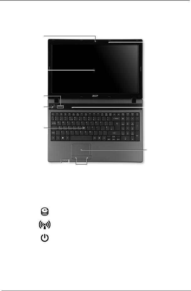
Your Acer Notebook tour
Front View
1
|
|
|
10 |
|
2 |
|
|
|
3 |
|
|
|
4 |
|
9 |
|
5 |
|
|
|
|
|
8 |
|
6 |
|
7 |
|
|
|
|
No. |
Icon |
Item |
Description |
|
|
|
|
1 |
|
Acer Crystal Eye |
Web camera for video communication |
|
|
webcam |
(for selected models). |
|
|
|
|
2 |
|
Display screen |
Also called Liquid-Crystal Display (LCD), |
|
|
|
displays computer output. |
|
|
|
|
3 |
|
HDD |
Indicates when the hard disk drive is active. |
|
|
|
|
|
|
Communication |
Indicates the computer’s wireless connectivity |
|
|
indicator |
device status. |
|
|
|
|
4 |
|
Power button |
Turns the computer on and off. |
|
|
|
|
5 |
|
Keyboard |
For entering data into your computer. |
|
|
|
|
6 |
|
Touchpad |
Touch-sensitive pointing device which functions |
|
|
|
like a computer mouse. |
|
|
|
|
8 |
Chapter 1 |
No. |
Icon |
Item |
Description |
|
|
|
|
7 |
|
Power |
Indicates the computer’s power status. |
|
|
|
|
|
|
Battery |
Indicates the computer’s battery status. |
|
|
|
1. Charging: The light shows amber when the |
|
|
|
battery is charging. |
|
|
|
2. Fully charged: The light shows blue when in |
|
|
|
AC mode. |
|
|
|
|
8 |
|
Click buttons (left |
The left and right buttons function like the left |
|
|
and right) |
and right mouse buttons. |
|
|
|
|
9 |
|
Palmrest |
Comfortable support area for your hands when |
|
|
|
you use the computer. |
|
|
|
|
10 |
|
Speakers |
Left and right speakers deliver stereo audio |
|
|
|
output. |
|
|
|
|
11 |
|
Microphone |
Internal microphone for recording sound. |
|
|
|
|
|
|
2-in-1 card |
Accepts Secure Digital (SD), MultiMediaCard |
|
|
reader |
(MMC). |
|
|
|
Note: Push to remove/install the card. Only |
|
|
|
one card can operate at any given time. |
|
|
|
|
NOTE: The 2-in1 card reader will be on the front left for UMA models and on the front right for discrete models.
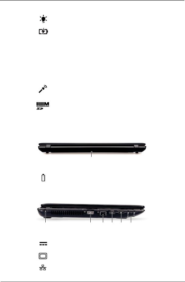
Rear View
|
|
|
1 |
|
|
|
|
|
|
No. |
Icon |
Item |
|
Description |
|
|
|
|
|
1 |
|
Battery bay |
|
Houses the computer's battery pack. |
|
|
|
|
|
Left View
|
1 |
|
2 |
3 |
4 |
5 |
6 |
|
|
|
|
|
|
|
|
|
|
No. |
Icon |
Item |
|
|
|
|
Description |
|
|
|
|
|
|
|
|||
1 |
|
DC-in jack |
|
|
Connects to an AC adapter |
|||
|
|
|
|
|
|
|||
2 |
|
External display |
|
|
Connects to a display device |
|||
|
|
(VGA) port |
|
|
(e.g. external monitor, LCD projector). |
|||
|
|
|
|
|
|
|||
3 |
|
Ethernet (RJ-45) |
|
|
Connects to an Ethernet 10/100/1000-based |
|||
|
|
port |
|
|
network. |
|
|
|
|
|
|
|
|
|
|
|
|
Chapter 1 |
9 |
No. |
Icon |
Item |
Description |
|
|
|
|
4 |
|
HDMI |
Connect to HDMI devices |
|
|
|
|
5 |
|
USB 2.0 ports |
Connect to USB 2.0 devices (e.g. USB mouse, |
|
|
|
USB camera). |
|
|
|
|
6 |
|
Microphone-in |
Accepts input from external microphones. |
|
|
jack |
|
|
|
|
|
|
|
Headphones/ |
Connects to audio line-out devices |
|
|
speaker/line-out |
(e.g. speakers, headphones). |
|
|
jack |
|
|
|
|
|
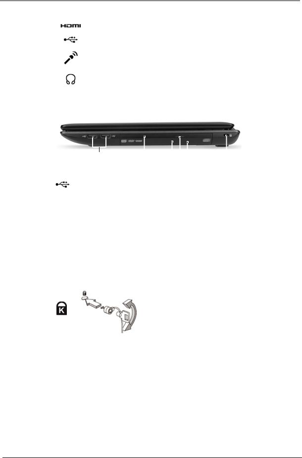
Right View
|
|
|
|
|
|
|
|
|
|
|
|
|
|
|
|
|
|
|
|
|
|
|
|
|
|
|
|
|
|
|
|
|
|
|
|
|
|
|
|
|
|
|
|
|
|
|
|
|
|
1 |
2 |
3 4 5 |
6 |
||||||
|
|
|
|
|
|
|
|
|
|
|
|
No. |
Icon |
|
|
Item |
|
|
|
|
|
Description |
|
|
|
|
|
|
|
|
|
|
|
|
|
1 |
|
USB 2.0 ports |
|
Connect to USB 2.0 devices (e.g. USB mouse, USB |
|||||||
|
|
|
|
|
|
camera). |
|
|
|||
|
|
|
|
|
|
|
|
|
|
|
|
2 |
|
Optical drive |
|
Internal optical drive; accepts CDs or DVDs. |
|||||||
|
|
|
|
|
|
|
|
|
|
|
|
3 |
|
Optical disk access |
|
Lights up when the optical drive is active. |
|||||||
|
|
indicator |
|
|
|
|
|
|
|
||
|
|
|
|
|
|
|
|
|
|
|
|
4 |
|
Optical drive eject |
|
Ejects the optical disk from the drive. |
|||||||
|
|
button |
|
|
|
|
|
|
|
||
|
|
|
|
|
|
|
|
|
|
|
|
5 |
|
Emergency eject hole |
|
Ejects the optical drive tray when the computer is |
|||||||
|
|
|
|
|
|
turned off. |
|
|
|||
|
|
|
|
|
|
Note: Insert a paper clip into the emergency eject |
|||||
|
|
|
|
|
|
hole to eject the optical drive tray when the computer |
|||||
|
|
|
|
|
|
is off. |
|
|
|||
|
|
|
|
|
|
|
|
|
|
|
|
6 |
|
Kensington lock slot |
|
Connects to a Kensington-compatible computer |
|||||||
|
|
|
|
|
|
security lock. |
|
|
|||
|
|
|
|
|
|
Note: Wrap the computer security lock cable around |
|||||
|
|
|
|
|
|
an immovable object such as a table or handle of a |
|||||
|
|
|
|
|
|
locked drawer. Insert the lock into the notch and turn |
|||||
|
|
|
|
|
|
the key to secure the lock. Some keyless models are |
|||||
|
|
|
|
|
|
also available. |
|
|
|||
|
|
|
|
|
|
|
|
|
|
|
|
10 |
Chapter 1 |
Base View
1 
2
 4
4
3
No. |
Icon |
Item |
Description |
|
|
|
|
1 |
|
Battery bay |
Houses the computer's battery pack. |
|
|
|
|
2 |
|
Battery release |
Releases the battery for removal. |
|
|
latch |
|
|
|
|
|
3 |
|
Hard disk bay |
Houses the computer's hard disk (secured |
|
|
|
with screws). |
|
|
|
|
|
|
Memory |
Houses the computer's main memory. |
|
|
compartment |
|
|
|
|
|
4 |
|
Battery lock |
Locks the battery in position. |
|
|
|
|
Indicators
The computer has several easy-to-read status indicators.
Icon |
Function |
Description |
|
|
|
|
Power |
Indicates the computer's power status. |
|
|
|
|
Battery |
Indicates the computer's battery status. |
|
|
NOTE: 1. Charging: The light shows amber when |
|
|
the battery is charging. 2. Fully charged: The light |
|
|
shows green when in AC mode. |
|
HDD |
Indicates when the hard disk drive is active. |
|
|
|
|
Communication indicator |
Indicates the computer’s wireless connectivity |
|
|
device status. |
|
|
|
Chapter 1 |
11 |
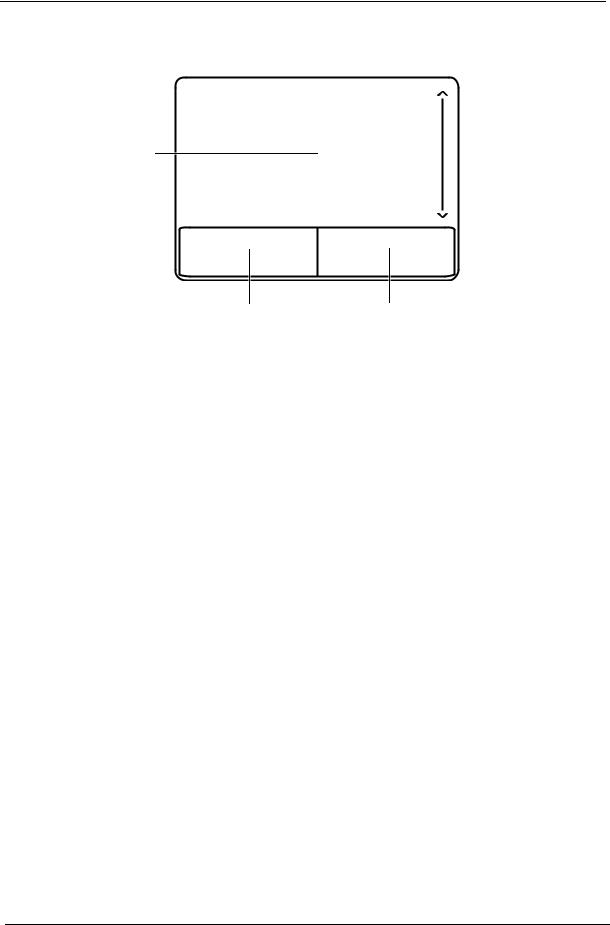
Touchpad Basics
The following items show you how to use the Touchpad:
1
2 3
•Move your finger across the Touchpad (1) to move the cursor.
•Press the left (2) and right (3) buttons located beneath the Touchpad to perform selection and execution functions. These two buttons are similar to the left and right buttons on a mouse. Tapping on the Touchpad is the same as clicking the left button.
Function |
Left Button (2) |
Right Button (3) |
Main Touchpad (1) |
|
|
|
|
Execute |
Quickly click twice. |
|
Tap twice (at the same speed |
|
|
|
as double-clicking a mouse |
|
|
|
button). |
|
|
|
|
Select |
Click once. |
|
Tap once. |
|
|
|
|
Drag |
Click and hold, then use |
|
Tap twice (at the same speed |
|
finger on the Touchpad to |
|
as double-clicking a mouse |
|
drag the cursor. |
|
button); rest your finger on |
|
|
|
the Touchpad on the second |
|
|
|
tap and drag the cursor. |
Access |
|
Click once. |
|
context menu |
|
|
|
|
|
|
|
NOTE: When using the Touchpad, keep it - and your fingers - dry and clean. The Touchpad is sensitive to finger movement; hence, the lighter the touch, the better the response. Tapping too hard will not increase the Touchpad’s responsiveness.
12 |
Chapter 1 |
Using the Keyboard
The keyboard has full-sized keys and an embedded numeric keypad, separate cursor, lock, Windows, function and special keys.
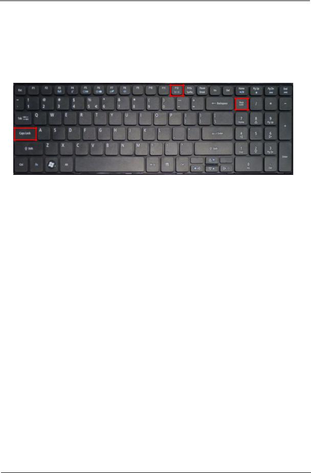
Lock Keys and embedded numeric keypad
The keyboard has two lock keys which you can toggle on and off.
Lock key |
Description |
|
|
Caps Lock |
When Caps Lock is on, all alphabetic characters typed are in uppercase. |
|
|
Scroll Lock |
When Scroll Lock is on, the contents of a text window scroll without moving the |
|
cursor. |
Num Lock |
When Num Lock is on, the embedded keypad is in numeric mode. |
|
|
Chapter 1 |
13 |
Windows Keys
The keyboard has two keys that perform Windows-specific functions.
|
|
|
Key |
Description |
|
|
|
|
|
|
|
|
Windows key |
Pressed alone, this key has the same effect as clicking on the Windows Start button; |
|
|
|
|
it launches the Start menu. It can also be used with other keys to provide a variety of |
|
|
|
|
functions: |
|
|
|
|
< >: Open or close the Start menu |
|
|
|
|
< > + <D>: Display the desktop |
|
|
|
|
< > + <E>: Open Windows Explore |
|
|
|
|
< > + <F>: Search for a file or folder |
|
|
|
|
< > + <G>: Cycle through Sidebar gadgets |
|
|
|
|
< > + <L>: Lock your computer (if you are connected to a network domain), or |
|
|
|
|
switch users (if you're not connected to a network domain) |
|
|
|
|
< > + <M>: Minimizes all windows |
|
|
|
|
< > + <R>: Open the Run dialog box |
|
|
|
|
< > + <T>: Cycle through programs on the taskbar |
|
|
|
|
< > + <U>: Open Ease of Access Center |
|
|
|
|
< > + <X>: Open Windows Mobility Center |
|
|
|
|
< > + <BREAK>: Display the System Properties dialog box |
|
|
|
|
< > + <SHIFT+M>: Restore minimized windows to the desktop |
|
|
|
|
< > + <TAB>: Cycle through programs on the taskbar by using Windows Flip 3-D |
|
|
|
|
< > + <SPACEBAR>: Bring all gadgets to the front and select Windows Sidebar |
|
|
|
|
<CTRL> + < > + <F>: Search for computers (if you are on a network) |
|
|
|
|
<CTRL> + < > + <TAB>: Use the arrow keys to cycle through programs on the |
|
|
|
|
taskbar by using Windows Flip 3-D |
|
|
|
|
Note: Depending on your edition of Windows 7, some shortcuts may not function as |
|
|
|
|
described. |
|
|
|
Application |
This key has the same effect as clicking the right mouse button; it opens the |
|
|
|
||
|
|
|
key |
application's context menu. |
|
|
|
||
|
|
|
|
|
14 |
Chapter 1 |

Hot Keys
The computer employs hotkeys or key combinations to access most of the computer’s controls like screen brightness, volume output and the BIOS utility.
To activate hot keys, press and hold the <Fn> key before pressing the other key in the hotkey combination.
Hotkey |
Icon |
Function |
Description |
|
|
|
|
|
|
<Fn> + <F3> |
|
Communication key |
Enables / disables the computer's |
|
|
|
|
|
communication devices. (Communication |
|
|
|
|
devices may vary by configuration.) |
|
|
|
|
|
<Fn> + <F4> |
|
Sleep |
Puts the computer in Sleep mode. |
|
|
|
|
|
|
<Fn> + <F5> |
|
Display toggle |
Switches display output between the display |
|
|
|
|
|
screen, external monitor (if connected) and |
|
|
|
|
both. |
|
|
|
|
|
<Fn> + <F6> |
|
Display Off |
Turns the display screen backlight off to save |
|
|
|
|
|
power. Press any key to return. |
|
|
|
|
|
<Fn> + <F7> |
|
Touchpad toggle |
Turns the internal touchpad on and off. |
|
|
|
|
|
|
<Fn> + <F8> |
|
Speaker toggle |
Turns the speakers on and off. |
|
|
|
|
|
|
<Fn> + < |
> |
|
Brightness up |
Increases the screen brightness. |
|
|
|
||
|
|
|
|
|
<Fn> + < |
> |
|
Brightness down |
Decreases the screen brightness. |
|
|
|
||
|
|
|
|
|
<Fn> + < |
> |
|
Volume up |
Increases the sound volume. |
|
|
|
||
|
|
|
|
|
<Fn> + < |
> |
|
Volume down |
Decreases the sound volume. |
|
|
|
||
|
|
|
|
|
<Fn> + <Home> |
|
Play/Pause |
Play or pause a selected media file. |
|
|
|
|
|
|
<Fn> + <Pg Up> |
|
Stop |
Stop playing the selected media file. |
|
|
|
|
|
|
<Fn> + <Pg Dn> |
|
Previous |
Return to the previous media file. |
|
|
|
|
|
|
<Fn> + <End> |
|
Next |
Jump to the next media file. |
|
|
|
|
|
|
Chapter 1 |
15 |

Hardware Specifications and Configurations
Processor
Item |
|
|
|
|
|
|
|
Specification |
|
|
||||
|
|
|
|
Discrete |
|
|
|
|
|
UMA |
|
|||
|
|
|
|
|
|
|
|
|
|
|
|
|||
|
|
|
|
|
|
|
|
|
|
|
|
|
|
|
CPU type |
|
|
AMD Family 10h Champlain Processor |
|
AMD Family 10h Champlain Processor |
|||||||||
|
|
|
|
S1g4 Socket |
|
|
|
|
|
S1g4 Socket |
|
|
||
|
|
|
|
|
|
|
|
|
|
|
|
|
|
|
CPU |
|
|
uPGA-638 Package |
|
|
|
uPGA-638 Package |
|
||||||
package |
|
|
|
|
|
|
|
|
|
|
|
|
|
|
|
|
|
|
|
|
|
|
|
|
|
|
|||
Core Logic |
|
• |
AMD RS880M North Bridge uFCBGA-528p |
|
|
|||||||||
|
|
|
|
• AMD SB820M South Bridge uFCBGA-605p |
|
|
||||||||
|
|
|
|
|
|
|
|
|
|
|
|
|
||
Processor Specifications |
|
|
|
|
|
|
|
|
|
|||||
|
|
|
|
|
|
|
|
|
|
|
|
|
|
|
|
|
CPU |
|
Bus |
|
Mfg |
Cache |
|
|
Core |
|
|||
Item |
|
Speed |
Cores |
Speed |
|
|
Package |
Acer PN |
||||||
|
|
Tech |
Size |
|
Voltage |
|||||||||
|
|
(MHz) |
|
(MT/s) |
|
|
|
|
||||||
|
|
|
|
|
|
|
|
|
|
|
||||
|
|
|
|
|
|
|
|
|
|
|
|
|
||
V140 |
|
1600 |
|
1 |
3200 |
|
45nm |
512KB |
|
uPGA- |
0.8125- |
KC.V0002.140 |
||
|
|
|
|
|
|
|
|
|
|
|
|
638 |
1.3125 |
|
|
|
|
|
|
|
|
|
|
|
|
|
|
||
P340 |
|
2200 |
|
2 |
3200 |
|
45nm |
512KB*2 |
|
uPGA- |
0.8000- |
KC.AP002.340 |
||
|
|
|
|
|
|
|
|
|
|
|
|
638 |
1.2000 |
|
|
|
|
|
|
|
|
|
|
|
|
|
|
||
N350 |
|
2400 |
|
2 |
3200 |
|
45nm |
512KB*2 |
|
uPGA- |
0.8000- |
KC.AP002.350 |
||
|
|
|
|
|
|
|
|
|
|
|
|
638 |
1.3125 |
|
|
|
|
|
|
|
|
|
|
|
|
|
|
||
P540 |
|
2400 |
|
2 |
3600 |
|
45nm |
1024KB*2 |
|
uPGA- |
0.7750- |
KC.TP002.540 |
||
|
|
|
|
|
|
|
|
|
|
|
|
638 |
1.1875 |
|
|
|
|
|
|
|
|
|
|
|
|
|
|
||
P840 |
|
1900 |
|
3 |
3600 |
|
45nm |
512KB*3 |
|
uPGA- |
0.7875- |
KC.PP002.840 |
||
|
|
|
|
|
|
|
|
|
|
|
|
638 |
1.0500 |
|
|
|
|
|
|
|
|
|
|
|
|
|
|
||
N850 |
|
2200 |
|
3 |
3600 |
|
45nm |
512KB*3 |
|
uPGA- |
0.7875- |
KC.PN002.850 |
||
|
|
|
|
|
|
|
|
|
|
|
|
638 |
1.1500 |
|
|
|
|
|
|
|
|
|
|
|
|
|
|
||
P940 |
|
1700 |
|
4 |
3600 |
|
45nm |
512KB*4 |
|
uPGA- |
0.7875- |
KC.PP002.940 |
||
|
|
|
|
|
|
|
|
|
|
|
|
638 |
1.0125 |
|
|
|
|
|
|
|
|
|
|
|
|
|
|
||
N950 |
|
2100 |
|
4 |
3600 |
|
45nm |
512KB*4 |
|
uPGA- |
0.7875- |
KC.PN002.950 |
||
|
|
|
|
|
|
|
|
|
|
|
|
638 |
1.0875 |
|
|
|
|
|
|
|
|
|
|
|
|
|
|
|
|
16 |
Chapter 1 |

Northbridge
Item |
|
Specification |
|
|
|
Chipset |
AMD RS880M |
|
Package |
uFCBGA-528p |
|
|
|
|
Features |
• |
CPU HyperTransport™ Interface |
|
• Caspian-series processors. |
|
|
• |
ATI HyperMemory |
|
• |
PCI ExpressR Interface |
|
• A-Link Express II Interface |
|
|
• Northbridge-Southbridge messaging functionalities |
|
|
• |
2D Acceleration |
|
• |
3D Acceleration |
|
• |
Motion Video Acceleration |
|
• |
Multiple Display |
|
• |
System Clocks |
|
• PC Design Guide Compliance |
|
|
|
|
Southbridge |
|
|
|
|
|
Item |
|
Specification |
|
|
|
Chipset |
AMD SB820M |
|
Package |
uFCBGA-605 |
|
|
|
|
Features |
Processor Interface |
|
|
A-Link Express II interface to Northbridges |
|
|
PCI ExpressR Controller |
|
|
PCI Host Bus Controller |
|
|
USB Controllers |
|
|
Supports port disable with individual control |
|
|
SMBus Controller |
|
|
Interrupt Controller |
|
|
DMA Controller |
|
|
LPC host bus Controller |
|
|
SATA Controller |
|
|
IDE emulation mode |
|
|
AMD RAID Support |
|
|
AHCI Support |
|
|
High Definition Audio |
|
|
Supports up to 4 codecs |
|
|
Gigabit Ethernet Media Access |
|
|
Controller (GbE MAC) |
|
|
Timers |
|
|
Real Time Clock (RTC) |
|
|
Power Management |
|
|
Consumer IR |
|
|
Hardware Monitoring |
|
|
Integrated Clock Function |
|
|
|
|
Chapter 1 |
17 |

CPU Fan True Value Table (TJ100) (Discrete Model)
CPU Temperature |
|
Fan Speed (RPM) |
SPL Spec (dBA) |
|
Core |
|
|
||
|
|
|
|
|
|
|
|
|
|
50 |
|
|
2500 |
28 |
56 |
|
|
2900 |
31 |
|
|
|
|
|
63 |
|
|
3200 |
34 |
|
|
|
|
|
70 |
|
|
3600 |
37 |
|
|
|
|
|
80 |
|
|
4000 |
40 |
|
|
|
|
|
95 |
|
|
4000 |
40 |
|
|
|
|
|
Throttling 50%: On= 95°C; OFF=85°C |
|
|||
OS shut down at 100°C; H/W shut down at 92°C |
|
|||
CPU Fan True Value Table (TJ100) (UMA Model) |
|
|||
|
|
|
|
|
CPU Temperature |
|
Fan Speed (RPM) |
SPL Spec (dBA) |
|
Core |
|
|
||
|
|
|
|
|
|
|
|
|
|
50 |
|
|
2500 |
28 |
56 |
|
|
2900 |
31 |
|
|
|
|
|
63 |
|
|
3200 |
34 |
|
|
|
|
|
70 |
|
|
3600 |
37 |
|
|
|
|
|
80 |
|
|
4000 |
40 |
|
|
|
|
|
95 |
|
|
4000 |
40 |
|
|
|
|
|
Throttling 50%: On= 95°C; OFF=85°C |
|
|||
OS shut down at 100°C; H/W shut down at 92°C |
|
|||
BIOS |
|
|
|
|
|
|
|
|
|
Item |
|
|
Specification |
|
|
|
|
||
BIOS vendor |
Insyde BIOS |
|
||
|
|
|
||
BIOS Version |
Flash |
|
||
|
|
|
||
BIOS ROM type |
16 Mbit (2MB) |
|
||
|
|
|
||
BIOS ROM size |
2MB |
|
||
|
|
|
||
Features |
• |
16Mbit(2MB) CMOS Serial Flash ROM |
||
|
• |
Support Acer UI |
|
|
|
• |
Support multi-boot |
|
|
|
• |
Suspend to RAM (S3)/Disk (S4) |
|
|
|
• |
Various hot-keys for system control |
|
|
|
• |
Support SMBIOS 2.3, PCI2.2. |
|
|
|
• |
Refer to Acer BIOS specification. |
|
|
|
• |
DMI utility for BIOS serial number configurable/asset tag |
||
|
• |
Support PXE |
|
|
|
• |
Support Y2K solution |
|
|
|
• |
Support WinFlash |
|
|
|
• |
Wake on LAN from S3 |
|
|
|
• |
Wake on LAN form S4 in AC mode |
|
|
|
• |
System information |
|
|
|
|
|
|
|
18 |
Chapter 1 |

System Memory
Item |
|
Specification |
|
|
|
|
|
Memory controller |
|
AMD DDRIII Memory controller |
|
Memory size |
|
Up to 8GB maximum |
|
|
|
|
|
DIMM socket number |
|
2 |
|
|
|
|
|
Supports memory size per socket |
|
512MB/1GB/2GB/4GB |
|
|
|
|
|
Supports maximum memory size |
|
Up to 8GB |
|
|
|
|
|
Supports DIMM type |
|
DDRIII SO-DIMM |
|
|
|
|
|
Supports DIMM Speed |
|
Up to 1333M/Ts |
|
|
|
|
|
Support DIMM voltage |
|
1.5V |
|
|
|
|
|
Supports DIMM package |
|
204-pin DDRIII SO-DIMM |
|
|
|
|
|
Memory Combinations |
|
|
|
|
|
|
|
Slot 1 |
|
Slot 2 |
Total Memory |
|
|
|
|
0MB |
1024MB |
1024MB |
|
|
|
|
|
0MB |
2048MB |
2048MB |
|
|
|
|
|
0MB |
4096MB |
4096MB |
|
|
|
|
|
1024MB |
0MB |
1024MB |
|
|
|
|
|
1024MB |
1024MB |
2048MB |
|
|
|
|
|
1024MB |
2048MB |
3072MB |
|
|
|
|
|
2048MB |
0MB |
2048MB |
|
|
|
|
|
2048MB |
1024MB |
3072MB |
|
|
|
|
|
2048MB |
2048MB |
4096MB |
|
|
|
|
|
2048MB |
4096MB |
6144MB |
|
|
|
|
|
4096MB |
4096MB |
8192MB |
|
|
|
|
|
NOTE: Above table lists some system memory configurations. You may combine DIMMs with various capacities to form other combinations. In the above table, the configuration of slot 1 and slot 2 could be reversed.
LAN Interface
Item |
|
Specification |
|
|
|
LAN Chipset |
Broadcom 57780KMLG |
|
|
|
|
Support LAN protocol |
IEEE 802.3 / 802.3u / 802.3ab / 802.1p |
|
|
|
|
LAN connector type |
RJ-45 |
|
|
|
|
LAN connector location |
Left side |
|
|
|
|
Features |
• |
Integrated 10/100/10000BASE-T transceiver |
|
• |
Automatic MDI crossover function |
|
• |
PCIe V1.1 compliant |
|
• |
10/100/10000BASE-T full -duplex/half -duplex MAC |
|
• |
Receive side scaling(RSS) for multicore processors |
|
• |
Complies with IEEE 802.3, 802.3u, 802.3ab, and 802.1p |
|
• |
Wake on LAN (WOL) support meeting the ACPI requirements |
|
• |
Statistics for SNMP MIB II, Ethernet-like MIB, and Ethernet MIB (IEEE 802.3z, |
|
|
Clause 30) |
|
• |
Self-boot feature, utilizing smaller EEPROM size with ability to use on-chip |
|
|
memory |
|
• |
Supports iSCSI boot |
|
• |
PCI Express CLKREQ support |
|
• |
Integrated switching regulator for improved power consumption |
|
• |
IPv4 and IPv6 large send off load and checksum off load (LSO/TCO) |
|
|
|
Chapter 1 |
19 |

Wireless Module 802.11b/g/n
Item |
|
|
|
Specification |
|
|
||
|
|
|
|
|
|
|
|
|
Chipset |
|
Atheros HB93/HB95/ HB97, Broadcom 943225/43225/ 4313/ 4312, RTL8192 |
|
|||||
Data throughput |
|
11~54 Mbps, up to 270 Mbps for Draft-N |
|
|
||||
|
|
|
|
|
|
|
|
|
Protocol |
|
802.11 b+g, Draft-N |
|
|
|
|
|
|
|
|
|
|
|
|
|
|
|
Interface |
|
PCI bus (mini PCI socket for wireless module) |
|
|
||||
|
|
|
|
|
|
|
|
|
Bluetooth Interface |
|
|
|
|
|
|
|
|
|
|
|
|
|
|
|
|
|
Item |
|
|
|
Specification |
|
|
||
|
|
|
|
|
|
|
|
|
Chipset |
|
Atheros AR3011/ Broadcom BCM2070/ Broadcom BCM2046 |
|
|
||||
|
|
|
|
|
|
|
|
|
Data throughput |
|
TX 1.2Mbits/sec |
|
|
|
|
|
|
|
|
RX 1.2Mbits/sec |
|
|
|
|
|
|
|
|
|
|
|
|
|
|
|
Protocol |
|
3.0+HS |
|
|
|
|
|
|
|
|
|
|
|
|
|
|
|
Interface |
|
USB 2.0 |
|
|
|
|
|
|
|
|
|
|
|
|
|
|
|
Connector type |
|
SM08B-SURS-TF/JST SM06B-XSRK-ETB/SM08B-SURS-TF |
|
|
||||
|
|
|
|
|
|
|
|
|
3G (Not available in this model) |
|
|
|
|
|
|||
|
|
|
|
|
|
|
|
|
Item |
|
|
|
|
Specification |
|
|
|
|
|
|
|
|
|
|
|
|
|
|
|
|
|
|
|
|
|
Hard Disk Drive Interface |
|
|
|
|
|
|||
|
|
|
|
|
|
|
|
|
Item |
|
|
|
Specification |
|
|
||
|
|
|
|
|
|
|
||
Vendor & Model |
|
WD1600BEVT- |
WD2500BEVT- |
|
WD3200BEVT- |
WD5000BEVT- |
||
Name |
|
22A23T0, |
22A23T0, |
|
22A23T0, |
22A0RT0, |
||
|
|
HTS545016B9A |
HTS545025B9A |
|
HTS545032B9A |
HTS545050B9A |
||
|
|
300, |
|
300, |
|
300, |
300, |
|
|
|
MK1665GSX, |
MK2565GSX, |
|
MK3265GSX, |
MK5065GSX, |
||
|
|
ST9160314AS |
ST9250315AS |
|
ST9320315AS |
ST9500325AS |
||
|
|
|
|
|
|
|
||
Capacity (GB) |
|
160GB |
250GB |
|
320GB |
500GB |
||
|
|
|
|
|
|
|
|
|
Bytes per sector |
|
512 |
|
|
|
|
|
|
|
|
|
|
|
|
|
|
|
Data heads |
|
1,2,1,2 |
2,2,2,2 |
|
2,3,2,3 |
4 |
|
|
|
|
|
|
|
|
|
|
|
Drive Format |
|
|
|
|
|
|
|
|
|
|
|
|
|
|
|
|
|
Disks |
|
1 |
|
1 |
|
1,2,1,2 |
2 |
|
|
|
|
|
|
|
|
|
|
Spindle speed |
|
5400RPM |
|
|
|
|
|
|
(RPM) |
|
|
|
|
|
|
|
|
|
|
|
|
|
|
|
||
Performance Specifications |
|
|
|
|
|
|||
|
|
|
|
|
|
|
|
|
Buffer size |
|
8MB |
|
|
|
|
|
|
|
|
|
|
|
|
|
|
|
Interface |
|
SATA |
|
|
|
|
|
|
|
|
|
|
|
|
|
|
|
Fast data transfer |
|
3.0Gbits/s |
|
|
|
|
|
|
rate |
|
|
|
|
|
|
|
|
|
|
|
|
|
|
|
||
Media data |
|
106Mbytes/s |
106Mbytes/s |
|
106Mbytes/s |
106Mbytes/s |
||
transfer rate |
|
845Mbits/s |
845Mbits/s |
|
845Mbits/s |
845Mbits/s |
||
|
|
1175Mbits/s |
1175Mbit/s |
|
1175Mbits/s |
1175Mbit/s |
||
|
|
1273.3Mbits/s |
1031.7Mbits/s |
|
1273.3Mbits/s |
1031.7Mbits/s |
||
|
|
|
|
|
|
|
||
DC Power Requirements |
|
|
|
|
|
|||
|
|
|
|
|
|
|
|
|
Voltage tolerance |
|
5V |
|
|
|
|
|
|
|
|
|
|
|
|
|
|
|
20 |
Chapter 1 |
Loading...