


Chapter 3
Machine Disassembly and Replacement
This chapter contains step-by-step procedures on how to disassemble the notebook for maintenance and troubleshooting. Here, we take an Aspire 5110 as sample for disassembly.
To disassemble the computer, you need the tools below:
•Wrist ground strap and conductive mat for preventing electrostatic discharge
•Small Philips screw driver
•Flat head screw driver
•Hexagonal driver
•Tweezers
NOTE: The screws for the different components vary in size. During the disassembly process, group the screws with the corresponding components to avoid mismatch when putting back the components. When you remove the stripe cover, please be careful not to scrape the cover.
Chapter 3 |
53 |

General Information
Before You Begin
Before proceeding with the disassembly procedure, you have to make sure that:
1.The system and all peripherals are powered off.
2.The AC adaptor and all power and signal cables from the system are unplugged.
3.The battery pack is removed.
NOTE: There are several types of screws used to secure the main unit. The screws vary in length. Please refer to the screws table after the flowchart. Group the same type of screws together during service disassembling. Please also remember the screw location for each screw type. If you fasten the screws on the wrong location, the long screws may cause irrecoverable damage to the main board.
54 |
Chapter 3 |
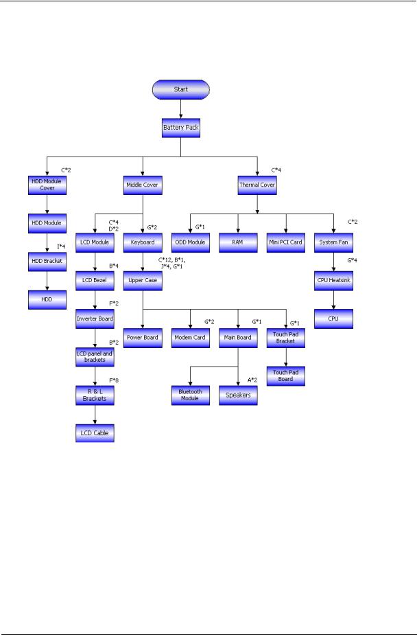
Disassembly Procedure Flowchart
The flowchart gives you a graphic representation on the entire disassembly and reassembly and instructs you how to remove the components.
Screws List
No. |
Description |
Part No. |
|
|
|
a |
SCREW M2.5*3(NL) |
86.ADWV5.001 |
|
|
|
b |
SCREW M2.5*6(NL) |
86.ADWV5.002 |
|
|
|
c |
SCREW M2.5*10(NL) |
86.ADWV5.003 |
|
|
|
d |
SCREW M2.5*15(NL) |
86.ADWV5.004 |
|
|
|
e |
SCREW M2*2.2 |
86.ADWV5.005 |
|
|
|
f |
SCREW M2*3-B (NL) |
86.ADWV5.006 |
|
|
|
g |
SCREW M2*3-S (NL) |
86.ADWV5.007 |
|
|
|
h |
SCREW M2*4 |
86.ADWV5.008 |
|
|
|
i |
SCREW M3*4 (NL) |
86.ADWV5.009 |
|
|
|
Chapter 3 |
55 |

Screws List
No. |
Description |
Part No. |
|
|
|
j |
SCREW D-SUB 4#X40*1/5-NI (NL) |
86.ADWV5.010 |
|
|
|
56 |
Chapter 3 |
Disassembly Procedure
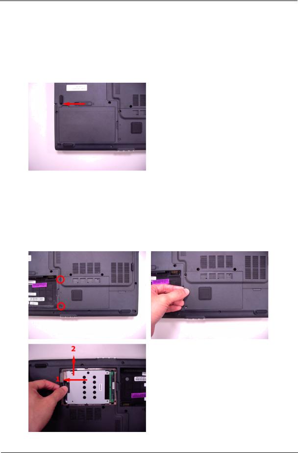
Removing the Battery Pack
1.Slide the battery lock to the end as the arrow indicates.
2.The battery pack will pop up then remove it.
Removing the HDD Module
1.Release the two screws fastening the HDD module cover.
2.Detach the HDD module cover.
3.Pull the HDD module then lift the HDD module as the arrow indicates then detach the HDD module.
Chapter 3 |
57 |

Removing the RAM Module/Mini PCI Card/Thermal Module/CPU
1.Release the four screws holding the thermal module cover.
2.Remove the thermal module cover.
3.Pull the RAM module locks at the same time as the arrows indicate.
4.The RAM module will pop up then detach it. Repeat the anterior step to remove another RAM module.
5.Pull the Mini PCI card locks at the same time as the arrows indicate.
6.The Mini PCI card will pop up then detach it.
7.Disconnect the auxiliary antenna cable (gray) and the main antenna cable (black).
58 |
Chapter 3 |
 Loading...