


ASPIRE 5334
Table of contents
 Loading...
Aspire 5334/5734Z Series
Service Guide
PRINTED IN TAIWAN
Service guide files and updates are available
on the ACER/CSD web; for more information,
please refer to http://csd.acer.com.tw

II
Revision History
Please refer to the table below for the updates made on Aspire 5334 Series service guides.
Date Chapter Updates

III
Copyright
Copyright © 2010 by Acer Incorporated. All rights reserved. No part of this publication may be reproduced,
transmitted, transcribed, stored in a retrieval system, or translated into any language or computer language, in
any form or by any means, electronic, mechanical, magnetic, optical, chemical, manual or otherwise, without
the prior written permission of Acer Incorporated.
Disclaimer
The information in this guide is subject to change without notice.
Acer Incorporated makes no representations or warranties, either expressed or implied, with respect to the
contents hereof and specifically disclaims any warranties of merchantability or fitness for any particular
purpose. Any Acer Incorporated software described in this manual is sold or licensed "as is". Should the
programs prove defective following their purchase, the buyer (and not Acer Incorporated, its distributor, or its
dealer) assumes the entire cost of all necessary servicing, repair, and any incidental or consequential
damages resulting from any defect in the software.
Acer is a registered trademark of Acer Corporation.
Intel is a registered trademark of Intel Corporation.
Other brand and product names are trademarks and/or registered trademarks of their respective holders.

IV
Conventions
The following conventions are used in this manual:
SCREEN MESSAGES Denotes actual messages that appear
on screen.
NOTE Gives bits and pieces of additional
information related to the current
topic.
WARNING Alerts you to any damage that might
result from doing or not doing specific
actions.
CAUTION Gives precautionary measures to
avoid possible hardware or software
problems.
IMPORTANT Reminds you to do specific actions
relevant to the accomplishment of
procedures.

V
Preface
Before using this information and the product it supports, please read the following general information.
1. This Service Guide provides you with all technical information relating to the BASIC CONFIGURATION
decided for Acer's "global" product offering. To better fit local market requirements and enhance product
competitiveness, your regional office MAY have decided to extend the functionality of a machine (e.g.
add-on card, modem, or extra memory capability). These LOCALIZED FEATURES will NOT be covered
in this generic service guide. In such cases, please contact your regional offices or the responsible
personnel/channel to provide you with further technical details.
2. Please note WHEN ORDERING FRU PARTS, that you should check the most up-to-date information
available on your regional web or channel. If, for whatever reason, a part number change is made, it will
not be noted in the printed Service Guide. For ACER-AUTHORIZED SERVICE PROVIDERS, your Acer
office may have a DIFFERENT part number code to those given in the FRU list of this printed Service
Guide. You MUST use the list provided by your regional Acer office to order FRU parts for repair and
service of customer machines.

VI

VII
Table of Contents
System Specifications 1
Features . . . . . . . . . . . . . . . . . . . . . . . . . . . . . . . . . . . . . . . . . . . . . . . . . . . . . . . . . . . .1
Optical Media Drive . . . . . . . . . . . . . . . . . . . . . . . . . . . . . . . . . . . . . . . . . . . . . . . .2
System Block Diagram . . . . . . . . . . . . . . . . . . . . . . . . . . . . . . . . . . . . . . . . . . . . . . . . .5
Your Acer Notebook tour . . . . . . . . . . . . . . . . . . . . . . . . . . . . . . . . . . . . . . . . . . . . . . .6
Front View . . . . . . . . . . . . . . . . . . . . . . . . . . . . . . . . . . . . . . . . . . . . . . . . . . . . . . .6
Closed Front View . . . . . . . . . . . . . . . . . . . . . . . . . . . . . . . . . . . . . . . . . . . . . . . . .7
Left View . . . . . . . . . . . . . . . . . . . . . . . . . . . . . . . . . . . . . . . . . . . . . . . . . . . . . . . .7
Right View . . . . . . . . . . . . . . . . . . . . . . . . . . . . . . . . . . . . . . . . . . . . . . . . . . . . . . .9
Bottom View . . . . . . . . . . . . . . . . . . . . . . . . . . . . . . . . . . . . . . . . . . . . . . . . . . . . .9
Indicators . . . . . . . . . . . . . . . . . . . . . . . . . . . . . . . . . . . . . . . . . . . . . . . . . . . . . .10
TouchPad Basics . . . . . . . . . . . . . . . . . . . . . . . . . . . . . . . . . . . . . . . . . . . . . . . .11
Using the Keyboard . . . . . . . . . . . . . . . . . . . . . . . . . . . . . . . . . . . . . . . . . . . . . . . . . .12
Lock Keys and embedded numeric keypad . . . . . . . . . . . . . . . . . . . . . . . . . . . .12
Windows Keys . . . . . . . . . . . . . . . . . . . . . . . . . . . . . . . . . . . . . . . . . . . . . . . . . .13
Hot Keys . . . . . . . . . . . . . . . . . . . . . . . . . . . . . . . . . . . . . . . . . . . . . . . . . . . . . . .14
Hardware Specifications and Configurations . . . . . . . . . . . . . . . . . . . . . . . . . . . . . . .15
System Utilities 23
BIOS Setup Utility . . . . . . . . . . . . . . . . . . . . . . . . . . . . . . . . . . . . . . . . . . . . . . . . . . . .23
Navigating the BIOS Utility . . . . . . . . . . . . . . . . . . . . . . . . . . . . . . . . . . . . . . . . .23
HM52-MV Intel BIOS . . . . . . . . . . . . . . . . . . . . . . . . . . . . . . . . . . . . . . . . . . . . . . . . .24
Information . . . . . . . . . . . . . . . . . . . . . . . . . . . . . . . . . . . . . . . . . . . . . . . . . . . . .24
Main . . . . . . . . . . . . . . . . . . . . . . . . . . . . . . . . . . . . . . . . . . . . . . . . . . . . . . . . . .25
Security . . . . . . . . . . . . . . . . . . . . . . . . . . . . . . . . . . . . . . . . . . . . . . . . . . . . . . . .26
Boot . . . . . . . . . . . . . . . . . . . . . . . . . . . . . . . . . . . . . . . . . . . . . . . . . . . . . . . . . . .29
Exit . . . . . . . . . . . . . . . . . . . . . . . . . . . . . . . . . . . . . . . . . . . . . . . . . . . . . . . . . . .30
BIOS Flash Utilities . . . . . . . . . . . . . . . . . . . . . . . . . . . . . . . . . . . . . . . . . . . . . . . . . . .31
DOS Flash Utility . . . . . . . . . . . . . . . . . . . . . . . . . . . . . . . . . . . . . . . . . . . . . . . . .32
WinFlash Utility . . . . . . . . . . . . . . . . . . . . . . . . . . . . . . . . . . . . . . . . . . . . . . . . . .34
Remove HDD/BIOS Password Utilities . . . . . . . . . . . . . . . . . . . . . . . . . . . . . . . . . . . .35
Machine Disassembly and Replacement 43
Disassembly Requirements . . . . . . . . . . . . . . . . . . . . . . . . . . . . . . . . . . . . . . . . . . . .43
Pre-disassembly Instructions . . . . . . . . . . . . . . . . . . . . . . . . . . . . . . . . . . . . . . .44
Disassembly Process . . . . . . . . . . . . . . . . . . . . . . . . . . . . . . . . . . . . . . . . . . . . .44
External Module Disassembly Process . . . . . . . . . . . . . . . . . . . . . . . . . . . . . . . . . . .45
External Modules Disassembly Flowchart . . . . . . . . . . . . . . . . . . . . . . . . . . . . .45
Removing the Battery Pack . . . . . . . . . . . . . . . . . . . . . . . . . . . . . . . . . . . . . . . .46
Removing the SD Dummy Card . . . . . . . . . . . . . . . . . . . . . . . . . . . . . . . . . . . . .47
Removing the Lower Covers . . . . . . . . . . . . . . . . . . . . . . . . . . . . . . . . . . . . . . . .48
Removing the Optical Drive Module . . . . . . . . . . . . . . . . . . . . . . . . . . . . . . . . . .49
Removing the DIMM Modules . . . . . . . . . . . . . . . . . . . . . . . . . . . . . . . . . . . . . . .51
Removing the WLAN Module . . . . . . . . . . . . . . . . . . . . . . . . . . . . . . . . . . . . . . .52
Removing the Hard Disk Drive Module . . . . . . . . . . . . . . . . . . . . . . . . . . . . . . . .55
Removing the Switch Cover . . . . . . . . . . . . . . . . . . . . . . . . . . . . . . . . . . . . . . . .57
Removing the Keyboard . . . . . . . . . . . . . . . . . . . . . . . . . . . . . . . . . . . . . . . . . . .58
Main Unit Disassembly Process . . . . . . . . . . . . . . . . . . . . . . . . . . . . . . . . . . . . . . . . .59
Main Unit Disassembly Flowchart . . . . . . . . . . . . . . . . . . . . . . . . . . . . . . . . . . . .59
Removing the LCD Module . . . . . . . . . . . . . . . . . . . . . . . . . . . . . . . . . . . . . . . . .60
Removing the Upper Cover . . . . . . . . . . . . . . . . . . . . . . . . . . . . . . . . . . . . . . . .65
Removing the Power Board . . . . . . . . . . . . . . . . . . . . . . . . . . . . . . . . . . . . . . . .69
Removing the Left Speaker Module . . . . . . . . . . . . . . . . . . . . . . . . . . . . . . . . . .70
Removing the TouchPad Bracket . . . . . . . . . . . . . . . . . . . . . . . . . . . . . . . . . . . .72

VIII
Table of Contents
Removing the Mainboard . . . . . . . . . . . . . . . . . . . . . . . . . . . . . . . . . . . . . . . . . .74
Removing the RTC Battery . . . . . . . . . . . . . . . . . . . . . . . . . . . . . . . . . . . . . . . . .75
Removing the Thermal Module . . . . . . . . . . . . . . . . . . . . . . . . . . . . . . . . . . . . . .76
Removing the CPU Fan . . . . . . . . . . . . . . . . . . . . . . . . . . . . . . . . . . . . . . . . . . .78
Removing the CPU . . . . . . . . . . . . . . . . . . . . . . . . . . . . . . . . . . . . . . . . . . . . . . .79
LCD Module Disassembly Process . . . . . . . . . . . . . . . . . . . . . . . . . . . . . . . . . . . . . .80
LCD Module Disassembly Flowchart . . . . . . . . . . . . . . . . . . . . . . . . . . . . . . . . .80
Removing the LCD Bezel . . . . . . . . . . . . . . . . . . . . . . . . . . . . . . . . . . . . . . . . . .81
Removing the Camera Module . . . . . . . . . . . . . . . . . . . . . . . . . . . . . . . . . . . . . .82
Removing the Inverter Board . . . . . . . . . . . . . . . . . . . . . . . . . . . . . . . . . . . . . . .83
Removing the LCD Panel . . . . . . . . . . . . . . . . . . . . . . . . . . . . . . . . . . . . . . . . . .84
Removing the LCD Brackets and FPC Cable . . . . . . . . . . . . . . . . . . . . . . . . . . .85
Removing the Antennas . . . . . . . . . . . . . . . . . . . . . . . . . . . . . . . . . . . . . . . . . . .87
LCD Module Reassembly Procedure . . . . . . . . . . . . . . . . . . . . . . . . . . . . . . . . . . . . .90
Replacing the Antennas . . . . . . . . . . . . . . . . . . . . . . . . . . . . . . . . . . . . . . . . . . .90
Replacing the LCD Panel . . . . . . . . . . . . . . . . . . . . . . . . . . . . . . . . . . . . . . . . . .93
Replacing the Camera Module . . . . . . . . . . . . . . . . . . . . . . . . . . . . . . . . . . . . . .94
Replacing the Inverter Board . . . . . . . . . . . . . . . . . . . . . . . . . . . . . . . . . . . . . . .95
Replacing the LCD Bezel . . . . . . . . . . . . . . . . . . . . . . . . . . . . . . . . . . . . . . . . . .96
Main Module Reassembly Procedure . . . . . . . . . . . . . . . . . . . . . . . . . . . . . . . . . . . . .98
Replacing the CPU . . . . . . . . . . . . . . . . . . . . . . . . . . . . . . . . . . . . . . . . . . . . . . .98
Replacing the CPU Fan . . . . . . . . . . . . . . . . . . . . . . . . . . . . . . . . . . . . . . . . . . .99
Replacing the Thermal Module . . . . . . . . . . . . . . . . . . . . . . . . . . . . . . . . . . . . . .99
Replacing the Mainboard . . . . . . . . . . . . . . . . . . . . . . . . . . . . . . . . . . . . . . . . .100
Replacing the TouchPad Bracket . . . . . . . . . . . . . . . . . . . . . . . . . . . . . . . . . . .101
Replacing the Left Speaker Module . . . . . . . . . . . . . . . . . . . . . . . . . . . . . . . . .103
Replacing the Power Board . . . . . . . . . . . . . . . . . . . . . . . . . . . . . . . . . . . . . . .103
Replacing the Upper Cover . . . . . . . . . . . . . . . . . . . . . . . . . . . . . . . . . . . . . . . .105
Replacing the LCD Module . . . . . . . . . . . . . . . . . . . . . . . . . . . . . . . . . . . . . . . .109
Replacing the Keyboard . . . . . . . . . . . . . . . . . . . . . . . . . . . . . . . . . . . . . . . . . .114
Replacing the Switch Cover . . . . . . . . . . . . . . . . . . . . . . . . . . . . . . . . . . . . . . .115
Replacing the Hard Disk Drive Module . . . . . . . . . . . . . . . . . . . . . . . . . . . . . . .115
Replacing the WLAN Module . . . . . . . . . . . . . . . . . . . . . . . . . . . . . . . . . . . . . .117
Replacing the DIMM Modules . . . . . . . . . . . . . . . . . . . . . . . . . . . . . . . . . . . . . .119
Replacing the ODD Module . . . . . . . . . . . . . . . . . . . . . . . . . . . . . . . . . . . . . . .119
Replacing the Lower Covers . . . . . . . . . . . . . . . . . . . . . . . . . . . . . . . . . . . . . . .120
Replacing the SD Dummy Card . . . . . . . . . . . . . . . . . . . . . . . . . . . . . . . . . . . .120
Replacing the Battery . . . . . . . . . . . . . . . . . . . . . . . . . . . . . . . . . . . . . . . . . . . .121
Troubleshooting 123
Common Problems . . . . . . . . . . . . . . . . . . . . . . . . . . . . . . . . . . . . . . . . . . . . . . . . . .123
Power On Issue . . . . . . . . . . . . . . . . . . . . . . . . . . . . . . . . . . . . . . . . . . . . . . . .124
No Display Issue . . . . . . . . . . . . . . . . . . . . . . . . . . . . . . . . . . . . . . . . . . . . . . . .125
Random Loss of BIOS Settings . . . . . . . . . . . . . . . . . . . . . . . . . . . . . . . . . . . .126
LCD Failure . . . . . . . . . . . . . . . . . . . . . . . . . . . . . . . . . . . . . . . . . . . . . . . . . . . .127
Built-In Keyboard Failure . . . . . . . . . . . . . . . . . . . . . . . . . . . . . . . . . . . . . . . . .127
TouchPad Failure . . . . . . . . . . . . . . . . . . . . . . . . . . . . . . . . . . . . . . . . . . . . . . .128
Internal Speaker Failure . . . . . . . . . . . . . . . . . . . . . . . . . . . . . . . . . . . . . . . . . .128
HDD Not Operating Correctly . . . . . . . . . . . . . . . . . . . . . . . . . . . . . . . . . . . . . .130
ODD Failure . . . . . . . . . . . . . . . . . . . . . . . . . . . . . . . . . . . . . . . . . . . . . . . . . . .131
Wireless Function Failure . . . . . . . . . . . . . . . . . . . . . . . . . . . . . . . . . . . . . . . . .134
Thermal Unit Failure . . . . . . . . . . . . . . . . . . . . . . . . . . . . . . . . . . . . . . . . . . . . .134
External Mouse Failure . . . . . . . . . . . . . . . . . . . . . . . . . . . . . . . . . . . . . . . . . . .135
Other Failures . . . . . . . . . . . . . . . . . . . . . . . . . . . . . . . . . . . . . . . . . . . . . . . . . .135
Intermittent Problems . . . . . . . . . . . . . . . . . . . . . . . . . . . . . . . . . . . . . . . . . . . . . . . .136

IX
Table of Contents
Undetermined Problems . . . . . . . . . . . . . . . . . . . . . . . . . . . . . . . . . . . . . . . . . . . . . .136
Post Codes . . . . . . . . . . . . . . . . . . . . . . . . . . . . . . . . . . . . . . . . . . . . . . . . . . . . . . . .137
Jumper and Connector Locations 145
Top View . . . . . . . . . . . . . . . . . . . . . . . . . . . . . . . . . . . . . . . . . . . . . . . . . . . . . .145
Bottom View . . . . . . . . . . . . . . . . . . . . . . . . . . . . . . . . . . . . . . . . . . . . . . . . . . .146
Power Board . . . . . . . . . . . . . . . . . . . . . . . . . . . . . . . . . . . . . . . . . . . . . . . . . . .147
Clearing Password Check and BIOS Recovery . . . . . . . . . . . . . . . . . . . . . . . . . . . .148
Clearing Password Check . . . . . . . . . . . . . . . . . . . . . . . . . . . . . . . . . . . . . . . . .148
Clear CMOS Jumper . . . . . . . . . . . . . . . . . . . . . . . . . . . . . . . . . . . . . . . . . . . . .149
BIOS Recovery by Crisis Disk . . . . . . . . . . . . . . . . . . . . . . . . . . . . . . . . . . . . .150
FRU (Field Replaceable Unit) List 151
JE50_MV Exploded Diagrams . . . . . . . . . . . . . . . . . . . . . . . . . . . . . . . . . . . . . . . . .152
Main Assembly . . . . . . . . . . . . . . . . . . . . . . . . . . . . . . . . . . . . . . . . . . . . . . . . .152
Rear Assembly . . . . . . . . . . . . . . . . . . . . . . . . . . . . . . . . . . . . . . . . . . . . . . . . .153
LCD Assembly . . . . . . . . . . . . . . . . . . . . . . . . . . . . . . . . . . . . . . . . . . . . . . . . .154
JE50_MV FRU List . . . . . . . . . . . . . . . . . . . . . . . . . . . . . . . . . . . . . . . . . . . . . . . . . .155
Screw List . . . . . . . . . . . . . . . . . . . . . . . . . . . . . . . . . . . . . . . . . . . . . . . . . . . . . . . . .163
Model Definition and Configuration 164
Test Compatible Components 219
Microsoft® Windows® 7 Environment Test . . . . . . . . . . . . . . . . . . . . . . . . . . . . . . .220
Online Support Information 233
Index 235

X
Table of Contents

Chapter 1 1
System Specifications
Features
Below is a brief summary of the computer’s many features:
NOTE: Items denoted with an (*) are only available for selected models.
Operating System
• Genuine Windows® 7 Home Premium 64-bit
• Genuine Windows® 7 Home Basic 64-b i t
Platform
Aspire 5334
• Intel® Celeron® processor T3100/T3000 (1 MB L2 cache, 1.80/1.90 GHz, 800 MHz FSB, 35 W),
T1600/T1700 (1 MB L2 cache, 1.66/1.83 GHz, 667 MHz FSB, 35 W), supporting Intel® 64
architecture
• Intel® Celeron® processor 900 (1 MB L2 cache, 2.20 GHz, 800 MHz FSB, 35 W), supporting
Intel® 64 architecture
• Mobile Intel® GL40 Express Chipset
Aspire 5734Z
• Intel® Pentium® processor T4200/T4300/T4400/T4500 (1 MB L2 cache, 2/2.10/2.20/2.30 GHz,
800 MHz FSB, 35 W), supporting Intel® 64 architecture
• Mobile Intel® GL40 Express Chipset
System Memory
• Dual-channel DDR3 SDRAM support:
• Up to 2 GB of DDR3 system memory, upgradable to 4 GB using two soDIMM modules
Display
• 15.6” WXGA, HD 720p, 1366x768
• 16:9 aspect ratio
Graphics
• Mobile Intel® GL40 Express Chipset with integrated 3D graphics, featuring Intel® Graphics Media
Accelerator 4500M (Intel® GMA 4500M) with up to 1759 MB of Intel® Dynamic Video Memory
Technology 5.0 (64 MB of dedicated system memory, up to 1695 MB of shared system memory),
supporting Microsoft® DirectX® 10
• Dual independent display support
• 16.7 million colors
• External resolution / refresh rates:
• VGA port up to 2560 x 1600: 60 Hz
• MPEG-2/DVD decoding
• WMV9 (VC-1) and H.264 (AVC) decoding
Chapter 1

2 Chapter 1
Audio
• One built-in mono speaker
• Built-in microphone
• MS-Sound compatible
Storage subsystem
Aspire 5334/5734Z
• Hard disk drive: 160/250/320/500/640 GB or larger
Aspire 5734Z
• Multi-in-1 card reader, supporting Secure Digital™ (SD), MultiMediaCard (MMC), Memory Stick™
(MS), Memory Stick PRO™ (MS PRO), xD-Picture Card™ (xD)
Optical Media Drive
• 8X DVD-Super Multi double-layer drive:
• Read: 24X CD-ROM, 24X CD-R, 24X CD-RW, 8X DVD-ROM, 8X DVD-R, 8X DVD+R, 6X
DVD-ROM DL, 6X DVD-R DL, 6X DVD+R DL, 6X DVD-RW, 6X DVD+RW, 5X DVD-RAM
• Write: 24X CD-R, 16X CD-RW, 8X DVD-R, 8X DVD+R, 4X DVD-R DL, 4X DVD+R DL, 6X
DVD-RW, 8X DVD+RW, 5X DVD-RAM
Dimensions and Weight
• 372.3 (W) x 246.5 (D) x 26.8/39.6 (H) mm (14.51 x 9.61 x 1.04/1.54 inches)
• 2.7 kg (6.0 lbs.) with 6-cell battery pack
Communication
Webcam
• Acer Crystal Eye webcam with 1280 x 1024 resolution
• Microphone
WLAN
• 802.11 b/g/n Wi-Fi CERTIFIED™
• 802.11 b/g Wi-Fi CERTIFIED™
LAN
• 10/100 Mbps Fast Ethernet
Privacy control
• BIOS user, supervisor, HDD passwords
• Kensington lock slot

Chapter 1 3
Power subsystem
ACPI 3.0 CPU power management standard: supports Standby and Hibernation power-saving modes
Adapter:
• 3-pin 65 W AC adapter:
• 108 (W) x 46 (D) x 29.5 (H) mm (4.25 x 1.81 x 1.16 inches)
• 225 g (0.49 lbs.) with 180 cm DC cable
Battery:
• 48.8 W 4400 mAh 6-cell Li-ion battery pack
• Battery life: 3.0 hours
• ENERGY STAR®
Special keys and controls
• 99-/100-/103-key keyboard with inverted "T" cursor layout
• Touchpad pointing device
• 8 function keys, four cursor keys, two Windows® keys, independent numeric keypad, international
language support
• Easy-launch keys: touchpad lock, communication
• Media control keys (printed on keyboard): play/pause, stop, previous, next
I/O interface
• Two USB 2.0 ports
• External display (VGA) port
• Headphone/speaker/line-out jack
• Microphone-in jack
• Ethernet (RJ-45) port
• DC-in jack for AC adapter
Aspire 5734Z
• Multi-in-1 card reader (SD™, MMC, MS, MS PRO, xD)
Software
Productivity
• Acer Backup Manager
• Acer ePower Management
• Acer eRecovery Management
• Microsoft® Office Personal 2007 (Service Pack 2) (Japan only, subject to customer request)
• Microsoft® Office Trial (Service Pack 2)
• Microsoft® Works SE 9 (Brazil, Canada, France, Germany, Poland, Russia, UK and US only)
• Microsoft® Works 9
• Microsoft® Works 8.5
• Adobe® Flash® Player 10
• Adobe® Reader® 9.1
•eSobi™
• Google Toolbar™
• Norton™ Online Backup

4 Chapter 1
Security
• McAfee® Internet Security Suite Trial
• MyWinLocker® (except China, Hong Kong)
Multimedia
• Cyberlink® PowerDVD™
• NTI Media Maker™
Gaming
• Oberon GameZone (except US, Canada, Hong Kong, Korea)
• WildTangent® (US, Canada only)
Communication and ISP
• Acer Crystal Eye
• Microsoft® Silverlight™
• Windows Live™ Essentials - Wave 3.2 (Mail, Photo Gallery, Live™ Messenger, Movie Maker ,
Writer)
• Skype™
Web links and utilities
• Acer Accessory Store (Belgium, France, Germany, Italy, Netherlands, Spain, Sweden, UK only)
• Acer Assist
• Acer Identity Card
• Acer Registration
• Acer Updater
• eBay® shortcut 2009 (Canada, France, Germany, Italy, Mexico, Spain, UK, US only)
• Netflix shortcut (US only)
Optional Items
• 1 GB / 2 GB DDR3 soDIMM module
• 3-pin 65 W AC adapter
• 6-cell Li-ion battery pack
• External USB floppy disk drive
Environment
• Temperature:
• Operating: 5 °C to 35 °C
• Non-operating: -20 °C to 65 °C
• Humidity (non-condensing):
• Operating: 20% to 80%
• Non-operating: 20% to 80%
Chapter 1 5
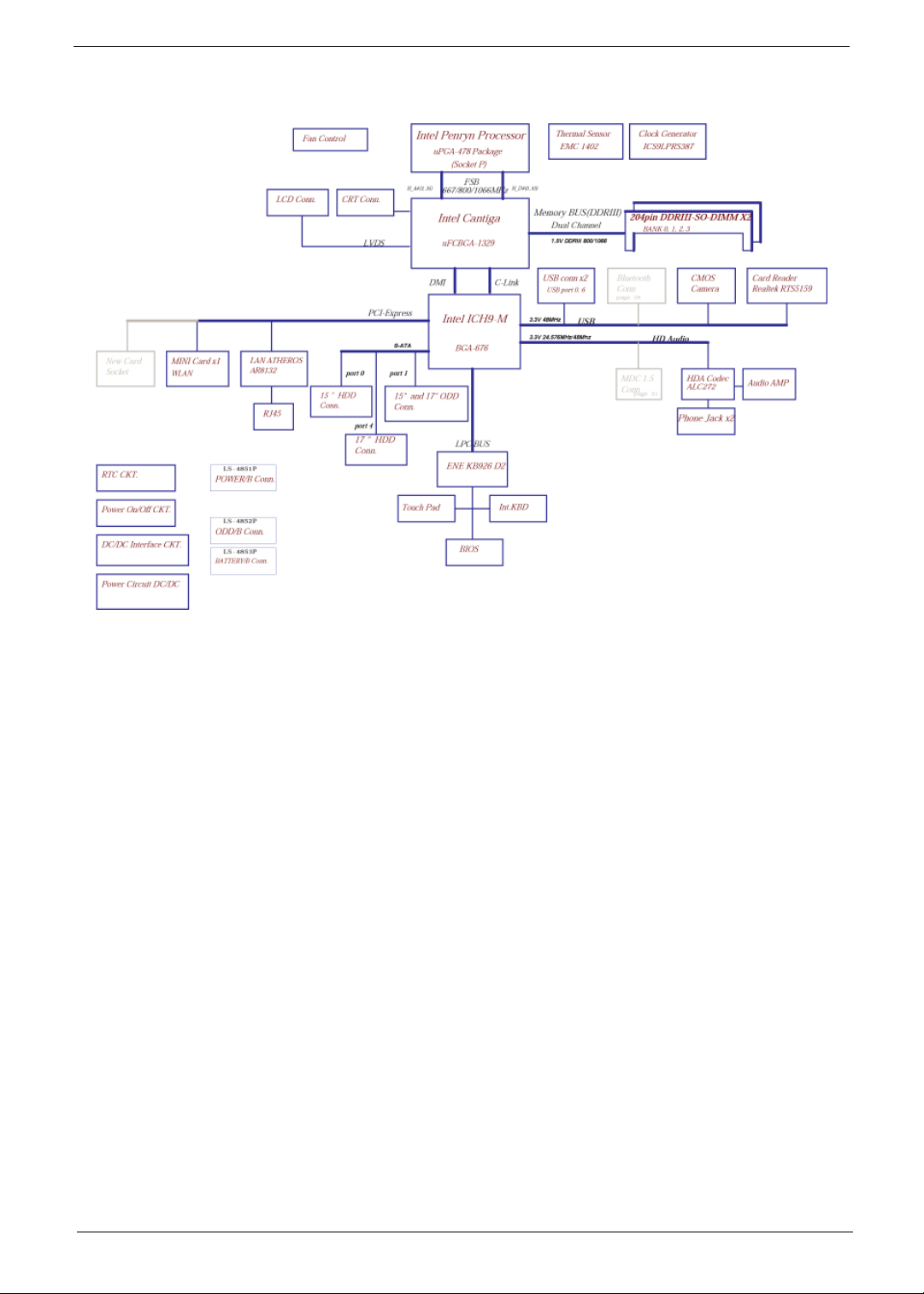
System Block Diagram
6 Chapter 1
Your Acer Notebook tour
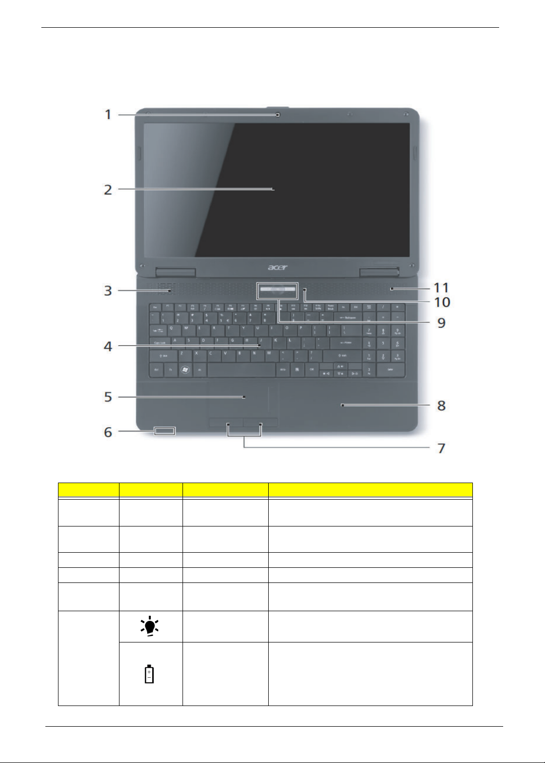
Front View
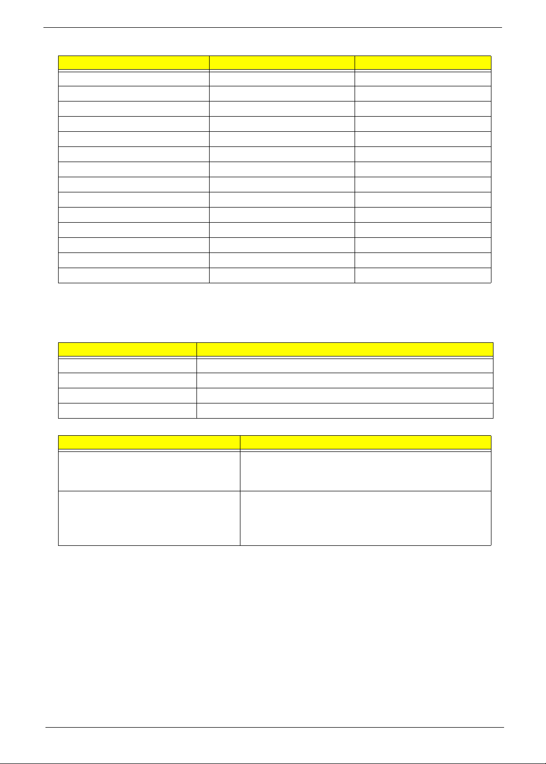
No. Icon Item Description
1 Acer Crystal Eye
webcam
Web camera for video communication
(for selected models).
2 Display screen Also called Liquid-Crystal Display (LCD),
displays computer output.
3 Speaker Delivers audio output.
4 Keyboard For entering data into your computer.
5 Touchpad Touch-sensitive pointing device which
functions like a computer mouse.
6 Power indicator Indicates the computer’s power status.
Battery indicator
Indicates the computer's battery status.
1. Charging: The light shows amber when the
battery is charging.
2. Fully charged: The light shows green when
in AC mode.
Chapter 1 7
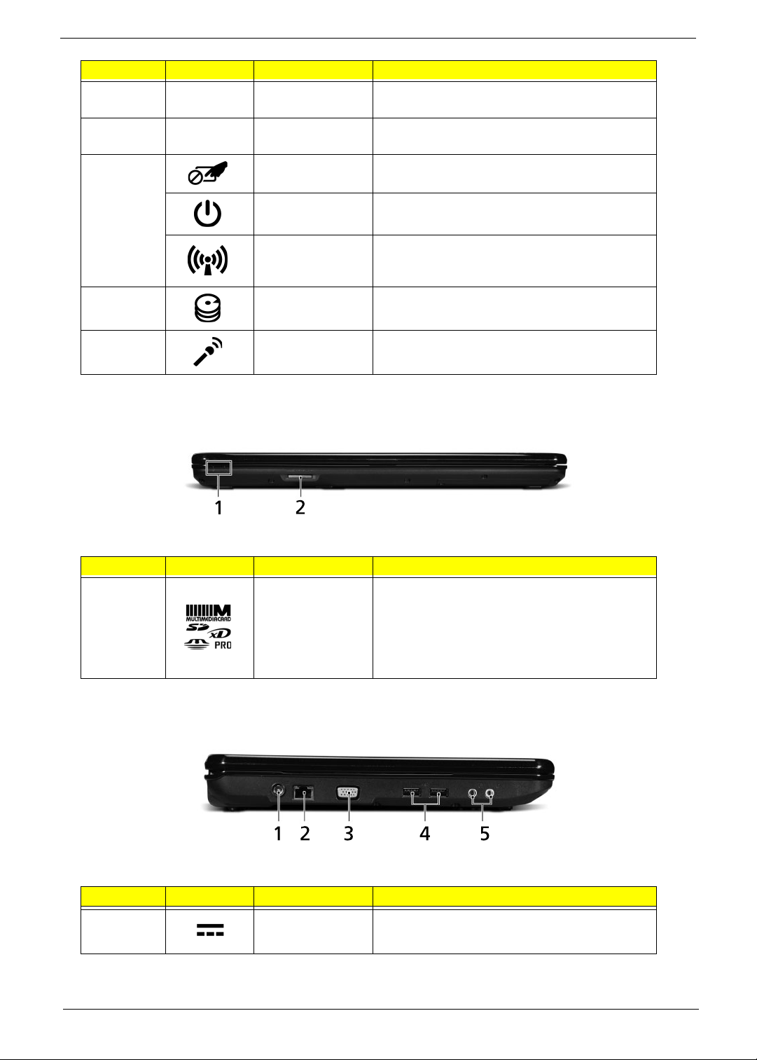
Closed Front View
Aspire 5734Z model only
Left View
7 Click buttons (left
and right)
The left and right buttons function like the left
and right mouse buttons.
8 Palmrest Comfortable support area for your hands when
you use the computer.
9 Touchpad toggle Turns the internal touchpad on and off.
Power button Turns the computer on and off.
Communication
key
Enables/disables the computer’s
communication devices. (Communication
devices may vary by configuration.)
10 HDD indicator Indicates when the hard disk drive is active.
11 Microphone Internal microphone for sound recording.
No. Icon Item Description
1 5-in-1 card
reader
Accepts Secure Digital (SD), MultiMediaCard
(MMC), Memory Stick (MS), Memory Stick
PRO (MS PRO), xDPicture Card (xD).
NOTE: Push to remove/install the card.
Only one card can operate at any
given time.
No. Icon Item Description
1 DC-in jack Connects to an AC adapter
No. Icon Item Description
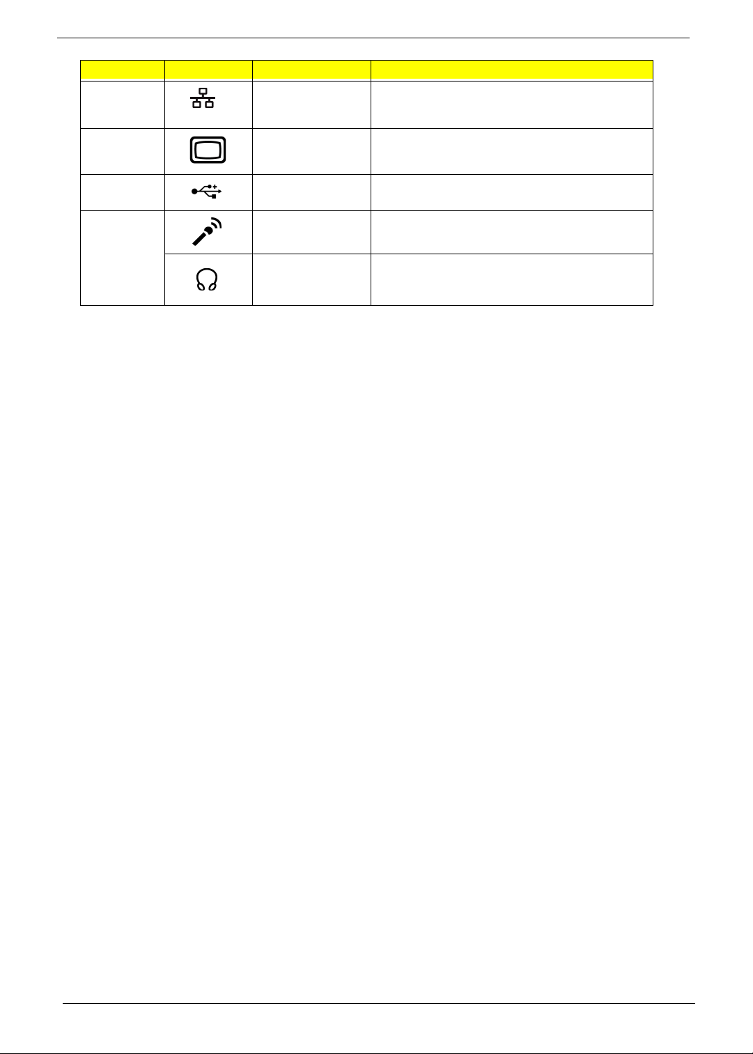
8 Chapter 1
2 Ethernet (RJ-45)
port
Connects to an Ethernet 10/100-based
network.
3 External display
(VGA) port
Connects to a display device
(e.g. external monitor, LCD projector).
4 USB 2.0 ports Connect to USB 2.0 devices (e.g. USB mouse,
USB camera).
5 Microphone-in
jack
Accepts input from external microphones.
Headphones/
speaker/line-out
jack
Connects to audio line-out devices
(e.g. speakers, headphones).
No. Icon Item Description
Chapter 1 9
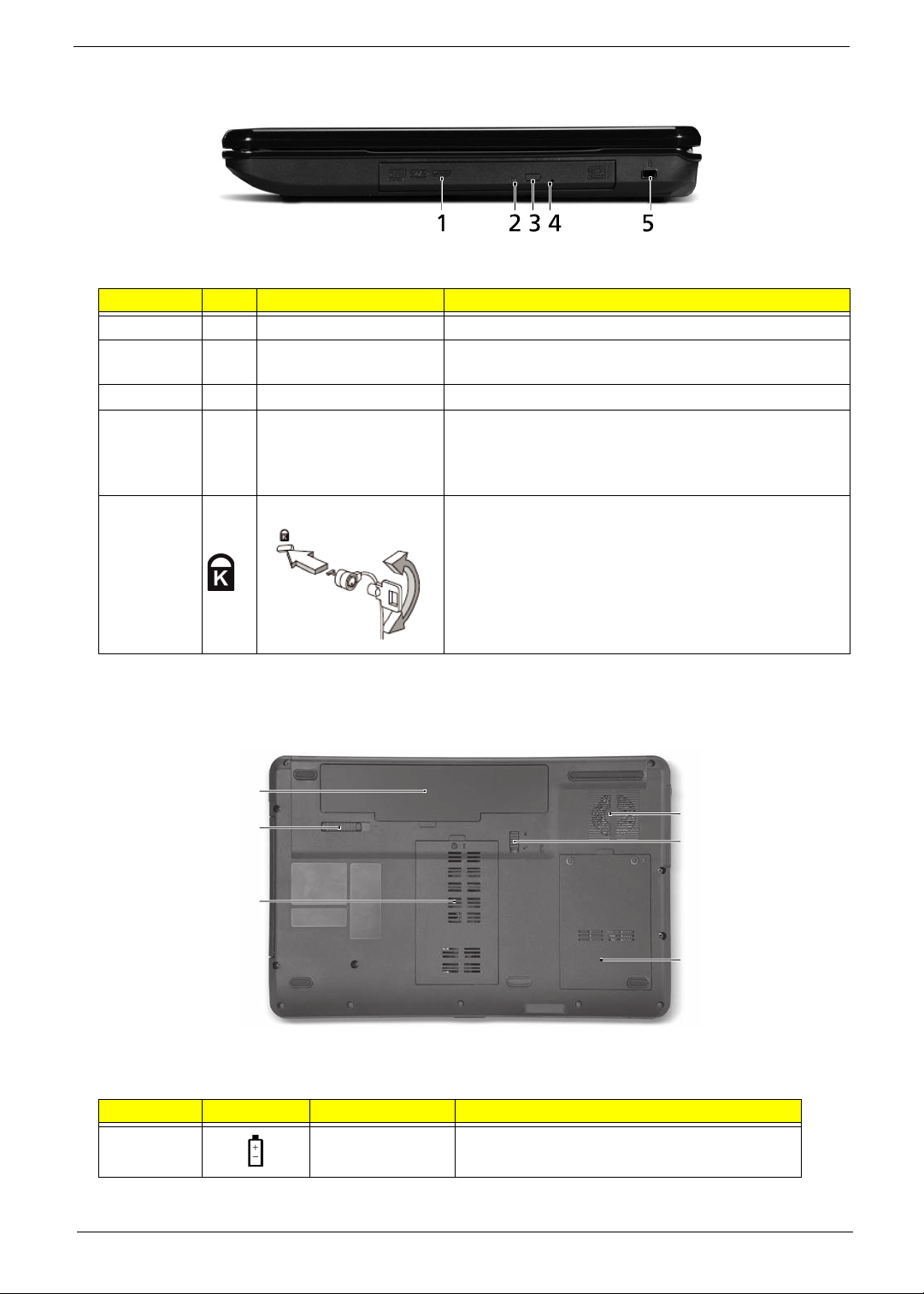
Right View
Bottom View
No. Item Description
1 Optical drive Internal optical drive; accepts CDs or DVDs.
2 Optical disk access
indicator
Lights up when the optical drive is active.
3 Optical drive eject button Ejects the optical disk from the drive.
4 Emergency eject hole Ejects the optical drive tray when the computer is turned
off.
Note: Insert a paper clip into the emergency eject hole to
eject the optical drive tray when the computer is off.
5 Kensington lock slot Connects to a Kensington-compatible computer security
lock.
Note: Wrap the computer security lock cable around an
immovable object such as a table or handle of a locked
drawer. Insert the lock into the notch and turn the key to
secure the lock. Some keyless models are also available.
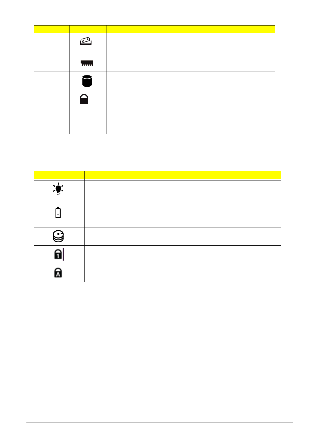
No. Icon Item Description
1 Battery bay Houses the computer's battery pack.
1
2
3
4
5
6
10 Chapter 1
Indicators
The computer has several easy-to-read status indicators. The front panel indicators are visible even when the
computer cover is closed.
2 Battery release
latch
Releases the battery for removal.
3 Memory
compartment
Houses the computer's main memory.
4 Hard disk bay Houses the computer's hard disk (secured
with screws).
5 Battery lock Locks the battery in position.
6 Ventilation slots
and cooling fan
Enable the computer to stay cool, even after
prolonged use.
Note: Do not cover or obstruct the fan opening.
Icon Function Description
Power Indicates the computer's power status.
Battery Indicates the computer's battery status.
NOTE: 1. Charging: The light shows amber when
the battery is charging. 2. Fully charged: The light
shows green when in AC mode.
HDD Indicates when the hard disk drive is active.
Num Lock Lights up when Num Lock is activated.
Caps Lock Lights up when Caps Lock is activated.
No. Icon Item Description
Chapter 1 11
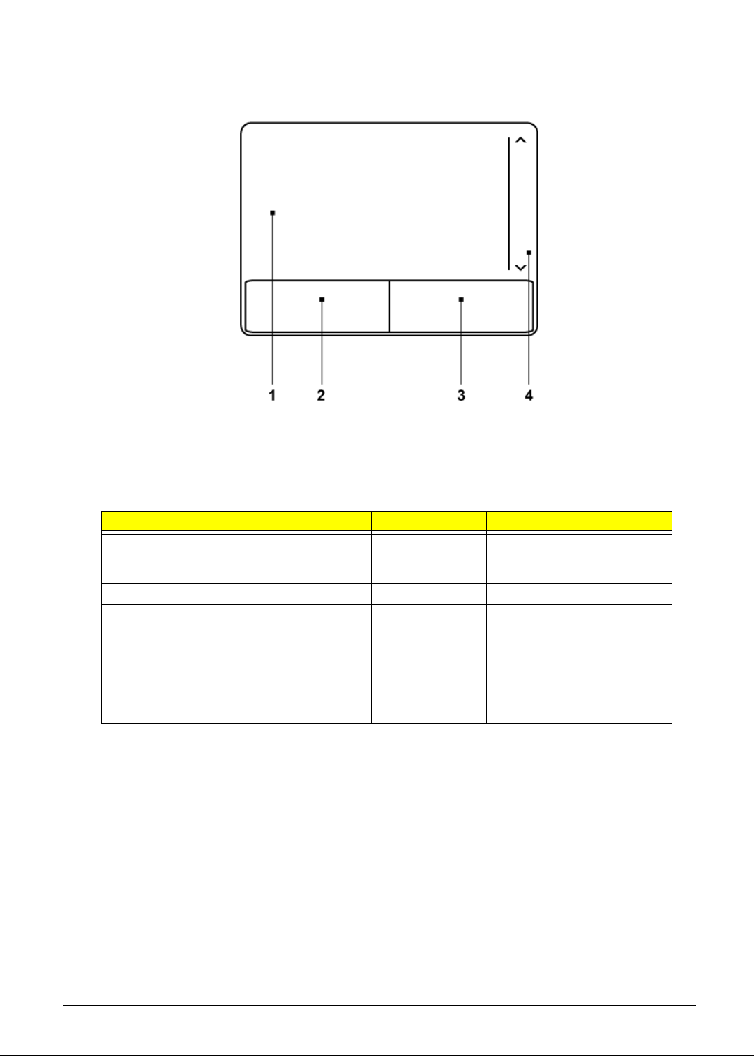
TouchPad Basics
The following items show you how to use the TouchPad:
• Move your finger across the TouchPad (1) to move the cursor.
• Press the left (2) and right (3) buttons located beneath the TouchPad to perform selection and
execution functions. These two buttons are similar to the left and right buttons on a mouse.
Tapping on the TouchPad is the same as clicking the left button.
NOTE: When using the T ouchPad, keep it - and your fingers - dry and clean. The TouchPad is sensitive to
finger movement; hence, the lighter the touch, the better the response. Tapping too hard will not
increase the TouchPad’s responsiveness.
Function Left Button (2) Right Button (3) Main TouchPad (1)
Execute Quickly click twice. Tap twice (at the same speed
as double-clicking a mouse
button).
Select Click once. Tap once.
Drag Click and hold, then use
finger on the TouchPad to
drag the cursor.
Tap twice (at the same speed
as double-clicking a mouse
button); rest your finger on
the TouchPad on the second
tap and drag the cursor.
Access
context menu
Click once.
12 Chapter 1
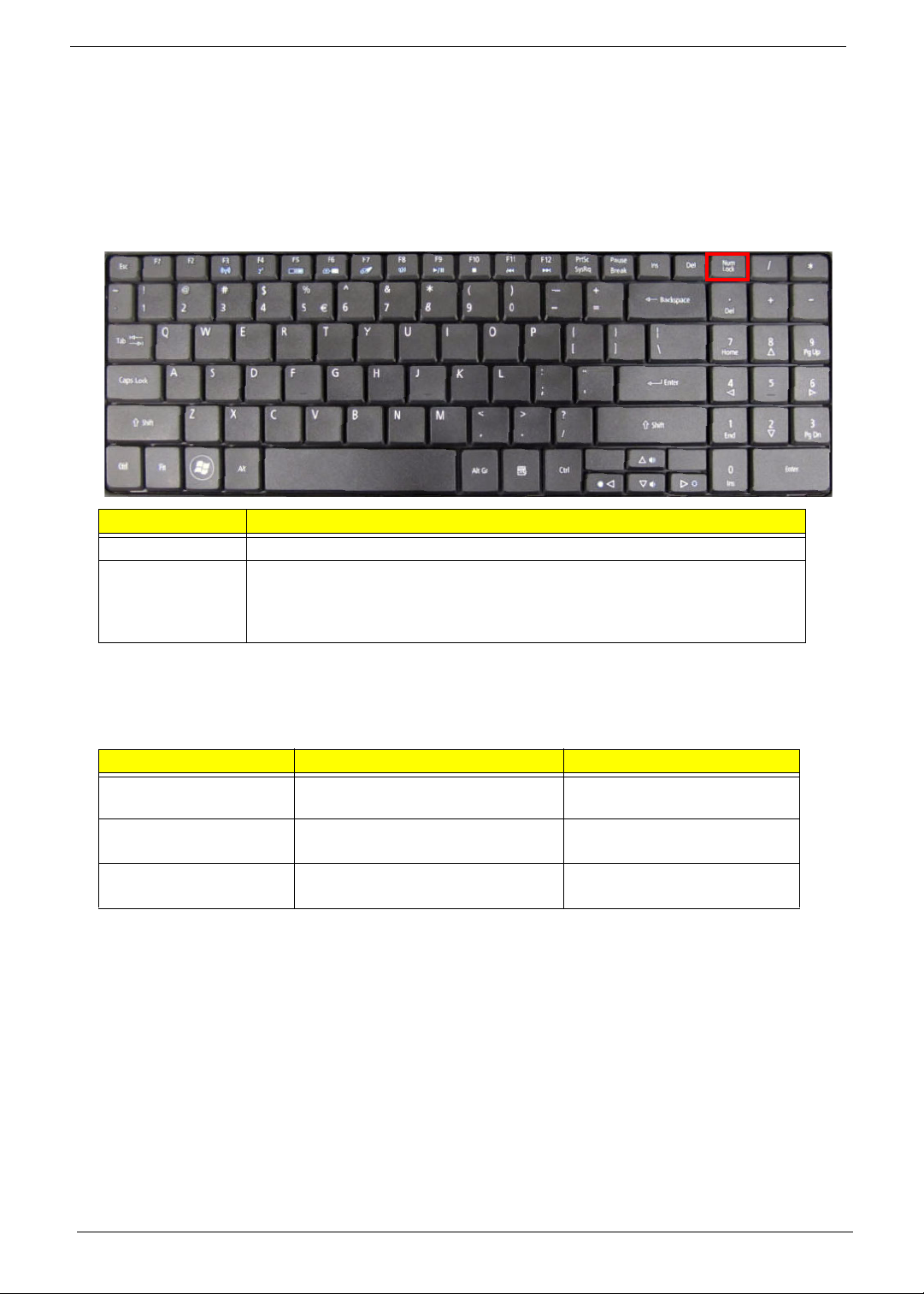
Using the Keyboard
The keyboard has full-sized keys and an embedded numeric keypad, separate cursor, lock, Windows, function
and special keys.
Lock Keys and embedded numeric keypad
The keyboard has two lock keys which you can toggle on and off.
The embedded numeric keypad functions like a desktop numeric keypad. It is indicated by small characters
located on the upper right corner of the keycaps. To simplify the keyboard legend, cursor-control key symbols
are not printed on the keys.
Lock key Description
Caps Lock When Caps Lock is on, all alphabetic characters typed are in uppercase.
Num Lock When Num Lock is on, the embedded keypad is in numeric mode. The keys
function as a calculator (complete with the arithmetic operators +, -, *, and /). Use
this mode when you need to do a lot of numeric data entry. A better solution
would be to connect an external keypad.
Desired access Num Lock on Num Lock off
Number keys on
embedded keypad
Type numbers in a normal manner.
Cursor-control keys on
embedded keypad
Hold <Shift> while using cursor-
control keys.
Hold <Fn> while using cursor-
control keys.
Main keyboard keys Hold <Fn> while typing letters on
embedded keypad.
Type the letters in a normal
manner.
Chapter 1 13
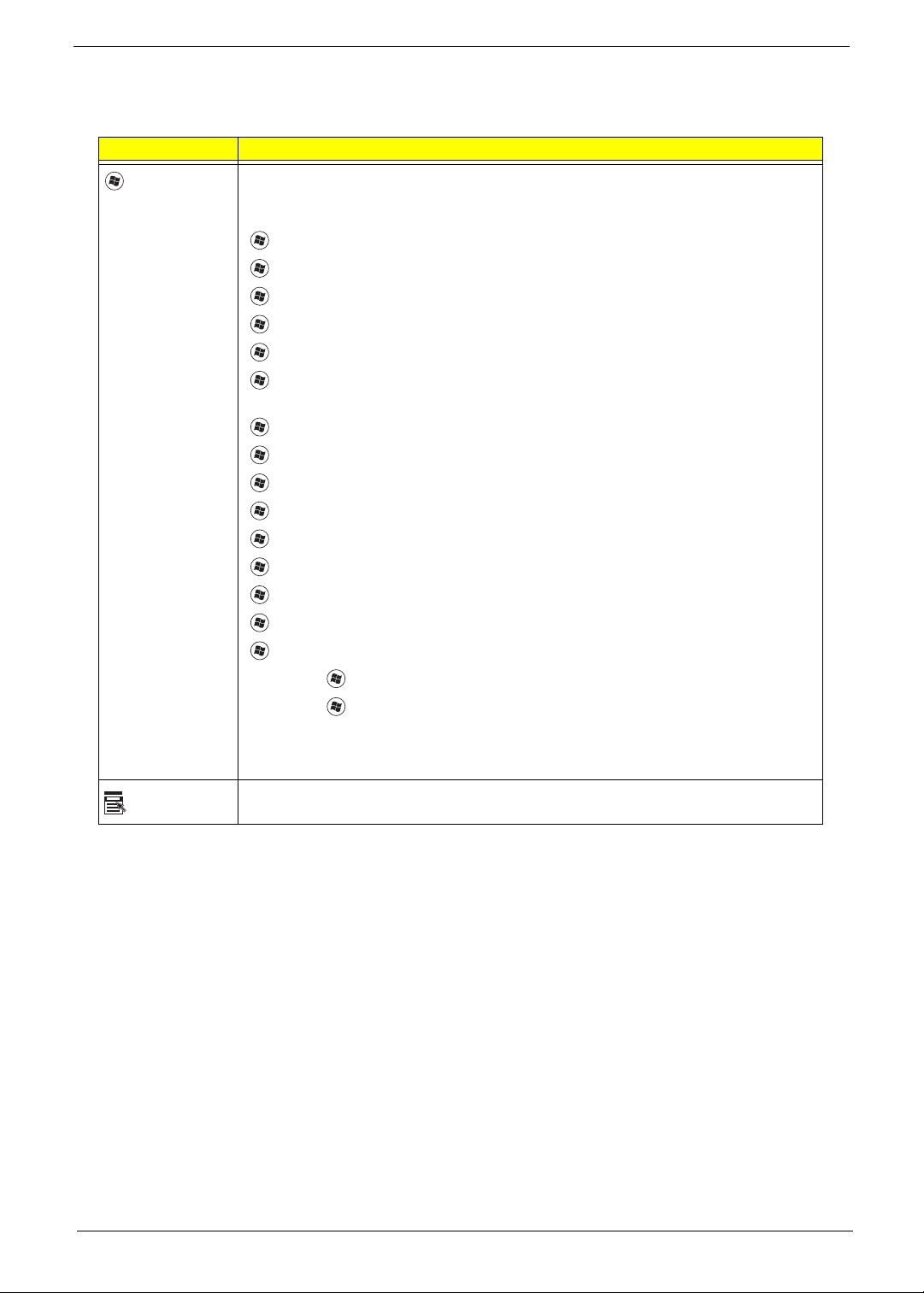
Windows Keys
The keyboard has two keys that perform Windows-specific functions.
Key Description
Windows key Pressed alone, this key has the same effect as clicking on the Windows Start button;
it launches the Start menu. It can also be used with other keys to provide a variety of
functions:
<>: Open or close the S tart menu
<> + <D>: Display the desktop
<> + <E>: Open Windows Explore
<> + <F>: Search for a file or folder
<> + <G>: Cycle through Sidebar gadgets
<> + <L>: Lock your computer (if you are connected to a network domain), or
switch users (if you're not connected to a network domain)
<> + <M>: Minimizes all windows
<> + <R>: Open the Run dialog box
<> + <T>: Cycle through programs on the taskbar
<> + <U>: Open Ease of Access Center
<> + <X>: Open Windows Mobility Center
<> + <BREAK>: Display the System Properties dialog box
<> + <SHIFT+M>: Restore minimized windows to the desktop
<> + <TAB>: Cycle through programs on the taskbar by using Windows Flip 3-D
<> + <SPACEBAR>: Bring all gadgets to the front and select Windows Sidebar
<CTRL> +
<> + <F>: Search for computers (if you are on a network)
<CTRL> + <> + <TAB>: Use the arrow keys to cycle through programs on the
taskbar by using Windows Flip 3-D
Note: Depending on your edition of Windows 7, some shortcuts may not function as
described.
Application
key
This key has the same effect as clicking the right mouse button; it opens the
application's context menu.
14 Chapter 1
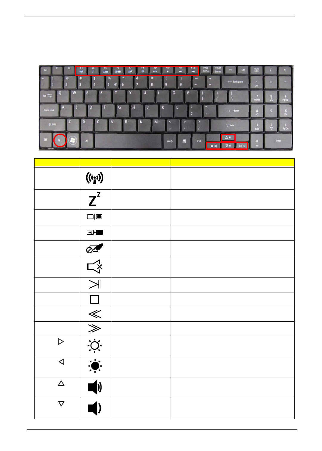
Hot Keys
The computer employs hotkeys or key combinations to access most of the computer’s controls like screen
brightness, volume output and the BIOS utility.
To activate hot keys, press and hold the <Fn> key before pressing the other key in the hotkey combination.
Hotkey Icon Function Description
<Fn> + <F3> Communication key Enables/disables the computer’s communication
devices. (Communication devices may vary by
configuration.)
<Fn> + <F4> Sleep Puts the comp uter in Sleep mode.
<Fn> + <F5> Display toggle S witches display output between the display
screen, external monitor (if connected) and both.
<Fn> + <F6> Screen blank Turns the display screen backlight off to save
power. Press any key to return.
<Fn> + <F7> Touchpad toggle Turns the internal touchpad on and off.
<Fn> + <F8> Speaker toggle Turns the speakers on and off.
<Fn> +<F9> Play/Pause Play or pause a selected media file.
<Fn> + <F10> Stop Stop playing the selected media file.
<Fn> +<F11> Previous Return to the previous media file.
<Fn> + <F12> Next Jump to the next media file.
<Fn> + < >
Brightness up Increases the screen brightness.
<Fn> + < >
Brightness down Decreases the screen brightness.
<Fn> + < >
Volume up Increases the sound volume.
<Fn> + < >
Volume down Decreases the sound volume.
Chapter 1 15
Hardware Specifications and Configurations
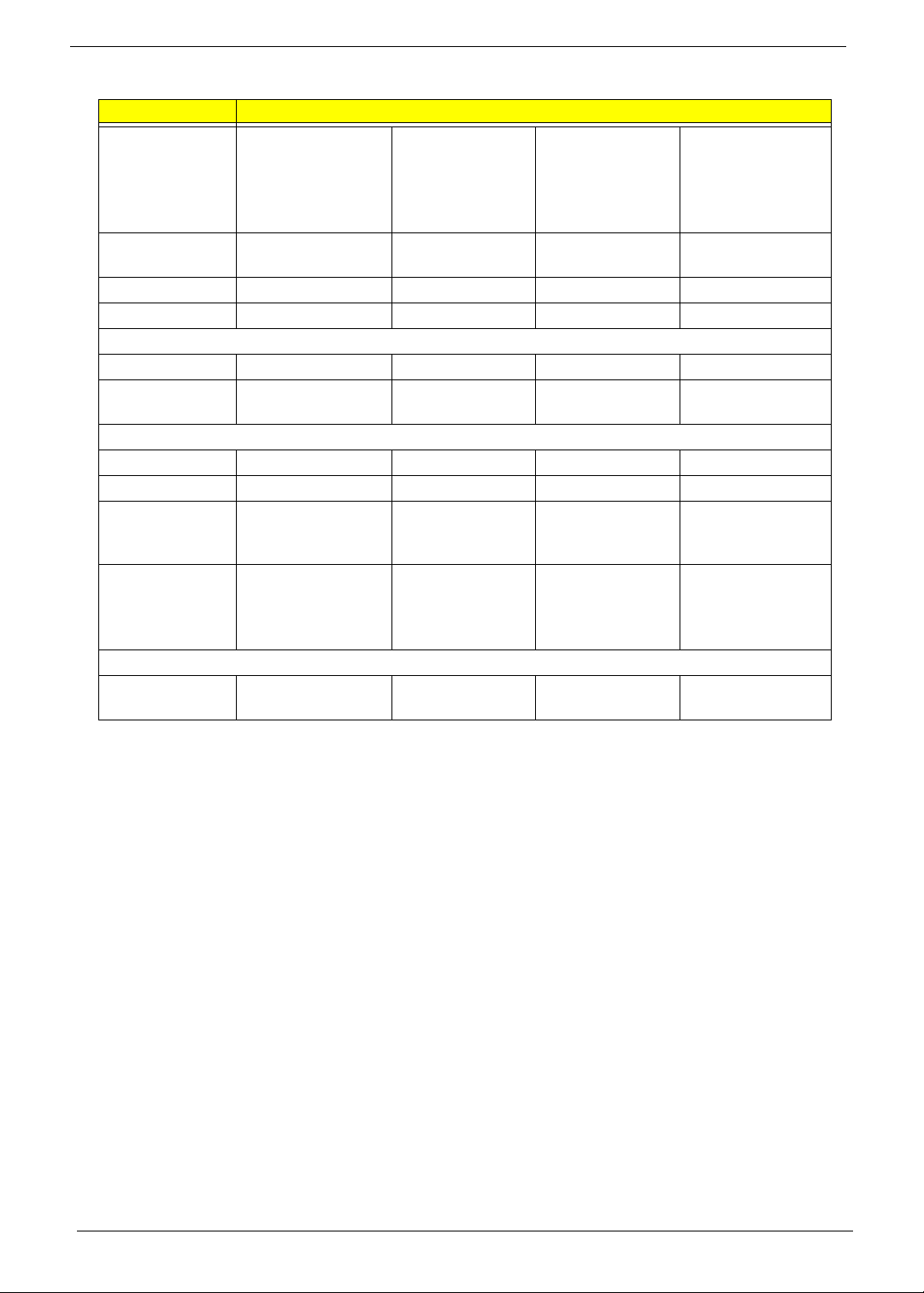
Processor
Processor Specifications
CPU Fan True Value Table
• Throttling 50%: On=99°C, Off=96°C
• OS Shutdown: 105°C
• H/W Shutdown: 110°C
Northbridge
Southbridge
Item Specification
CPU • Intel® Pentium® mobile processor*
• Intel® Celeron® mobile processor*
Type Intel Mobile PDC uPGA -478
Core Logic Mobile Intel® GL40/GM45 Express Chipset
CPU Package Micro uPGA-478 Package
Power 65 Watts
On-die Cache 4MB L2 cache
Front Side Bus 667/800/1066 MHz
Item
CPU
Speed
Cores
Bus
Speed
Mfg
Tech
Cache
Size
Package
Core
Voltage
Acer P/N
T1700 1.83 GHz 2 667 MHz 65 nm 1 MB PGA 1.075V-
1.175V
KC.17001.CMT
T3000 1.80 GHz 2 800 MHz 45 nm 1 MB PGA 0.95-
1.30V
KC.30001.CMT
T3100 1.90 GHz 2 800 MHz 45 nm 1 MB PGA 0.95-
1.30V
KC.31001.CMT
CM900 2.2 GHz 2 800 MHz N/A 1 MB PGA N/A KC.N0001.900
PMDT4300 2.10 GHz 2 800 MHz N/A 1 MB PGA N/A KC.34001.DTP
PMDT4400 2.20 GHz 2 800 MHz N/A 1 MB PGA N/A KC.42001.DTP
PMDT4500 2.30 GHz 2 800 MHz N/A 1 MB PGA N/A KC.45001.DTP
Fan On T e mp (°C) Fan Speed (rpm) SPL Spec (dBA)
45 3000 28
50 3300 31
55 3700 34
65 4100 37
75 4500 40
80 4500 40
Item Specification
Chipset Intel Cantiga GM45/GL40
Package uFCBGA-1329
Item Specification
Chipset ICH9-M
Package BGA-676
16 Chapter 1
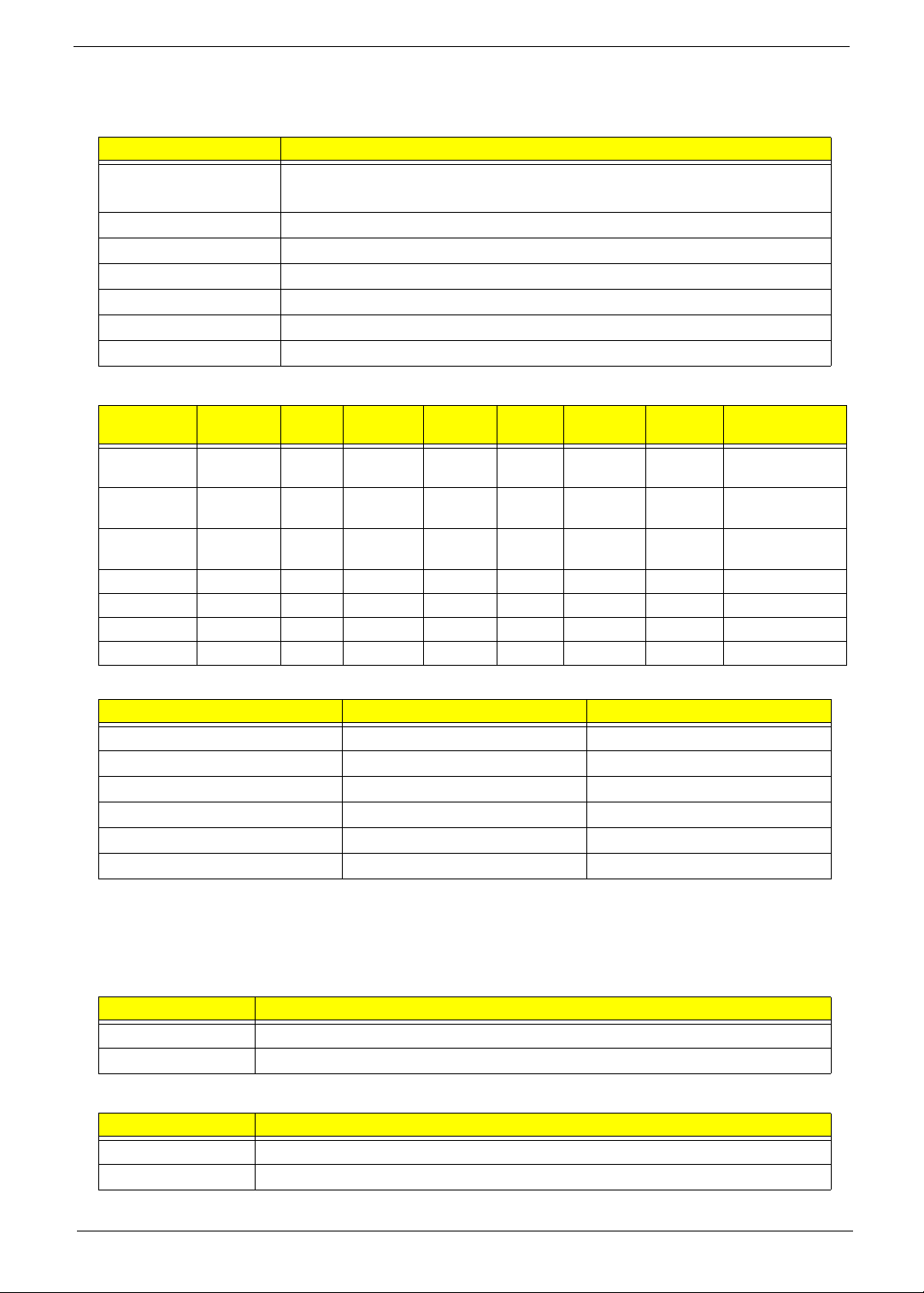
BIOS
System Memory
Item Specification
BIOS vendor Insyde BIOS
BIOS Version V0.06-T02
BIOS ROM type Flash
Features • Flash ROM 1MB
• Supports ISIPP
• Supports Acer UI
• Supports multi-boot
• Suspend to RAM (S3)/Disk (S4)
• Various hot-keys for system control
• Supports SMBUS 2.0, PCI2.3
• ACPI 2.0 compliance with Intel Speed Step support C1, C2,
C3, C4 and S3, S4 for mobile CPU
• DMI utility for BIOS serial number configurable/asset tag
• Supports PXE
• Supports Y2K solution
• Supports Win Flash Wake on LAN from S3
• Wake on LAN form S4 in AC mode
• System information
Item Specification
Memory controller ICH9-M
Memory size 4GB maximum
DIMM socket number 2
Supports memory size per socket 2GB
Supports maximum memory size 4GB (total)
Supports DIMM type 204-pin +1.5V DDRIII
Supports DIMM Speed 800/1066 MHz
Supports DIMM voltage 1.5V
Chapter 1 17
Memory Combinations
NOTE: Above table lists some system memory configurations. You may combine DIMMs with various
capacities to form other combinations. On above table, the configuration of slot 1 and slot 2 could be
reversed.
LAN Interface
Wireless Module 802.11b/g/Draft-N
Slot 1 Slot 2 Total Memory
0MB 512MB 512MB
0MB 1024MB 1024MB
0MB 2048MB 2048MB
512MB 512MB 1024MB
512MB 1024MB 1536MB
512MB 2048MB 2560MB
1024MB 0MB 1024MB
1024MB 512MB 1536MB
1024MB 1024MB 2048MB
1024MB 2048MB 3072MB
2048MB 0MB 2048MB
2048MB 512MB 2560MB
2048MB 1024MB 3072MB
2048MB 2048MB 4096MB
Item Specification
LAN Chipset Atheros AR8132L
LAN connector type RJ-45
LAN connector location Right side
Feature Support for 10/100
Item Specification
Manufacturer • Foxconn FOX ATH XB63 Foxconn Atheros XB63
minicard b/g
• Foxconn Wireless LAN Broadcom 4312 minicard b/g
Features • Mini PCIe WLAN module with dual-band, built-in
antenna
• Acer InviLink™ 802.11b/g/Draft-N*
• Acer InviLink™ 802.11b/g*
18 Chapter 1
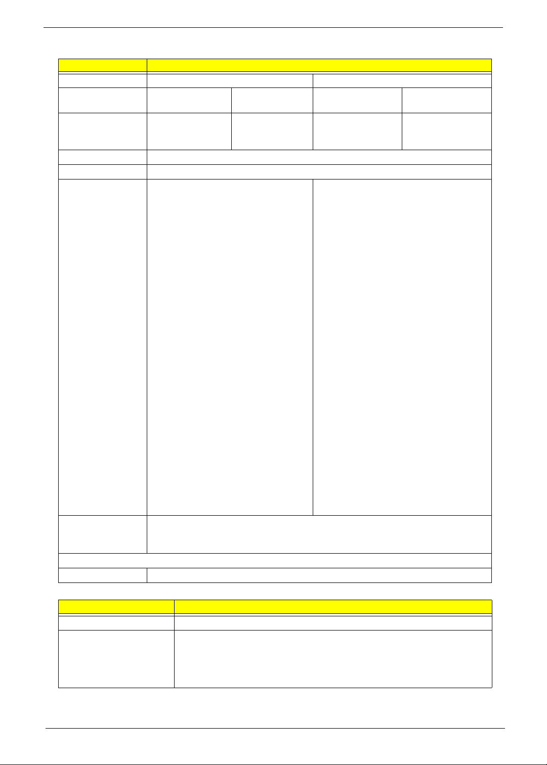
Hard Disk Drive Interface
Item Specification
Vendor & Model
Name
Seagate
ST9500325AS
ST9250315AS
Seagate
ST9320320AS
ST9160310AS
Toshiba
MK3255GSX
MK2555GSX
MK1655GSX
Western Digital
WD5000BEVT
WD3200BEVT
WD2500BEVT
WD1600BEVT
Capacity (MB) 500, 250 320, 160 320, 250, 160 500, 320, 250,
160
Bytes per sector 512 512 512 512
Data heads 4, 2 4, 2 4, 2, 2 4, 4, 3, 2
Drive Format
Disks 2, 1 2 or 1, 1 2, 1, 1 2, 2, 2, 1
Spindle speed
(RPM)
5400 5400 5400 5400
Performance Specifications
Buffer size 8 MB 8 MB 8 MB 8 MB
Interface SATA SATA SATA SATA
Internal transfer
rate (Mbits/sec,
max)
352 395~952 (typical) 850 Mbits/s
maximum
I/O data transfer
rate
(Mbytes/sec
max)
150 300 300 maximum
DC Power Requirements
Voltage
tolerance
5V ±5% 5V ±5% 5V ±5% 5V ±5%
Chapter 1 19
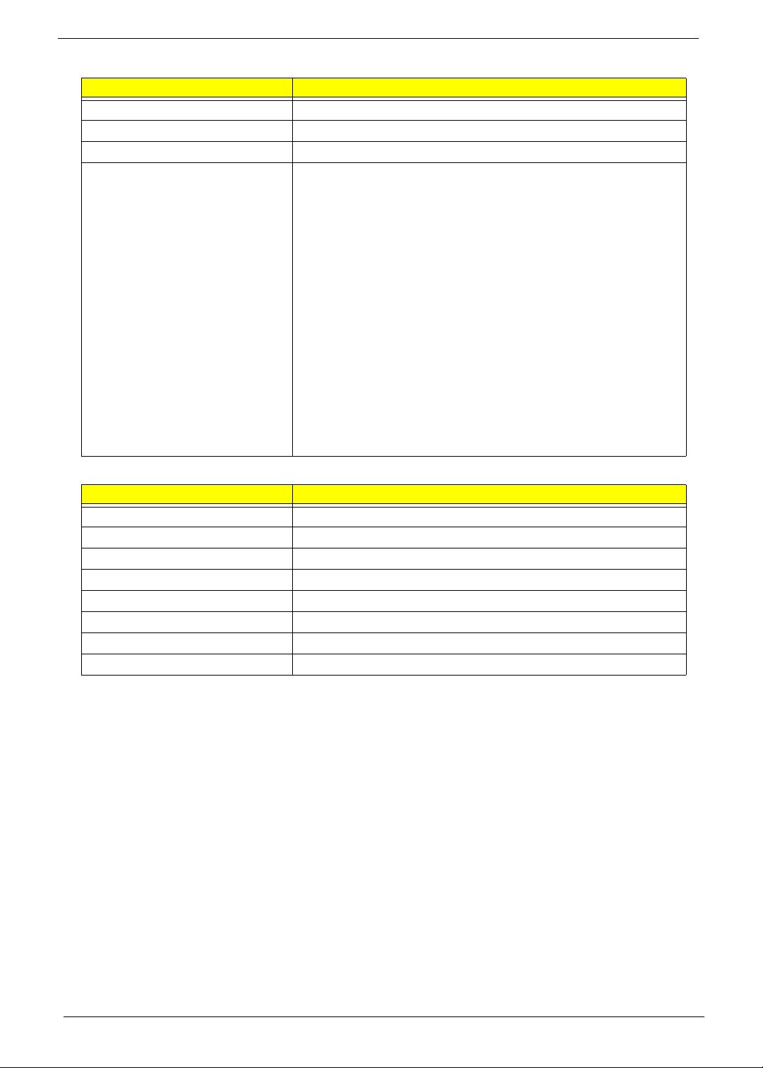
Super-Multi Drive Module
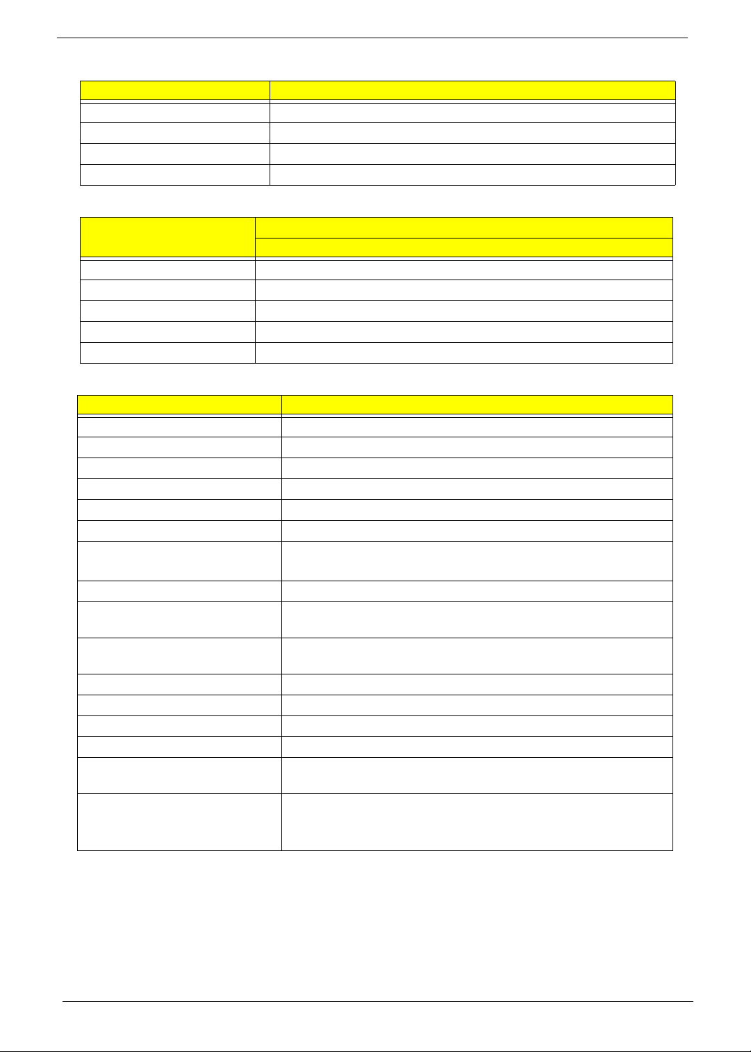
Audio Interface
Item Specification
Vendor & model name HLDS GT20N Sony AD7580S
Performance
Specification
With CD Diskette With DVD Diskette With CD Diskette With DVD Diskette
Transfer rate (MB/sec) Sustained:
3,600 KB/s (24x)
max.
Sustained:
11.08 Mbytes/s (8x)
max.
Sustained:
1,571 (typical)
Sustained:
10,993 (typical)
Buffer Memory 2 MB
Interface SATA
Applicable disc
formats
DVD-ROM:
4.7GB (Single Layer)
8.5GB (Dual Layer)
DVD-R:
3.95GB (Ver. 1.0: read only)
4.7GB (Ver. 2.0 for Authoring: read only)
4.7GB (Ver. 2.1 for General: read & write)
(DL) 8.5GB (Ver. 3.0)
DVD-RW:
4.7GB (Ver. 1.2/ Rev 1.0, 2.0, 3.0)
DVD-RAM: 1.46GB/side, 4.7GB/side (Ver.
2.2)
DVD+R: 4.7GB (Ver. 1.3)
(DL) 8.5GB (Ver. 1.1)
DVD+RW:
4.7GB (Vol.1 Ver.1.3)
CD-ROM Mode-1 data disc
CD-ROM Mode-2 data disc
CD-ROM XA, CD-I, Photo-CD Multi-
Session, Video CD
CD-Audio Disc
Mixed mode CD-ROM disc (data and audio)
CD-Extra
CD-Text
CD-R (Conforming to “Orange Book Part 2”:
read & write)
CD-RW (Conforming to “Orange Book Part
3”: read & write)
DVD Read:
DVD-ROM (DVD-5, DVD-9, DVD-10, DVD-18),
DVD-Video, DVD-Audio, SACD (Hybrid),
UDF DVD, DVD-R, DVD-R DL, DVD-R 3.95
GB, DVD-R Authoring, DVD-R Multi-Border,
DVD-RW, DVD+R, DVD+R DL, DVD+R Multi-
Session, DVD+RW, DVD-RAM V1.0, DVDRAM
V2.0 & 2.1 &2.2.
CD Read:
CD-DA, CD-ROM Mode-1, CD-ROM/XA Mode-
2 Form-1 and Mode-2 Form-2, CD-i, CD-i
Bridge, Video-CD (MPEG-1), Karaoke CD,
Photo-CD, Enhanced CD, CD Plus, CD Extra,
itrax
CD, CD-Text, UDF CD, CD-R, and CD-RW
DVD Write:
DVD Data & Video
CD Read:
CD-DA, CD-ROM Mode-1, CD-ROM/XA Mode-
2 Form-1 and Mode-2 Form-2, CD-i, Video-
CD, CD-Text
Loading mechanism Drawer (Solenoid Open)
Tact SW (Open)
Emergency Release (draw open hole)
Power Requirement
Input Voltage DC 5 V +/- 5%
Item Specification
Chipset Realtek ALC272X-GR
Features • High Definition Audio Codec with Dolby Digital Live
• One built-in mono speaker
• Built-in microphone
• MS-Sound compatible
20 Chapter 1
Power and Keyboard Controller
Battery
LCD 17”
Item Specification
Controller ENE KB926
Total number of keypads 99-/100-/103-key keyboard
Windows logo key Yes
Hotkeys See “Hot Keys” on page 14.
Item
Specification
6 Cell
Vendor & model name SANYO/SONY/PANASONIC/SAMSUNG/SIMPLO AS2009A
Battery Type Li-ion
Pack capacity 4400 mAh
Normal Voltage 2.2 Ah
Package configuration 3S2P
Item Specification
Vendor/model name CMO N173O6-L02
Screen Diagonal (mm) 439.4
Display Area (mm) 382.08 x 214.92
Display resolution (pixels) 1600 x 900
Pixel Pitch 0.2388
Display Mode Normal
Typical White Luminance (cd/m
2
)
(also called Brightness)
220
Contrast Ratio 600:1
Response Time (Optical Rise
Time/Fall Time) msec
8
Typical Power Consumption
(watt)
7
Weight 580 max.
Physical Size (mm) 398.1 x 232.8 x 5.5
Electrical Interface LVDS
Support Color 262K
Viewing Angle (up/down/right/
left)
20/45/45/45
Temperature Range (°C)
Operating
Storage (shipping)
0 to +50
-20 to +60
Loading...