


 Loading...
3M 1765, 1715, 1706, 1780, 1760 User Manual
...(4/10/2005)
1700 Overhead Projector
Illustrated Parts Breakdown
Beige colored machines: 1706, 1707, 1710, 1715
Gray colored machines:
1711, 1720, 1730, 1740, 1745, 1760, 1765, 1780
3M Visual Systems Department |
OHP Service Documentation Resource |
6801 River Place Boulevard |
Copyright © 2005. All Rights Reserved |
Austin, Texas 78726-9000 |
78-6970-7536-0 |
www.3m.com/meetings |
|

3M™ Overhead Projector 1700 Series |
Illustrated Parts Breakdown |
Revision History
Original Issue date: 1998
The release date, revision level, pages changed and a description of the modifications are listed below.
Revision |
Date |
Page(s) Changed |
Description |
Rev A |
1998 |
All pages |
First edition released. |
Rev B |
4/2001 |
All pages |
Added Gray machine references |
Rev C |
10/2001 |
Figure 5, Pages 13-14 |
Top Cover individual parts combined. |
Rev D |
5/2002 |
All pages |
Updated part nbrs and assembly nbrs. Added |
|
rev history page. |
||
|
|
|
|
|
|
Quick Ref Parts Index |
Added new Head Assemblies for Gray |
|
|
and Figure 1, |
machines. |
Rev E |
9/2002 |
Pages 5 and 6 |
Removed Head Assembly part nbrs for Beige |
|
machines. |
||
|
|
Figure 11, Page 25 |
|
|
|
Added new Roll Film Kit. |
|
|
|
|
|
Rev F |
4/2003 |
Figure 3, |
Updated part numbers for items 3 and 10. |
Page 10 |
|
||
|
|
|
|
|
|
All pages |
Added new Arm/ Focus, Top Cover |
Rev G |
3/2005 |
|
Assemblies. Updated kits, part nbrs, and |
|
|
|
Appendix information. |
All rights reserved. No part of this book covered by the copyrights hereon may be reproduced or copied in any
form or by any means-graphic, electronic, or mechanical, including photocopying, taping or information storage and retrieval systems-without written permission of 3M Visual Systems Department.
© 3M 2005. All Rights Reserved. |
ii |

3M™ Overhead Projector 1700 Series |
Illustrated Parts Breakdown |
||
|
Table of Contents |
|
|
INTRODUCTION ................................................................................................................................................... |
|
1 |
|
QUICK REFERENCE PARTS INDEX ............................................................................................................................. |
|
2 |
|
SECTION 0. MACHINE OVERVIEW............................................................................................................................. |
|
3 |
|
SECTION 1. HEAD ASSEMBLY .................................................................................................................................. |
|
4 |
|
SECTION 2. |
ARM AND FOCUS ASSEMBLY (BEIGE COLOR) ......................................................................................... |
|
6 |
SECTION 3. ARM AND FOCUS ASSEMBLY (GRAY COLOR) (SERIAL NUMBER 170006497 AND BELOW) ......................... |
8 |
||
SECTION 4. ARM/FOCUS/POST ASSEMBLY (GRAY COLOR) (SERIAL NUMBER 170006498 AND ABOVE) ..................... |
10 |
||
SECTION 5. POST ASSEMBLY ................................................................................................................................ |
|
11 |
|
SECTION 6. TOP COVER ASSEMBLY (SERIAL NUMBER 170000988 AND BELOW)...................................................... |
13 |
||
SECTION 7. TOP COVER ASSEMBLY (SERIAL NUMBER 170000989 AND ABOVE) ...................................................... |
15 |
||
SECTION 8. BASE ENCLOSURE .............................................................................................................................. |
|
16 |
|
SECTION 9. CONTROL MODULE ............................................................................................................................. |
|
18 |
|
SECTION 10. LAMP HOUSING (SINGLE) .................................................................................................................. |
|
20 |
|
SECTION 11. LAMP HOUSING (DUAL) ..................................................................................................................... |
|
22 |
|
SECTION 12. |
COOLING FAN................................................................................................................................... |
|
24 |
SECTION 13. |
ACCESSORIES .................................................................................................................................. |
|
26 |
SECTION 14. WIRE JUMPERS ................................................................................................................................ |
|
27 |
|
SECTION 15. |
HARDWARE KIT (NO PICTURE).......................................................................................................... |
|
29 |
APPENDIX A – 1700 SPECIFICATIONS............................................................................................................. |
|
30 |
|
© 3M 2005. All Rights Reserved. |
iii |

3M™ Overhead Projector 1700 Series |
Illustrated Parts Breakdown |
This page is intentionally blank
© 3M 2005. All Rights Reserved. |
iv |
3M™ Overhead Projector 1700 Series |
Illustrated Parts Breakdown |
INTRODUCTION
This Illustrated Parts Breakdown (IPB) Manual contains the information necessary to locate and identify assemblies, sub-assemblies, and specific parts of the 1700 Overhead Projector.
Part Numbers
All components available on a replacement basis are listed with their 3M identification number. The parts identification list opposite each illustration provides the description adequate to identify components. If the component is available only as part of the next higher assembly, the description column provides the next higher assembly description or identification number.
Locating and Identifying a Part
If physical appearance and general location of an item are known:
1.Use the IPB Section Titles to help determine which assembly or sub-assembly includes the item.
2.Refer to the view for the assembly or sub-assembly and locate the item on the exploded view. Match the part callout number to the corresponding number in the parts list.
3.Parts shown inside a dashed box can only be ordered as an assembly. Any part or mounting hardware shown outside the box is not included with the assembly.
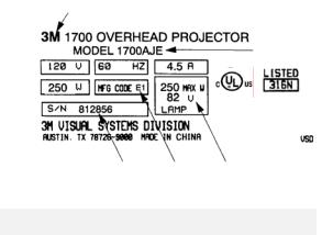
Machine Identification Plate
The serial number plate for the 1700 is located on the inside wall of the projector. The Machine Identification Plate is divided into the following components:
1.Product Name: The specific version number of the projector.
2.Model Number/Alpha Code: The series number of the projector followed by a three or four character alpha code identifier. The Alpha Code indicates the design level, specific product characteristics, power cord or distribution specific to a country.
3.Lamp: The electrical rating of the lamp.
4.MFG Code: The MFG Code indicates the year and quarter the projector was built. (See the example to the right):
5.S/N: The serial number assigned to this projector.
Ordering Parts
When ordering parts, include the following information:
1.Machine model number and serial number.
2.Parts identification number.
3.Part description.
4.Quantity required.
1
2
|
5 |
4 |
3 |
|
|
|
|
|
MFG Code |
|
|
|
Letter |
|
Digit |
E |
1997 |
1 |
Jan-Mar |
F |
1998 |
2 |
Apr-Jun |
H |
1999 |
3 |
Jul-Sep |
J |
2000 |
4 |
Oct-Dec |
K |
2001 |
1 |
Jan-Mar |
A |
2004 |
2 |
Apr-Jun |
C |
2005 |
3 |
Jul-Sep |
For U.S. retail customers: Call 1-800-650-8429, or fax 1-800-650-9268. Dealers: Refer to Dealers Guide. 3M Subsidiaries: Contact Export Operations.
© 3M 2005. All Rights Reserved. |
1 |
|
3M™ Overhead Projector 1700 Series |
|
Illustrated Parts Breakdown |
|||||
|
Quick Reference Parts Index |
|
|
|
|
|
||
|
|
|
|
|
|
|
|
|
|
Description |
|
Part |
|
Section |
|
Item |
|
|
|
|
Number |
|
No. |
|
No. |
|
|
Blade, Fan |
78-8054-1823-9 |
12 |
1 |
|
|||
|
|
|
|
|
|
|
||
|
Diode Kit, Inline |
78-8054-1836-1 |
12 |
|
8A |
|
||
|
|
|
|
|
|
|
||
|
Fresnel Lens, Dual-Element |
|
XO-0038-0820-1 |
7 |
3 |
|
||
|
|
|
|
|
|
|||
|
Fuse, 5 Amp, 5x20mm (Brazil only) |
26-1005-9599-5 |
12 |
3 |
|
|||
|
|
|
|
|
|
|
||
|
Singlet Head Assembly (1720, 1760, 1765 Gray color) |
78-8120-8554-2 |
1 |
|
8A |
|
||
|
|
|
|
|
|
|
||
|
Doublet Head Assembly (1730, 1780 Gray color) |
78-8120-8555-9 |
1 |
|
8B |
|
||
|
|
|
|
|
|
|||
|
Open Head Assembly (1711, 1740, 1745 Gray color) |
78-8120-8556-7 |
1 |
9 |
|
|||
|
|
|
|
|
|
|||
|
Lamp, Projection, ENX, 82V (Single) |
78-8011-1186-1 |
10 |
3 |
|
|||
|
|
|
|
|
|
|
||
|
Lamp, Projection, ENX, 82V (Dual) |
78-8011-1186-1 |
11 |
|
4A |
|
||
|
|
|
|
|
|
|
||
|
Lamp, Projection, FXL, 82V (1745 and 1765) |
78-8073-7100-6 |
11 |
|
4B |
|
||
|
|
|
|
|
|
|||
|
Motor, Fan, 120V |
78-8120-2914-4 |
12 |
7 |
|
|||
|
|
|
|
|
|
|
||
|
Power Cord, 10 ft., 120V |
78-8079-8822-1 |
8 |
|
4A |
|
||
|
|
|
|
|
|
|
||
|
Resistor, 1.2 Ohm, 0.25 tab |
78-8073-7127-9 |
9, 10 |
|
5A, 13 |
|
||
|
|
|
|
|
|
|||
|
Socket, Single Lamp, ENX |
78-8079-8820-5 |
10 |
2 |
|
|||
|
|
|
|
|
|
|||
|
Socket, Dual Lamp, Black |
78-8073-3017-6 |
11 |
3 |
|
|||
|
|
|
|
|
|
|||
|
Thermostat, Safety (ENX) |
78-8079-8872-6 |
10 |
7 |
|
|||
|
|
|
|
|
|
|
||
|
Top Cover Assembly, Single (Beige color) |
78-8114-9027-1 |
6 |
|
1A |
|
||
|
|
|
|
|
|
|
||
|
Top Cover Assembly, Dual (Beige color) |
78-8114-9021-4 |
6 |
|
1B |
|
||
|
|
|
|
|
|
|
||
|
Top Cover Assembly, Basic (Gray color) |
78-8120-8572-4 |
7 |
|
1A |
|
||
|
|
|
|
|
|
|
||
|
Top Cover Assembly, Lamp Changer (Gray color) |
78-8120-8573-2 |
7 |
|
1B |
|
||
|
|
|
|
|
|
|
|
|
IMPORTANT NOTICE
3M reserves the right to sell or furnish NEW OR RECONDITIONED PARTS. New and reconditioned parts are covered by the same 3M new parts limited warranty.
© 3M 2005. All Rights Reserved. |
2 |
3M™ Overhead Projector 1700 Series |
Illustrated Parts Breakdown |
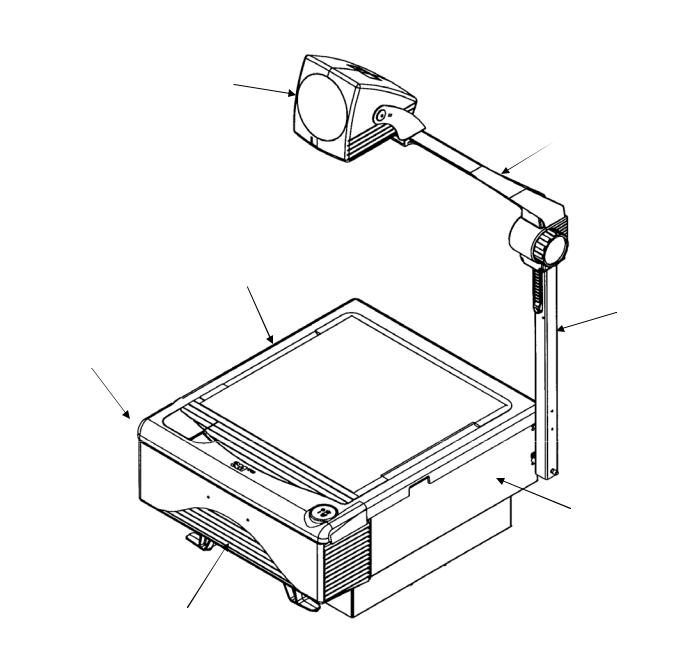
Section 0. Machine Overview
Head Assembly
(See Section 1)
Top Cover Assembly
(See Sections 6 and 7)
Control Module
(See Section 9)
Arm and Focus Assembly
(See Sections 2, 3 and 4)
Post
Assembly
(See
Section 5)
Base Enclosure
(See Section 8)
Lamp Housing (Single) |
Accessories |
(See Section 10) |
(See Section 13) |
Lamp Housing (Dual) |
Wire Jumpers |
(See Section 11) |
(See Section 14) |
Cooling Fan |
Hardware Kit |
(See Section 12) |
(See Section 15) |
© 3M 2005. All Rights Reserved. |
3 |
3M™ Overhead Projector 1700 Series |
Illustrated Parts Breakdown |
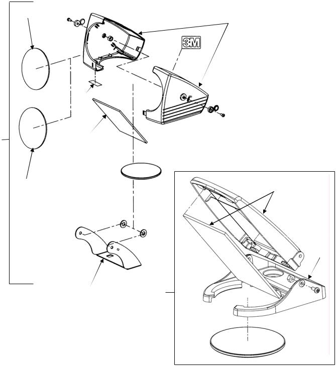
Section 1. Head Assembly
1
2
Closed Head
5
8 |
4 |
1, 3
6
7 |
9 |
NOTE:
Screws, nuts, bolts, clips, and other small hardware are contained in the Hardware Kit: 78-8114-9023-0 (See Section 15).
Open Head
10
11
 3
3
© 3M 2005. All Rights Reserved. |
4 |

|
3M™ Overhead Projector 1700 Series |
Illustrated Parts Breakdown |
||||
|
|
|
Head Assembly Parts List |
|
|
|
|
|
|
|
|
|
|
|
Item |
3M |
|
Description |
Qty. |
|
|
No. |
Part Number |
|
|
|
|
|
1 |
78-8114-8795-4 |
Lens, Doublet Element |
|
2 |
|
|
|
|
|
|
|
|
|
2A |
78-8120-2934-2 |
Head Halves, Singlet (Beige color) |
1 |
|
|
|
|
|
|
|
|
|
|
2B |
78-8120-2935-9 |
Head Halves, Doublet (Beige color) |
1 |
|
|
|
|
|
|
|
|
|
|
2C |
78-8120-8451-1 |
Head Halves, Singlet (Gray color) |
1 |
|
|
|
|
|
|
|
|
|
|
2D |
78-8120-8464-4 |
Head Halves, Doublet (Gray color) |
1 |
|
|
|
|
|
|
|
|
|
|
3 |
78-8014-8951-5 |
Lens, Wide Angle, 293mm (Singlet Head only) |
1 |
|
|
|
|
|
|
|
|
|
|
4 |
78-8114-8812-7 |
Mirror |
|
1 |
|
|
|
|
|
|
|
|
|
5 |
78-8120-3192-6 |
Label, Head |
|
1 |
|
|
|
|
|
|
|
|
|
6 |
78-8120-2927-6 |
Lens, Head |
|
1 |
|
|
|
|
|
|
|
|
|
7 |
78-8120-3072-0 |
Bracket, Head Mount, Closed Singlet (Gray color only) |
1 |
|
|
|
|
|
|
|
|
|
|
8A |
78-8120-8554-2 |
Singlet Head Assembly (1720, 1760, 1765 Gray color) |
1 |
|
|
|
|
|
|
|
|
|
|
8B |
78-8120-8555-9 |
Doublet Head Assembly (1730, 1780 Gray color) |
1 |
|
|
|
|
|
|
|
|
|
|
9 |
78-8120-8556-7 |
Open Head Assembly (1711, 1740, 1745 Gray color) |
1 |
|
|
|
|
|
|
|
|
|
|
10 |
78-8120-8501-3 |
Open Singlet Mirror Assembly |
1 |
|
|
|
|
|
|
|
|
|
|
11 |
(Not available) |
Housing, Lens, Split, Open Singlet |
1 |
|
|
|
|
|
|
|
|
|
© 3M 2005. All Rights Reserved. |
5 |

3M™ Overhead Projector 1700 Series |
Illustrated Parts Breakdown |
Section 2. Arm and Focus Assembly (Beige color)
1 
2
12
11
9 10
6
7, 8
4 3
See Section 5
5
NOTE:
Screws, nuts, bolts, clips, and other small hardware are contained in the Hardware Kit: 78-8114-9023-0 (See Section 15).
© 3M 2005. All Rights Reserved. |
6 |
|
3M™ Overhead Projector 1700 Series |
Illustrated Parts Breakdown |
|||||
|
|
Arm and Focus Assembly (Beige color) Parts List |
|
|
|
||
|
|
|
|
|
|
|
|
|
Item |
3M |
|
Description |
|
Qty. |
|
|
No. |
Part Number |
|
|
|
|
|
|
1 |
78-8114-8983-6 |
Shim, Head Leveling |
|
1 |
|
|
|
|
|
|
|
|
|
|
|
2 |
78-8073-3035-8 |
Arm, Focus |
|
1 |
|
|
|
|
|
|
|
|
|
|
|
3 |
78-8120-2920-1 |
Plate, Standoff |
|
1 |
|
|
|
|
|
|
|
|
|
|
|
4 |
78-8120-2925-0 |
Pad, Wear |
|
2 |
|
|
|
|
|
|
|
|
|
|
|
5 |
78-8064-1601-8 |
Knob, Focus |
|
1 |
|
|
|
|
|
|
|
|
|
|
|
6 |
78-8073-3041-6 |
Cap, Focus Arm |
|
1 |
|
|
|
|
|
|
|
|
|
|
|
7 |
78-8079-8745-4 |
Gear, Focus |
|
1 |
|
|
|
|
|
|
|
|
|
|
|
8 |
(Not available) |
Lubricant, Nye Rheolube 368 |
|
AR |
|
|
|
|
|
|
|
|
|
|
|
9 |
78-8079-8747-0 |
Bar, Pressure |
|
1 |
|
|
|
|
|
|
|
|
|
|
|
10 |
78-8079-8743-9 |
Clamp, Friction |
|
1 |
|
|
|
|
|
|
|
|
|
|
|
11 |
78-8079-8744-7 |
Rack, Focus |
|
1 |
|
|
|
|
|
|
|
|
|
|
|
12 |
26-1009-3653-8 |
Cap, Post |
|
1 |
|
|
|
|
|
|
|
|
|
|
© 3M 2005. All Rights Reserved. |
7 |
Loading...