


1615 AHGS
3M 1615 AHGS, 1610 AJA, 1615 AHGU, 1615 AAGP, 1615 AAGT Illustrated Parts Breakdown
...
1600 Overhead Projector
Illustrated Parts Breakdown
3M Visual Systems Division O.H.P. Service Documentation Resource
6801 River Place Boulevard Copyright © 2002, 3M IPC. All Rights Reserved
Austin, Texas 78726-9000 78-6970-7536-0

Revision History
Original Issue date: 8/2002
The release date, revision level, pages changed and a description of the modifications are listed below.
Revision Date Page(s) Changed Description
Rev A 4/2001 All pages First edition released
Rev B 8/2002 Table Of Contents,
Quick Reference
Parts Index,
and Figure 0,
Pages 2, 3, and 4
Figure 1,
Page 6
Figure 5,
Pages 12 and 13
Figure 8,
Page 17
Figure 9,
Page 18
NOTE: Blue text indicates a link to that page.
Removed reference
for 230V Electrical
Small Parts Kit,
Figure 9.
Removed part
numbers for Arm and
Post assemblies and
added Note 1.
Removed item #3,
Reflector, Aluminized
Glass.
Changed Kit name to
Small Parts Kit and
changed kit number
from 78-8120-8471-9
to 78-8120-8486-7.
Updated list of
included parts.
Removed Figure 9.
Combined 120/127V
and 230V Kits into one
Small Parts Kit on
Figure 8.
i
3M™ Overhead Projector 1600 Series Illustrated Parts Breakdown
Illustrated Parts Breakdown (IPB)
This Illustrated Parts Breakdown (IPB) Manual contains the information necessary to locate and identify
assemblies, sub-assemblies, and specific parts of the 1600 Overhead Projector.
Part Numbers
All components available on a replacement basis are listed with their 3M identification number. The parts
identification list opposite each illustration provides the description adequate to identify components. If the
component is available only as part of the next higher assembly, the description column provides the next
higher assembly description or identification number.
Locating and Identifying a Part
If physical appearance and general location of an item are known:
1. Use the IPB Section Titles to help determine which assembly or sub-assembly includes the item.
2. Refer to the view for the assembly or sub-assembly and locate the item on the exploded view. Match the
part callout number to the corresponding number in the parts list.
3. Parts shown inside a dashed box can only be ordered as a module or kit. Any part or mounting hardware
shown outside the box is not included with the assembly.
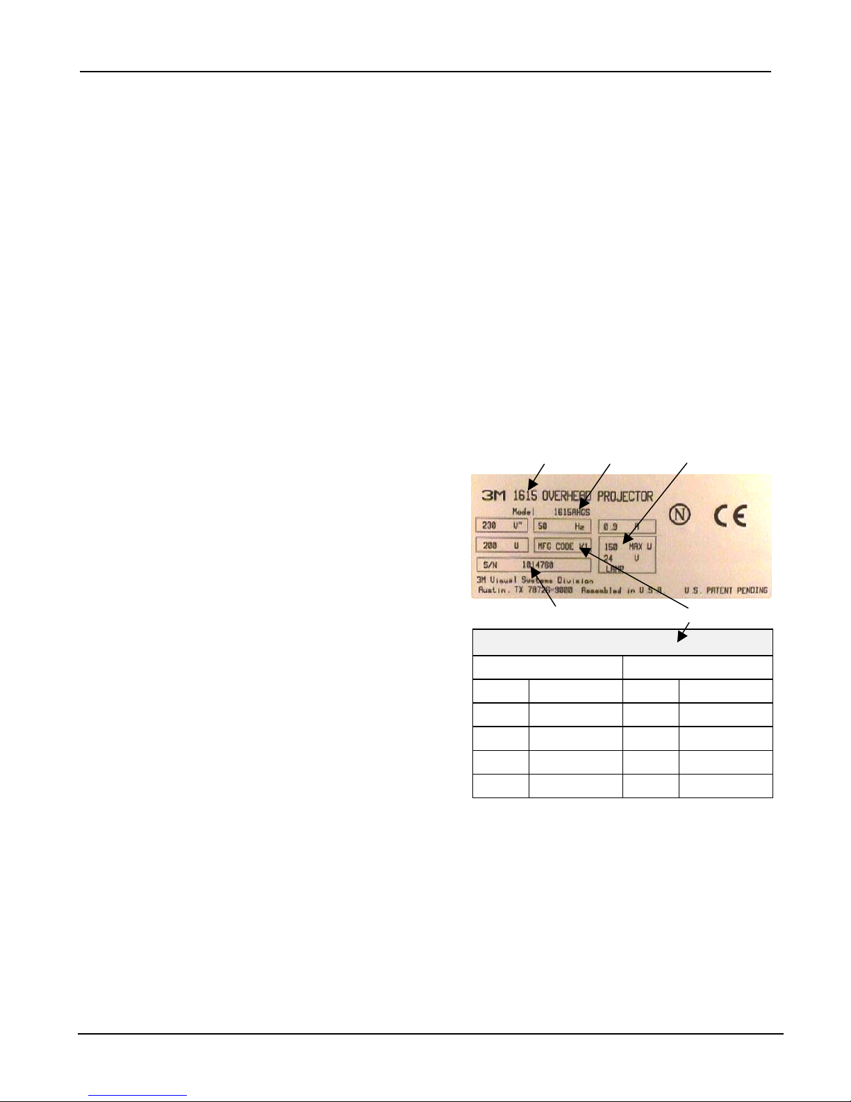
Machine Identification Plate
1
2
The serial number plate for the 1600 is located on the
bottom of the projector. The Machine Identification
Plate is divided into the following components:
1. Product Name: The specific version number of the
projector.
2. Model Number/Alpha Code: The series number of the
projector followed by a three or four character alpha
code identifier. The Alpha Code indicates the design
level, specific product characteristics, power cord or
distribution specific to a country.
3. Lamp: The electrical rating of the lamp.
4. MFG Code: The MFG Code indicates the year and
quarter the projector was built. (See the example to
the right):
5. S/N: The serial number assigned to this projector.
H 1999 1 Jan-Mar
J 2000 2 Apr-Jun
K 2001 3 Jul-Sep
5
MFG Code
Letter Digit
Ordering Parts
When ordering parts, include the following information:
L 2002 4 Oct-Dec
M 2003 1 Jan-Mar
1. Machine model number and serial number.
2. Parts identification number.
3. Part description.
4. Quantity required.
For U.S. retail customers: Call 1-800-650-8429, or fax 1-800-650-9268. Dealers: Refer to Dealers Guide.
3M Subsidiaries: Contact Export Operations.
3
4
© 3M IPC 2002 1

3M™ Overhead Projector 1600 Series Illustrated Parts Breakdown
Table of Contents
ILLUSTRATED PARTS BREAKDOWN (IPB) ....................................................................................1
FIGURE 0. MACHINE OVERVIEW..............................................................................................................3
IGURE 1. HEAD AND FOCUS ARM ASSEMBLY (10 INCH STAGE).............................................................5
F
F
IGURE 1. HEAD AND FOCUS ARM ASSEMBLY (10 INCH STAGE) PARTS LIST..........................................6
FIGURE 2. HEAD AND FOCUS ARM ASSEMBLY (A4 STAGE) ...................................................................7
FIGURE 2. HEAD AND FOCUS ARM ASSEMBLY (A4 STAGE) PARTS LIST .................................................8
FIGURE 3. TOP COVER ASSEMBLY ...........................................................................................................9
FIGURE 3. TOP COVER ASSEMBLY PARTS LIST......................................................................................10
FIGURE 4. BASE ASSEMBLY AND PARTS LIST ........................................................................................11
FIGURE 5. INTERNAL COMPONENTS (10 INCH STAGE) ...........................................................................12
FIGURE 5. INTERNAL COMPONENTS (10 INCH STAGE) PARTS LIST........................................................13
FIGURE 6. INTERNAL COMPONENTS (A4 STAGE) ...................................................................................14
FIGURE 6. INTERNAL COMPONENTS (A4 STAGE) PARTS LIST ...............................................................15
FIGURE 7. HARDWARE KIT ....................................................................................................................16
FIGURE 8. SMALL PARTS KIT .................................................................................................................17
APPENDIX A. SPECIFICATIONS ...............................................................................................................18
WHERE TO GET ADDITIONAL INFORMATION ......................................................................................... 22
3M reserves the right to sell or furnish NEW OR RECONDITIONED PARTS.
New and reconditioned parts are covered by the same 3M new parts limited warranty.
IMPORTANT NOTICE
© 3M IPC 2002 2

3M™ Overhead Projector 1600 Series Illustrated Parts Breakdown
Quick Reference Parts Index
Description Part
Number
Mirror Module (10 inch and A4 Stage) 78-8120-8444-6 1 and 2 1
Head Module (10 inch and A4 Stage) 78-8120-8478-4 1 and 2 2
Arm/Post Module (A4 Stage) 78-8120-8465-1 2 3
Focus Kit (A4 Stage) 78-8120-8466-9 2 4
Stage Module (10 inch) 78-8120-8468-5 3 1A
Stage Module (A4) 78-8120-8469-3 3 1B
Fresnel Lens, Single Element (10 inch Stage) 78-8120-8487-5 3 2A
Fresnel Lens, Dual Element (A4 Stage) 78-8120-8488-3 3 2B
Lamp, Projection, FCS, 150W, 24V
(10 inch and A4 Stage)
Lamp Module (U.S. version, lamp, on/off switch) 78-8120-8474-3 5 4A
Lamp Module (Latin America version, lamp, interlock) 78-8120-8473-5 5 4B
Lamp Module (A4 Stage, lamp, reflector) 78-8120-8475-0 6 4
78-8120-3026-6 5 and 6 2
Figure
No.
Item
No.
Condenser Module (A4 Stage) 78-8120-8476-8 6 1
Reflector, Aluminized Glass RO-0-3-- - 221-0 5 and 6 3
Hardware Kit 78-8120-8477-6 7 0
Small Parts Kit 78-8120-8486-7 8 0
© 3M IPC 2002 3
3M™ Overhead Projector 1600 Series Illustrated Parts Breakdown
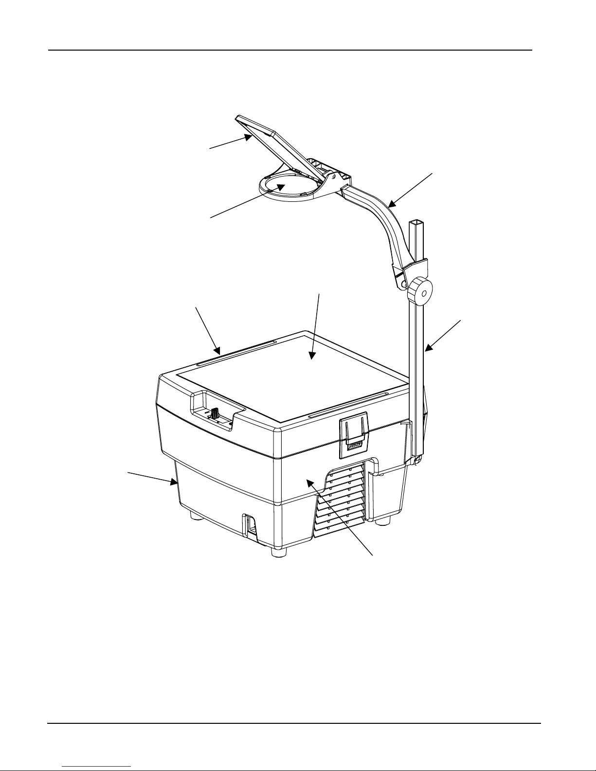
Figure 0. Machine Overview
Mirror Module
Spare Parts
(See Figures 1 and 2)
Head Module
Spare Parts
(See Figures 1 and 2)
Stage Module
Spare Parts
(See Figure 3)
Fresnel Lens
(See Figure 3)
Focus Arm
Spare Parts
(See Figures 1 and 2)
Post Assembly
Spare Parts
(See Figures 1 and 2)
Base Assembly
Spare Parts
(See Figure 4)
Hardware Kit
(See Figure 7)
Small Parts Kit
(See Figure 8)
© 3M IPC 2002 4
Internal Components
and Lamp Module
Spare Parts
(See Figures 5 and 6)
3M™ Overhead Projector 1600 Series Illustrated Parts Breakdown
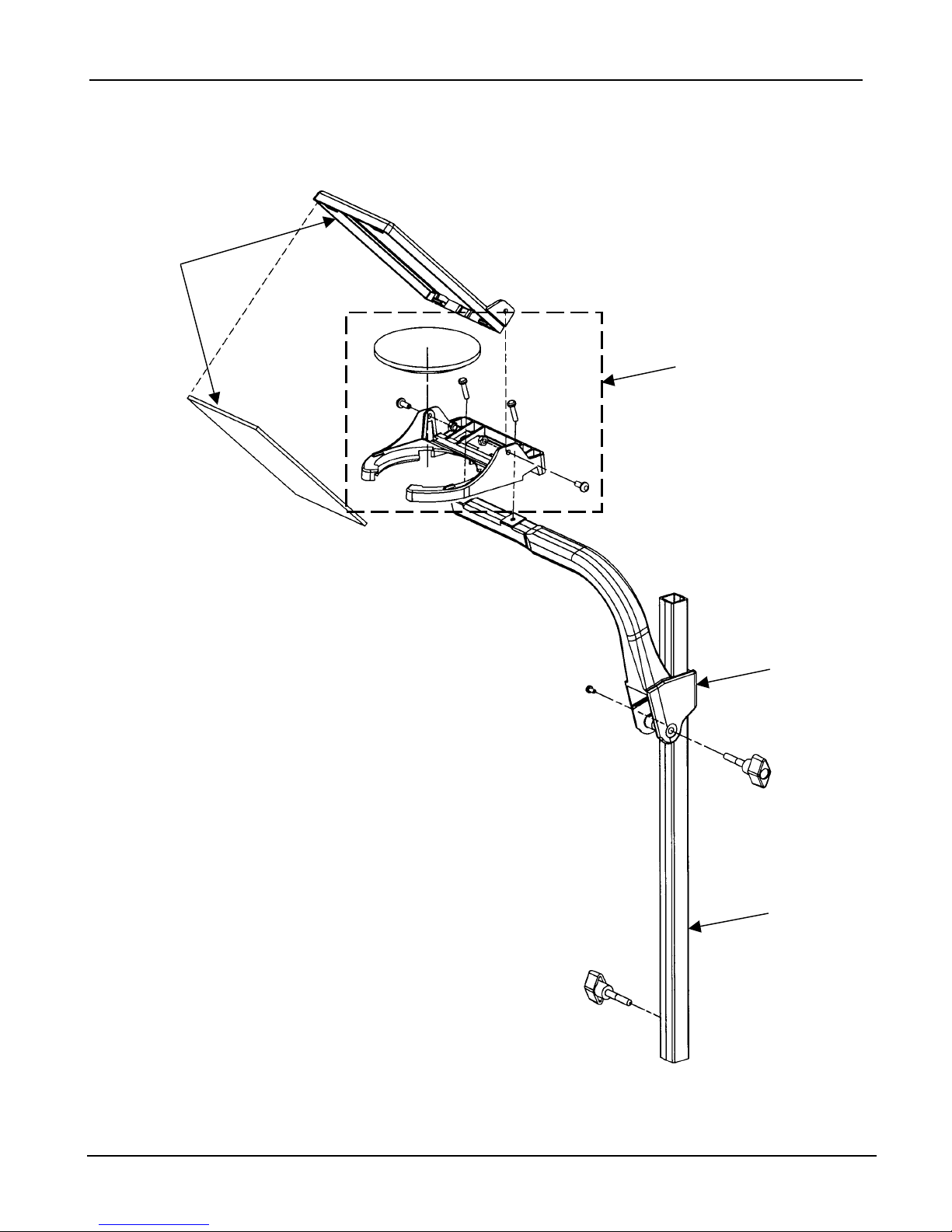
Figure 1. Head and Focus Arm Assembly (10 inch Stage)
1
2
3
4
© 3M IPC 2002 5

3M™ Overhead Projector 1600 Series Illustrated Parts Breakdown
Figure 1. Head and Focus Arm Assembly (10 inch Stage) Parts List
Item
No.
1 78-8120-8444-6 Mirror Module 1
2 78-8120-8478-4 Head Module 1
3 (See Note 1) Arm, Focus 1
4 (See Note 1) Post 1
3M
Part Number
Description Qty.
NOTE 1:
Please contact the 3M Parts Center for ordering information on these items.
© 3M IPC 2002 6
 Loading...