

Page 1
Enterprise Management Suite
User Guide for VCX
Components
VCX™ V7000 IP Telephony Solution
System Release 7.1
Part Number 900-0385-01 Rev AB
Published May 2007
http://www.3com.com/
TM
V7000
Page 2

3Com Corporation
350 Campus Drive
Marlborough, MA
01752-3064
Copyright © 2001–2007, 3Com Corporation. All rights reserved. No part of this
documentation may be reproduced in any form or by any means or used to make any
derivative work (such as translation, transformation, or adaptation) without written
permission from 3Com Corporation.
3Com Corporation reserves the right to revise this documentation and to make
changes in content from time to time without obligation on the part of 3Com
Corporation to provide notification of such revision or change.
3Com Corporation provides this documentation without warranty, term, or condition
of any kind, either implied or expressed, including, but not limited to, the implied
warranties, terms, or conditions of merchantability, satisfactory quality, and fitness
for a particular purpose. 3Com may make improvements or changes in the product(s)
and/or the program(s) described in this documentation at any time.
If there is any software on removable media described in this documentation, it is
furnished under a license agreement included with the product as a separate
document, in the hardcopy documentation, or on the removable media in a directory
file named LICENSE.TXT or !LICENSE.TXT. If you are unable to locate a copy, please
contact 3Com and a copy will be provided to you.
UNITED STATES GOVERNMENT LEGENDS:
If you are a United States government agency, then this documentation and the
software described herein are provided to you subject to the following:
United States Government Legend: All technical data and computer software is
commercial in nature and developed solely at private expense. Software is delivered
as Commercial Computer Software as defined in DFARS 252.227-7014 (June 1995)
or as a commercial item as defined in FAR 2.101(a) and as such is provided with only
such rights as are provided in 3Com’s standard commercial license for the Software.
Technical data is provided with limited rights only as provided in DFAR 252.227-7015
(Nov 1995) or FAR 52.227-14 (June 1987), whichever is applicable. You agree not to
remove or deface any portion of any legend provided on any licensed program or
documentation contained in, or delivered to you in conjunction with guide.
Unless otherwise indicated, 3Com registered trademarks are registered in the United
States and may or may not be registered in other countries.
3Com and the 3Com logo are registered trademarks of 3Com Corporation. VCX is a
trademark of 3Com Corporation.
Other brand and product names may be registered trademarks or trademarks of their
respective holders.
Page 3

CONTENTS
ABOUT THIS GUIDE
Related Documentation 13
Your Comments 14
1 3COM VCX IP TELEPHONY SERVER
Installing a License on a VCX Server 15
Obtaining a License 15
Copying the License File to the EMS Server 16
Uploading a License to a VCX Server 16
Activating a License on a VCX Server 16
Managing License Files 17
Viewing License Details 17
Viewing License Components 18
Viewing System Information 18
Creating Backup Configuration Files 19
Creating a Backup File 19
Setting the Current Configuration as Baseline 19
Restoring Backup Configuration Files 20
Recovering a Failed Restore 21
Starting and Stopping VCX Services 21
Golden Template Configuration 22
Verifying State of the VCX IP Telephony Server 22
Verifying VCX IP Telephony Server Software Version 22
VCX IP Telephony Server Identification Tab 23
Identification Tab Location 23
Verifying the Type of Office Configured 24
Verifying the Type of Components Installed on a Server 25
Verifying the Amount of Disk Spaced Used on an IP Telephony Server 25
Configuring Date and Time Variables for the IP Telephony Server 25
Configuring the Date of an IP Telephony Server 26
Configuring the Time of an IP Telephony Server 26
Page 4

4
Configuring the Timezone of an IP Telephony Server 26
Configuring Authorization Station Agents 27
Adding Authorized Station Agents 27
Deleting Authorized Station Agents 27
Enabling and Disabling the Web Provisioning Server (Tomcat) 28
Rediscovering the IP Telephony Server in EMS 28
Back-end Server Maintenance 29
Monitoring XML Accounting Server Activity on the XML Accounting
Server 29
Restarting Systems and Services 29
Reserving and Unreserving the Back-end Server 30
Updating the Server State 30
Configuring Replication for the VCX Data Server 31
Setting Up Replication for a VCX Data Server 31
Dropping Replication for a VCX Data Server 31
Checking Replication Status on a VCX Data Server 32
Deleting Replication Errors on the VCX Data Server 32
Managing SSH Scripts 32
RAID Monitoring 33
UPS Monitoring 33
Setting Up UPS Master/Slaves 33
Enabling UPS Monitoring 33
Viewing UPS Monitoring Information 34
Viewing UPS Slaves 34
2 CONFIGURING THE VCX DATA SERVER
VCX Data Server Database Configuration 35
Changing the VCX Data Server Database Name 35
Changing the VCX Data Server Database Server Name 35
Changing the VCX Data Server Database User Name 36
Changing the VCX Data Server Database User Password 36
Configuring the VCX Data Server Database Keep Alive Timeout 36
Configuring the VCX Data Server Client Activity Interval 37
Configuring VCX Data Server Client Request Threads 37
Configuring the VCX Data Server Logging Level 37
Enabling VCX Data Server Packet Tracing 38
VCX Data Server Configuration Tab Descriptions 38
Page 5

Tab Location 38
3 Q Protocol Configuration 38
BES Common Configuration 39
BES Common Statistics 39
Flow Control Configuration 40
Identification 40
State 40
VCX Data Server Maintenance 41
Restarting the VCX Data Server 41
Shutting Down the VCX Data Server 41
Verifying the VCX Data Server State 42
3 CONFIGURING THE XML ACCOUNTING SERVER
Configuring the Client Activity Interval 43
Configuring Client Request Threads 43
Configuring the Logging Level 44
XML CDR Configuration 44
XML CDR Control 44
Enabling Packet Tracing 45
XML Accounting Server Configuration Tab Descriptions 46
Tab Location 46
3 Q Protocol Configuration 46
BES Common Configuration 47
BES Common Statistics 47
Flow Control Configuration 48
Identification 48
State 49
Accounting Server Maintenance 49
Restarting the Accounting Server 49
Stopping the Accounting Server 49
Verifying the Accounting Server State 50
QoS Monitoring 50
5
4 CONFIGURING THE CALL PROCESSOR
Configuring SIP Call Processor 51
Configuring Trusted Endpoints 52
Adding Trusted Endpoints 52
Page 6

6
Editing Trusted Endpoints 53
Deleting Trusted Endpoints 53
Verifying Call Processor Version 54
Call Processor Identification Tab 54
Configuring the Back-end Servers 55
Adding Accounting Servers 55
Editing Accounting Server IP Addresses 55
Removing Accounting Servers 56
Adding Authentication Servers 56
Editing Authentication Server IP Addresses 57
Removing Authentication Servers 57
Adding Directory Servers 58
Editing Directory Server IP Addresses 58
Removing Directory Servers 59
Adding VCX Data Servers 59
Editing VCX Data Server IP Addresses 60
Removing VCX Data Servers 60
Enabling or Disabling Accounting Server 60
Enabling or Disabling Authentication Server 61
Enabling or Disabling Directory Server 61
Enabling or Disabling VCX Data Server 61
Monitoring Call Statistics 62
Verifying State of a Call Processor 62
Call Processor Maintenance 63
Restarting the Call Processor 63
Stopping the Call Processor 63
Verifying the Call Processor State 64
QoS Monitoring 64
5 CONFIGURING THE IP MESSAGING SYSTEM
Verifying State of an IP Messaging Server 65
IP Messaging Server Identification Tab 66
Verifying IP Messaging Software Version 66
Verifying Connection to Call Builder Interface 67
Configuring Call Builder Variables 67
Configuring DTMF Payload 67
Configuring RTP 67
Page 7

Configuring Dialing Domain of IP Messaging Server 68
Configuring Call Processors for IP Messaging Server 68
Configuring SIP Registration 68
Configuring the Signaling Server 69
IP Messaging Server Maintenance 69
Verifying the IP Messaging Server State 69
Gracefully Stopping the IP Messaging Server 69
Stopping the IP Messaging Server Hard 70
Gracefully Restarting the IP Messaging Server 70
Restarting the IP Messaging Server Hard 70
6 CONFIGURING THE SIP PHONE DOWNLOADER
Configuring the SIP Phone Downloader 71
Device Mapping 73
SIP Phone Downloader Maintenance 74
Restarting the Application Downloader 74
Stopping the Application Downloader 74
Verifying the Application Downloader State 74
7
7 CONFIGURING THE COMMON AGENT
Verifying State of the Common Agent 75
Verifying Common Agent Software Version 76
Common Agent Identification Tab 76
Enabling Back-end Server Traps 77
Configuring Trap Destinations 77
Enabling Back-end Server Traps 77
Receiving Traps 78
Common Agent Maintenance 79
Restarting the Common Agent 79
Verifying the Common Agent State 79
8 CONFIGURING THE OS ENTITY
Verifying State of the O/S 81
Verifying O/S Software Version 82
O/S Identification Tab 82
O/S Entity Maintenance 83
Page 8

8
Gracefully Restarting the O/S Entity 83
Verifying the O/S Entity State 83
9 UPGRADING AND MAINTAINING VCX SYSTEMS AND
C
OMPONENTS
Maintaining VCX Versions 86
Viewing Installed Versions of VCX 86
Removing an Unused Version of VCX 86
Upgrading VCX Server Software from 7.0 to 7.1 87
Upgrading a Multiple Site Configuration from 7.0 to 7.1 88
Upgrading the VCX IP Telephony Software from 7.0 to 7.1 101
Installing IP Messaging Software Patch Release 102
Installing SIP Phone Downloader and Boot File Software Patch
Releases 103
Upgrading VCX Server Software from 6.0x to 7.0 105
Upgrading a Multiple Site Configuration from 6.0.x to 7.0 106
Upgrading the VCX IP Telephony Software from 6.0x to 7.0 118
Uploading Music on Hold Files 119
Upgrading the IP Messaging Software from 6.0x to 7.0 120
Upgrading the SIP Phone Downloader and Boot File Software from 6.0x to
7.0 121
10 USING QOS MONITORING
Overview 123
VCX Call Processor 124
Setting QoS Monitoring Parameters 124
Specifying Phones for QoS Monitoring 124
3Com IP Phones 125
Configuring
3Com IP Phones 125
XML Accounting Server 126
Settings QoS Collection Parameters 126
Viewing Call History 128
Viewing Phone Statistics 128
Viewing Quality Detail Records (QDRs) 128
Page 9

11 MANAGING MEDIA GATEWAYS
Supported Media Gateways 129
Backing Up and Restoring Media Gateways 129
Creating a Backup File 129
Performing a Restore 130
Upgrading Software 131
INDEX
9
Page 10

10
Page 11

ABOUT THIS GUIDE
This chapter contains an overview of this guide, lists guide conventions,
related documentation, and product compatibility, and describes how to
contact Customer Service.
This guide describes how to configure and maintain the following:
■ 3Com Accounting Server
■ 3Com Application Downloader
■ 3Com Authentication Server
■ 3Com Directory Server
■ 3Com SIP Call Processor
■ 3Com SNMP Agent
■ 3Com VCX Data Server
■ IP Messaging System
■ UNIX OS Entity
This guide is intended for operators and administrators of the system
and assumes you have a thorough understanding of
telecommunications, VoIP technology, Linux operating system, Oracle
databases, network knowledge, and system administrator privileges.
Release notes are issued with some products. If the information in the
release notes differs from the information in this guide, follow the
instructions in the release notes.
Page 12

12 ABOUT THIS GUIDE
Table 1 and Table 2 list conventions that are used throughout this guide.
Tab le 1 Notice Icons
Icon Notice Type Description
Information note Information that describes important features or
Caution Information that alerts you to potential loss of data or
Warning Information that alerts you to potential personal injury
Tab le 2 Text Conventions
Convention Description
Screen displays This typeface represents information as it appears on the
Syntax The word “syntax” means that you must evaluate the syntax
Commands The word “command” means that you must enter the
The words “enter”
and “type”
Words in italics Italics are used to:
instructions
potential damage to an application, system, or device
screen.
provided and then supply the appropriate values for the
placeholders that appear in angle brackets. Example:
To enable RIPIP, use the following syntax:
SETDefault !<port> -RIPIP CONTrol =
Listen
In this example, you must supply a port number for <port>.
command exactly as shown and then press Return or Enter.
Commands appear in bold. Example:
To remove the IP address, enter the following command:
SETDefault !0 -IP NETaddr = 0.0.0.0
When you see the word “enter” in this guide, you must type
something, and then press Return or Enter. Do not press
Return or Enter when an instruction simply says “type.”
■ Emphasize a point.
■ Denote a new term at the place where it is defined in the
text.
■ Identify menu names, menu commands, and software
button names. Examples:
From the Help menu, select Contents.
Click OK.
Page 13

Related Documentation 13
Related Documentation
These 3Com documents contain additional information about the
products in this release that are a part of or support the 3Com
Convergence Applications Suite.
The following documents are a part of the VCX IP Telephony Module:
■ VCX
■ VCX Maintenance Guide
■ VCX Administration Guide
■ VCX
■ VCX Business Telephone Quick Reference Guide
■ VCX Telephone Display Quick Reference Guide
■ VCX Manager’s Telephone Quick Reference Guide
■ VCX Basic Telephone Guide
■ VCX Business Telephone Guide
■ VCX Manager’s Telephone Guide
■ VCX Feature Codes for Analog Telephones Quick Reference Guide
■ VCX Security Guide
Installation Guide
Basic Telephone Quick Reference Guide
The following documents are a part of the IP Messaging Module:
■ IP Messaging Module Quick Reference Guide - 3Com Native Interface
■ IP Messaging Module User Guide - 3Com Native Interface
■ IP Messaging Module Quick Reference Guide - Traditional Interface
■ IP Messaging Module User Guide - Traditional Interface
■ IP Messaging Module Operations and System Administration Guide
■ E-Mail Reader Application Quick Start Guide
The following documents are a part of the IP Conferencing Module:
■ IP Conferencing Module Installation Guide
■ IP Conferencing Module Administration Guide
■ IP Conferencing Module User Guide
■ Convergence Center Client User and Administration Guide
Page 14

14 ABOUT THIS GUIDE
The following documents provide information on products that support
this release:
■ Enterprise Management Suite
■ Enterprise Management Suite Getting Started Guide, Version 2.3
■ Enterprise Management Suite User Guide, Version 2.3
■ Enterprise Management Suite 2.3 for VCX 7.1 User Guide
■ Digital Gateways
■ V7122 and V6100 Digital User Guide, Version 4.8
■ V6100 Digital Fast Track Installation Guide, Version 4.8
■ V7122 Digital Fast Track Installation Guide, Version 4.8
■ Analog Gateways
■ V7111 Analog Fast Track Installation Guide, Version 4.8
■ V7111 Analog User Guide, Version 4.8
■ V6000 Analog Fast Track Installation Guide, Version 4.8
■ V6000 Analog User Guide, Version 4.8
Your Comments Please send e-mail comments about this guide or any of the 3Com Voice
Products documentation and Help systems to:
VOICE_Techpubs_comments@3com.com
Please include the following information with your comments:
■ Document title
■ Document part number (found on the front page)
■ Page number
■ Your name and organization (optional)
Example:
TM
Enterprise Management Suite User Guide for VCX
Part Number 900-0385-01 Rev AB
Page 25
Please address all questions regarding the 3Com software to your
authorized 3Com representative.
V7000 Components
Page 15
3COM VCX IP TELEPHONY
1
Installing a License on a VCX Server
SERVER
This chapter describes how to install a license on a VCX IP Telephony
Server, and view and configure the features that are associated with the
VCX IP Telephony Server.
In VCX 7.0 and later, you must install a license to use the VCX IP
Telephony Server.
The license file must be installed after you complete the network
configuration and service configuration (that is, after you have run the
vcx-config-network and setup scripts).
Installing a license involves the following steps:
1 Obtain the license file.
2 Copy the license file to the EMS server.
3 Upload the license file.
4 Activate the license file.
Obtaining a License To obtain a license file, contact your authorized 3Com representative.
When you request a license file, submit the machine ID for your VCX IP
Telephony Server. This machine ID is available from the command line
vcx-showmachineid or from the License Info tab in EMS.
Page 16

16 CHAPTER 1: 3COM VCX IP TELEPHONY SERVER
Copying the License
File to the EMS Server
Uploading a License
to a VCX Server
To copy the license file to the EMS server:
1 Place the license file you received from 3Com in the following directory
on the EMS server:
<EMS_INSTALL_DIR>/software_upgrades/voice/ActivationKey
2 From the EMS client Explorer tree, navigate to 3Com VCX IP Telephony
Server.
3 From the Properties tab, click License Info.
4 In the Planned License File field, click the license file from the drop-down
list. The license file you placed in step 1 is listed in the drop-down menu.
5 Click Save all.
The license file is copied to the EMS server. Next, upload the file to the
VCX server.
To upload the license file to the VCX server:
1 From the Explorer tab, right-click 3Com VCX IP Telephony Server.
2 From the pop-up menu, select Licensing and then select
Upload License File.
Activating a License
on a VCX Server
The license file is uploaded. Next, activate the license file.
To activate a license on a VCX server:
1 From the Explorer tab, right-click 3Com VCX IP Telephony Server.
2 From the pop-up menu, select Licensing and then select
Activate License Key.
The license is activated.
Page 17

Managing License Files 17
Managing License Files
Viewing License
Details
Enterprise Management Suite allows you to view the details and
components of your VCX 7.x license.
This information is useful for monitoring the status of your license.
To view details of an installed license:
1 Log into EMS.
2 From the Explorer tab, navigate to the 3Com VCX IP Telephony Server.
3 From the Properties tab, click License Info.
For a description of each field, see Ta bl e 3
Tab le 3 License Info Tab
Attribute Description
Customer/AcctNumber The customer account number associated with the
CustomerAddress The customer address.
CustomerName The customer name this activation key was issued to.
ExpiryDate The VCX license expiry date present in the activation
IssuerName The VCX license issuer name for the activation key.
LicenseStatus The status of the license. This contains the reason code
LicenseSystemVersion
Number
MachineIdentifier The VCX license machine identifier present in the
Planned License File The file containing the planned license file. This file
Remaining Grace Period The remaining time, in hours, the license will be
SerialNumber The VCX license serial number present in the activation
UpgradeExpiryDate The VCX license expiry date for software upgrades
activation key.
key.
for identifying licensing-related failures.
The system version the activation key is associated
with.
activation key.
must be located in the following directory on the EMS
server: software_upgrades/voice/ActivationKey
available for during the grace period after a license
expires.
key.
present in the activation key.
.
Page 18

18 CHAPTER 1: 3COM VCX IP TELEPHONY SERVER
Viewing License
Components
Viewing System Information
To view a list of license components:
1 Log into EMS.
2 From the Explorer tab, navigate to the 3Com VCX IP Telephony Server.
3 From the Properties tab, click Licensed Components.
A list of components appears. These components vary depending on your
license.
EMS allows you to view summary information for the VCX IP Telephony
Server.
To view summary information:
1 Log into EMS.
2 From the Explorer tab, navigate to the 3Com VCX IP Telephony Server.
3 From the Properties tab, click System Info.
A list of attributes appears. For a description of each attribute, see
Ta bl e 4
.
For complete details of each attribute, view the context-sensitive help for
each attribute in EMS.
Tab le 4 System Info Tab
Attribute Description
RAID Status The status of RAID.
Site type The VCX server site type.
System Machine Identifier The machine identifier reported by the system. This is
reported independent of the activation key.
System Type The type of VCX IP telephony server. The Server Type is
determined by the combination of running software
components, which affect the features made available
by the server.
UPS Monitoring Status The UPS configuration information showing if the VCX
machine is configured as a master or slave.
Page 19

Creating Backup Configuration Files 19
Creating Backup Configuration Files
Creating a Backup
File
EMS allows you to save the configurations for the IP Telephony Server
and IP Messaging server and create backup configuration files. Use these
files to restore the IP Telephony Server and IP Messaging Server to a
previous set of configurations.
Backup files contain configuration and backup information for all of the
installed applications, as well as server and operating system configuration
information. User profiles, voice mails, and database schemas are not
backed up.
In addition to creating backup configuration files and performing restores,
EMS allows you to recover from a situation where an attempted restore fails.
You can save the IP Telephony Server configuration to a backup file. After
you have saved the configuration, you can set the backup file as a
baseline so that you can restore it later.
To save the IP Telephony Server configuration:
1 From the Explorer tab, right-click the 3Com VCX IP Telephony Server.
2 From the pop-up menu, select Configuration and then select Backup.
The progress is shown in the Job Progress section of the EMS GUI. When
the command is finished, the Working icon changes to a Finished icon.
3 Click Close.
Setting the Current
Configuration as
Baseline
This file becomes the current, or most recently saved or restored, version.
You can set the current version as the baseline version.
To set the current, or most recently saved or restored, configuration as
the baseline version:
1 From the Explorer tab, right-click the 3Com VCX IP Telephony Server.
2 From the pop-up menu, select Configuration and then select Set baseline
to current.
The progress is shown in the Job Progress section of the EMS GUI. When
the command is finished, the Working icon changes to a Finished icon.
3 Click Close.
This file becomes the baseline version.
To restore the IP Telephony Server configuration, refer to Restoring
Backup Configuration Files.
Page 20

20 CHAPTER 1: 3COM VCX IP TELEPHONY SERVER
Restoring Backup
Configuration Files
You can restore the 3Com VCX IP Telephony Server configuration from
the last backup (current), the baseline, or the planned backup file.
All VCX services are shut down during a restore. The services are not
restarted automatically when the restore is complete. Use EMS to restart
VCX services when the restore is finished. See Starting and Stopping VCX
Services for instructions.
To restore the 3Com VCX IP Telephony Server configuration:
1 From the Explorer tab, right-click the 3Com VCX IP Telephony Server.
2 Select the configuration file you want to restore (baseline, current, or
planned).
3 From the pop-up menu, select Configuration and then select one of the
following:
a To restore the configuration to the last saved configuration, select
Restore current.
b To restore the configuration to the saved baseline configuration (refer
to Setting the Current Configuration as Baseline
), select Restore
baseline.
c To restore the configuration to the planned configuration, first select
the file, and then select Restore planned.
The progress is shown in the Job Progress section of the EMS GUI. When
the restore operation is finished, the Working icon changes to a Finished
icon.
4 Click Close.
5 Restart VCX services. See Starting and Stopping VCX Services
for
instructions.
Page 21
Starting and Stopping VCX Services 21
Recovering a Failed
Restore
Starting and Stopping VCX Services
If a configuration restore operation fails for any reason, EMS allows you
to perform a Restore Failure Recovery.
This recovery operation uses a backup file stored on the VCX system to
restore the configuration state to exactly where it was before the failed
restore operation was launched.
To perform a failure recovery:
1 From the Explorer tab, right-click the 3Com VCX IP Telephony Server.
2 From the pop-up menu, select Configuration and then select
Restore Failure Recovery.
The progress is shown in the Job Progress section of the EMS GUI. When
the recovery is finished, the Working icon changes to a Finished icon.
3 Click Close.
When you perform a restore, all VCX services are shut down
automatically. The services are not restarted automatically when the
restore is complete. This section describes how to restart VCX services
when a restore is finished, and how to manually stop VCX services.
CAUTION: The Stop All Services option causes all VCX services (except
the SNMP agent) to shutdown. Your system will not take any calls when
you select this option.
To start or stop all VCX services:
1 Log into EMS.
2 From the Explorer tab, right-click 3Com VCX IP Telephony Server.
3 From the pop-up menu, select VCX Services and then select Start All Services.
To stop all VCX services, select Stop All Services.
Page 22

22 CHAPTER 1: 3COM VCX IP TELEPHONY SERVER
Golden Template Configuration
Verifying State of the VCX IP Telephony Server
Configuring Golden Templates is a feature that is not specific to just VCX
components. For more information on Golden Template configuration,
see the Enterprise Management Suite User Guide.
Use the State tab to view basic statistics for the VCX IP Telephony Server.
1 Log into EMS.
2 From the Explorer tab, navigate to the 3Com VCX IP Telephony Server.
3 From the Properties tab, click State.
4 For a description of each field, see Tab l e 5
Tab le 5 IP Telephony Serber State Tab
Attribute Description Settings
Operational State Indicates the current operational state. Read-only
Reserved Indicates if the object is reserved by another
user.
Reserved by Indicates who has reserved the object. Read-only
Usage State Indicates how busy the resource is.
Active is displayed when working properly.
.
Read-only
Read-only
Verifying VCX IP Telephony Server Software Version
To verify what the operating system version is:
1 Log into EMS.
2 From the Explorer tab, navigate to the 3Com VCX IP Telephony Server.
3 From the Properties tab, click Identification.
4 In the Version field, the O/S version is listed.
Page 23

VCX IP Telephony Server Identification Tab 23
VCX IP Telephony Server Identification Tab
Identification Tab
Location
Use the Identification tab to view basic statistics for the operating system
such as the software version.
To view the Identification tab:
1 Log into EMS.
2 From the Explorer tab, navigate to the 3Com VCX IP Telephony Server.
3 From the Properties tab, click Identification.
4 For a description of each field, see Tab l e 6
Tab le 6 IP Messaging Identification Tab
Attribute Description Settings
Class The internal schema className for this
object.
FQN The fully qualified name of this object. This is
the complete path from the root of all
objects.
Location Identified the physical location of the server. String
Serial Number Serial Number of the server.
This field is reserved for future use.
Site Type Identifies what type of office this server is.
1 – unknown
2 – regional
3 – branch
4 – standalone
(continued)
.
Read-only
Read-only
Read-only
Read-only
Page 24

24 CHAPTER 1: 3COM VCX IP TELEPHONY SERVER
Tab le 6 IP Messaging Identification Tab
Attribute Description Settings
System Type Identifies the server type based on the
User Label A label assign by the user. String
Vendor The vendor name of this software. Read-only
Version The current version of this software. Read-only
Read-only
components that are installed and running
on this server, which affect the features
made available by the server.
■ allComponents – both the IP
Telephony and IP Messaging servers are
installed
■ callServer – only the VCX Call
Processor is installed
■ dataServer – only the VCX Data Server
is installed
■ ipMessagingServer – only the IP
Messaging server is installed
■ Softswitch – only the IP Telephony
server is installed
■ billingSupportServer – only the
billing support server is installed
■ undetermined – cannot determine
server tye
Verifying the Type of
Office Configured
To view the latest values, click Refresh.
To determine if the server is a regional or branch office:
1 Log into EMS.
2 From the Explorer tab, navigate to the 3Com VCX IP Telephony Server.
3 From the Properties tab, click Identification.
4 From the Site Type field, the office type is listed such as
branch.
regional or
Page 25

Verifying the Amount of Disk Spaced Used on an IP Telephony Server 25
Verifying the Type of
Components Installed
on a Server
Verifying the Amount of Disk Spaced Used on an IP Telephony Server
To determine the type of components installed on a server:
1 Log into EMS.
2 From the Explorer tab, navigate to the 3Com VCX IP Telephony Server.
3 From the Properties tab, click Identification.
4 From the System Type field, the type of server is listed, which is used to
determine what components are installed. See the Installation and
Maintenance Guide for an overview of what components are available
with each configuration listed.
This option is useful for monitoring how much space is left on a server for
log files, back-ups, and any processes that require disk space. You can
even configure traps to warn you of when disk space is becoming limited
so you know to purge old files and increase space availability.
1 Log into EMS.
2 From the Explorer tab, navigate to the 3Com VCX IP Telephony Server.
3 From the Properties tab, click Memory.
4 From the Memory Utilization (%) field, the percentage the total amount
of space used is listed. If the server has reached 100, there is no more
space left on this server.
Configuring Date and Time Variables for the IP Telephony Server
This section provides information on how to configure the timezone,
time, and date for an IP Telephony Server. This option can sometimes be
used in place of the
In a VCX system the daylight savings and timezone configuration should
only be modified using the
located on the VCX server. Even though it appears the timezone and
daylight savings time can be modified using Enterprise Management
Suite (EMS), all configurations are not currently supported since you
cannot change the daylight savings status (enabled to disabled or vice
versa) from the original configuration. Also, not as many timezone
options are available in EMS as there are through the
vcx-config-network -- wizard tool.
When using the
Savings and Timezone preference are configured at the same time.
vcx-config-network --wizard script.
vcx-config-network -- wizard tool that is
vcx-config-network -- wizard tool, both the Daylight
Page 26

26 CHAPTER 1: 3COM VCX IP TELEPHONY SERVER
Configuring the Date
of an IP Telephony
Server
Configuring the Time
of an IP Telephony
Server
To modify the configured date of an IP Telephony Server:
1 Log into EMS.
2 From the Explorer tab, navigate to the 3Com VCX IP Telephony Server.
3 From the Properties tab, click Time.
4 From the Date field, enter the new date in the
DD:MM:YYYY format.
5 Click Save All.
To modify the configured time of an IP Telephony Server:
1 Log into EMS.
2 From the Explorer tab, navigate to the 3Com VCX IP Telephony Server.
3 From the Properties tab, click Time.
4 From the Time field, enter the new time in the
HH:MM:SS format. You
must use military time (24 hour format).
5 Click Save All.
Configuring the
Timezone of an IP
Telephony Server
To modify the configured timezome of an IP Telephony Server:
Using the
vcx-config-network -- wizard tool is actually preferred if
possible since both the Daylight Savings and Timezone preference are
configured at the same time.
1 Log into EMS.
2 From the Explorer tab, navigate to the 3Com VCX IP Telephony Server.
3 From the Properties tab, click Time.
4 From the Timezone field, double-click the field and choose a new
timezone from the drop-down menu.
5 Click Save All.
Page 27

Configuring Authorization Station Agents 27
Configuring Authorization Station Agents
Adding Authorized
Station Agents
For this feature to become available (activated), you must enter the
IP addresses of the Authorized Management Stations when prompted during
the installation and initial configuration of the VCX IP Telephony System.
If at least one IP address is entered, this feature becomes active, and only
that machine can manage the server. If no IP addresses are configured at
initial installation, the feature is not enabled (not activated).
The Authorized Stations table lists which IP addresses the common agent
accepts SNMP request from. Requests originating from other sources are
dropped. This is a security feature on the common agent.
Authorized station agents can only be added if an authorized station
station agent was added when the IP Telephony Server was initially
configured. Up to four authorized station agents can be configured.
To add authorized station agents:
1 From the explorer tree in EMS, click on the IP Telephony Server you want
to add authorized station agents to.
2 From the right-hand pane, click the Authorized Stations tab.
3 Click Add.
The Add row to table window appears.
Deleting Authorized
Station Agents
4 From the IP field, enter the IP address of the server you want to be
allowed as an authorized station agent.
5 From the NetMask field, enter the subnet mask IP address of the server.
6 Click OK.
The authorized agent is added to the table.
To delete an authorized station agents:
1 From the explorer tree in EMS, click on the IP Telephony Server you want
to delete an authorized station agents from.
2 From the right-hand pane, click the Authorized Stations tab.
3 Click the row containing the IP address you want to delete.
4 Click Delete.
The authorized agent is deleted from the table.
Page 28

28 CHAPTER 1: 3COM VCX IP TELEPHONY SERVER
Enabling and Disabling the Web Provisioning Server (Tomcat)
Rediscovering the IP Telephony Server in EMS
Through EMS you can enable and disable the web provisioning server
(Tomcat). When disabled, the administrator cannot access the VCX data
server configurables through the web provisioning server.
To enable or disable the web provisioning server GUI:
1 From the EMS explorer tree, navigate to the 3Com VCX IP Telephony
Server.
2 Right-click and select Web Provisioning and then click one of the
following depending on whether you need to enable or disable the web
provisioning server:
■ Enable – click Enable Web Provisioning.
■ Disable – click Disable Web Provisioning.
After making configuration changes on any of the VCX components,
rediscover the 3Com VCX IP Telephony Server to refresh the
configuration MIB values.
To rediscover to 3Com VCX IP Telephony Server in EMS:
1 In the explorer tree, right-click the 3Com VCX IP Telephony Server.
2 From the pop-up menu, click Rediscover.
The progress is shown in the Job Progress section of the EMS GUI. When
the command has completed, the Working icon (it is yellow) changes to a
Finished icon (it becomes green).
Page 29
Back-end Server Maintenance 29
Back-end Server Maintenance
Monitoring XML
Accounting Server
Activity on the XML
Accounting Server
This section provides maintenance tasks that are specific to the XML
accounting and VCX data servers.
The Monitor State command opens the Monitor State window. Use this
window to monitor the operational state, usage state, or administration
state of the accounting server.
To monitor the activity of the XML accounting server:
1 In the explorer tree, right-click the 3COM XML accounting server.
2 From the pop-up menu, click Monitor State.
Refer to the Enterprise Management Suite User Guide for more
information.
Rediscovering the XML Accounting Server
After making configuration changes on the accounting server, rediscover
the 3Com VCX IP Telephony Server to refresh the configuration MIB
values.
To rediscover to 3Com VCX IP Telephony Server:
1 In the explorer tree, right-click the 3Com VCX IP Telephony Server.
2 From the pop-up menu, click Rediscover.
Restarting Systems
and Services
The progress is shown in the Job Progress section of the EMS GUI.
When the command has completed, the Working icon (it is yellow)
changes to a Finished icon (it becomes green).
After performing routine maintenance on either the XML accounting and
the VCX data servers must be restarted.
To restart the back-end server systems and services:
1 From the explorer tree, click the individual component.
2 Right-click and select Maintenance, and then click Hard Restart.
Page 30

30 CHAPTER 1: 3COM VCX IP TELEPHONY SERVER
Reserving and
Unreserving the
Back-end Server
Updating the Server
State
The Operator Reserve command reserves either the XML accounting or
the VCX data servers so that no one else can perform operations on the
server except the administrator. The Operator Unreserve command
cancels the reservation.
Reserving Back-end Servers
To reserve the back-end server using EMS:
1 In the explorer tree, right-click the individual back-end server.
2 From the pop-up menu, click Operator Reserve to reserve the back-end
server.
If the back-end server is reserved, check the State tab to see who has
reserved the card.
Unreserving Back-end Servers
To unreserve either the XML accounting or the VCX data servers:
1 In the explorer tree, right-click the back-end server.
2 From the pop-up menu, click Operator Un-reserve to unreserve the
back-end server.
Use the State command to update EMS with the current operational
state, usage state, or administration state of the back-end server.
To update the state of either the XML accounting or the VCX data
servers:
1 In the explorer tree, right-click the back-end server.
2 From the pop-up menu, select State and then click Update.
Page 31

Configuring Replication for the VCX Data Server 31
Configuring Replication for the VCX Data Server
Setting Up
Replication for a VCX
Data Server
This section provides instructions on how to setup replication, check
replication, delete replication errors, and drop replication for the VCX IP
Telephony Server data server.
This section provides instructions on how to setup replication for a VCX
data server. This will only setup replication in one direction. You need to
repeat these steps for each set of VCX data servers you want to
replication between.
1 From the EMS client explorer tree, for the VCX data server you want to
connect to another VCX data server from, click 3Com VCX IP Telephony
Server.
2 In the right-hand pane, click the Replication Settings tab.
3 From the Master Def Site IP Address field, enter the IP Address of the
master definition site (usually the region 1 primary VCX data server).
4 From the Master Site IP Address field, enter the IP Address of the master
site (usually the region 2 primary VCX data server).
5 From the Site ID field, enter the site ID of the Region 1 VCX data server.
6 Click Save All.
7 Right-click 3Com VCX IP Telephony Server, select Database Replication,
and then click Setup Database Replication.
Dropping Replication
for a VCX Data Server
8 Repeat step 1
direction.
This section provides instructions on how to drop replication for a VCX
data server. This will only drop replication in one direction. You need to
repeat these steps for each set of VCX data servers you want to drop
replication between.
1 From the EMS client explorer tree, for the VCX data server you want to
drop replication from, click 3Com VCX IP Telephony Server.
2 Right-click 3Com VCX IP Telephony Server, select Database Replication,
and then click Drop Database Replication.
Repeat step 1
replication for.
through step 7 to setup replication from the other
through step 2 for any other direction you need to drop
Page 32

32 CHAPTER 1: 3COM VCX IP TELEPHONY SERVER
Checking Replication
Status on a VCX Data
Server
Deleting Replication
Errors on the VCX
Data Server
Managing SSH Scripts
This feature is useful if you want to verify that replication is set-up
correctly or if you want to determine if replication has finished setup
when the setupReplication command is issued.
1 From the EMS client explorer tree, for the VCX data server you want to
drop replication from, click 3Com VCX IP Telephony Server.
2 Right-click 3Com VCX IP Telephony Server, select Database Replication,
and then click Check Database Replication.
.The Job Progress section of the EMS client indicates the Replication state.
This section provides details on how to use the VCX replication error
deletion script. Replication errors occasionally need to be deleted, for
instance, before you perform an upgrade.
1 From the EMS client explorer tree, for the VCX data server you want to
drop replication from, click 3Com VCX IP Telephony Server.
2 Right-click 3Com VCX IP Telephony Server, select Database Replication,
and then click Clear Replication Errors.
EMS provides a graphical method for creating and editing SSH scripts.
This provides an easy way to configure scripts to execute commands such
as performing a backup, modifying users, setting trap destinations, or
rebooting a device. You can preserve per device settings such as IP
addresses by inserting tokens into a script to be substituted at apply-time.
See the “Telnet Scripting Configuration” chapter in the
Enterprise Management Suite User Guide for more information and
instructions.
Page 33

RAID Monitoring 33
RAID Monitoring EMS provides a method for viewing RAID partitions and Active Drives.
To view RAID partitions:
1 Log into EMS.
2 From the Explorer tab, navigate to the 3Com VCX IP Telephony Server.
3 From the Properties tab, click RAID Partitions.
To view RAID active drives:
1 Log into EMS.
2 From the Explorer tab, navigate to the 3Com VCX IP Telephony Server.
3 From the Properties tab, click RAID Active Drives.
UPS Monitoring EMS allows you to remotely set up UPS master/slaves. Additionally, if UPS
monitoring is enabled, EMS displays monitoring data and data on UPS
slaves.
Setting Up UPS
Master/Slaves
Enabling UPS
Monitoring
To set up UPS master/slaves:
1 Log into EMS.
2 From the Explorer tab, right-click 3Com VCX IP Telephony Server.
3 From the pop-up menu, select UPS Monitoring and then select Setup as
Master or Setup as Slave.
To enable or disable UPS monitoring:
1 Log into EMS.
2 From the Explorer tab, right-click 3Com VCX IP Telephony Server.
3 Configure the information for the slave.
■ For Master Slave configuration, complete the information as described
Ta bl e 7
■ For Slave configuration, complete the information as described in
Ta bl e 8
.
.
For complete details of each attribute, view the context-sensitive help for
each attribute in EMS.
Page 34

34 CHAPTER 1: 3COM VCX IP TELEPHONY SERVER
Tab le 7 UPS Master Setup Parameters Tab
Attribute Description
BatteryCharge The percentage battery charge threshold in UPS before
IPAddress1 IP address of the first UPS.
IPAddress1Community The community string of the first UPS.
IPAddress2 IP address of the second UPS.
IPAddress2Community The community string of the second UPS.
Tab le 8 UPS Slave Setup Parameters Tab
Attribute Description
IsMultipleUPSEnabled Determines if multiple UPSes are enabled.
UPSServerIPAddr The VCX server acting as a UPS monitor.
4 From the pop-up menu, select UPS Monitoring and then select
Enable UPS Monitoring.
To disable UPS monitoring, select Disable UPS Monitoring.
starting a shutdown.
Viewing UPS
To view UPS monitoring information:
Monitoring
Information
1 Log into EMS.
2 From the Explorer tab, navigate to the 3Com VCX IP Telephony Server.
3 From the Properties tab, click UPS Monitoring.
Viewing UPS Slaves To view UPS slaves:
1 Log into EMS.
2 From the Explorer tab, navigate to the 3Com VCX IP Telephony Server.
3 From the Properties tab, click UPS Slaves.
Page 35

CONFIGURING THE VCX DATA
2
VCX Data Server Database Configuration
Changing the VCX
Data Server Database
Name
Changing the VCX
Data Server Database
Server Name
SERVER
Use EMS to edit basic information for database identification.
Change the database name for the VCX data server using EMS:
1 From the Explorer tab, select the VCX data server.
2 From the Properties tab, select the Database Configuration tab.
3 In the Name column, double-click the associated field and enter the new
database name.
4 Click Save all.
Change the database server name for the VCX data server using EMS:
1 From the Explorer tab, select the accounting server.
2 From the Properties tab, select the Database Configuration tab.
3 In the ServerName column, double-click the associated field and enter the
new database server name.
For example, cwbes.
4 Click Save all.
Page 36

36 CHAPTER 2: CONFIGURING THE VCX DATA SERVER
Changing the VCX
Data Server Database
User Name
Changing the VCX
Data Server Database
User Password
Change the database user name for the VCX data server using EMS:
1 From the Explorer tab, select the VCX data server.
2 From the Properties tab, select the Database Configuration tab.
3 In the UserName column, double-click the associated field and enter the
new database user name.
For example, sys.
4 Click Save all.
Change the database user password for the VCX data server using EMS:
1 From the Explorer tab, select the VCX data server.
2 From the Properties tab, select the Database Configuration tab.
3 In the UserPasswd column, double-click the associated field and enter the
new database user password.
For example, besgroup.
4 Click Save all.
Configuring the VCX Data Server Database Keep Alive Timeout
Configure the database keep alive timeout setting for the VCX data
server using EMS:
1 From the Explorer tab, select the VCX data server.
2 From the Properties tab, select the Database Configuration tab.
3 In the KeepAlive column, double-click the associated field and enter the
new keep alive timeout.
The default setting is 20000. The range is 20000 through 1000000.
4 Click Save all.
Page 37

Configuring the VCX Data Server Client Activity Interval 37
Configuring the VCX Data Server Client Activity Interval
Configuring VCX Data Server Client Request Threads
Configure the client activity interval for the VCX data server using EMS:
1 From the Explorer tab, select the VCX data server.
2 From the Properties tab, select the BES Common Configuration tab.
3 Double-click the ClientActivityInterval field and enter the client activity
interval in milliseconds.
The default setting is 200000. The range is 2000 through 200000.
4 Click Save all.
Configure client request threads for the for the VCX data server using
EMS:
1 From the Explorer tab, select the VCX data server.
2 From the Properties tab, select the BES Common Configuration tab.
3 Double-click the ClientReqThreads field and enter the client request
threads.
The range is 4 through 20.
Configuring the VCX Data Server Logging Level
4 Click Save all.
Configure the logging level for the VCX data server using EMS:
1 From the Explorer tab, select the VCX data server.
2 From the Properties tab, select the BES Common Configuration tab.
3 Double-click the LogLevel field and enter the logging level.
The default setting is 0. The range is 1 through 255.
4 Click Save all.
Page 38

38 CHAPTER 2: CONFIGURING THE VCX DATA SERVER
Enabling VCX Data Server Packet Tra cin g
VCX Data Server Configuration Tab Descriptions
Tab Location These tabs are available for the VCX data server.
Server packet tracing is enabled by default.
Enable packet tracing for VCX data server using EMS:
1 From the Explorer tab, select the VCX data server.
2 From the Properties tab, select the BES Common Configuration tab.
3 Double-click the PacketTracing field and select enable from the
drop-down list.
4 Click Save all.
Enterprise Management Suite (EMS) contains several common
configuration tabs. Most of these configurables must be set to their
initial, default configuration.
To access these tabs:
1 From the EMS GUI, navigate to the 3Com VCX IP Telephony Server within
the Equipment folder.
2 Click 3COM VCX Data Server.
3 Q Protocol
Configuration
3 From the left-hand of the GUI, select the Properties tab (default).
Use the 3 Q Protocol Configuration tab to enable the proprietary 3Q
protocol for the VCX data server.
Tab le 9 3 Q Protocol Configuration Tab
Attribute Description Settings
3QenablesStatus Whether or not 3Q Protocol is enabled. Read-only
ClientThread Number of threads to receive data Integer
Range: 1- 4
ControlIPAddress IP address of the Linux workstation
receiving Control Messages.
ControlPort Control port number. Default = 1784. Read-only
DataIPaddress IP address of the Linux workstation
receiving data.
DataPort Data port number. Default = 1789 Read-only
Read-only
Read-only
Page 39

VCX Data Server Configuration Tab Descriptions 39
BES Common
Configuration
BES Common
Statistics
Use the BES Common Configuration tab to enable packet tracing for the VCX data server.
Table 10 BES Common Configuration Tab
Attribute Description Settings
ClientActivityInterval Keep alive interval in milliseconds.
Default = 200000
ClientReqThreads Number of Application thread to process
data
InstallationType Indicates if this back-end server is part of
a regional office (rocsa) or branch office
(losca).
LogLevel The logging level that is supported by
the Back End Server. Default = 0
PacketTracing Enable or disable packet tracing default = enable
UseTrustedClientList Whether the use of trusted endpoint list
is enabled or disabled.
Integer
Range: 2000 200000
Integer
Range: 4 - 20
Read-only
Integer
Range: 0 - 255
disable
default = enable
disable
Use the BES Common Statistics tab to view common statistics for the VCX data server.
Table 11 BES Common Statistics Tab
Attribute Description Settings
ServerUpTime Server Up Time Read-only
TotalDuplicateRequests Total Duplicate Request Read-only
TotalIncommingrequests Total Incoming Request Read-only
TotalInvalidRequests Total Invalid Request Read-only
TotalMalformedRequests Total Malformed Requests Read-only
TotalNumOfResponses Total Number of Responses Read-only
TotalPacketeDropped Total Packets Dropped Read-only
TotalPendingRequests Total Pending Requests Read-only
TotalUnknownTypes Total Unknown Types Read-only
Page 40

40 CHAPTER 2: CONFIGURING THE VCX DATA SERVER
Flow Control
Configuration
Use the Flow Control Configuration tab to view basic statistics for the VCX data server.
Table 12 State Tab
Attribute Description Settings
Active Status Indicates the current operational state. enable
disable
MaxCount Max number of messages that can be queued
or processed at any instant. A value of zero
will disable Flow Control.
MaxQueueFullTime Max time in seconds that the queue will
remain full. A value of zero will disable Flow
Control.
Integer
Range: 0 - 150
Integer
Range: 0 - 60
Identification Use the Identification tab to view basic statistics for the VCX data server.
Table 13 Identification Tab
Attribute Description Settings
Alias A management defined alias for the entity
saved across reboots.
Class The internal schema className for this
object.
FQN The fully qualified name of this object. This is
the complete path from the root of all
objects.
Last State Change The value of sysUpTime at the time the entity
entered its current operational state.
User Label A label assign by the user. String
Vendor The vendor name of this software. Read-only
Version The current version of this software. Read-only
String
Read-only
Read-only
Read-only
State Use the State tab to view basic statistics for the VCX data server.
Table 14 State Tab
Attribute Description Settings
Operational State Indicates the current operational state. Read-only
Reserved Indicates if the object is reserved by another
user.
(continued)
Read-only
Page 41

VCX Data Server Maintenance 41
Table 14 State Tab (continued)
Attribute Description Settings
Reserved by Indicates who has reserved the object. Read-only
Software status The current operational state of the entity. If
AdminStatus is down, then OperStatus should
be down. If AdminStatus is changed to up,
through the entity command interface, then
OperStatus should change to up if the entity
is operational; it should remain in the down
state if and only if there is a fault that
prevents it from going to the up state; it
should remain in the notPresent state if the
entity has missing components. If the entity is
operational, but not responding to queries,
the state is notResponding.
Usage State Indicates how busy the resource is. Read-only
Read-only
Default = up
VCX Data Server Maintenance
Restarting the VCX
Data Server
Shutting Down the
VCX Data Server
This section provides maintenance tasks that are specific to just the VCX
data server.
To restart the VCX data server:
1 From the EMS explorer tree, navigate to the 3Com VCX Data Server.
2 Right-click the VCX data server and select Maintenance and then click
Hard Restart.
To shut down the VCX data server:
1 From the EMS explorer tree, navigate to the 3Com VCX Data Server.
2 Right-click the VCX data server and select Maintenance and then click
Hard Shutdown.
Page 42

42 CHAPTER 2: CONFIGURING THE VCX DATA SERVER
Verifying the VCX
Data Server State
To verify the state of the VCX data server using EMS:
1 Login to EMS.
2 Navigate to the VCX data server.
3 The state icon light that appears next to the 3COM VCX Data Server
identifies these states:
■ green — it is running
■ yellow – transitioning to another state
■ red — it is down
Page 43

CONFIGURING THE XML
3
Configuring the Client Activity Interval
ACCOUNTING SERVER
Configure the client activity interval for the accounting server using either
the server configuration file (acctconfig.xml) or Enterprise Management
Suite.
To configure the client activity interval for the accounting server using
EMS:
1 From the Explorer tab, select the accounting server.
2 From the Properties tab, select the BES Common Configuration tab.
3 Double-click the ClientActivityInterval field and enter the client activity
interval in milliseconds.
The default setting is 20000. The range is 2000 through 200000.
4 Click Save all.
Configuring Client Request Threads
To configure client request threads for the accounting server using EMS:
1 From the Explorer tab, select the accounting server.
2 From the Properties tab, select the BES Common Configuration tab.
3 Double-click the ClientReqThreads field and enter the client request
threads.
The range is 4 through 20.
4 Click Save all.
Page 44

44 CHAPTER 3: CONFIGURING THE XML ACCOUNTING SERVER
Configuring the
To configure the logging level for the accounting server using EMS:
Logging Level
1 From the Explorer tab, select the accounting server.
2 From the Properties tab, select the BES Common Configuration tab.
3 Double-click the LogLevel field and enter the logging level.
The default setting is 0. The range is 1 through 255.
4 Click Save all.
XML CDR Configuration
XML CDR Control Use the XML CDR Configuration tab to set CDR collection variables for
This section provides details on how you can set-up the accounting server
for CDR collection.
the accounting server.
Table 15 XML CDR Configuration Tab
Attribute Description Settings
CdrAutoCleanLatestBad Whether or not the CDR files
are removed automatically,
periodically if the file is corrupt
or missing.
CdrAutoCleanLatestBadPeriod Number of 30 minute periods
to wait before automatically
removing finished CDR files if
the latest file is missing or
invalid.
NOTE: Requires
cdrAutoCleanIfLatestBad to be
enabled.
CdrAutoCleanLatestStale Whether or not the CDR files
are removed automatically,
periodically if the latest file is
unchanged in a specified
period.
(continued)
enable
default =
disable
1 through
65535
default = 96
enable
default =
disable
Page 45

Enabling Packet Tracing 45
Table 15 XML CDR Configuration Tab
Attribute Description Settings
CdrAutoCleanLatestStalePeriod Number of 30 minute periods
to wait before automatically
removing finished CDR files if
the latest file is not changed
within a specified period.
NOTE: Requires
cdrAutoCleanIfLatestStale to be
enabled.
CdrBaseName Name of CDR files assigned. String
CdrDelimiter Not Used N/A
CdrFilePath Path to where the XML based
CDR files are put relative to the
server install directory root.
CdrFileType Not Used N/A
CdrNameTimeStamp Not Used N/A
CdrRecordsPerFile The maximum number of CDRs
per file.
CdrTimeToClose The maximum time a CDR file
stays open after it has at least
one CDR record in it.
1 through
65535
default = 96
String
1 through
65535
default = 500
1 through
65535
default = 120
Enabling Packet Tra cin g
To enable packet tracing for the accounting server using EMS:
1 From the Explorer tab, select the accounting server.
2 From the Properties tab, select the BES Common Configuration tab.
3 Double-click the PacketTracing field and select enable from the
drop-down list.
4 Click Save all.
Page 46

46 CHAPTER 3: CONFIGURING THE XML ACCOUNTING SERVER
XML Accounting Server Configuration Tab Descriptions
Tab Location These tabs are available for the accounting server.
3 Q Protocol
Configuration
Enterprise Management Suite (EMS) contains several common
configuration tabs. Most of these configurables must be set to their
initial, default configuration.
To access these tabs:
1 From the EMS GUI, navigate to the 3Com VCX IP Telephony Server within
the Equipment folder.
2 Click on either the XML Accounting Server tab.
3 From the left-hand of the GUI, select the Properties tab (default).
Use the 3 Q Protocol Configuration tab to enable the proprietary 3Q
protocol for the accounting server.
Table 16 3 Q Protocol Configuration Tab
Attribute Description Settings
3QenablesStatus Whether or not 3Q Protocol is enabled. Read-only
default = enabled
ClientThread Number of threads to receive data Integer
Range: 1- 4
default = 2
ControlIPAddress IP address of the Linux workstation
receiving Control Messages.
ControlPort Control port number. Read-only
DataIPaddress IP address of the Linux workstation
receiving data.
DataPort Data port number. DEFAULT = 1788 Read-only
Read-only
default = 1781
Read-only
default = 1786
Page 47

XML Accounting Server Configuration Tab Descriptions 47
BES Common
Configuration
Use the BES Common Configuration tab to enable packet tracing for the accounting server.
Table 17 BES Common Configuration Tab
Attribute Description Settings
ClientActivityInterval Keep alive interval in milliseconds.
Default = 200000
ClientReqThreads Number of Application thread to process
data
InstallationType Indicates if this back-end server is part of
a regional office (rocsa) or branch office
(losca).
LogLevel The logging level that is supported by
the Back End Server. Default = 0
PacketTracing Enable or disable packet tracing enable
UseTrustedClientList Whether the use of trusted endpoint list
is enabled or disabled.
Integer
Range: 2000 200000
Integer
Range: 4 - 20
default = 4
Read-only
Integer
Range: 0 - 255
default = disable
enable
default = disable
BES Common
Statistics
Use the BES Common Statistics tab to view common statistics for the accounting server.
Table 18 BES Common Statistics Tab
Attribute Description Settings
ServerUpTime Server Up Time Read-only
TotalDuplicateRequests Total Duplicate Request Read-only
TotalIncommingrequests Total Incoming Request Read-only
TotalInvalidRequests Total Invalid Request Read-only
TotalMalformedRequests Total Malformed Requests Read-only
TotalNumOfResponses Total Number of Responses Read-only
TotalPacketeDropped Total Packets Dropped Read-only
TotalPendingRequests Total Pending Requests Read-only
TotalUnknownTypes Total Unknown Types Read-only
Page 48

48 CHAPTER 3: CONFIGURING THE XML ACCOUNTING SERVER
Flow Control
Configuration
Use the Flow Control Configuration tab to view basic statistics for the accounting server.
Table 19 State Tab
Attribute Description Settings
Active Status Indicates the current operational state. enable
disable
MaxCount Max number of messages that can be queued
or processed at any instant. A value of zero
will disable Flow Control.
MaxQueueFullTime Max time in seconds that the queue will
remain full. A value of zero will disable Flow
Control.
Integer
Range: 0 - 150
Integer
Range: 0 - 60
Identification Use the Identification tab to view basic statistics for the accounting
server.
Table 20 Identification Tab
Attribute Description Settings
Alias A management defined alias for the entity
saved across reboots.
Class The internal schema className for this
object.
FQN The fully qualified name of this object. This is
the complete path from the root of all
objects.
Last State Change The value of sysUpTime at the time the entity
entered its current operational state.
User Label A label assign by the user. String
Vendor The vendor name of this software. Read-only
Version The current version of this software. Read-only
String
Read-only
Read-only
Read-only
Page 49

Accounting Server Maintenance 49
State Use the State tab to view basic statistics for the accounting server.
Table 21 State Tab
Attribute Description Settings
Operational State Indicates the current operational state. Read-only
Reserved Indicates if the object is reserved by another
user.
Reserved by Indicates who has reserved the object. Read-only
Software status The current operational state of the entity. If
AdminStatus is down, then OperStatus should
be down. If AdminStatus is changed to up,
through the entity command interface, then
OperStatus should change to up if the entity
is operational; it should remain in the down
state if and only if there is a fault that
prevents it from going to the up state; it
should remain in the notPresent state if the
entity has missing components. If the entity is
operational, but not responding to queries,
the state is notResponding.
Usage State Indicates how busy the resource is. Read-only
Read-only
Read-only
Accounting Server Maintenance
Restarting the
Accounting Server
Stopping the
Accounting Server
This section provides maintenance tasks that are specific to just the
accounting server.
To restart the accounting server:
1 From the EMS explorer tree, navigate to the 3Com XML Accounting
Server.
2 Right-click the accounting server and select Maintenance and then click
Hard Restart.
To stop the accounting server:
1 From the EMS explorer tree, navigate to the 3Com XML Accounting
Server.
2 Right-click the accounting server and select Maintenance and then click
Hard Shutdown.
Page 50

50 CHAPTER 3: CONFIGURING THE XML ACCOUNTING SERVER
Verifying the
To verify the state of the accounting server using EMS:
Accounting Server
State
1 Login to EMS.
2 Navigate to the accounting server.
3 The status indicator light that appears next to the 3COM XML Accounting
Server identifies these states:
■ green — it is running
■ red — it is down
QoS Monitoring The XML Accounting Server collects QoS Monitoring reports generated
by the VCX Call Processor.
On the XML Accounting Server you can:
■ Set QoS collection parameters, which determine when the system
issues Warning or Critical severity traps based on QoS measurements
■ View call history
■ View phone statistics
■ View Quality Detail Reports (QDRs)
See Chapter 10, Using QoS Monitoring, for more information and
instructions.
Page 51

CONFIGURING THE CALL
4
Configuring SIP Call Processor
Table 22 EMS SIP Call Processor Descriptions
Attribute Description Range Default
AnonymousCallerString This configurable determines what value the Call
AuthDomainString This configurable determines what value the Call
AuthRealmString This configurable determines what value the Call
ChallengeAllCalls This configurable tells the Call Processor to
(continued)
PROCESSOR
This section provides information on how to configure the SIP Call
Processor.
To configure the SIP Call Processor using EMS:
1 Log into EMS.
2 From the Explorer tab, navigate to the 3Com Sip Call Processor.
3 From the Properties tab, click Configuration.
4 Double-click any of the fields under the 3COM Sip Call Processor column
and configure according to the descriptions within Tab le 2 2
any string anonymous
Processor will expect in the from field of an
incoming SIP INVITE to indicate that the caller is
suppressing their caller Id. This is one of the ways in
which the Call Processor determines that an
incoming caller id is suppressed.
Processor will send in the "domain" parameter of
the authentication challenge to SIP Endpoints.
Processor will send in the "realm" parameter of the
authentication challenge to SIP Endpoints.
challenge all incoming new call INVITE requests for
authentication. In installations where security is a
high priority, this configurable should be set to
"true".
any string 3Com
any string 3Com
true
false
.
false
Page 52

52 CHAPTER 4: CONFIGURING THE CALL PROCESSOR
Table 22 EMS SIP Call Processor Descriptions
Attribute Description Range Default
RingTimeout This configurable provides a value for default ring
no answer treatment for all calls. For any given call,
if the called party is not a user on the system (or is a
user on the system with no ring no answer timeout
value provisioned), the Call Processor will use this
value to determine how long to wait for a call to
connect after receiving a ringback indication. If the
amount of time configured here elapses without
the call being answered, the Call Processor will
disconnect the calling party and cancel the call to
the called party.
SignallingAddress This configurable tells the Call Processor what IP
interface to listen on for SIP messaging. The Call
Processor uses this address to send SIP requests
and responses.
SignallingPort This configurable tells the Call Processor what IP
port to listen on for SIP messaging. The Call
Processor will also use this port to send SIP requests
and responses.
60 through
3600
(seconds)
dotted IP
string
NOTE:
maximum 15
characters
0 through
65535
300
0.0.0.0
NOTE: must be
configured
5060
Configuring Trusted Endpoints
Adding Trusted
Endpoints
5 Click Save All.
This section provides information on how to add, edit, and delete trusted
endpoints for a Call Processor. Trusted endpoint do not need to have a
port specified. An IP address, if present in the trusted endpoint list, is
trusted independently of the port. A trusted end point can be used for
devices such as gateways or other servers within the network.
To add a trusted endpoint to a Call Processor using EMS:
1 Log into EMS.
2 From the Explorer tab, navigate to the 3Com Sip Call Processor.
3 From the Properties tab, click Trusted Endpoints.
4 Click Add.
The Add row to table window appears.
5 From the Index field, specify the index of the trusted endpoint. An index
is the trusted endpoint table’s key and is a unique identifier of a row.
Page 53

Configuring Trusted Endpoints 53
6 From the IpAddress field, enter an IP address that you want to make a
trusted endpoint.
7 To specify a range of trusted endpoints use the Netmask field, otherwise,
leave it blank. From the Netmask field, enter an IP address for a range of
trusted endpoints.
8 Click OK.
9 The IP Address is added and is listed in the IpAddress column of EMS.
Editing Trusted
Endpoints
Deleting Trusted
Endpoints
To edit a trusted endpoint to a Call Processor using EMS:
1 Log into EMS.
2 From the Explorer tab, navigate to the 3Com Sip Call Processor.
3 From the Properties tab, click Trusted Endpoints.
4 Double-click the field (s) you want to edit under the IpAddress column.
5 Highlight what you want to edit.
6 Type in the new information.
7 Click in a different field to activate the Save all button.
8 Click Save all.
The new information is added and is listed in the IpAddress column of
EMS.
To delete a trusted endpoint to the Call Processor using EMS:
1 Log into EMS.
2 From the Explorer tab, navigate to the 3Com Sip Call Processor.
3 From the Properties tab, click Trusted Endpoints.
4 From the IpAddress column, click the IP Address field you want to delete.
5 Click Delete.
The trusted endpoint is removed from the call processor.
Page 54

54 CHAPTER 4: CONFIGURING THE CALL PROCESSOR
Verifying Call Processor Version
Call Processor Identification Tab
To verify what the Call Processor version is using EMS:
1 Log into EMS.
2 From the Explorer tab, navigate to the 3Com Sip Call Processor.
3 From the Properties tab, click Identification.
4 From the Version field, the Call Processor version is listed.
Use the Identification tab to view basic statistics for the Call Processor
server.
Table 23 Identification Tab
Attribute Description Settings
Alias A management defined alias for the entity
saved across reboots.
Class The internal schema className for this
object.
FQN The fully qualified name of this object. This is
the complete path from the root of all
objects.
Last State Change The value of sysUpTime at the time the entity
entered its current operational state.
User Label A label assign by the user. String
Vendor The vendor name of this software. Read-only
Version The current version of this software. Read-only
String
Read-only
Read-only
Read-only
Page 55

Configuring the Back-end Servers 55
Configuring the Back-end Servers
Adding Accounting
Servers
This section provides information on how to add and delete accounting
servers, authentication servers, directory servers, and VCX data servers.
In VCX 6.0, the authentication and directory servers were combined to
become the VCX data server.
To add an accounting server through EMS:
1 Log into EMS.
2 From the Explorer tab, navigate to the 3Com Sip Call Processor.
3 From the Properties tab, click Accounting Servers.
4 Click Add.
The Add row to table window appears.
5 Fill in the fields according to the descriptions in Tab le 2 4
Table 24 Accounting Server Tab Descriptions in EMS
Attribute Description Values
Priority Specifies the priority of the
accounting server.
AcctServerIpAddress Specifies the IP Address of the
accounting server.
LocalIpAddress Specifies the Local IP Address
for the accounting server
client.
Integer: 1 - 5
1 = primary)
2 = secondary
IP Address String
xxx.xxx.xxx.xxx (0 - 255)
IP Address String
xxx.xxx.xxx.xxx (0 - 255)
.
Editing Accounting
Server IP Addresses
6 Click OK.
7 The accounting server is added to the Accounting Server tab.
To edit an accounting server IP address for the Call Processor using EMS:
1 Log into EMS.
2 From the Explorer tab, navigate to the 3Com Sip Call Processor.
3 From the Properties tab, click Accounting Servers.
4 Double-click the IP Address under the AcctServerIpAddress column you
want to edit.
Page 56

56 CHAPTER 4: CONFIGURING THE CALL PROCESSOR
5 Highlight what you want to edit.
6 Type in the new IP address.
7 Click in a different field to activate the Save all button.
8 Click Save all.
The new IP Address is added and is listed in the AcctServerIpAddress
column of EMS.
Removing
Accounting Servers
Adding
Authentication
Servers
To remove an accounting server through EMS:
1 Log into EMS.
2 From the Explorer tab, navigate to the 3Com Sip Call Processor.
3 From the Properties tab, click Accounting Servers.
4 Put cursor in the row of the accounting server you want to delete.
5 Click Delete.
The accounting server is removed from the VCX IP Telephony Server.
To add an authentication server through EMS:
1 Log into EMS.
2 From the Explorer tab, navigate to the 3Com Sip Call Processor.
3 From the Properties tab, click Authentication Servers.
4 Click Add.
The Add row to table window appears.
5 Fill in the fields according to the descriptions in Ta bl e 24
.
Table 25 Authentication Server Tab Descriptions in EMS
Attribute Description Values
Priority Specifies the priority of the
authentication server.
AuthServerIpAddress Specifies the IP Address of the
authentication server.
(continued)
Integer: 1 - 5
1 = primary)
2 = secondary
IP Address String
xxx.xxx.xxx.xxx (0 - 255)
Page 57

Configuring the Back-end Servers 57
Table 25 Authentication Server Tab Descriptions in EMS
Attribute Description Values
LocalIpAddress Specifies the Local IP Address
for the authentication server
client.
IP Address String
xxx.xxx.xxx.xxx (0 - 255)
6 Click OK.
The authentication server is added to the Authentication Server tab.
Editing
Authentication
Server IP Addresses
Removing
Authentication
Servers
To edit an authentication server IP address for the Call Processor using
EMS:
1 Log into EMS.
2 From the Explorer tab, navigate to the 3Com Sip Call Processor.
3 From the Properties tab, click Authentication Servers.
4 Double-click the IP Address under the AuthServerIpAddress column you
want to edit.
5 Highlight what you want to edit.
6 Type in the new IP address.
7 Click in a different field to activate the Save all button.
8 Click Save all.
The new IP Address is added to the nmdb.xml file and is listed in the
AuthServerIpAddress column of EMS.
To remove an authentication server through EMS:
1 Log into EMS.
2 From the Explorer tab, navigate to the 3Com Sip Call Processor.
3 From the Properties tab, click Authentication Servers.
4 Put cursor in the row of the authentication server you want to delete.
5 Click Delete.
The authentication server is removed from the VCX IP Telephony Server.
Page 58

58 CHAPTER 4: CONFIGURING THE CALL PROCESSOR
Adding Directory
Servers
To add an directory server through EMS:
1 Log into EMS.
2 From the Explorer tab, navigate to the 3Com Sip Call Processor.
3 From the Properties tab, click Directory Servers.
4 Click Add.
The Add row to table window appears.
5 Fill in the fields according to the descriptions in Ta bl e 26
Table 26 Directory Server Tab Descriptions in EMS
Attribute Description Values
Priority Specifies the priority of the
directory server.
DirServerIpAddress Specifies the IP Address of the
directory server.
LocalIpAddress Specifies the Local IP Address
for the directory server client.
Integer: 1 - 5
1 = primary)
2 = secondary
IP Address String
xxx.xxx.xxx.xxx (0 - 255)
IP Address String
xxx.xxx.xxx.xxx (0 - 255)
.
6 Click OK.
7 The directory server is added to the Directory Server tab.
Editing Directory
Server IP Addresses
To edit a directory server IP address for the Call Processor using EMS:
1 Log into EMS.
2 From the Explorer tab, navigate to the 3Com Sip Call Processor.
3 From the Properties tab, click Directory Servers.
4 Double-click the IP Address under the DirServerIpAddress column you
want to edit.
5 Highlight what you want to edit.
6 Type in the new IP address.
7 Click in a different field to activate the Save all button.
8 Click Save all.
The new IP Address is added to the nmdb.xml file and is listed in the
DirServerIpAddress column of EMS.
Page 59

Configuring the Back-end Servers 59
Removing Directory
Servers
Adding VCX Data
Servers
To remove an directory server through EMS:
1 Log into EMS.
2 From the Explorer tab, navigate to the 3Com Sip Call Processor.
3 From the Properties tab, click Directory Servers.
4 Put cursor in the row of the directory server you want to delete.
5 Click Delete.
The directory server is removed from the VCX IP Telephony Server.
To add a VCX data server through EMS:
1 Log into EMS.
2 From the Explorer tab, navigate to the 3Com Sip Call Processor.
3 From the Properties tab, click Data Servers.
4 Click Add.
The Add row to table window appears.
5 Fill in the fields according to the descriptions in Tab le 2 4
Table 27 VCX Data Server Tab Descriptions in EMS
.
Attribute Description Values
Priority Specifies the priority of the
VCX data server.
DataServerIpAddress Specifies the IP Address of the
VCX data server.
LocalIpAddress Specifies the Local IP Address
for the VCX data server client.
Integer: 1 - 5
1 = primary)
2 = secondary
IP Address String
xxx.xxx.xxx.xxx (0 - 255)
IP Address String
xxx.xxx.xxx.xxx (0 - 255)
6 Click OK.
7 The VCX data server is added to the Data Servers tab.
Page 60

60 CHAPTER 4: CONFIGURING THE CALL PROCESSOR
Editing VCX Data
Server IP Addresses
Removing VCX Data
Servers
To edit a VCX data server IP address for the Call Processor using EMS:
1 Log into EMS.
2 From the Explorer tab, navigate to the 3Com Sip Call Processor.
3 From the Properties tab, click Data Servers.
4 Double-click the IP Address under the DataServerIpAddress column you
want to edit.
5 Highlight what you want to edit.
6 Type in the new IP address.
7 Click in a different field to activate the Save all button.
8 Click Save all.
The new IP Address is added and is listed in the DataServerIpAddress
column of EMS.
To remove a VCX data server through EMS:
1 Log into EMS.
2 From the Explorer tab, navigate to the 3Com Sip Call Processor.
3 From the Properties tab, click Data Servers.
Enabling or Disabling
Accounting Server
4 Put cursor in the row of the VCX data server you want to delete.
5 Click Delete.
The VCX data server is removed from the VCX IP Telephony Server.
To enable or disable an accounting server:
1 Log into EMS.
2 From the Explorer tab, navigate to the 3Com Sip Call Processor.
3 From the Properties tab, click Accounting Server Configuration
4 From the UseAccountingServerAdmin row, double-click the field in the
same row under the 3COM Sip Call Processor column.
■ To enable, change to true.
■ To disable, change to false.
5 Click Save All.
Page 61

Configuring the Back-end Servers 61
Enabling or Disabling
Authentication
Server
Enabling or Disabling
Directory Server
To enable or disable an authentication server:
1 Log into EMS.
2 From the Explorer tab, navigate to the 3Com Sip Call Processor.
3 From the Properties tab, click Authentication Server Configuration.
4 From the UseAutheticationServerAdmin row, double-click the field in the
same row under the 3COM Sip Call Processor column.
■ To enable, change to true.
■ To disable, change to false.
5 Click Save All.
To enable or disable a directory server:
1 Log into EMS.
2 From the Explorer tab, navigate to the 3Com Sip Call Processor.
3 From the Properties tab, click Directory Server Configuration.
4 From the UseDirectoryServerAdmin row, double-click the field in the
same row under the 3COM Sip Call Processor column.
Enabling or Disabling
VCX Data Server
■ To enable, change to true.
■ To disable, change to false.
5 Click Save All.
To enable or disable a VCX data server:
1 Log into EMS.
2 From the Explorer tab, navigate to the 3Com Sip Call Processor.
3 From the Properties tab, click Data Server Configuration.
4 From the UseDataServerAdmin row, double-click the field in the same
row under the 3COM Sip Call Processor column.
■ To enable, change to true.
■ To disable, change to false.
5 Click Save All.
Page 62

62 CHAPTER 4: CONFIGURING THE CALL PROCESSOR
Monitoring Call Statistics
You can verify the number of active calls, attempted calls, successfully
connected calls, and unsuccessful calls using EMS. To monitor call
statistics for the call processor:
1 Log into EMS.
2 From the Explorer tab, navigate to the 3Com Sip Call Processor.
3 From the Properties tab, click Call Statistics.
4 For description of each field, see Ta bl e 28
Table 28 Call Statistics Field Attribute Descriptions
Attribute Description
CurrentActiveCalls This number defines the total number of calls that are in
process of being connected, are already connected, or are
in process of being disconnected.
TotalAttemptCalls This number defines the total number of origination call
attempts that were handled by the call processor.
TotalSuccessfulCalls This number defines the total number of calls that were
successfully connected through this call processor.
TotalUnsuccessfulCalls This number defines the total number of calls that were
dropped by this call processor or rejected by this call
processor or calls that could not be connected.
.
Verifying State of a Call Processor
Use the State tab to view basic statistics for the VCX data server.
1 Log into EMS.
2 From the Explorer tab, navigate to the 3Com Sip Call Processor.
3 From the Properties tab, click State.
4 For a description of each field, see Ta bl e 29
Table 29 Call Processor State Tab
Attribute Description Settings
Operational State Indicates the current operational state. Read-only
Reserved Indicates if the object is reserved by another
user.
Reserved by Indicates who has reserved the object. Read-only
(continued)
.
Read-only
Page 63

Call Processor Maintenance 63
Table 29 Call Processor State Tab (continued)
Attribute Description Settings
Software status The current operational state of the entity. If
AdminStatus is down, then OperStatus should
be down. If AdminStatus is changed to up,
through the entity command interface, then
OperStatus should change to up if the entity
is operational; it should remain in the down
state if and only if there is a fault that
prevents it from going to the up state; it
should remain in the notPresent state if the
entity has missing components. If the entity is
operational, but not responding to queries,
the state is notResponding.
Usage State Indicates how busy the resource is. Read-only
Read-only
Call Processor Maintenance
Restarting the Call
Processor
Stopping the Call
Processor
This section provides maintenance tasks that are specific to just the call
processor.
To restart the Call Processor:
1 From the EMS explorer tree, navigate to the 3Com Sip Call Processor.
2 Right-click the Call Processor and select Maintenance and then click Hard
Restart.
To stop the Call Processor:
1 From the EMS explorer tree, navigate to the 3Com Sip Call Processor.
2 Right-click the Call Processor and select Maintenance and then click Hard
Shutdown.
Page 64

64 CHAPTER 4: CONFIGURING THE CALL PROCESSOR
Verifying the Call
To verify the state of the Call Processor using EMS:
Processor State
1 Login to EMS.
2 Navigate to the Call Processor.
3 The status indicator light that appears next to the 3COM Sip Call
Processor identifies these states:
■ green — it is running
■ red — it is down
QoS Monitoring In QoS Monitoring, the Call Processor is where you specify the 3Com
phones (endpoints) that you want to monitor, and where you set the
default threshold values for the statistics you want to gather.
See Chapter 10, Using QoS Monitoring, for more information and
instructions.
Page 65

CONFIGURING THE IP MESSAGING
5
Verifying State of an IP Messaging Server
SYSTEM
Use the State tab to view basic statistics for the IP Messaging server.
1 Log into EMS.
2 From the Explorer tab, navigate to the 3COM IP Messaging System.
3 From the Properties tab, click State.
4 For a description of each field, see Table 30.
Table 30 IP Messaging State Tab
Attribute Description Settings
Operational State Indicates the current operational state. Read-only
Reserved Indicates if the object is reserved by another
user.
Reserved by Indicates who has reserved the object. Read-only
Software status The current operational state of the entity. If
AdminStatus is down, then OperStatus should
be down. If AdminStatus is changed to up,
through the entity command interface, then
OperStatus should change to up if the entity
is operational; it should remain in the down
state if and only if there is a fault that
prevents it from going to the up state; it
should remain in the notPresent state if the
entity has missing components. If the entity is
operational, but not responding to queries,
the state is notResponding.
Usage State Indicates how busy the resource is. Read-only
Read-only
Read-only
Page 66

66 CHAPTER 5: CONFIGURING THE IP MESSAGING SYSTEM
IP Messaging Server Identification Tab
Use the Identification tab to view basic statistics for the IP Messaging
server such as the software version.
1 Log into EMS.
2 From the Explorer tab, navigate to the IP Messaging System.
3 From the Properties tab, click Identification.
4 For a description of each field, see Table 31.
Table 31 IP Messaging Identification Tab
Attribute Description Settings
Alias A management defined alias for the entity
saved across reboots.
Class The internal schema className for this
object.
FQN The fully qualified name of this object. This is
the complete path from the root of all
objects.
Last State Change The value of sysUpTime at the time the entity
entered its current operational state.
User Label A label assign by the user. String
Vendor The vendor name of this software. Read-only
Version The current version of this software. Read-only
String
Read-only
Read-only
Read-only
Verifying IP
Messaging Software
Version
To verify what the IP Messaging software version is using EMS:
1 Log into EMS.
2 From the Explorer tab, navigate to the IP Messaging System.
3 From the Properties tab, click Identification.
4 The IP Messaging software version is listed, in the Version field.
Page 67

Verifying Connection to Call Builder Interface 67
Verifying Connection to Call Builder Interface
Configuring Call Builder Variables
Configuring DTMF
Payload
To verify if the IP Messaging Server is connected to the call builder
interface (CBI):
1 Log into EMS.
2 From the Explorer tab, navigate to the IP Messaging System.
3 From the Properties tab, click Status.
4 The Application Status field, should show connected. If the CBI is not
connected, the Application Status field shows not connected.
This section outlines the various Call Builder components that are a part
of the IP Messaging Server.
To configure the DTMF payload:
1 Log into EMS.
2 From the Explorer tab, navigate to the IP Messaging System.
3 From the Properties tab, click Call Builder Config.
4 In the DefaultDTMFPayloadType field, type in a number between 1 and
256.
5 Click Save All.
Configuring RTP RTP packets are generally sent from the Call Builder to the server that the
VCX data server is located on.
To configure where RTP packets are sent:
1 Log into EMS.
2 From the Explorer tab, navigate to the IP Messaging System.
3 From the Properties tab, click Call Builder Config.
4 In the RTPAddress field, type the IP Address of the server you want to sent
RTP packets to.
5 In the RTPStartPort field, type the port number of the server you want to
send RTP packets to.
6 Click Save All.
Page 68

68 CHAPTER 5: CONFIGURING THE IP MESSAGING SYSTEM
Configuring Dialing
Domain of IP
Messaging Server
Configuring Call
Processors for IP
Messaging Server
The dialing domain is used as part of a SIP phone number and helps
determines how to route the call.
To configure the dialing domain:
1 Log into EMS.
2 From the Explorer tab, navigate to the IP Messaging System.
3 From the Properties tab, click Call Builder Config.
4 In the SIPDefaultDialingDomain field, type the dialing domain that you
want to apply to the IP Messaging server.
5 Click Save All.
This section provides instructions on how to define the primary and
secondary call processor, which is necessary for call processing.
To configure the call processors associated with this IP Messaging server:
1 Log into EMS.
2 From the Explorer tab, navigate to the IP Messaging System.
3 From the Properties tab, click Call Builder Config.
4 In the SIPProxy1 field, type the IP address of the primary call processor.
5 In the SIPProxy2 field, type the IP address of the secondary call processor.
Configuring SIP
Registration
6 Click Save All.
This section provides instructions on how to enable or disable SIP registration
(default is enabled) and how to configure the SIP Registration interval.
Registration is used to ensure that end points are able to receive messages.
To configure the SIP Registration variables:
1 Log into EMS.
2 From the Explorer tab, navigate to the IP Messaging System.
3 From the Properties tab, click Call Builder Config.
4 In the SIPRegistrationEnabled field, choose true to enable SIP registration
or false to disable it.
5 In the SIPRegistrationInterval field, specify (in minutes) how often you
want SIP registration to occur. The default is five minutes.
6 Click Save All.
Page 69

IP Messaging Server Maintenance 69
Configuring the
Signaling Server
IP Messaging Server Maintenance
Verifying the IP
Messaging Server
State
This section provides instructions on how to configure the VCX data
server IP address and port number.
To configure VCX data server IP address and port number associated with
the call builder:
1 Log into EMS.
2 From the Explorer tab, navigate to the IP Messaging System.
3 From the Properties tab, click Call Builder Config.
4 In the SIPSignallingAddress field, type the IP address of the server that the
VCX data server is located on.
5 In the SIPSignallingPort field, type the port of the VCX data server where
that receives the SIP messages.
6 Click Save All.
This section describes maintenance tasks that are specific to just the
IP Messaging server.
To verify the state of the IP Messaging Server:
Gracefully Stopping
the IP Messaging
Server
1 Log in to EMS.
2 Navigate to the IP Messaging Server.
3 The status indicator light that appears next to the 3Com IP Messaging
System identifies these system states:
■ Green — The IP Messaging server is running
■ Red — The IP Messaging server is not running
When an IP Messaging server is stopped gracefully, all calls that are in
progress continue their connections, but no new calls can take place.
To stop the IP Messaging server:
1 From the EMS explorer tree, navigate to the 3Com IP Messaging System.
2 Right-click the IP Messaging server, select Maintenance, and then click
Graceful Shutdown.
Page 70

70 CHAPTER 5: CONFIGURING THE IP MESSAGING SYSTEM
Stopping the IP
Messaging Server
Hard
Gracefully Restarting
the IP Messaging
Server
Restarting the IP
Messaging Server
Hard
When an IP Messaging server is stopped hard, all calls that are in progress
are disconnected.
To stop the IP Messaging server hard:
1 From the EMS explorer tree, navigate to the 3Com IP Messaging System.
2 Right-click the IP Messaging server, select Maintenance, and then click
Hard Shutdown.
When an IP Messaging server is restarted gracefully, all calls that are in
progress continue their connections, but no new calls can take place.
To gracefully restart the IP Messaging server:
1 From the EMS explorer tree, navigate to the 3Com IP Messaging System.
2 Right-click the IP Messaging Server and select Maintenance and then click
Graceful Restart.
When an IP Messaging server is restarted hard, all calls that are in
progress are disconnected.
To perform a hard restart of the IP Messaging server:
1 From the EMS explorer tree, navigate to the 3Com IP Messaging System.
2 Right-click the IP Messaging Server and select Maintenance and then click
Hard Restart.
Page 71

CONFIGURING THE SIP PHONE
6
Configuring the SIP Phone Downloader
DOWNLOADER
This chapter describes how to configure the SIP phone downloader.
The SIP downloader is initially configured through the installation
scripts. Use this chapter to edit any SIP downloader information.
Use this section to configure the SIP phone downloader. The Local Device
Name needs to be changed to what ever your host is configured as.
CAUTION: If using a dual download environment, two issues can arise:
1) The WAN link utilization can be stressed during a large download
(especially if the primary server is down). For example, if you have a large
number of phones pointing to a primary download server on the LAN
and a secondary download server that sits across a WAN. If the primary
building takes a power hit, the download server might take 15 minutes or
more to recover, but the phones will all reboot in a few seconds and
begin looking for their download. This will begin to flood the WAN link.
2) If there is a version mismatch, you could get into a situation where
phones go into a continuous cycle of rebooting and downloading.
Choose one of the 2 Ethernet interfaces (recommend eth1) you want
this SIP phone downloader to use.
In super user mode, type the following to print a list of the various
downloaders:
ifconfig -a
Page 72

72 CHAPTER 6: CONFIGURING THE SIP PHONE DOWNLOADER
1 Launch EMS and discover the server that the SIP Phone Downloader is
installed on. The navigation tree looks similar to Figure 1.
Figure 1 SIP Phone Downloader Configuration Tab
2 Click 3COM Application Downloader.
3 From the Properties tabs, click Configuration.
4 Set the following attributes by double-clicking each field:
a LocalDeviceNameAdmin — Use //dev//eth1, which is your NIC
device.
Make sure the NIC device has read and write permissions for the
cworks user; otherwise, change the permission on this device or run
this application as the super user.
b LocalIPAddressAdmin — the IP Address of the server the SIP Phone
Downloader is installed on. It picks a default.
c LocalIPPortAdmin — Do not change this since it cannot be
configured on the 3Com phone.
5 Click Save all.
Page 73
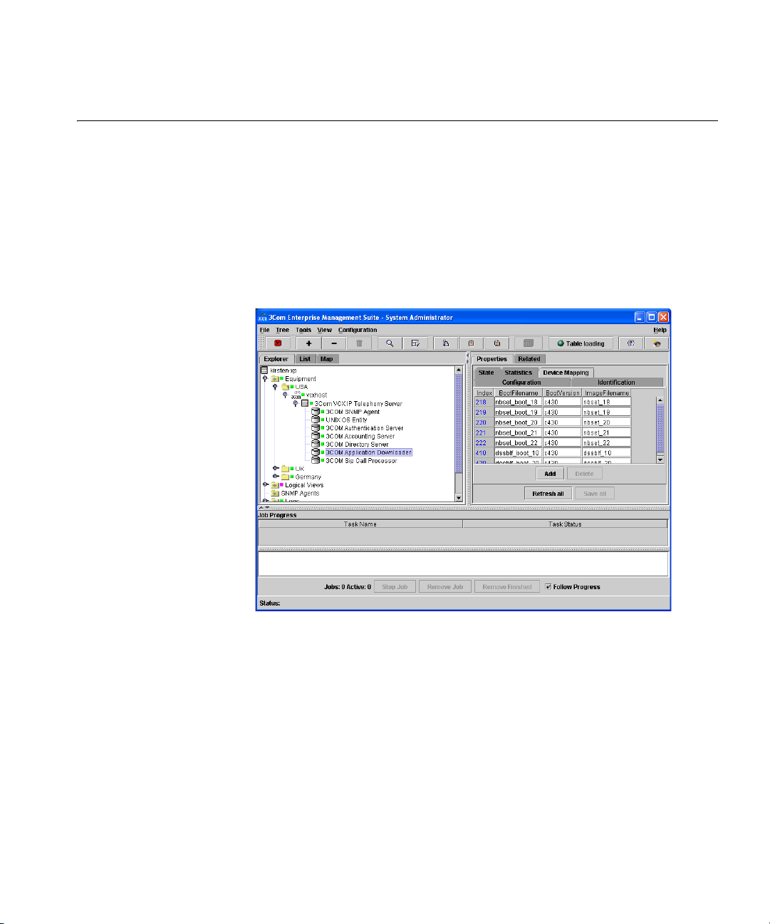
Device Mapping 73
Device Mapping The SIP Phone Downloader application comes with two images:
ndset_boot_19 and nbset_19, and the boot version is a508. All images
need to be stored in the $HOME/sipdl/images.
To configure the device mapping:
1 Launch EMS and discover the server that the SIP Phone Downloader is
installed on. The navigation tree looks similar to Figure 2.
Figure 2 SIP Phone Downloader Device Mapping Tab
2 Click 3Com Application Downloader.
3 From the Properties tabs, click Device Mapping.
4 Set the following attributes by double-clicking each field:
■ BootFilename — SIP phone downloader code and firmware code
provided by the NBX phone. This value should be set to
nbset_boot_19.
■ BootVersion — Version of the firmware code. This value should be
set to a508.
■ ImageFilename — Application code and SIP Phone application. This
value should be set to nbset_19.
5 Click Save all.
Page 74

74 CHAPTER 6: CONFIGURING THE SIP PHONE DOWNLOADER
SIP Phone Downloader Maintenance
Restarting the
Application
Downloader
Stopping the
Application
Downloader
Verifying the
Application
Downloader State
This section provides maintenance tasks that are specific to just the
application downloader.
To restart the application downloader:
1 From the EMS explorer tree, navigate to the 3Com Application
Downloader.
2 Right-click the application downloader and select Maintenance and then
click Hard Restart.
To stop the application downloader:
1 From the EMS explorer tree, navigate to the 3Com Application
Downloader.
2 Right-click the application downloader and select Maintenance and then
click Hard Shutdown.
To verify the state of the application downloader:
1 Login to EMS.
2 Navigate to the application downloader.
3 The status indicator light that appears next to the 3COM Application
Downloader identifies these states:
■ green — it is running
■ red — it is down
Page 75

CONFIGURING THE COMMON
7
Verifying State of the Common Agent
AGENT
The Common Agent is referred to as the SNMP Agent in EMS.
Use the State tab to view basic statistics for the common agent.
1 Log into EMS.
2 From the Explorer tab, navigate to the 3COM SNMP Agent.
3 From the Properties tab, click State.
4 For a description of each field, see Table 32.
Table 32 Common Agent State Tab
Attribute Description Settings
Operational State Indicates the current operational state. Read-only
Reserved Indicates if the object is reserved by another
user.
Reserved by Indicates who has reserved the object. Read-only
Software status The current operational state of the entity. If
AdminStatus is down, then OperStatus should
be down. If AdminStatus is changed to up,
through the entity command interface, then
OperStatus should change to up if the entity
is operational; it should remain in the down
state if and only if there is a fault that
prevents it from going to the up state; it
should remain in the notPresent state if the
entity has missing components. If the entity is
operational, but not responding to queries,
the state is notResponding.
Usage State Indicates how busy the resource is. Read-only
Read-only
Read-only
Page 76

76 CHAPTER 7: CONFIGURING THE COMMON AGENT
Verifying Common Agent Software Version
Common Agent Identification Tab
To verify what the common agent version is:
1 Log into EMS.
2 From the Explorer tab, navigate to the 3COM SNMP Agent.
3 From the Properties tab, click Identification.
4 From the Version field, the SNMP agent version is listed.
Use the Identification tab to view basic statistics for the common agent
such as the software version.
1 Log into EMS.
2 From the Explorer tab, navigate to the 3COM SNMP Agent.
3 From the Properties tab, click State.
4 For a description of each field, see Table 33.
Table 33 IP Messaging Identification Tab
Attribute Description Settings
Alias A management defined alias for the entity
saved across reboots.
Class The internal schema className for this
object.
FQN The fully qualified name of this object. This is
the complete path from the root of all
objects.
Last State Change The value of sysUpTime at the time the entity
entered its current operational state.
User Label A label assign by the user. String
Vendor The vendor name of this software. Read-only
Version The current version of this software. Read-only
String
Read-only
Read-only
Read-only
Page 77

Enabling Back-end Server Traps 77
Enabling Back-end Server Traps
Configuring Trap
Destinations
Back-end server traps can be enabled and disabled at the 3COM SNMP
Agent level.
Alarm notification requires two components: a device (the 3Com VCX IP
Telephony Server) to send traps and a device (an alarm server) to receive
them and alert the network manager. Traps are sent over the Simple
Network Management Protocol (SNMP), which runs on the User
Datagram Protocol / Internet Protocol (UDP/IP).
First, use Enterprise Management Suite to tell the 3Com VCX IP
Telephony Server where to send traps. Then use Enterprise Management
Suite to enable the traps. Finally, start the trap generation.
To configure a trap destination:
1 From the Explorer tab, select 3Com VCX IP Telephony Server to configure.
2 From the Properties tab, select Trap Destinations.
3 At the bottom of the right-hand pane, click Add.
The Add Row to Table dialog box opens.
4 Ty pe th e IP address and Community string for the trap destination.
5 Click OK.
Enabling Back-end
Server Traps
The Trap Destinations tab changes to show the new trap destination.
The 3Com VCX IP Telephony Server can generate traps when the
authentication server changes state.
To enable back-end server traps:
1 From the Explorer tab, click 3Com VCX IP Telephony Server to configure.
2 Select the 3COM SNMP Agent element.
3 From the Properties tab, select Trap Configurations.
Figure 3 shows the location for all back-end server traps.
Page 78

78 CHAPTER 7: CONFIGURING THE COMMON AGENT
Figure 3 Enabling Back-end Server Traps
4 Enable and disable SNMP traps according to your customized needs.
5 Click Save all.
6 Back up the server configuration.
Receiving Traps To start and stop receiving SNMP traps:
1 From the Explorer tab, right-click 3Com VCX IP Telephony Server.
2 From the pop-up menu, select Tr ap s.
From the pop-up menu, select Start receiving to begin receiving SNMP
traps or Stop receiving to stop receiving SNMP traps.
Page 79

Common Agent Maintenance 79
Common Agent Maintenance
Restarting the
Common Agent
Verifying the
Common Agent State
This section provides maintenance tasks that are specific to just the
Common Agent.
To restart the Common Agent:
1 From the EMS explorer tree, navigate to the 3Com SNMP Agent.
2 Right-click the SNMP Agent and select Maintenance and then click Hard
Restart.
To verify the state of the Common Agent:
1 Login to EMS.
2 Navigate to the SNMP Agent.
3 The status indicator light that appears next to the 3Com SNMP Agent
identifies these states:
■ green — it is running
■ red — it is down
Page 80

80 CHAPTER 7: CONFIGURING THE COMMON AGENT
Page 81

8
CONFIGURING THE OS ENTITY
The 3Com Convergence Applications Suite is built on 3Com Linux. This
chapter provides details on how to verify the O/S version a server is built
on and whether or not it is operational.
Verifying State of the O/S
Use the State tab to view basic statistics for the operating system.
1 Log into EMS.
2 From the Explorer tab, navigate to the UNIX OS Entity.
3 From the Properties tab, click State.
4 For a description of each field, see Table 34.
Table 34 O/S Entity State Tab
Attribute Description Settings
Operational State Indicates the current operational state. Read-only
Reserved Indicates if the object is reserved by another
user.
Reserved by Indicates who has reserved the object. Read-only
Software status The current operational state of the entity. If
AdminStatus is down, then OperStatus should
be down. If AdminStatus is changed to up,
through the entity command interface, then
OperStatus should change to up if the entity
is operational; it should remain in the down
state if and only if there is a fault that
prevents it from going to the up state; it
should remain in the notPresent state if the
entity has missing components. If the entity is
operational, but not responding to queries,
the state is notResponding.
Usage State Indicates how busy the resource is. Read-only
Read-only
Read-only
Page 82

82 CHAPTER 8: CONFIGURING THE OS ENTITY
Verifying O/S Software Version
O/S Identification Ta b
To verify what the operating system version is:
1 Log into EMS.
2 From the Explorer tab, navigate to the UNIX OS Entity.
3 From the Properties tab, click Identification.
4 From the Version field, the O/S version is listed.
Use the Identification tab to view basic statistics for the operating system
such as the software version.
1 Log into EMS.
2 From the Explorer tab, navigate to the UNIX OS Entity.
3 From the Properties tab, click State.
4 For a description of each field, see Table 35.
Table 35 IP Messaging Identification Tab
Attribute Description Settings
Alias A management defined alias for the entity
saved across reboots.
Class The internal schema className for this
object.
FQN The fully qualified name of this object. This is
the complete path from the root of all
objects.
Last State Change The value of sysUpTime at the time the entity
entered its current operational state.
User Label A label assign by the user. String
Vendor The vendor name of this software. Read-only
Version The current version of this software. Read-only
String
Read-only
Read-only
Read-only
Page 83

O/S Entity Maintenance 83
O/S Entity Maintenance
Gracefully Restarting
the O/S Entity
Verifying the O/S
Entity State
This section provides maintenance tasks that are specific to just the O/S
Entity.
To gracefully restart the O/S Entity:
1 From the EMS explorer tree, navigate to the UNIX OS Entity.
2 Right-click the O/S Entity and select Maintenance and then click Hard
Restart.
To verify the state of the O/S Entity:
1 Login to EMS.
2 Navigate to the O/S Entity.
3 The status indicator light that appears next to the UNIX OS Entity
identifies these states:
■ green — it is running
■ red — it is down
Page 84

84 CHAPTER 8: CONFIGURING THE OS ENTITY
Page 85

UPGRADING AND MAINTAINING
9
VCX SYSTEMS AND COMPONENTS
This chapter provides details on how to remotely upgrade your VCX
systems and/or components using EMS. It also explains how to maintain
versions of VCX on your system, including viewing installed versions and
removing unused versions of VCX.
Sections in this chapter include:
■ Maintaining VCX Versions
■ Upgrading VCX Server Software from 7.0 to 7.1
■ Upgrading VCX Server Software from 6.0x to 7.0
To upgrade VCX Server Software from 7.1x to 7.1y, follow the
instructions in Upgrading VCX Server Software from 7.0 to 7.1
CAUTION: 3Com Corporation strongly recommends that you backup
your VCX system before you perform an upgrade. See Creating Backup
Configuration Files for instructions. If the upgrade fails and you must
downgrade, you can restore data from these backups as part of the
downgrade procedure.
.
Page 86
86 CHAPTER 9: UPGRADING AND MAINTAINING VCX SYSTEMS AND COMPONENTS
Maintaining VCX Versions
Viewing Installed
Versions of VCX
Removing an Unused
Version of VCX
EMS allows you to view all of the installed versions of VCX on your
system, and lets you remove old, unused versions of VCX.
You will need to view and verify the versions of VCX installed on your
system before you perform an upgrade.
To view all of the installed versions of VCX on your system:
1 From the EMS client Explorer tree, navigate to 3Com VCX IP Telephony
Server.
2 From the right-hand pane, click the Installed Software Versions tab.
All of the versions installed on your system appear, with the date of
installation, version number, and version state.
You cannot remove a currently active version of VCX from your system.
To remove an unused version of VCX from your system:
1 From the EMS client Explorer tree, navigate to 3Com VCX IP Telephony
Server.
2 In the right-hand pane, click the Planned Upgrades tab.
3 In the Software Version To Be Removed field, select the VCX version to be
removed from the drop-down list. The drop-down list displays all of the
installed VCX versions on the server.
You can remove unused versions of VCX only. You cannot remove a
currently active VCX version.
4 Click Save all to save the version to be removed.
5 From the Explorer tab, right-click 3Com VCX IP Telephony Server.
6 From the pop-up menu, select Install Upgrade Images and then select
Remove Installed Version.
The version of VCX is removed from your system.
Page 87

Upgrading VCX Server Software from 7.0 to 7.1 87
Upgrading VCX Server Software from 7.0 to 7.1
This section describes the procedures required to upgrade a system
running VCX server software version 7.0 to VCX server software
version 7.1.These procedures upgrade the VCX system to an operational
state and assumes the VCX system was operational prior to the upgrade
occurring.
EMS does not allow individual component upgrades without first
installing a new version for switchover. However, individual component
upgrades can be performed without first installing a new version for
switchover through the CLI interface.
These instructions can also be used for upgrading from version 7.1x to
7.1y.
This section assumes the VCX system is successfully operating at version
7.0.7c before you perform the upgrade. If your system is running an
earlier version of VCX 7.0 software (or VCX 6.0 software), you must
upgrade to 7.0.7c before upgrading to version 7.1. See V
iewing Installed
Versions of VCX for instructions on verifying the version of VCX installed
on your system. See Upgrading a Multiple Site Configuration from 6.0.x
to 7.0 for instructions on upgrading from 6.0 to 7.0.
This section covers the following configurations and/or components that
can be upgraded using EMS:
■ Upgrading a Multiple Site Configuration from 7.0 to 7.1
■ Upgrading the VCX IP Telephony Software from 7.0 to 7.1
■ Installing IP Messaging Software Patch Release
■ Installing SIP Phone Downloader and Boot File Software Patch
Releases
The components in a multi-site VCX system can be set up in many
possible configurations. The procedures in this section describe
upgrading a multi-site VCX system that includes two regions (Region 1
and Region 2) with multiple branch offices in each region. For instructions
on upgrading a VCX system with other configurations (such as single-site
systems with two or four servers, or multi-site systems with no branch
offices), see the VCX Maintenance Guide.
Page 88

88 CHAPTER 9: UPGRADING AND MAINTAINING VCX SYSTEMS AND COMPONENTS
Upgrading a Multiple
Site Configuration
from 7.0 to 7.1
This section describes how to upgrade a VCX configuration from version
7.0 to 7.1 where there is more than one regional office and branch
offices present.
EMS does not allow individual component upgrades without first
installing a new version for switchover. However, individual component
upgrades can be performed without first installing a new version for
switchover through the CLI interface.
These instructions assume a two-region office configuration where the
regional offices use global messaging and the branch offices use local
messaging configurations. When upgrading a region-to-region office
configuration, replication needs to be dropped.
Multiple Site Upgrade Order
When upgrading a multiple site configuration keep this order in mind,
which is outlined in more detail in the actual procedure:
■ First, upgrade the replicated regional office VCX data servers.
■ Second, upgrade the regional office IP Messaging servers.
■ Third, upgrade the regional office Call Processing server.
■ Fourth, upgrade the branch offices, starting with any that are hosted
by the primary regional office.
Upgrade Instructions
The software upgrade package is provided by 3Com or your authorized
3Com reseller and must be installed using the following sequence of
steps.
1 Copy the upgrade tar file(s) to the EMS server in the
<EMS_INSTALL_DIR>/software_upgrades/voice/SystemUpgrades
directory. This includes any software for the VCX data server, IP
Messaging server, and/or the VCX call processing server.
2 If you have a replicated system, clear any replication errors before
performing an upgrade, otherwise, go to step 3
.
a From the EMS client explorer tree, for each VCX data server you want
to drop replication from, click 3Com VCX IP Telephony Server.
b Right-click 3Com VCX IP Telephony Server, select Database
Replication, and then click Clear Replication Errors.
Page 89

Upgrading VCX Server Software from 7.0 to 7.1 89
If the Clear Replication Errors option is greyed out, make sure the
Replication Settings tab is populated.
You can only delete replication errors on regional offices, not on branch
offices.
3 Stop Tomcat on the region 1 and 2 VCX call processing server.
a From the EMS client explorer tree, for the region 1 VCX call processing
server, click 3Com VCX IP Telephony Server.
b Right-click 3Com VCX IP Telephony Server, select Web Provisioning,
and then click Disable Web Provisioning.
c From the EMS client explorer tree, for the region 2 VCX call processing
server, click 3Com VCX IP Telephony Server.
d Right-click 3Com VCX IP Telephony Server, select Web Provisioning,
and then click Disable Web Provisioning.
4 Stop replication between the region 1 and 2 VCX data servers.
a From the EMS client explorer tree, for the region 1 VCX data server,
click 3Com VCX IP Telephony Server.
b Right-click 3Com VCX IP Telephony Server, select Database
Replication, and then click Drop Replication.
5 Upgrade the region 1 VCX data server.
a From the EMS client explorer tree, for the region 1 VCX data server,
click 3Com VCX IP Telephony Server.
b From the right-hand of the pane, click the Planned Upgrades tab.
For each of these fields, the default setting is None Planned.
c Double-click the Planned System Upgrade field and click the
vcx-dataserver-<version>.tar file from the drop-down menu.
d Click Save all to commit the filename to the database.
Once an upgrade file has been selected, the file must be transferred to
the server.
e To transfer the file to the server, from the VCX data server 3Com VCX
IP Telephony Server right-click menu, click Transfer Upgrade Images
and then click Transfer System Upgrade File.
These options are only available is a file has been selected for upgrade.
The file is SFTP'd to the server, using the SFTP credentials in the
SSH/SFTP Settings tab.
Now the upgrade file needs to be installed.
Page 90

90 CHAPTER 9: UPGRADING AND MAINTAINING VCX SYSTEMS AND COMPONENTS
With IP Telephony upgrades, this only unpacks the tar file and creates
the relevant directories on the server, it does not
version to the new version.
f To install the upgrade file to the server, from the VCX data server
3Com VCX IP Telephony Server right-click menu, click Install Upgrade
Images and then click Install System Upgrade.
g Verify that the upgrade succeeded. To verify that the upgrade
succeeded, the VCX data server 3Com VCX IP Telephony Server
right-click menu, click Install Upgrade Images and then click Verify
Upgrade.
h Switch the software version for the VCX data server. A switchover
needs to be performed before
the new version takes effect.
i To switchover the VCX data server software, right-click the 3Com VCX
IP Telephony Server in the left pane of the EMS window, click Install
Upgrade Images and then click Switchover Version.
You may have to wait a few seconds for the Install Upgrade Images menu
to appear.
The server reboots and EMS provides status of the switchover
progress.
switch the running
■ If the switchover is successful, you must change the Operational
State from degraded to enabled. To do this, right-click the 3Com
VCX IP Telephony Server, click State, and then Update. The
Operational State is changed to enabled. Go to step g
■ If the switchover is not successful and you receive the error
to continue.
message Error: failed, vcxUpgradeNewConfigFileNeeded, you must
create a new configuration file. To create the new configuration
file:
a Log in as root on the VCX server on which the switch failed and
enter these commands:
cd /opt/3com/VCX.<NewReleaseInstalled>/conf
vcx-updatecfg
b Enter the number that corresponds to the VCX version to which
you are upgrading.
c Press the Return key to specify the configuration file from the
currently active VCX version.
d When prompted for a configuration file name, enter
VCXConfiguration.xml.
Page 91

Upgrading VCX Server Software from 7.0 to 7.1 91
e Answer the questions appropriately for the server being
upgraded.
f Perform the Install Upgrade Images > Switchover Version
command again, as described previously in step i.
g To verify the version numbers of the newly installed software, click
each component from the explorer tree and click the Identification
tab.
h Click Refresh all to confirm that the latest software has been installed.
The software versions displayed for a single server may differ from each
other. To correct this and make sure you are viewing the latest values,
click Refresh all.
6 Stop the region 1 VCX data server before upgrading the region 2 VCX
data server.
a From the EMS client explorer tree, for the region 1 VCX data server,
click 3Com VCX IP Telephony Server.
b Expand 3Com VCX IP Telephony Server, and click 3Com VCX Data
Server.
c Right-click 3Com VCX Data Server, select Maintenance, and then click
Hard Shutdown.
7 Stop replication between the region 2 and 1 VCX data servers.
a From the EMS client explorer tree, for the region 2 VCX data server,
click 3Com VCX IP Telephony Server.
b Right-click 3Com VCX IP Telephony Server, select Database
Replication, and then click Drop Replication.
8 Upgrade the region 2 VCX data server. Repeat step a
except perform the steps on the region 2 VCX data server.
step 5
through step j in
9 Stop the region 2 VCX data server.
a From the EMS client explorer tree, for the region 2 VCX data server,
click 3Com VCX IP Telephony Server.
b Expand 3Com VCX IP Telephony Server, and click 3Com VCX Data
Server.
c Right-click 3Com VCX Data Server, select Maintenance, and then click
Hard Shutdown.
10 Upgrade the region 2 VCX data server database on region 1.
Page 92

92 CHAPTER 9: UPGRADING AND MAINTAINING VCX SYSTEMS AND COMPONENTS
a From the EMS client explorer tree, for the region 1 VCX data server,
click 3Com VCX IP Telephony Server.
b From the right-hand pane, click the DB Schema Upgrade tab.
c From the Database Schema Site ID field, enter the Region 2 site ID.
d Click Save All.
e Click the 3Com VCX IP Telephony Server for the region 2 VCX data
server.
f Right-click 3Com VCX IP Telephony Server, and select Database
Upgrade, and then click Upgrade Database Schema.
11 Upgrade the region 1 VCX data server database on region 2.
a From the EMS client explorer tree, for the region 2 VCX data server,
click 3Com VCX IP Telephony Server.
b From the right-hand pane, click the DB Schema Upgrade tab.
c From the Database Schema Site ID field, enter the Region 1 site ID.
d Click Save All.
e Click the 3Com VCX IP Telephony Server for the region 1 VCX data
server.
f Right-click 3Com VCX IP Telephony Server, and select Database
Upgrade, and then click Upgrade Database Schema.
12 Setup replication for the region 1 VCX data server.
a From the EMS client explorer tree, for the region 1 VCX data server,
click 3Com VCX IP Telephony Server.
b In the right-hand pane, click the Replication Settings tab.
c From the Master Def Site IP Address field, enter the IP Address of the
master definition site (usually the region 1 primary VCX data server).
d From the Master Site IP Address field, enter the IP Address of the
master site (usually the region 2 primary VCX data server).
e From the Site ID field, enter the site ID of the Region 1 VCX data
server.
f Click Save All.
Right-click 3Com VCX IP Telephony Server, select Database
g
Replication, and then click Setup Database Replication.
13 Setup replication for the region 2 VCX data server.
Page 93

Upgrading VCX Server Software from 7.0 to 7.1 93
a From the EMS client explorer tree, for the region 2 VCX data server,
click 3Com VCX IP Telephony Server.
b In the right-hand pane, click the Replication Settings tab.
c From the Master Def Site IP Address field, enter the IP Address of the
master definition site (usually the region 2 primary VCX data server).
d From the Master Site IP Address field, enter the IP Address of the
master site (usually the region 1 primary VCX data server).
e From the Site ID field, enter the site ID of the Region 1 VCX data
server.
f Click Save All.
g Right-click 3Com VCX IP Telephony Server, select Database
Replication, and then click Setup Database Replication.
14 Start the Region 1 VCX data server. This cannot be done until the
replication setup is finished, which takes a minimum of 20 minutes.
To verify if the replication is finished, right-click 3Com VCX IP Telephony
Server of the VCX data server, select Database Replication, and then click
Check Database Replication. Once complete the Job Status pane of the
EMS client lists
Check Database Replication complete.
a From the EMS client explorer tree, for the region 1 VCX data server,
click 3Com VCX IP Telephony Server.
b Expand 3Com VCX IP Telephony Server, and click 3Com VCX Data
Server.
c Right-click 3Com VCX Data Server, select Maintenance, and then click
Hard Restart.
15 Start the Region 2 VCX data server. This cannot be done until the
replication setup is finish, which takes a minimum of 20 minutes.
To verify if the replication is finished, right-click 3Com VCX IP Telephony
Server of the VCX data server, select Database Replication, and then click
Check Database Replication. Once complete the Job Status pane of the
EMS client lists
Check Database Replication complete.
a From the EMS client explorer tree, for the region 2 VCX data server,
click 3Com VCX IP Telephony Server.
b Expand 3Com VCX IP Telephony Server, and click 3Com VCX Data
Server.
c Right-click 3Com VCX Data Server, select Maintenance, and then click
Hard Restart.
Page 94

94 CHAPTER 9: UPGRADING AND MAINTAINING VCX SYSTEMS AND COMPONENTS
16 Shut down the primary IP Messaging server.
a From the EMS client explorer tree, for the primary IP Messaging server,
click 3Com VCX IP Telephony Server.
b Expand 3Com VCX IP Telephony Server, and click 3Com IP Messaging
System.
c Right-click 3Com IP Messaging System, select Maintenance, and then
click Graceful Shutdown.
17 Shut down the secondary IP Messaging server.
a From the EMS client explorer tree, for the secondary IP Messaging
server, click 3Com VCX IP Telephony Server.
b Expand 3Com VCX IP Telephony Server, and click 3Com IP Messaging
System.
c Right-click 3Com IP Messaging System, select Maintenance, and then
click Graceful Shutdown.
18 Upgrade the primary IP Messaging server.
a From the EMS client explorer tree, for the primary IP Messaging server,
click 3Com VCX IP Telephony Server.
b In the right-hand pane, click the Planned Upgrades tab.
c Double-click the Planned System Upgrade field and click the
vcx-ipmsg-<version>.tar file from the drop-down menu.
d Click Save all to commit the tar file to the database.
Once an upgrade tar file has been selected, the tar file must be
transferred to the IP Messaging server.
e To transfer the tar file to the server, from the 3Com VCX IP Telephony
Server right-click menu, select Transfer Upgrade Images, and then
click Transfer System Upgrade File.
f These options are only available if a file has been selected for upgrade.
The file is transferred to the server using the SFTP credentials in the
SSH/SFTP Settings tab.
Next the upgrade tar file needs to be installed, which is the last step
before the new version becomes active.
g To install the upgrade file on the IP Messaging server, for the primary
IP Messaging server, click 3Com VCX IP Telephony Server.
h Right-click the 3Com VCX IP Telephony Server, select Install Upgrade
Images, and then click Install System Upgrade
.
Page 95

Upgrading VCX Server Software from 7.0 to 7.1 95
i To verify the version number of the newly installed software, click the
IP Messaging server from the explorer tree and then click the
Identification tab.
j Click Refresh all to confirm that the latest software has been installed.
19 Stop the primary IP Messaging server.
a From the EMS client explorer tree, for the primary IP Messaging server,
click 3Com VCX IP Telephony Server.
b Expand 3Com VCX IP Telephony Server, and click 3Com IP Messaging
System.
c Right-click 3Com IP Messaging System, select Maintenance, and then
click Graceful Shutdown.
20 Upgrade the secondary IP Messaging server.
a From the EMS client explorer tree, for the secondary IP Messaging
server, click 3Com VCX IP Telephony Server.
b In the right-hand pane, click the Planned Upgrades tab.
c Double-click the Planned System Upgrade field and click the
vcx-ipmsg-<version>.tar file from the drop-down menu.
d Click Save all to commit the tar file to the database.
Once an upgrade tar file has been selected, the tar file must be
transferred to the IP Messaging server.
e To transfer the tar file to the server, from the 3Com VCX IP Telephony
Server right-click menu, select Transfer Upgrade Images, and then
click Transfer System Upgrade File.
f These options are only available if a file has been selected for upgrade.
The file is transferred to the server using the SFTP credentials in the
SSH/SFTP Settings tab.
Next the upgrade tar file needs to be installed, which is the last step
before the new version becomes active.
g To install the upgrade file on the IP Messaging server, for the
secondary IP Messaging server, click 3Com VCX IP Telephony Server.
h Right-click the 3Com VCX IP Telephony Server, select Install Upgrade
Images, and then click Install System Upgrade.
i To verify the version number of the newly installed software, click the
IP Messaging server from the explorer tree and then click the
Identification tab.
Page 96

96 CHAPTER 9: UPGRADING AND MAINTAINING VCX SYSTEMS AND COMPONENTS
j Click Refresh all to confirm that the latest software has been installed.
21 Restart the primary IP Messaging server.
a From the EMS client explorer tree, for the primary IP Messaging server,
click 3Com VCX IP Telephony Server.
b Expand 3Com VCX IP Telephony Server, and click 3Com IP Messaging
System.
c Right-click 3Com IP Messaging System, select Maintenance, and then
click Graceful Restart.
22 Upgrade the primary VCX call processing server.
a From the EMS client explorer tree, for the primary VCX call processing
server, click 3Com VCX IP Telephony Server.
b In the right-hand pane, click the Planned Upgrades tab.
c Double-click the Planned System Upgrade field and click the
vcx-callserver-<version>.tar file from the drop-down menu.
d Click Save all to commit the tar file to the database.
Once an upgrade tar file has been selected, the tar file must be
transferred to the VCX calling processing server.
e To transfer the tar file to the server, from the 3Com VCX IP Telephony
Server right-click menu, select Transfer Upgrade Images, and then
click Transfer System Upgrade File.
f These options are only available if a file has been selected for upgrade.
The file is transferred to the server using the SFTP credentials in the
SSH/SFTP Settings tab.
Next the upgrade tar file needs to be installed, which is the last step
before the new version becomes active.
g To install the upgrade file on the VCX calling processing server, for the
primary VCX calling processing server, click 3Com VCX IP Telephony
Server.
h Right-click the 3Com VCX IP Telephony Server, select Install Upgrade
Images, and then click Install System Upgrade.
i To verify the version number of the newly installed software, from the
explorer tree, for the primary VCX call processing server, click 3Com
VCX IP Telephony Server.
j In the left hand pane, click the Identification tab.
k Click Refresh all to confirm that the latest software has been installed.
Page 97

Upgrading VCX Server Software from 7.0 to 7.1 97
23 Upgrade the secondary VCX call processing server.
a From the EMS client explorer tree, for the secondary VCX call
processing server, click 3Com VCX IP Telephony Server.
b In the right-hand pane, click the Planned Upgrades tab.
c Double-click the Planned System Upgrade field and click the
vcx-callserver-<version>.tar file from the drop-down menu.
d Click Save all to commit the tar file to the database.
Once an upgrade tar file has been selected, the tar file must be
transferred to the VCX calling processing server.
e To transfer the tar file to the server, from the 3Com VCX IP Telephony
Server right-click menu, select Transfer Upgrade Images, and then
click Transfer System Upgrade File.
f These options are only available if a file has been selected for upgrade.
The file is transferred to the server using the SFTP credentials in the
SSH/SFTP Settings tab.
Next the upgrade tar file needs to be installed, which is the last step
before the new version becomes active.
g To install the upgrade file on the VCX calling processing server, for the
secondary VCX calling processing server, click 3Com VCX IP Telephony
Server.
h Right-click the 3Com VCX IP Telephony Server, select Install Upgrade
Images, and then click Install System Upgrade.
i To verify the version number of the newly installed software, from the
explorer tree, for the secondary VCX call processing server, click 3Com
VCX IP Telephony Server.
j In the left hand pane, click the Identification tab.
k Click Refresh all to confirm that the latest software has been installed.
24 Upgrade the Billing Support server.
a From the EMS client explorer tree, for the server where the billing
support server is installed, click 3Com VCX IP Telephony Server.
b In the right-hand pane, click the Planned Upgrades tab.
c Double-click the Planned System Upgrade field and click the
vcx-bss-<version>.tar file from the drop-down menu.
d Click Save all to commit the tar file to the database.
Page 98

98 CHAPTER 9: UPGRADING AND MAINTAINING VCX SYSTEMS AND COMPONENTS
Once an upgrade tar file has been selected, the tar file must be
transferred to the billing support server.
e To transfer the tar file to the server, from the 3Com VCX IP Telephony
Server right-click menu, select Transfer Upgrade Images, and then
click Transfer System Upgrade File.
f These options are only available if a file has been selected for upgrade.
The file is transferred to the server using the SFTP credentials in the
SSH/SFTP Settings tab.
Next the upgrade tar file needs to be installed, which is the last step
before the new version becomes active.
g To install the upgrade file on the billing support server, click 3Com
VCX IP Telephony Server.
h Right-click the 3Com VCX IP Telephony Server, select Install Upgrade
Images, and then click Install System Upgrade.
25 Upgrade the branch office(s), starting with any that are a part of
Region 1.
a Stop Tomcat on the host VCX call processing server.
b From the EMS client explorer tree, for the host VCX call processing
server, click 3Com VCX IP Telephony Server.
c Right-click 3Com VCX IP Telephony Server, select Web Provisioning,
and then click Disable Web Provisioning.
■ To upgrade an IP Telephony Server branch office go to step 26 on
page 116
■ To upgrade an IP Telephony Server and IP Messaging Server branch
office go to step 27
.
on page 116.
26 Upgrade an IP Telephony Server branch office (Soft Switch).
a From the EMS client explorer tree, for the branch office, click 3Com
VCX IP Telephony Server.
b In the right-hand pane, click the Planned Upgrades tab.
c Double-click the Planned System Upgrade field and click the
vcx-softswitch<version>.tar file from the drop-down menu.
d Click Save all to commit the tar file to the database.
Once an upgrade tar file has been selected, the tar file must be
transferred to the branch office server.
Page 99

Upgrading VCX Server Software from 7.0 to 7.1 99
e To transfer the tar file to the server, from the 3Com VCX IP Telephony
Server right-click menu, select Transfer Upgrade Images, and then
click Transfer System Upgrade File.
f These options are only available if a file has been selected for upgrade.
The file is transferred to the server using the SFTP credentials in the
SSH/SFTP Settings tab.
Next the upgrade tar file needs to be installed, which is the last step
before the new version becomes active.
g To install the upgrade file on the branch office server, for the branch
office server, click 3Com VCX IP Telephony Server.
h Right-click the 3Com VCX IP Telephony Server, select Install Upgrade
Images, and then click Install System Upgrade.
i To verify the version number of the newly installed software, from the
explorer tree, for the branch office server, click 3Com VCX IP
Telephony Server.
j In the left hand pane, click the Identification tab.
k Click Refresh all to confirm that the latest software has been installed.
If you have another branch office to upgrade in this region, go to
step 25
on page 115.
If this is the last branch office to upgrade for this region, go to step 28
on page 117
.
27 Upgrade an IP Telephony Server and IP Messaging branch office (All in
One Server).
a From the EMS client explorer tree, for the branch office, click 3Com
VCX IP Telephony Server.
b In the right-hand pane, click the Planned Upgrades tab.
c Double-click the Planned System Upgrade field and click the
vcx-all-<version>.tar file from the drop-down menu.
d Click Save all to commit the tar file to the database.
Once an upgrade tar file has been selected, the tar file must be
transferred to the branch office server.
e To transfer the tar file to the server, from the 3Com VCX IP Telephony
Server right-click menu, select Transfer Upgrade Images, and then
click Transfer System Upgrade File.
Page 100

100 CHAPTER 9: UPGRADING AND MAINTAINING VCX SYSTEMS AND COMPONENTS
f These options are only available if a file has been selected for upgrade.
The file is transferred to the server using the SFTP credentials in the
SSH/SFTP Settings tab.
Next the upgrade tar file needs to be installed, which is the last step
before the new version becomes active.
g To install the upgrade file on the branch office server, for the branch
office server, click 3Com VCX IP Telephony Server.
h Right-click the 3Com VCX IP Telephony Server, select Install Upgrade
Images, and then click Install System Upgrade.
i To verify the version number of the newly installed software, from the
explorer tree, for the branch office server, click 3Com VCX IP
Telephony Server.
j In the left hand pane, click the Identification tab.
k Click Refresh all to confirm that the latest software has been installed.
If you have another branch office to upgrade in this region, go to
step 25
on page 115.
If this is the last branch office to upgrade for this region, go to step 28
on page 117
.
28 Restart Tomcat on the host regional office VCX call processing server.
a From the EMS client explorer tree, for the host VCX call processing
server, click 3Com VCX IP Telephony Server.
b Right-click 3Com VCX IP Telephony Server, select Web Provisioning,
and then click Enable Web Provisioning.
If you have another branch office to upgrade in a different region, go
to step 25
on page 115.
If you have no more branch offices to upgrade, the upgrade is complete.
 Loading...