

Page 1

New Installation for
®
NETBuilder II
Software version 10.1
®
Software
http://www.3com.com/
Part No. 09-1324-000
Published October 1997
Page 2

ii
3Com Corporation
Bayfront Plaza
Clara, California
■
Santa
■
95052-8145
■
5400
© 3Com Corporation, 1997. All rights reserved. No part of this documentation may be reproduced in any
form or by any means or used to make any derivative work (such as translation, transformation, or
adaptation) without permission from 3Com Corporation.
3Com Corporation reserves the right to revise this documentation and to make changes in content from
time to time without obligation on the part of 3Com Corporation to provide notification of such revision
or change.
3Com Corporation provides this documentation without warranty of any kind, either implied or
expressed, including, but not limited to, the implied warranties of merchantability and fitness for a
particular purpose. 3Com may make improvements or changes in the product(s) and/or the program(s)
described in this documentation at any time.
UNITED STATES GOVERNMENT LEGENDS:
If you are a United States government agency, then this documentation and the software described
herein are provided to you subject to the following restricted rights:
For units of the Department of Defense:
Restricted Rights Legend: Use, duplication or disclosure by the Government is subject to restrictions as set
forth in subparagraph (c) (1) (ii) for restricted Rights in Technical Data and Computer Software clause at
48 C.F.R. 52.227-7013. 3Com Corporation, 5400 Bayfront Plaza, Santa Clara, California 95052-8145.
For civilian agencies:
Restricted Rights Legend: Use, reproduction or disclosure is subject to restrictions set forth in
subparagraph (a) through (d) of the Commercial Computer Software - Restricted Rights Clause at 48
C.F.R. 52.227-19 and the limitations set forth in 3Com Corporation’s standard commercial agreement for
the software. Unpublished rights reserved under the copyright laws of the United States.
If there is any software on removable media described in this documentation, it is furnished under a
license agreement included with the product as a separate document, in the hard copy documentation,
or on the removable media in a directory file named LICENSE.TXT. If you are unable to locate a copy,
please contact 3Com and a copy will be provided to you.
Unless otherwise indicated, 3Com registered trademarks are registered in the United States and may or
may not be registered in other countries.
3Com, NETBuilder, NETBuilder II, and Transcend are registered trademarks of 3Com Corporation. 3TECH
is a trademark of 3Com Corporation. 3ComFacts is a service mark of 3Com Corporation.
CompuServe is a registered trademark of CompuServe, Inc. The Sun logo is a registered trademark of Sun
Microsystems, Inc. Solaris is a registered trademark and SunOS and SPARC are trademarks of Sun
Microsystems, Inc. Xerox is a trademark of Xerox Corporation. UNIX is a registered trademark in the
United States and other countries, licensed exclusively through X/Open Company, Ltd. AppleTalk and
Macintosh are registered trademarks of Apple Corporation, Inc. VINES and Banyan are registered
trademarks of Banyan Systems. Novell and LAN WorkPlace are registered trademarks of Novell, Inc.
Windows is a registered trademark of Microsoft Corporation. NetManage is a registered trademark and
Chameleon is a trademark of NetManage, Inc. FTP Software and PC/TCP are registered trademarks of FTP
Software, Inc. Distinct is a registered trademark and TCP/IP Tools is a trademark of Distinct Corporation.
Other brand and product names may be registered trademarks or trademarks of their respective holders.
Guide written, illustrated, and produced by Debra Knodel and edited by Amy Guzules.
Printed on recycled paper.
Page 3

C
ONTENTS
A
Introduction 1
How to Use This Guide 1
Conventions 2
1
O
NETBuilder II Systems 1-1
Software 1-2
Installation Checklists 1-2
I
2
NSTALLING
A
Installing Software and Performing Initial Boot 2-1
Booting from the Flash Memory Card 2-1
Making a Backup of the Flash Memory Card 2-2
Using the Backup Flash Card 2-3
T
BOUT
VERVIEW
EZBuilt Preassembled NETBuilder II System 1-1
Component System 1-1
NETBuilder II Chassis with a DPE Module 1-1
NETBuilder II Chassis with a CEC 20 Module 1-1
NETBuilder II Systems with a DPE Module 1-3
NETBuilder II Systems
with a CEC 20 Module 1-4
DPE NETB
Prerequisites 2-1
Booting an EZBuilt NETBuilder II System 2-1
Booting a Component NETBuilder II System 2-2
Prerequisites 2-2
Procedure 2-2
HIS
G
S
UIDE
OFTWARE
UILDER
II S
AND
YSTEM
B
OOTING
HANGING
C
3
DPE NETB
Using the Boot Command 3-1
Configuring the Primary Boot Source 3-2
Prerequisites 3-2
Procedure 3-2
4
I
NSTALLING
YSTEM
S
Installing Software and Performing Initial Boot 4-1
Booting from the Flash Memory Card 4-1
Prerequisites 4-1
Booting an EZBuilt NETBuilder II System 4-1
THE
B
UILDER
S
OFTWARE
OOT
II S
OURCE
S
YSTEM
AND
ON
B
OOTING
A
A
CEC 20 NETB
UILDER
II
iii
Page 4

Booting a Component NETBuilder II System 4-2
Installing Software from a Network Management Station 4-2
Setting Up the
UNIX-based Network Management Station 4-2
Prerequisites 4-2
Procedure 4-3
Setting Up the PC-based Network Management Station 4-5
Prerequisites 4-5
Procedure 4-5
Booting a
NETBuilder II Image over the Network 4-6
Procedure 4-7
Copying the Software to a Flash Memory Card 4-8
Configuring IP 4-8
Copying Software to the NETBuilder II Using TFTP 4-9
C
HANGING
5
CEC 20 S
Configuring the Primary Boot Source 5-1
Prerequisites 5-1
Procedure 5-1
ONFIGURING
6
C
Logging on to the System 6-1
Learning About the User Interface 6-2
Accessing the User Interface 6-2
Menu-Driven Versus Command-Line Interface 6-2
Using the Menu-Driven Interface 6-2
Using the Command-Line Interface 6-3
Command-Line Parameter Attributes 6-9
ISDN-Related Syntax Variation 6-11
Address Formats 6-12
Getting Help 6-16
Setting up IP Routing 6-16
iv
B
THE
YSTEM
ASIC
B
Full-Form Syntax 6-4
Abbreviated Syntax 6-5
Symbols 6-5
Full and Abbreviated Syntax Examples 6-6
Variations in Command Syntax 6-7
Entering Service Names in Command Lines 6-7
Determining the Display of Ports and Virtual Ports 6-7
Using Aliases 6-8
Command History Substitution 6-8
Privilege Level 6-9
Syntax for Assigning Values 6-10
Numeric Values 6-10
Names 6-10
Strings 6-10
Port and Path Naming Restrictions 6-11
Media Addresses 6-12
Network Layer Addresses 6-14
OOT
S
S
OURCE
ETTINGS
ON
A
Page 5

Storing Configuration Parameter Values 6-17
Obtaining Network Manager Privilege Level 6-17
Changing the Password 6-18
Setting the Time and Date 6-18
Setting System Administrator Information 6-19
Assigning Internet Addresses 6-20
Assigning Internet Addresses to a Bridge 6-20
Assigning Internet Addresses to a Router 6-21
Obtaining an Internet Address 6-21
Setting Up the Simple Network Management Protocol 6-22
Modifying SNMP Parameters 6-23
NETBuilder Security 6-23
Building Firewalls for Security 6-23
Security Commands and Parameters 6-24
What Next? 6-24
A
B
OOTING
Booting from a TFTP/FTP Server A-1
Installing NETBuilder Software on the UNIX-based Network Management
Station A-1
Installing
NETBuilder Software
on the UNIX NMS A-2
Setting Up a Unique Configuration File Directory on a TFTP/FTP Server A-3
Setting the Primary Boot Source A-3
More Boot Options A-4
What Next? A-5
T
B
ECHNICAL
Online Technical Services B-1
World Wide Web Site B-1
3Com Bulletin Board Service B-1
3ComFacts Automated Fax Service B-2
3ComForum on CompuServe Online Service B-2
Support from Your Network Supplier B-3
Support from 3Com B-3
Returning Products for Repair B-4
NETB
THE
Prerequisites A-1
S
UPPORT
Access by Analog Modem B-1
Access by Digital Modem B-2
UILDER
II CEC 20 S
YSTEM
FROM
THE
N
ETWORK
I
NDEX
3C
OM
C
ORPORATION
L
IMITED
W
ARRANTY
v
Page 6

Page 7

.
Introduction
Additional Information
A
BOUT
This guide describes how to get started with your new NETBuilder II
bridge/router. It describes how to install NETBuilder software and perform the
initial system boot. It also explains how to access and use the command-line
interface to establish basic settings.
If you are upgrading software from an earlier version, refer to
NETBuilder Family Software
If the information in the release notes shipped with your product differs from the
information in this guide, follow the release notes.
Before you use the information in this guide, you must first install the
bridge/router according to your hardware installation guide
When you have completed the procedures in this guide, you will find valuable
information in
your software for bridging, routing, and wide area protocols, according to the
particular needs of your network. For a comprehensive description of NETBuilder
software commands, refer to
T
Using NETBuilder Family Software , which will help you configure
HIS
G
UIDE
Upgrading
.
Reference for NETBuilder Family Software .
®
Audience Description
How to Use This Guide
This guide is intended for network administrators who:
■
Have experience in planning, maintaining, and troubleshooting local or wide
area networks.
■
Are familiar with network protocols, bridging and routing, and network
management.
■
Will be responsible for configuring and operating NETBuilder II bridge/routers.
The chapters in this guide include the following information to help you install and
configure NETBuilder software:
■
Chapter 1 describes NETBuilder II systems that can use software version 10.1.
It also provides start-up checklists for systems with either a Dual Processor
Engine (DPE) module or a Communications Engine Card (CEC) 20 module.
Chapter 2 describes how to install software and boot a NETBuilder II system
■
with a DPE module.
Chapter 3 describes how to change the primary boot source on a NETBuilder II
■
system with a DPE module.
■ Chapter 4 describes how to install software and boot a NETBuilder II system
with a CEC 20 module. Several software installation options are described.
■ Chapter 5 describes how to change the primary boot source on a NETBuilder II
system with a CEC 20 module.
■ Chapter 6 describes how to log on to the system, obtain Network Manager
privileges, set passwords, time, date, and system administrator information,
assign Internet addresses, set NETBuilder security, and verify system operation.
Page 8
2 ABOUT THIS GUIDE
■ Appendix A describes how to boot a NETBuilder II system with a CEC 20 from
the network using TFTP and Appendix B has instructions on how to obtain
technical support.
Conventions Table 1 and Table 2 list conventions that are used throughout this guide.
Table 1 Notice Icons
Icon Notice Type Alerts you to...
Information note Important features or instructions
Caution Risk of personal safety, system damage, or loss of data
Warning Risk of severe personal injury
Table 2 Text Conventions
Convention Description
Syntax Evaluate the syntax provided and supply the appropriate values.
Commands Enter the command exactly as shown in text and press the Return or
Screen displays This typeface represents information as it appears on the screen.
The words “enter”
and “type”
[Key] names Key names appear in text in one of two ways:
Menu commands
and buttons
Words in italicized
type
Words in bold-face
type
Placeholders for values you must supply appear in angle brackets.
Example:
Enable RIPIP using:
SETDefault !<port> -RIPIP CONTrol = Listen
In this example, you must supply a port number for <port>.
Enter key. Example:
To remove the IP address, enter:
SETDefault !0 -IP NETaddr = 0.0.0.0
This guide always gives the full form of a command in uppercase and
lowercase letters. However, you can abbreviate commands by
entering only the uppercase letters and the appropriate value.
Commands are not case-sensitive.
When you see the word “enter” in this guide, you must type
something, and then press the Return or Enter key. Do not press the
Return or Enter key when an instruction simply says “type.”
■ Referred to by their labels, such as “the Return key” or “the
Escape key”
■ Written with brackets, such as [Return] or [Esc].
If you must press two or more keys simultaneously, the key names
are linked with a plus sign (+). Example:
Press [Ctrl]+[Alt]+[Del].
Menu commands or button names appear in italics. Example:
From the Help menu, select Contents.
Italics emphasize a point or denote new terms at the place where
they are defined in the text.
Bold text denotes key features.
Page 9

OVERVIEW
1
This chapter is an overview of how to get started with your new NETBuilder II
system. This chapter provides you with two checklists: one describes the basic
steps for starting a NETBuilder II system with a Dual Processor Engine (DPE)
module and the other describes the basic steps for starting a NETBuilder II system
with a Communication Engine Card (CEC) 20 module.
NETBuilder II Systems The NETBuilder II system consists of a 4-Slot, 8-Slot, or 8-Slot Extended chassis, the
main processor module (either a DPE or CEC 20), and NETBuilder II software.
Your new bridge/router is either an EZBuilt preassembled NETBuilder II system or a
NETBuilder II system that you have assembled from components.
EZBuilt Preassembled
NETBuilder II System
Component System If you have a NETBuilder II system that you have assembled yourself from
NETBuilder II Chassis
with a DPE Module
If you have an EZBuilt NETBuilder II system, it was preassembled before delivery.
This guide assumes that you have followed the instructions in the hardware
installation guide to:
■ Set up the system.
■ Attach the network and power cables.
■ Install a local terminal, PC (with a terminal emulation application), or modem to
the console port of the main processor module.
components, this guide assumes that you have followed the instructions in each
hardware installation manual to:
■ Install the system components.
■ Attach the network and power cables.
■ Install a local terminal, PC (with a terminal emulation application), or modem to
the console port of the main processor module.
The DPE module has two built-in flash memory drives. The upper drive is drive A,
and the lower drive is drive B. The DPE module does not support a floppy disk
drive or the flash drives used with the CEC 20 module.
NETBuilder II Chassis
with a CEC 20 Module
The CEC 20 module has an internal flash memory drive. The flash memory drive is
designated as drive A.
Page 10

1-2 CHAPTER 1: OVERVIEW
Software The NETBuilder software is available from 3Com on a preinstalled 20 MB flash
memory card or on CD-ROM. 3Com recommends that you buy the preinstalled
flash memory card.
Refer to the NETBuilder II Software Release Notes for information about the
different software packages that are available for your NETBuilder II system. The
procedures in this guide apply to all software packages.
Installation Checklists This section contains a checklist for installing software and booting a NETBuilder II
with a DPE module and a checklist for installing software and booting a
NETBuilder II with a CEC 20 module.
When using the checklists, refer to the chapters that apply to your system:
■ Chapter 2 and Chapter 3 apply only to NETBuilder II systems that have a DPE
module.
■ Chapter 4 and Chapter 5 apply only to NETBuilder II systems that have a CEC
20 module.
■ Chapter 6 applies to all NETBuilder II systems.
Page 11

Installation Checklists 1-3
NETBuilder II Systems
with a DPE Module
Use the following checklist to install software, boot, and configure basic settings
on a NETBuilder II system with a DPE module.
Install System Software and Boot — Refer to Chapter 2.
❑ Install software from a flash memory card.
Change the Primary Boot Source — Refer to Chapter 3
❑ Change the primary boot source default as needed.
Configure Basic Settings — Refer to Chapter 6.
❑ Log on to the system.
❑ Familiarize yourself with the command-line or menu-driven user interface (UI),
storing configuration parameter values, and getting help.
❑ Obtain Network Manager privilege level.
❑ Change the Network Manager password.
❑ Adjust the time and date if necessary. Time and date are preset and may need
to be adjusted for your time zone.
❑ Set system administrator information:
❑ System name and location
❑ System contact name and phone number
❑ Assign IP addresses/subnet masks to individual ports or one address to
the system.
❑ Set up the bridge/router for SNMP.
❑ Set up NETBuilder II system security.
❑ Use the Quick Installation Utility for further configuration.
Configure Specific Services for Your Network — Refer to Using NETBuilder
Family Software and Reference for NETBuilder Family Software.
Page 12

1-4 CHAPTER 1: OVERVIEW
NETBuilder II Systems
with a CEC 20 Module
Use the following checklist to install system software, boot the system, and
configure basic settings on a NETBuilder II system that has a CEC 20 module.
Install System Software and Boot — Refer to Chapter 4
❑
Select an installation option and proceed to appropriate installation section:
❑
Install software from flash memory card and boot the system.
or
❑
Install software from CD-ROM on UNIX or PC-based network management
station and boot the system.
Change the Primary Boot Source — Refer to Chapter 5
❑ Change the primary boot source default as needed.
Configure Basic Settings — Refer to Chapter 6
❑ Log on to the system.
❑ Familiarize yourself with the command-line or menu-driven user interface (UI),
storing configuration parameter values, and getting help.
❑ Obtain Network Manager privilege level.
❑ Change the Network Manager password.
❑ Adjust the time and date if necessary. Time and date are preset and may need
to be adjusted for your time zone.
❑ Set system administrator information:
❑ System name
❑ System location
❑ System contact name and phone number
❑ Assign IP addresses/subnet masks to individual ports or one address to
the system.
❑ Set up the bridge/router for SNMP.
❑ Set up NETBuilder security.
❑ Use the Quick Installation Utility for further configuration.
Configure Specific Services for Your Network — Refer to Using NETBuilder
Family Software and Reference for NETBuilder Family Software.
Page 13

INSTALLING SOFTWARE AND BOOTING
2
Installing Software and Performing Initial Boot
A DPE NETBUILDER II SYSTEM
This chapter contains the following procedures:
■ Installing and booting NETBuilder software
■ Making a backup copy of the software flash memory card
NETBuilder software can be installed in the following ways:
■ From a flash memory card with preinstalled software. 3Com recommends this
method.
EZBuilt NETBuilder II systems have a factory-installed software flash memory
card. To boot your EZBuilt system, refer to “Booting an EZBuilt NETBuilder II
System.”
For component NETBuilder II systems to boot from a flash memory card, they
mus have a flash memory drive installed. For installation instructions, refer to
the NETBuilder II Flash Memory Drive Installation Guide. After you have
installed a flash memory drive, refer to “Booting a Component NETBuilder II
System” on page 2-2 for instructions on booting your system.
Booting from the Flash Memory Card
Prerequisites Before you boot your new NETBuilder II system, you need to complete all setup
Booting an EZBuilt
NETBuilder II System
■ From CD-ROM on a UNIX-based or PC-based network management station
using TFTP
To start the NETBuilder II system from a flash memory card with preinstalled
software, follow the procedures in this section.
and installation instructions in the hardware guide provided with the system and
system components. You also need to connect a console to your system.
The EZBuilt NETBuilder II system comes with a factory-installed flash memory card
that contain the NETBuilder software. To boot an EZBuilt NETBuilder II system,
follow these steps:
1 Turn on the EZBuilt NETBuilder system.
The NETBuilder II system boots from the default boot source a:/primary/boot.29K
(the flash memory drive).
2 When the boot operation is complete, press the Return key on the console.
The NETBuilder console prompt should appear on the screen.
If the console is not operating properly (if you see incorrect characters, or no
characters), refer to the setup instructions in the hardware installation guide.
You are ready to establish basic settings on your system. Refer to Chapter 6 for
more information.
Page 14
2-2 CHAPTER 2: INSTALLING SOFTWARE AND BOOTING A DPE NETBUILDER II SYSTEM
Booting a Component
NETBuilder II System
Making a Backup of the Flash Memory Card
To boot a component NETBuilder II system, follow these steps:
1 Insert a flash memory card with preinstalled software in drive A on the DPE
module.
2 Turn on the NETBuilder II bridge/router.
The NETBuilder II system boots from the default boot source a:/primary/boot.29K
(the flash memory drive).
3 When the boot operation is complete, press the Return key on the console.
The NETBuilder console prompt should appear on the screen.
If the console is not operating properly (if you see incorrect characters, or no
characters), refer to the setup instructions in the hardware installation guide.
You are ready to establish basic settings on your system. Refer to Chapter 6 for
more information.
If you want to change the primary boot source from the default or adjust system
configuration parameters, refer to Chapter 5 and the description in the SysconF
appendix in Reference for NETBuilder Family Software.
As part of the installation procedure, 3Com recommends that you cr eate a backup
of your NETBuilder software on a blank flash memory card. Refer to the software
release notes for a list of flash memory cards that can be used with the DPE
module.
Prerequisites Before you begin this procedure, complete the following tasks:
■ Boot your NETBuilder II system with software on a flash memory card inserted
into drive A of the DPE module.
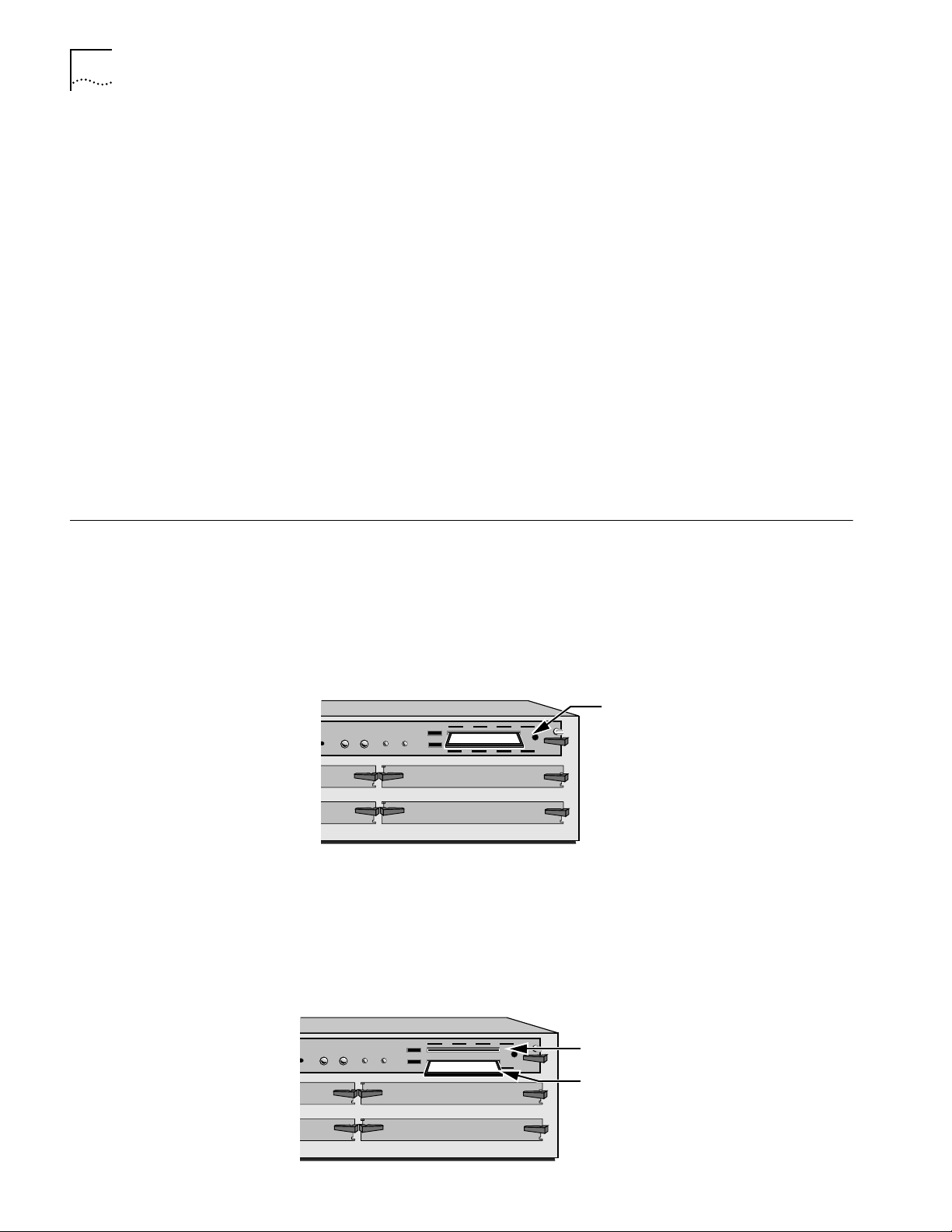
Insert NETBuilder software
STATUS
PACKET
POWER/
RESET ATTENTION
FORWARD
FAULT
432
A
B
flash memory card into drive A
NETBuilder II 4-Slot chassis
■ Log on to the system as root.
Procedure To make a backup copy of the NETBuilder software flash memory card, follow
these steps:
1 Insert a supported blank flash memory card into drive B of the DPE module.
Refer to the software release notes for a list of flash memory cards that can be
used with the DPE module.
PACKET
STATUS
POWER/
RESET ATTENTION
FORWARD
FAULT
432
A
B
Original flash memory card in drive A
Insert blank flash memory card in drive B
Page 15
Using the Backup Flash Card 2-3
PACKET
FORWARD
POWER/
FAULT
RESET ATTENTION
432
ATUS
A
B
Copy contents of drive A to the directory
you created on drive B
PACKET
FORWARD
POWER/
FAULT
RESET ATTENTION
432
A
B
Replace original card in drive A
with new copy from drive B.
Keep the original card as a backup.
2 Format the blank flash memory card in drive B by entering:
FORMAT b:
Type Y for yes when the formatting confirmation message is displayed.
3 Create a directory on the formatted flash memory card by entering:
MakeDir b:primary
4 Copy the software from the NETBuilder software flash memory card in drive A to
the formatted flash memory card in drive B by entering:
COpy a:/primary/* b:/primary/
5 After you have copied the softwar e, r eplace the original NETBuilder softwar e flash
memory card in drive A with the backup copy from drive B.
Keep the original NETBuilder software flash memory card in a safe place and
protect it from accidental damage. The original is your backup in the rare event
that the NETBuilder software or the backup flash memory card becomes
corrupted. Refer to ”Using the Backup Flash Card” on page 2-3 for instructions on
installing the backup flash memory card.
6 The NETBuilder software boot files for a DPE module are factory shipped with
a:/primary/boot.29k as the default primary boot source. If you have installed the
NETBuilder software on drive A, and you want to keep the same boot file as the
boot source, use the Reboot command to reboot your NETBuilder II bridge/router
by entering:
ReBoot
7 If you want to configure your primary boot source to a drive and file other than
the default, refer to Chapter 3 for instructions on configuring the boot source for
the NETBuilder II bridge/router.
Using the Backup Flash Card
If the NETBuilder software has been corrupted and you need to reboot, use your
original NETBuilder II software flash memory card to reset your system by
following these steps:
1 Remove the corrupted flash memory card from the DPE module.
2 Insert the original NETBuilder software flash memory card into drive A on the DPE
module.
Page 16

2-4 CHAPTER 2: INSTALLING SOFTWARE AND BOOTING A DPE NETBUILDER II SYSTEM
3 Reboot the NETBuilder II bridge/router by pressing the two outer buttons on the
LCD control panel.
The system boots from the NETBuilder II software flash memory card in drive A.
4 Make a copy of the flash memory card in drive A by following the steps in the
previous procedure.
You will need to either obtain an additional flash memory card or reformat the
corrupted flash memory card. If you choose to reformat a corrupted flash memory
card, inspect the card to make sure that it is not damaged. Always keep the
original NETBuilder II software flash memory card in a safe place and protect it
from accidental damage.
Page 17
CHANGING THE BOOT SOURCE ON A
3
Using the Boot Command
DPE NETB
This chapter describes how to change the primary boot source on a NETBuilder II
bridge/router with a DPE module.
The NETBuilder software boot files for a DPE module are factory shipped with
a:/101/boot.29k as the default primary boot source. If you have installed the
NETBuilder software flash memory card into drive A, and you want to keep the
default boot source, skip this chapter and refer to Chapter 6.
If you want to adjust system configuration settings, refer to the SysconF appendix in
Reference for NETBuilder Family Software for instructions on how to make the
changes.
The Boot Monitor utility Boot (BT) command allows you to reboot or to override the
default boot path. The BT command is useful if the boot path has a typing error or
if you have a malfunctioning drive. If you enter a new boot path, the Primary Boot
Source parameter is updated to reflect the new path.
UILDER II SYSTEM
Reset
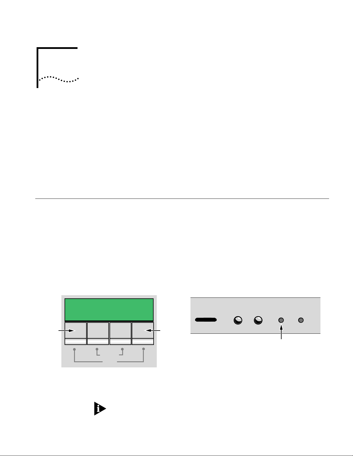
To reboot the NETBuilder II bridge/router using the Boot Monitor utility Boot
command, follow these steps:
1 Reset the system in one of two ways. Either press the two outer buttons on the
LCD control panel on the front of the NETBuilder chassis, or press the reset
button on the DPE module.
LCD control panel buttons on front panel
of a NETBuilder II bridge/router
Attention
Reset
Push both reset buttons simultaneously
The console displays the following startup message:
Do you want to enter the boot monitor? (y/n)
Entering Y within five seconds enters the boot monitor. If you enter N or enter
nothing, the NETBuilder II system begins booting the software.
Reset
STATUS
DPE module
PACKET
FORWARD
4321
POWER/
FAULT
Reset button on DPE module
RESET ATTENTION
For more information about the Boot Monitor utility, refer to the Firmware appendix
in Reference for NETBuilder Family Software.
Page 18

3-2 CHAPTER 3: CHANGING THE BOOT SOURCE ON A DPE NETBUILDER II SYSTEM
2 To enter the Boot Monitor utility, enter:
Y
3 Enter a boot path using:
BT <drive>: /<path>/<filename>
If you do not enter the <drive> value, drive A is used. To boot from drive A, enter:
BT a:/primary/boot29.k
The system attempts to boot from the specified image file. If an error occurs, a
message is sent to the console and you are returned to the boot monitor.
For more information about the Boot Monitor utility refer to the Boot Monitor
appendix in Reference for NETBuilder Family Software.
Configuring the
Primary Boot Source
Prerequisites Before beginning this procedure, complete the following tasks:
Procedure To change the primary boot source to a drive or file other than the default or the
Drive A is the default primary boot source. This procedure establishes drive B as
the primary boot source.
■ Install the system software and boot the NETBuilder II system according to the
instructions in Chapter 2.
■ Attach a terminal, a PC with a terminal emulation program, or a modem for
using a remote PC to the console port on the DPE module and make sure that
this terminal is operating properly. If your terminal is not operating properly,
refer to the hardware installation guide for setup instructions.
current drive setting, follow these steps:
1 Press the Return key.
The following prompt is displayed on your console:
NetLogin:
2 Log on as root by entering:
root
3 Press the Return key.
Pressing the Return key when prompted for the password enters a null string,
which is the default local password.
The bridge/router system prompt is displayed:
NETBuilder #
You are now ready to enter software commands.
4 At the NETBuilder prompt, enter:
SysconF 2
The Primary Boot Source menu is displayed:
Primary Boot Source:
1. Boot Filename: a:/primary/boot.29k
2. Config File Source a:/primary
3. IP Addresses Client:none Subnet Mask:none
4. FTP Login Parameters
Enter parameter number or press Q to quit:
Page 19

Configuring the Primary Boot Source 3-3
5 Enter 1 to select a boot filename.
Information similar to the following is displayed:
Current Boot Filename: a:/101/boot.29k
Enter Boot Filename (CR = no change):
6 Enter a new boot filename (such as b:/101/boot.29k) and press the Return key.
The configuration files must reside on the same drive as the boot source. If the
drive you specify is different from the configuration boot source drive, you are
prompted to change the configuration file source to the same drive.
If the boot drive you specify conflicts with the one set in the Dump Destination
parameter, you are prompted for a different drive.
7 Enter q to quit the menu.
The System Configuration menu showing the new entries is displayed:
System Configuration
1. Serial Ports Console: 9600
2. Primary Boot Source b:/101/boot.29k, b:/
3. Secondary Boot Source b:/boot.29k, b:/
4. Test Boot Source a:/boot.29k, a:/:
5. Boot Sources Primary and Secondary
6. Dump Destination Partial dump only
7. Recovery Procedure
8. MP Boot Source
9. Boot Statistics Booted: 1 Exceptions: 0
Enter parameter number or press Q to quit:
8 Enter q to quit the configuration program.
9 At the prompt, enter:
ReBoot
The NETBuilder II bridge/router reboots using the newly established drive B as the
primary boot source.
For drive B to function as the boot source, a flash memory card with software
version 10.1 must be installed in drive B.
Page 20

3-4 CHAPTER 3: CHANGING THE BOOT SOURCE ON A DPE NETBUILDER II SYSTEM
Page 21

INSTALLING SOFTWARE AND BOOTING
4
Installing Software and Performing Initial Boot
A CEC 20 NETBUILDER II SYSTEM
This chapter contains the following procedures:
■ Installing and booting NETBuilder software
■ Making a backup copy of the software flash memory card
NETBuilder software can be installed in the following ways:
■ From a flash memory card with preinstalled software. 3Com recommends this
method.
EZBuilt NETBuilder II systems have a factory-installed software flash memory
card. To boot your EZBuilt system, refer to “Booting an EZBuilt NETBuilder II
System.”
For component NETBuilder II systems to boot from a flash memory card, they
mus have a flash memory drive installed. For installation instructions, refer to
the NETBuilder II Flash Memory Drive Installation Guide. After you have
installed a flash memory drive, refer to “Booting a Component NETBuilder II
System” on page 4-2 for instructions on booting your system.
Booting from the Flash Memory Card
Prerequisites Before you boot your new NETBuilder II system, you need to complete all setup
Booting an EZBuilt
NETBuilder II System
■ From CD-ROM on a UNIX-based or PC-based network management station
using TFTP
To start your NETBuilder II system from a flash memory card with preinstalled
software, follow the procedures in this section.
and installation instructions in the hardware guide provided with the system and
system components. You also need to connect a console to your system.
The EZBuilt NETBuilder II system comes with a factory-installed flash memory card
that contains the NETBuilder software. To boot an EZBuilt NETBuilder II system,
follow these steps:
1 Turn on the EZBuilt NETBuilder system.
The NETBuilder II system boots from the default boot source a:/101/boot.29K (the
flash memory drive).
2 When the boot operation is complete, press the Return key on the console.
The NETBuilder console prompt should appear on the screen.
If the console is not operating properly (if you see incorrect characters, or no
characters), refer to the setup instructions in the hardware installation guide.
You are ready to establish basic settings on your system. Refer to Chapter 6 for
more information.
Page 22
4-2 CHAPTER 4: INSTALLING SOFTWARE AND BOOTING A CEC 20 NETBUILDER II SYSTEM
Booting a Component
NETBuilder II System
To boot a component NETBuilder II system, follow these steps:
1 Install a flash memory drive in your NETBuilder II system. For instructions, refer to
the NETBuilder II Flash Memory Drive Installation Guide.
2 Install a flash memory card with preinstalled software in the flash memory drive.
To install the flash memor y card, turn off the bridge/router, disconnect the
cables, and remove the cover. Insert the flash memor y card into the flash
memory drive. Reinstall the cover and reconnect the power cord and other
cables.
3 Turn on the NETBuilder II bridge/router.
The NETBuilder II system boots from the default boot source a:/101/boot.29K (the
flash memory drive).
4 When the boot operation is complete, press the Return key on the console.
The NETBuilder console prompt should appear on the screen.
If the console is not operating properly (if you see incorrect characters, or no
characters), refer to the setup instructions in the hardware installation guide.
You are ready to establish basic settings on your system. Refer to Chapter 6 for
more information.
If you want to change the primary boot source from the default or adjust system
configuration parameters, refer to Chapter 5 and the description in the SysconF
appendix in Reference for NETBuilder Family Software.
Installing Software
from a Network
Management Station
Setting Up the
UNIX-based Network
Management Station
This section describes how to install the NETBuilder II bridge/router software from
CD-ROM on a UNIX-based or PC-based network management station with a
CD-ROM drive.
The procedures in this section apply to the NETBuilder II component system only.
This section contains the following procedures:
■ Installing software on the UNIX-based network management station
■ Installing sofware on the PC-based network management station
■ Booting a NETBuilder II image over the network
■ Setting up IP routing on the NETBuilder II bridge/router
■ Copying image files to the local NETBuilder II bridge/router flash drive for local
booting and rebooting
This procedure provides instructions for setting up the UNIX-based network
management station (see Figure 4-1).
Prerequisites
To install the NETBuilder bridge/router software image from a CD-ROM, the
CD-ROM drive must reside either locally on the network management station or
on another system on the network.
Page 23

Installing Software from a Network Management Station 4-3
Before installing the software from CD-ROM, make sure that:
■ Your network management station is running Solaris 2.4 or 2.5x, SunOS 4.1.4,
HP-UX 9.0.5, 10.10 or 10.20, or IBM AIX 3.2.5, 4.1.4 or 4.2. To verify the
operating system environment, enter:
uname -a
The version message refers to Solaris 2.5x as SunOS 5.5.
■ You know the root password.
■ The network management station has sufficient disk space for the amount of
software you are installing. Minimal disk storage requirements are dependent
on the number of NETBuilder systems being installed. Allocate 40 MB for the
NETBuilder Upgrade Management Utilities and software image, 4 MB for each
NETBuilder II system.
■ The NETBuilder Upgrade Management Utilities released with this software
package have been installed on the network management station. Refer to
Upgrading NETBuilder Family Software for more information.
■ Install a blank flash memory card in the NETBuilder II bridge/router. For
installation instructions, refer to the NETBuilder II Flash Memory Drive
Installation Guide.
For a list of flash memory cards that can be used with the CEC 20 module, refer
to the software release notes.
At the network management station:
Insert NETBuilder II software CD-ROM into
a
CD-ROM drive on NMS
Copy the NETBuilder II software to TFTP boot
b
directory on NMS
c
Select TFTP file in the NMS as primary boot source
UNIX-based NMS
Running
recommended
CD-ROM
TFTP
TCP network
Figure 4-1 Installing NETBuilder II Software from CD-ROM on a UNIX NMS
At the console:
Set up IP routing
d
Transfer software to NETBuilder II with TFTP
e
Console
CEC 20 module
CEC
®
CPU ACT PKT FWD
SELF TEST
4321
BOOT POWER
FDDI MAC
®
A STATUS
1
A
FDDI PHY
®
SINGLE-MODE
2
SINGLE
3
4
CONSOLE AUXILIARY DIAGNOSTIC
STATUS
BYPASS
B STATUS
STATUS
B
COMPLIES WITH 21 CFR
1040.10 & 1040.11
3COM CORP. BLDG. 300
SANTA CLARA, CA
NOVEMBER 1993
SINGLE
8
7
6
5
NETBuilder II bridge/router
Procedure
To install the NETBuilder software on the UNIX network management station,
follow these steps:
1 Format the blank flash memory card in drive A by entering:
FORMAT A:
Type Y for yes when the formatting confirmation message is displayed.
Page 24

4-4 CHAPTER 4: INSTALLING SOFTWARE AND BOOTING A CEC 20 NETBUILDER II SYSTEM
2 Make sure the TFTP server on the network management station is running and has
been correctly configured by confirming that the TFTP or inetd daemons are running.
To see if these daemons are running, enter:
ps ax |more
The resulting display shows every active process on the system.
3 Mount the software CD-ROM on the network management station.
For mount instructions for your specific UNIX operating system, refer to Upgrading
NETBuilder Family Software.
4 Set environmental variables with the location of NETBuilder Upgrade Management
Utilities.
These variables depend on the UNIX shell that is installed at your site.
■ If you are using a C-shell (csh), enter:
source /usr/3Com/common/data/.login-bcm
■ If you are using a Bourne (sh) or Korn (ksh) shell, enter:
. /usr/3Com/common/data/.profile-bcm
5 Ensure that you are using the version of the NETBuilder Upgrade Management
Utilities that shipped with your software.
To check the version you have installed, enter:
bcmdiagnose -h
The version of the installed utilities is displayed in the following message:
bcmdiagnose version 10.1. Copyright 3Com Corporation 1997
If the version of the utilities you installed differs from the version shipped with your
software package, you must first install the utilities shipped with your software
package.
In the next step, the bcminstall utility extracts the files from the CD-ROM and
installs them on the network management station hard disk in the
/tftpboot/image/<platform>/ SW|FW/<version> /<pkg> directory. For example, the
software may be installed in the /tftpboot/image/NBII/SW/101/FF directory. If the
disk has insufficient space, you can link /tftpboot to another disk.
6 If necessary, mount the CD-ROM drive on your UNIX system. Refer to your system
documentation for instructions.
7 Using the NETBuilder Upgrade Management Utilities, install the NETBuilder
bridge/router software from the CD-ROM by entering:
bcminstall
The optional path parameter can also be used to install the software on a network
management station with two or more drives connected, as well as to install from
a remote CD-ROM drive. You must explicitly specify the second CD-ROM drive.
To install a NETBuilder package from a second CD-ROM drive on a Solaris machine,
enter:
bcminstall -cdrom /cdrom/cdrom1/image
After the installation is complete, the screen shows an inventory of all NETBuilder
packages installed, including previous versions you have installed. You are now ready
to go to “Booting a NETBuilder II Image over the Network” on page 4-6.
Page 25

Installing Software from a Network Management Station 4-5
Setting Up the PC-based
Network Management
Station
At the network management station:
This section describes how to install NETBuilder II software from a CD-ROM on a
PC network management station (see Figure 4-2).
Prerequisites
Before you install software and boot your new NETBuilder II system, you need to
complete the procedures that apply to your system in the hardware installation
guide. These procedures include installing components, setting up the system,
attaching network and power cables, and attaching a terminal, PC (with a
terminal emulation application), or modem to the console port on the DPE
module.
Determine which TFTP server product you will use for the installation. You can
successfully use the following products to install software from a PC-based
network management station:
■ A PC network management station with TFTP server capability
■ Transcend Enterprise Manager for Windows 5.0 or later
■ NETManage Chameleon version 4.0 or later
■ FTP Software PC/TCP tools
■ Distinct Corporation TCP/IP tools
■ Novell LAN WorkPlace 5.0 or later
Insert CD-ROM with NETBuilder II
a
software into NMS drive
Copy the NETBuilder II software to
b
TFTP boot directory on NMS
c
Select TFTP file in the NMS as
primary boot source
Running
recommended
TFTP
TCP network
At the console:
Set up IP routing
d
e
With TFTP, transfer software to NETBuilder II
Console
PC NMS
CD-ROM
CEC
®
SELF TEST
FDDI MAC
®
A STATUS
1
FDDI PHY
®
SINGLE-MODE
2
3
4
CEC 20 module
CPU ACT PKT FWD
STATUS
4321
BOOT POWER
BYPASS
B STATUS
STATUS
A
B
COMPLIES WITH 21 CFR
1040.10 & 1040.11
3COM CORP. BLDG. 300
SANTA CLARA, CA
NOVEMBER 1993
SINGLE
SINGLE
CONSOLE AUXILIARY DIAGNOSTIC
NETBuilder II bridge/router
Figure 4-2 Installing NETBuilder II Software from CD-ROM on a PC NMS
Procedure
To install the bridge/router software, follow these steps:
1 Insert the software CD-ROM into the PC CD-ROM drive.
8
7
6
5
2 Ensur e that the TFTP server is active and that it r efer ences the r oot dir ectory of the
CD-ROM.
Refer to the TFTP server documentation for information regarding procedur es that
you need to use to adjust the server parameters.
You are now ready to boot the NETBuilder II image over the network.
Page 26

4-6 CHAPTER 4: INSTALLING SOFTWARE AND BOOTING A CEC 20 NETBUILDER II SYSTEM
Booting a NETBuilder II Image over the Network
This section describes how to boot the NETBuilder II image over the network,
which can be done from either a UNIX-based or PC-based network management
station.
Network booting is supported over Ethernet, token ring, FDDI (but not FDDILink),
and HSS ports using PPP.
Table 4-1 lists additional boot source parameter settings, such as those related to
booting over a token ring port, an HSS port using PPP, or a multiport Ethernet
module. You may need to adjust these parameters based on your particular
configuration.
Table 4-1 TFTP Primary Boot Source Parameter
Parameter Configuration
Boot Device:
Network
Interface number.
You are prompted with this field only if an Ethernet 2-Port or Ethernet 6-Port module resides in the slot. Make
sure this parameter is set to the appropriate interface (A or B or A–F). The default is A.
MP Module
Parameters
You need to configure this parameter only if the TFTP server is reachable through an HSS port running PPP or a
token ring port.
HSS port running PPP
If the boot source is reachable through an HSS port running PPP, you are prompted to configure the
following fields:
■ HSS Baud Rate
This setting must correspond to the serial line setting.
■ HSS Clock Source
Set this parameter appropriately (the default setting is external).
■ HSS Connector Type
Set this parameter to the connector that the server is reachable through (the default is V.35).
■ HSS Protocol
Select PPP.
■ HSS WAN Password
Leave this field empty.
Token ring port
If the boot source is reachable through a token ring port, you are prompted to configure the following fields:
■ Token Ring Speed
This setting must correspond to the token ring line setting (the default is 4 Mbps).
■ Token Ring Baud Rate
Make sure the setting of this field corresponds to that of the token ring line.
Boot Protocol Make sure the Boot Protocol is set to TFTP.
If you are configuring the bridge/router to use TFTP only, set the Address Discovery Protocol to Local Configured
Addresses.
If you are configuring the bridge/router to use TFTP and BOOTP, set the Address Discovery Protocol to BOOTP.
Boot Sources Make sure the Boot Sources are set to Primary and Secondary.
MAC Address Make sure this parameter is set to the CEC MAC address.
ARP Format If the boot source is reachable through a token ring port, make sure that the setting of this parameter agrees
with the Address Resolution Protocol (ARP) format used on the token ring network: noncanonical.
.
Page 27

Booting a NETBuilder II Image over the Network 4-7
Procedure
To boot the NETBuilder II image over the network, follow these steps:
1 Turn on the NETBuilder II system or press the two outer buttons on the LCD panel on
the front of the chassis to reset the system.
2 Enter Y when the system asks if you want to enter the monitor.
3 From the NETBuilder monitor prompt (>), enter:
SF
The System Configuration menu is displayed.
4 Ensure that the System Configuration entry number 3, Start-Up Action, is set to Try
boot once.
If Start-Up Action is not set to Try boot once, follow these steps:
a From the System Configuration menu, enter 3.
The Start-Up Action menu is displayed.
b Enter 3 to select Try boot once and press the Return key.
The System Configuration menu showing the Start-Up Action as Try boot once
is displayed.
TFTP is a UDP-based function.Frames may be lost in transit. If this occurs, and the
Start-Up Action is not set to Tr y boot once, lost frames can cause the boot process
to continuously retry without success. Set the Start-Up Action to Try boot once to
avoid this situation.
5 From the System Configuration menu, enter 4 to select Primary Boot Source.
The Primary Boot Source menu is displayed.
6 Enter 1 to select the Boot Device option, and enter 2 to set the Boot Device to
Network.
You are then prompted to set the slot number and boot filename.
7 Enter the slot number of the module that is used to reach the TFTP server.
If you have a 4-Slot chassis, your options are 1 through 4. If you have an 8-Slot
chassis, your options are 1 through 8.
8 Enter the image filename by entering the directory path and the filename relative to
the tftpboot directory where the CEC boot image resides.
For example:
/image/NBII/SW/101/FF/boot.29k
You do not need to specify the /tftpboot director y because the TFTP server
assumes the /tftpboot directory by default.
9 Enter Q to return to the Primary Boot Source menu.
10 Enter 5 to select the Boot Protocol option, and set the Primary Boot Protocol to TFTP.
You are then prompted to set the TFTP Address Discovery Protocol.
11 Set the TFTP Address Discovery Protocol to Local Configured Addresses.
12 Enter Q to return to the Primary Boot Source menu.
13 Enter 6 to select IP Addresses, and enter the primary IP addresses assigned to the
TFTP client, TFTP server, gateway, remote file server, and subnet mask.
Page 28

4-8 CHAPTER 4: INSTALLING SOFTWARE AND BOOTING A CEC 20 NETBUILDER II SYSTEM
14 Enter Q repeatedly to return to the System Configuration menu.
15 Ensure that Boot Sources is set to Primary and Secondary.
If Boot Sources is not set correctly, follow these steps:
a From the System Configuration menu, enter 7.
b From the Boot Sources menu, enter 2.
16 Exit the menu system by typing Q repeatedly.
17 To boot the software image from the network management station, enter:
NB
The bridge/router obtains its software image from the network management
station and boots.
When the following message is displayed:
System Initialized and Running
the bridge/router has finished booting.
Copying the Software to a Flash Memory Card
Configuring IP Before you copy the software to the NETBuilder II bridge/router flash memory
To boot locally, the software image boot file must be copied to the flash memory
card in drive A.
card, you must configure IP for the port that the NETBuilder II bridge/router can be
accessed through.
This procedure assumes that you have just booted the NETBuilder bridge/router
over the network.
To configure IP on the NETBuilder II bridge/router, follow these steps:
1 Press the Return key.
The following prompt is displayed on the console:
NetLogin:
2 Log on as root:
root
3 Press the Return key.
Pressing the Return key when prompted for the password enters a null string,
which is the default local password.
The bridge/router system prompt is displayed:
NETBuilder #
You are now ready to begin using the software and entering software commands.
4 Set up an IP address and subnet mask using:
SETDefault !<port> -IP NETaddr = <IP address> [<subnet mask>]
For more information on IP configuration, refer to Reference for NETBuilder Family
Software.
5 Enable IP routing by entering:
SETDefault -IP CONTrol = RO
Page 29

Copying the Software to a Flash Memory Card 4-9
6 Enter a routing protocol.
For example, enable RIP using:
SETDefault !<port> -RIPIP CONTrol = (Listen, Talk)
7 Confirm your configuration by verifying that the NETBuilder II bridge/router can
reach the network management station using:
PING <IP address>
where <IP address> is the IP address of the network management station.
Copying Software to the
NETBuilder II Using TFTP
To copy the software from the network management station to the NETBuilder II
bridge/router using TFTP, follow these steps:
1 If you have not already done so, insert a blank flash memory card in drive A.
Refer to the software release notes for a list of flash memory cards that can be used
with the CEC 20 module.
For instructions on installing the flash memory drive and inserting a flash memory
card, refer to the NETBuilder II Flash Memory Drive Installation Guide.
2 Format the blank flash memory card by entering:
FORMAT a:
Type Y at the formatting confirmation message.
3 Create a destination directory on the flash memory card.
MakeDir a:/primary
4 Copy the NETBuilder II software images from the network management default
directory (tftpboot) into the /primary directory on the flash memory card.
For example:
COpy 192.65.74.10:image/NBII/SW/primary/FF/boot.29k a:/primary/boot.29k
where 192.65.74.10 is the IP address of the network management station.
The software images to copy to the NETBuilder II bridge/router may include the
following files:
■ boot.29k – Image file that boots the CEC20 module
■ ccsmacro – File that contains predefined user macros
■ sys – File that is used during the upgrade process to determine the source and
target software versions
■ mp6e.29k – Image file that boots the multiprocessor Ethernet module
■ mpatm.29k – Image file that boots the multiprocessor ATM module
To change your bridge/router primary boot source, refer to Chapter 5.
Page 30

4-10 CHAPTER 4: INSTALLING SOFTWARE AND BOOTING A CEC 20 NETBUILDER II SYSTEM
Page 31

CHANGING THE BOOT SOURCE ON A
5
Configuring the
Primary Boot Source
Prerequisites Before beginning this procedure, complete the following tasks:
CEC 20 SYSTEM
This chapter describes how to change the primary boot source on a NETBuilder II
bridge/router with a CEC 20 module.
The NETBuilder software boot files for a CEC 20 module are factory shipped with
a:/101/boot.29k as the default primary boot source. If you have installed the
NETBuilder software flash memory card into drive A, and you want to keep the
default boot source, skip this chapter and refer to Chapter 6.
If you want to adjust system configuration settings, refer to the SysconF appendix in
Reference for NETBuilder Family Software for instreuctions on how to make the
changes.
Drive A is the default primary boot source. This procedure establishes Network and
slot 7 as the primary boot source.
■ Install the system software and boot the NETBuilder II system according to the
instructions in Chapter 4.
■ Attach a terminal, a PC with a terminal emulation program, or a modem to the
console port on the CEC 20 module and make sure that the terminal is
operating properly. If your terminal is not operating properly, refer to the
hardware installation guide for setup instructions..
Procedure To change the primary boot source to a drive or file other than the default or the
current drive setting, follow these steps:
1 Press the Return key.
The following prompt is displayed on your console:
NetLogin:
2 Log on as root by entering:
root
3 Press the Return key.
Pressing the Return key when prompted for the password enters a null string,
which is the default local password.
The bridge/router system prompt is displayed:
NETBuilder #
You are now ready to enter software commands.
Page 32

5-2 CHAPTER 5: CHANGING THE BOOT SOURCE ON A CEC 20 SYSTEM
If the bridge/router is unable to boot, enter Y at the monitor prompt, as shown in
this screen display.
3Com Corporation NETBuilder II power-on
FW/NBII-FW,2.6
CEC*: 8 Mbytes IMEM, 8 Mbytes DMEM, 4 Mbytes SMEM
Booting from drive A ...
File - BOOT.29K - not found
Do you want to enter the monitor? (y/n) : y
3Com Corporation NETBuilder II Monitor
>
4 Access the System Configuration menu by typing SF at the NETBuilder command
prompt or in the firmware monitor.
Information similar to the following is displayed:
System Configuration
1. Serial Ports Console: 9600 Auxiliary: 9600
2. Self-Test Skip
3. Start-Up Action Try boot once
4. Primary Boot Source Drive A:
5. Secondary Boot Source Local: Drive A:
6. Test Boot Source Unknown boot source Slot: 0
7. Boot Sources Primary and Secondary
8. Dump Destination Do not dump
9. Recovery Procedure
10. MP Boot Source
11. Boot Statistics Booted: 7 Exceptions: 3
Enter parameter number or press Q to quit:
5 Enter 3 to select Start-Up Action.
Information similar to the following is displayed:
Start-Up Action: Try boot once
1. Enter monitor
2. Local
3. Try boot once
4. Try boot forever
Choose Start-Up Action or press Q to quit (CR=Try boot once):
6 Enter 4 to select Try boot forever.
Information similar to the following is displayed:
Start-Up Action: Try boot forever
1. Enter monitor
2. Local
3. Try boot once
4. Try boot forever
Choose Start-Up Action or press Q to quit (CR=Try boot forever):
7 Press the Return key to confirm.
Information similar to the following is displayed:
Updating EEPROM. Please wait . . .
System Configuration
1. Serial Ports Console: 9600 Auxiliary: 9600
2. Self-Test Skip
3. Start-Up Action Try boot forever
4. Primary Boot Source Drive A
5. Secondary Boot Source Local: Drive A:
6. Test Boot Source Unknown boot source Slot: 0
7. Boot Sources Primary and Secondary
Page 33

Configuring the Primary Boot Source 5-3
8. Dump Destination Do not dump
9. Recovery Procedure
10. MP Boot Source
11. Boot Statistics Booted: 7 Exceptions: 3
Enter parameter number or press Q to quit:
Enter 4 to select Primary Boot Source.
Information similar to the following is displayed:
Primary Boot Source:
1. Boot Device: Drive A:
2. Default file source Local:
3. Maximum retries 0
4. I/O Module Parameters Ethernet
5. Boot Protocol TFTP Local configured addresses
6. IP Addresses client:none
Subnet Mask:none
7. MAC Address System 08-00-02-05-1A-BE
8. ARP Format Canonical
9. FTP Login Parameters
Enter parameter number or press Q to quit:
8 Enter 1 to select Boot Device.
Information similar to the following is displayed:
Primary Boot Device:
Local: Drive A:
1. Local
2. Network
Choose Primary Boot Device or press Q to quit:
9 Enter 2 to select Network.
Information similar to the following is displayed:
Network Boot:
Choose a slot :
10 Enter the slot number where the CEC 20 is installed.
For example, type 7 to specify slot 7.
Information similar to the following is displayed:
Boot Filename: boot.29k
Enter Boot Filename (CR=no change):
11 Select the NETBuilder bridge/router software version 10.1 as the default boot
source file by entering:
/primary/boot.29k
Information similar to the following is displayed:
Primary Boot Device:
Network: Slot 7: /primary/boot.29k
1. Local
2. Network
Choose Primary Boot Device or press Q to quit:
Page 34

5-4 CHAPTER 5: CHANGING THE BOOT SOURCE ON A CEC 20 SYSTEM
12 Enter Q to quit the menu.
Information similar to the following is displayed:
Primary Boot Source:
1. Boot Device Network: Slot: 7 /primary/boot.29k
2. Default File Source Boot Device:
3. Maximum Retries 0
4. I/O Module Parameters Ethernet
5. Boot Protocol TFTP Local configured addresses
6. IP Addresses client:none
7. MAC Address System 08-00-02-05-1A-BE
8. ARP Format Canonical
9. FTP Login parameters
Enter parameter number or press Q to quit:
13 Enter 2 to select Default File Source.
Information similar to the following is displayed:
Current Default File Source: Boot Device
1. Boot Device
2. Local
3. Network
Choose a Primary Default File Source or press Q to quit:
Subnet Mask:none
14 Enter 2 to select Local.
Information similar to the following is displayed:
Current Default Directory for Files:
Enter Default Directory for Files (CR=no change):
15 To select NETBuilder software version 10.1 enter:
/primary
Information similar to the following is displayed:
Current Default File Source: Local: /primary
1. Boot Device
2. Local
3. Network
Choose a Primary Default File Source or press Q to quit:
16 Enter Q to quit the menu.
Information similar to the following is displayed:
Primary Boot Source:
1. Boot Device Network: Slot: 7 /primary/boot.2k
2. Default File Source Local: /primary
3. Maximum Retries 0
4. I/O Module Parameters not used
5. Boot Protocol TFTP Local configured addresses
6. IP Addresses client:none
Subnet Mask:none
7. MAC Address System 08-00-02-05-1A-BE
8. ARP Format Canonical
9. FTP Login parameters
Enter parameter number or press Q to quit:
Page 35

Configuring the Primary Boot Source 5-5
17 Enter Q to quit the menu.
Information similar to the following is displayed:
System Configuration
1. Serial Ports Console: 9600 Auxiliary: 9600
2. Self-Test Skip
3. Start-Up Action Try boot forever
4. Primary Boot Source Network: Slot: 7 /primary/boot.29k
5. Secondary Boot Source Local: /primary
6. Test Boot Source Unknown boot source Slot: 0
7. Boot Sources Primary
8. Dump Destination Do not dump
9. Recovery Procedure
10. MP Boot Source
11. Boot Statistics Booted: 7 Exceptions: 3
Enter parameter number or press Q to quit:
18 Ensure that Boot Sources are set to Primary. If the Boot Sources are set correctly,
proceed to step 22. If the Boot Sources are not set to Primary and Secondary,
proceed to the next step.
19 Enter 7 to select Boot Sources.
Information similar to the following is displayed:
Boot Sources: Primary and Secondary
1. Primary
2. Primary and Secondary
3. Secondary
Choose Boot Sources or press Q to quit(CR=Primary and Secondary):
20 Enter 2 to select Primary and Secondary.
Information similar to the following is displayed:
Boot Sources: Primary and Secondary
1. Primary
2. Primary and Secondary
3. Secondary
Choose Boot Sources or press Q to quit (CR=Primary):
21 Press the Return key to confirm Primary.
Information similar to the following is displayed:
System Configuration
1. Serial Ports Console: 9600 Auxiliary: 9600
2. Self-Test Skip
3. Start-Up Action Try boot forever
4. Primary Boot Source Network: Slot: 7 /primary/boot.29k
5. Secondary Boot Source
6. Test Boot Source Unknown boot source Slot: 0
7. Boot Sources Primary and Secondary
8. Dump Destination Do not dump
9. Recovery Procedure
10. MP Boot Source
11. Boot Statistics Booted: 9 Exceptions: 6
Enter parameter number or press Q to quit:
Local: /primary
22 Enter Q to quit the firmware configuration program.
23 At the monitor prompt, enter bt to reboot the NETBuilder II bridge/router from
firmware, or enter rb to reboot the bridge/router from software.
Page 36

Page 37

6
CONFIGURING BASIC SETTINGS
This chapter describes preliminary tasks for configuring basic bridge/router
settings. Before you begin configuring ports and paths (described in Chapter 1 of
Using NETBuilder Family Software), complete the following tasks:
■ Log on to the system.
■ Familiarize yourself with the user interface.
■ Learn how to get help.
■ Set up IP routing.
■ Store configuration parameter values.
■ Obtain Network Manager privileges.
■ Change the Network Manager password.
■ Set the time and date.
■ Set system administrator information.
■ Assign IP addresses and subnet masks to individual ports or one address for the
bridge/router.
■ Set up the Simple Network Management Protocol (SNMP).
■ Set up NETBuilder security.
Logging on to the System
To log on to the bridge/router, follow these steps:
1 Turn the bridge/router on or press the two outer (reset) buttons on the LCD panel
on the front of the chassis.
The bridge/router takes a few minutes to complete the initialization process.
Startup messages appear on your console display.
When you see the following message:
System Initialized and Running
the bridge/router has finished booting.
2 Press the Return key.
The following prompt is displayed on your console:
NetLogin:
3 Log on as root:
root
4 Press the Return key.
Pressing the Return key when prompted for the password enters a null string,
which is the default local password. Later in this chapter, you will be instructed on
how to change the password.
Page 38

6-2 CHAPTER 6: CONFIGURING BASIC SETTINGS
The bridge/router system prompt is displayed:
NETBuilder #
You are now ready to begin entering software commands.
Learning About the User Interface
Accessing the User
Interface
This section describes how to access the bridge/router user interface and provides
an overview of the menu-driven and command-line interfaces.
This section also includes the following information:
■ How to specify values, set members, or set addresses when using either the
menu-driven or command-line interface
■ How to use online help
To access the user interface or to modify the configuration of the NETBuilder
bridge/router, use one of the following methods:
■ Access the bridge/router commands locally through the console port.
■ Establish a Telnet session with the bridge/router using security passwords.
■ Use a device (for example, a workstation) on the same extended network or
internetwork to access the bridge/router through the Telnet protocol.
NETBuilder software also supports outgoing Telnet.
The software supports TCP and UDP over Bigger Addresses (TUBA), which
means you can Telnet to the bridge/router using an IP address or an OSI
NSAP address from a PC or workstation. For more information about using
Telnet on a workstation, refer to the manual that accompanies the
workstation.
■ View and configure a subset of bridge/router parameters from a remote host
using SNMP. For information on preparing the bridge/router to run SNMP, refer
to Using NETBuilder Family Software.
Menu-Driven Versus
Command-Line Interface
Using the Menu-Driven
Interface
After accessing the user interface, you need to decide whether to use the
menu-driven interface or the command-line interface.
After accessing the bridge/router user interface, you can issue a command in one
of two ways:
■ Use the menu-driven interface if you are unsure of the command syntax.
For more information about the MEnu command, refer to Reference for
NETBuilder Family Software. For information on how to use the menu-driven
interface, see the next section.
■ Enter the command at the system prompt if you know the exact syntax.
For information about the command line and rules for entering commands,
refer to “Using the Command-Line Interface” on page 6-3.
The syntax for each command and parameter is described in Reference for
NETBuilder Family Software.
The MEnu command allows you to perform the following operations:
■ List the services available on the bridge/router.
■ Choose a service and see the list of parameters available for the service.
■ List the parameters in the current service.
Page 39

Learning About the User Interface 6-3
■ Choose a parameter and see the commands used with it.
■ Check the active and default values of a particular parameter.
■ Display the syntax of a particular parameter.
■ Enter the new value of a parameter.
To use the menu-driven interface, you must have Network Manager privilege.
When using the menu-driven interface, you cannot access some parameters; for
example, you cannot alter the number of lines on the screen, or change privilege
level. Accessing the NETBuilder bridge/router through the REMote command
requires the command-line interface.
To use the menu-driven interface, follow these steps:
1 Access the main menu by entering:
MEnu
The Main menu (Level 1) is displayed.
Depending on your software package, the number of services in your Main menu
may vary.
2 Select the desired service.
Using the
Command-Line Interface
For example, selecting 1 from the Main menu (Level 1) display generates a menu
for the SYS Service.
3 Select the parameter you want to configure.
For example, if you select the NMPrompt parameter from the SYS Service menu
(Level 2) menu, information for that parameter is displayed.
The first part of the screen displays the value of the parameter; the second part
lists the commands you can choose. For information on help menus, refer to
“Getting Help” on page 6-16. For complete rules for entering commands and
using aliases and history substitution, refer to “Using Aliases” on page 6-8,
“Command History Substitution” on page 6-8, and “Command-Line Parameter
Attributes” on page 6-9.
4 To return to the previous menu level, press the Return key.
If you are at the Main menu (level 1) and press the Return key, you return to the
command-line interface.
This section describes how to enter commands and provides detailed information
about using the command-line interface.
To use the command-line interface, follow these steps:
1 Type the command name.
If the command does not include a service name, parameter, or values, skip to
step 3. If the command requires more information or if you want to include
optional arguments, continue to step 2a.
If you need help identifying the parts of a command, see Figure 6-1.
a If the command has additional options, such as a port or path number,
include them after the command name.
Including a specific port or path number in the command focuses the
command on that port or path. If the port or path number is not included,
the command acts on all ports or paths.
Page 40

6-4 CHAPTER 6: CONFIGURING BASIC SETTINGS
For more information on ports and paths, refer to Chapter 1 in Using
NETBuilder Family Software. For more information on commands, refer to
Chapter 1 in Reference for NETBuilder Family Software.
b If the command includes a parameter, type the service name (if necessary), the
parameter name, and values.
The service name focuses the action of the command on a particular
bridge/router service.
In some cases, you may not need to enter the service name. For example, if a
parameter is unique to a service, the service does not need to be specified. If
two or more services have parameters of the same name, you must include
the service name in the syntax. For more information, refer to “Entering
Service Names in Command Lines” on page 6-7.
The value part of the command specifies how you want the parameter to be
set. Values include numerics, strings, or addresses, depending on the
parameter. For additional information, refer to “Syntax for Assigning Values”
on page 6-10.
2 After entering the complete command, press the Return key.
The bridge/router software includes online help for commands, services,
parameters, and syntax, described in “Getting Help” on page 6-10. The syntax that
appears in online help is the full-form syntax; it contains full names and visual cues
for entering commands. Y ou can also enter commands using an abbreviated version
of the syntax.
For information on full-form and abbreviated syntax, read the following sections
and see Figure 6-1 and Figure 6-2. For additional information on short cuts for
entering commands, refer to “Using Aliases” on page 6-8 and “Command History
Substitution” on page 6-8.
Full-Form Syntax
To display the full-form syntax (provided by online help in NETBuilder software) type
a question mark (?) or a question mark with other options, as described in “Getting
Help” on page 6-16.
Figure 6-1 shows the parts and symbols that make up command syntax. For more
information on symbols, refer to “Symbols” on page 6-5.
Angle brackets enclose
variable parameters or
values. Do not enter brackets.
Command name
A hyphen always precedes service name and must
be entered if the service name is entered.
A vertical bar separates mutually exclusive
values in a list, one of which can be entered.
Service name
Do not enter the bar itself.
SETDefault !<path> -FDDI InsertPolicy = [Insert | DoNotInsert]
An exclamation point
must precede a port,
virtual port, or path number.
Figure 6-1
Full-Form Syntax
Parameter name
Square brackets enclose optional
values or a list of optional arguments.
Do not enter the square brackets.
Page 41
Learning About the User Interface 6-5
NETBuilder family bridge/router guides and online help use upper- and lowercase
letters to distinguish the full form of commands and command syntax from the
abbreviated form. You can enter a command in abbreviated form by typing only
the uppercase portion. It does not matter whether you type the command in
upper- or lowercase letters.
Abbreviated Syntax
Abbreviated syntax is the shortest unambiguous abbreviation of a command,
parameter, or value that can be entered. You can enter the abbreviated form in
lower- or uppercase letters at the NETBuilder prompt.
Figure 6-2 shows the abbreviated syntax that corresponds to the full-form syntax
in Figure 6-1.
Commands, parameters, and service names can be entered in abbreviated form.
Uppercase denotes the shortest unambiguous abbreviation of a command,
service name, or parameter.
Command name
Parameter name
Value
SETD !1 -FDDI IP = DNI
Figure 6-2
Additional syntax examples are provided in “Full and Abbreviated Syntax
Examples” on page 6-6.
Symbols
You may see a variety of symbols shown as part of the command syntax. These
symbols usually explain how to enter the command, and you do not type them as
part of the command itself. The exceptions to this rule are parentheses, the
hyphen, and the exclamation point, which you do type as part of the command.
Table 6-1 summarizes command syntax symbols.
Table 6-1
Symbol Description
angle brackets < > Enclose a variable or value. You must specify the variable or value; for
square brackets[ ] Enclose an optional value or a list of optional arguments. One or more
parentheses ( ) Enclose a list of values that can be assigned to a single parameter. At least
(continued)
Abbreviated Syntax
Command Syntax Symbols
example, in the syntax:
DELete -IP ADDRess <IP address>
you must supply an address for <IP address> when you enter the
command. Do not type the angle brackets.
values or arguments can be specified. For example, in the syntax:
SET PRIvilege = [User | NetMgr]
you can specify either User or NetMgr when you enter the command. Do
not type the square brackets.
one of them must be selected. You must type the parentheses and
separate the values with a comma if you are assigning more than one
value. For example, in the syntax:
SET CurrentPorts = ALL | (<port>, <port>)
you can specify two port numbers by enclosing them in parentheses and
separating them with a comma when you enter the command.
Page 42

6-6 CHAPTER 6: CONFIGURING BASIC SETTINGS
Table 6-1 Command Syntax Symbols (continued)
Symbol Description
vertical bar | Separates mutually exclusive items in a list, one of which must be entered.
ellipsis ... Following a parameter name or value, indicates that one or more
hyphen - A letter preceded by a hyphen represents a command option. Also, when
braces { } Enclose a list of values, one of which must be entered. For example, in
exclamation point ! A number preceded by an exclamation point represents a port, virtual
For example, in the syntax:
SET ScreenLength = [None | <line>(6–100)]
you can specify either the word None or a number between 6 and 100
when you enter the command. Do not type the vertical bar.
additional arguments may be specified on the same command line. For
example, in the syntax:
ADD !<port> -IP SecAuthIn <authority> [<authority>
...] [ANY]
you can specify multiple authorities (GENSER, SIOP, SCI, NSA, DOE, NONE)
when you enter the command. Do not type the ellipsis.
you enter a service name as part of the command, you must precede the
service name with a hyphen. For example, in the command:
SETDefault -BRidge CONTrol = Bridge
You must include the hyphen with the service name BRidge when you
enter the command.
the syntax:
SETDefault !<subaddr #> -Gateway SubAddrMap =
{(<IPaddr> | <PSAPaddr>) | None}
you must enter either an IP address, PSAP address, or the word None
when you enter the command. Do not type the braces.
port, or path number. For example, in the syntax:
SHow [!<port>] -DECnet CONFiguration
the exclamation point must be included before the port number when
you enter the command.
The exclamation point is also used to refer to a profile number. Refer to
the PROFile Service chapter in Reference for NETBuilder Family Software.
Full and Abbreviated Syntax Examples
The following examples show the full form first, followed by the abbreviated
command syntax.
The full-form command syntax:
ADD !<port> -NRIP AdvToNeighbor <network>%<mac address> [...]
can be abbreviated to:
ADD !<port> -NRIP ATN <network>%<mac address> [...]
Replacing the variables in this abbreviated command syntax with values might
specify, for example, that a neighbor on port 2, network number &10, with
address %080002030ef2, receives RIP and SAP updates:
ADD !2 -NRIP ATN &10%080002030ef2
The full-form command syntax:
SETDefault -IP CONTrol = ([ROute | NoROute], [RelaySrcRoute |
NoRelaySrcRoute], [SplitLoad | NoSplitLoad], [Filtering |
NoFiltering], [SECurity | NoSECurity], [FwdSubnetBcast |
NoFwdSubnetBcast], [FwdAllSubnetBcast | NoFwdAllSubnetBcast])
Page 43

Learning About the User Interface 6-7
can be shortened by abbreviating it to:
SETD -IP CONT = ([RO | NRO], [RSR | NRSR], [SL | NSL], [F | NF], [SEC
| NSEC],[FSB | NFSB], [FASB | NFASB])
The following command uses this abbreviated syntax to enable IP routing, packet
filtering, and security:
SETD -IP CONT = (RO, F, SEC)
Variations in Command Syntax
Each command has its own syntax. When a command is used for configuring
parameters, its syntax or values may change according to the parameter and
service. For example, the SETDefault command sets the NetMapTime parameter in
the SYS Service and the MaxAge parameter in the STP Service. In the following
example, the general syntax is followed by the syntax variations (different values
for different parameters) appropriate to each parameter:
SETDefault <parameter>
SETDefault -SYS NetMapTime = <number>(0 to 120 seconds)
SETDefault -STP MaxAge = <second> (6-40)
= <
value>
Entering Service Names in Command Lines
When you are configuring or displaying parameters that appear in more than one
service, you must provide a service name to distinguish them. You can enter the
service name in abbreviated form, but the name must be preceded by a hyphen.
For example, to indicate BRidge Service, type -BR.
Abbreviated service names are indicated in uppercase in this guide.
There are three exceptions:
■ If you have previously set the CurrentServices parameter to the desired service,
you do not need to enter the service name. The system prompt indicates the
current service if you set a single service with the CurrentServices parameter.
For information on using the CurrentServices parameter, refer to Reference for
NETBuilder Family Software.
■ Environment parameters do not have a service name. For descriptions of these
parameters, refer to Reference for NETBuilder Family Software.
■ You do not need to enter a service name when the parameter name is unique.
Determining the Display of Ports and Virtual Ports
You can control which ports are displayed in the output of the SHow and
SHowDefault commands by setting the CurrentPorts parameter. If you have a
bridge/router with several ports, for example a NETBuilder II bridge/router with
multiport I/O modules installed, you may want to limit the display to information
on certain ports instead of all ports. If you are interested only in displaying
information for port 2 and virtual port V3, as well as the paths mapped to these
ports, set the CurrentPorts parameter by entering:
SET CurrentPorts = (2, V3)
Now when you enter SHow and SHowDefault commands, only information for
port 2 and virtual port V3, and the paths mapped to these ports, is displayed.
If you have a NETBuilder II bridge/router with a multiport module installed, you
must enter its ports individually when setting the CurrentPorts parameter. For
Page 44

6-8 CHAPTER 6: CONFIGURING BASIC SETTINGS
instance, if you have an Ethernet 2-Port 10BASE-FL module, the A and B ports are
distinct. If you specify port 1 with the CurrentPorts parameter, the software
assumes you mean port 1A. For information on port and path numbering
conventions for multiport modules, refer to Chapter 1 in Using NETBuilder Family
Software. For more information about the CurrentPorts parameter, refer to
Reference for NETBuilder Family Software.
The syntax convention for ports, virtual ports, and group ports is:
!<port>
For a port, <port> is a variable ID number, for example, !1. For a virtual port or
group port, <port> is the letter V followed by a variable ID number, for example,
!V1.
When you create a virtual port or group port, it functions in the same way as a
port. Unless otherwise specified, the term “port” refers to virtual ports and group
ports as well as ports. For more information on ports, virtual ports, and group
ports, refer to Chapter 1 in Using NETBuilder Family Software.
Using Aliases
To avoid entering lengthy commands, you can create an alias to represent any
command. To define an alias, use:
ADD -SYS ALias <alias name> <arguments…
>
For example, if you use the SHow -SYS NetMAP command often, create an alias
called ntmap by entering:
ADD -SYS ALias ntmap SHow -SYS NetMAP
When you want to display the network map, at the bridge/router prompt enter:
ntmap
For more information about aliases, refer to Reference for NETBuilder Family
Software.
Command History Substitution
The bridge/router “remembers” the last 10 commands you enter. To display a list
of these commands, at the bridge/router prompt enter:
SHow History
For more information refer to Reference for NETBuilder Family Software. Each
command in the display is numbered. To repeat any of the commands, use the
event designator, represented by an exclamation point (!).
You can use history substitution with the following options:
!!
!<n> Repeats the command numbered <n>. For example,
Repeats the previous command.
entering !100 repeats the command numbered 100. If
you know the command number, you do not need to
display it first.
Page 45

Learning About the User Interface 6-9
!-<n> Repeats the command whose number is the current
command number minus <n>. The current command
number is shown on the screen preceding the
bridge/router prompt. For example, if the current
command is 100 and <n> is 2, command number 98 is
repeated.
!<string> Repeats the most recent command that starts with the
variable <string>. The SHow History command might
display:
166 setdefault !1 -path control = enabled
167 show -path configuration
168 show history
169 set screenlength = 23
170 setdefault -bridge control = bridge
171 show statistics ?
If you enter !SETD at the prompt, the most recent
occurrence of the SETDefault command is executed:
setdefault -bridge control = bridge
!?<string> Repeats the most recent command containing <string>.
In the preceding example, if you enter !?stat, the
command show statistics ? (number 171) is executed.
You can also repeat a previous command with
modifications by using the syntax described next.
^<string1>
^<string1>^<string2>
Repeats the most recent command that contains
<string1>. If <string2> is specified, it replaces <string1>
in that command. For example, suppose you made a
typing mistake when you entered the following
SETDefault command:
seed welcomestring = “You are talking to the 3Com NETBuilder”
To repeat the command with the correct spelling of SETD,
you do not need to reenter the entire command. Enter:
^seed^setd
The following command is then displayed and executed:
setd welcomestring = “You are talking to the 3Com NETBuilder”
Command-Line
Parameter Attributes
Privilege Level
The privilege level determines which commands and parameters a user can access.
The network manager must set the Network Manager password and the User
password to be the same in order to provide equal levels of security. If only the
Network Manager password is set, any other user receives User level privileges.
Refer to “Changing the Password” on page 6-18.
You can change the privilege level with the SET PRIvilege command. For more
information, refer to Reference for NETBuilder Family Software.
Parameter values, set members, and addresses can be expressed either as numbers
or as text. This section provides guidelines for specifying numeric values, strings,
and addresses. For details on the values permitted for each parameter, refer to
Reference for NETBuilder Family Software.
Page 46

6-10 CHAPTER 6: CONFIGURING BASIC SETTINGS
Syntax for Assigning Values
Most parameters must be assigned a value of a particular type. Table 6-2 shows the
possible types.
Table 6-2
Type Meaning Example
Numbers Represent the numerical value of a parameter. 15, 1024
Names Usually represent either system-defined parameter or
Strings Some parameter values can be set to user-defined strings,
Addresses Two types of addresses can be assigned: media addresses for
Parameter Value Types
parameter values (written as param-name or value) or
user-defined macros or files (written as macroname or
filename).
ranging from a single character (written as char) to a
multicharacter string (written as string).
Ethernet, FDDI, token ring, and wide area protocols (SMDS,
X.25, Frame Relay) and network layer addresses.
Route, None
“A,” “B,”
“password”
#311040800245,
129.213.24.30
The SET, SETDefault, and SYSgen commands require both parameter names and
parameter values. The parameter name is followed by an equal sign (=) and a value.
Spaces are permitted, but not required, before and after the equal sign, for
example:
SETDefault -SYS ScreenLength = 30
The ADD and DELete commands also require both parameter names and parameter
values. These commands modify sets of objects. No equal sign precedes the value
that is added or deleted as a set member, for example:
ADD -IP ADDRess 10.0.0.1 %080002001234
Numeric Values
To assign a hexadecimal value to a parameter, precede the number with a percent
sign (%). Alphabetic characters can be entered in upper- or lowercase letters.
To assign a decimal number, type the number without any preceding symbol.
Names
To assign a name, type the name in the command. Names, unlike strings, do not
require quotation marks; however, the character length of the name may be
limited.
Strings
String values fall into two categories: single characters and variable-length strings.
Table 6-3 lists the conventions for entering string values.
Table 6-3 Conventions for Entering Strings
String Type Characters Valid Characters Examples
Single characters Enclose in
Variable-length
strings
apostrophes.
Enclose in
quotation marks.
All alphanumeric characters
and symbols
All alphanumeric characters
and symbols
'S', 's','$'
“Hello!”
Characters in a string are case-sensitive. For example, “ABC” is different from
“abc.”
Page 47

Learning About the User Interface 6-11
A few characters have special meaning to the bridge/router and must be preceded
by a backslash (\) in string text to prevent them from being misinterpreted. These
symbols are the apostrophe ('), backslash (\), caret (^), and quotation mark (“). For
example, to include an apostrophe in string text, enter a backslash followed by an
apostrophe (\'). To include a backslash (\) in string text, enter two backslashes (\\).
The first backslash prevents the bridge/router from treating the second as a
special character.
When specifying AppleTalk zone strings, you can use the extended AppleTalk
ASCII character set. For more information, refer to Using NETBuilder Family
Software.
You can assign a string to the PATH NAme parameter, and use this string as an
instance identifier. For example, you can assign the name “testnet” to path 2 by
entering:
SETDefault !2 -PATH NAme = “testnet”
In subsequent path-specific commands, you can substitute the path name for !2.
For example, if you want to set the connector type on path 2 after assigning a
name to this path, enter:
SETDefault !testnet -PATH CONNEctor = RS232
ISDN-Related Syntax
Variation
This same feature is available for port-specific commands. You can assign a name
to a port and then substitute the port name for !<port> in subsequent commands.
To assign a name to a port, use:
SETDefault !<port> -PORT NAme = “<string>”
For more information on the NAme parameter, refer to Reference for NETBuilder
Family Software.
Port and Path Naming Restrictions
Port and path names are subject to the following restrictions:
■ The name string can contain a maximum of eight characters, the first of which
must be alphabetic.
■ No blank spaces are allowed. The only nonalphanumeric characters allowed are
the asterisk (*), underscore (_), period (.), and hyphen (-).
■ Two ports or two paths cannot have the same name, but a port name can be
the same as a path name.
■ Alphabetic characters are stored and displayed as entered. Names are
case-insensitive when compared with previously entered names. For example,
port2 and PORT2 are evaluated as the same name.
The syntax for some parameters is different for built-in Integrated Services Digital
Network (ISDN) interfaces. The syntax variation for these parameters is presented
in Reference for NETBuilder Family Software in the following format:
For non-ISDN interfaces SETDefault !<path> -PATH remoteDialNo = “<string>”
SHow [!<path> | !*] -PATH remoteDialNo
SHowDefault [!<path> | !*] -PATH remoteDialNo
For built-in ISDN interfaces SETDefault !<connectorID.channelID> -PATH remoteDialNo = “<string>”
SHow [!<connectorID.channelID> | !<connectorID>.*] -PATH
remoteDialNo
SHowDefault [!<connectorID.channelID> | !<connectorID>.*] -PATH
remoteDialNo
Page 48

6-12 CHAPTER 6: CONFIGURING BASIC SETTINGS
The syntax variation for non-ISDN interfaces applies to local area network (LAN) and
data terminal equipment (DTE) interfaces.
NETBuilder software menus and help strings do not display the syntax variation for
ISDN interfaces.
The variation in syntax is caused partially by the different path-numbering
convention used for ISDN. For information, refer to Using NETBuilder Family
Software. Special parameter values related to built-in ISDN interfaces can also cause
a variation in syntax.
Some parameters in ISDN-specific software are connector-related and require that
you specify a connector number (<connectorID>), for example, 2. Other parameters
are channel-related and require that you specify both a connector and a channel
number (<connectorID.channelID>), for example, 2.1. When you specify both a
connector and a channel number, you must separate them with a decimal point.
If you do not specify a channel number in a command that requires both a
connector and a channel number, the software assumes the first channel associated
with the connector . For example, if you specify connector number 2 when the syntax
requires that you to specify both a connector and a channel number, the software
assumes you mean 2.1.
To specify all channels associated with a connector, specify the connector number, a
decimal point, and an asterisk, for example, 2.*
Address Formats The following summary describes media addresses and network layer addresses the
bridge/router uses and their formats. For detailed information on protocol-specific
addressing, refer to Reference for NETBuilder Family Software.
Media Addresses
MAC Contains 12 hexadecimal digits preceded by a percent sign (%).
The NETBuilder II bridge/router has a media access control (MAC)
address (physical) for each LAN interface (Ethernet, FDDI, or token
ring), for each HSS interface, and for the CEC module.
The MAC address and the network identifier constitute a network
address, which is the only address used by Xerox Network Systems
(XNS) and Internetwork Packet Exchange (IPX) routers. IP routers
have both MAC addresses for their LAN interfaces and Internet
addresses for their configured ports. Internet addresses are
described in “Network Layer Addresses” on page 6-14.
Each MAC address is assigned by 3Com. A MAC address can be
displayed by entering:
SHow -SYS ADDRess
The following is an example of a MAC address:
%080002001326
Page 49

Learning About the User Interface 6-13
Frame Relay Requires an addr ess called a Data Link Connection Identifier (DLCI).
DLCIs are assigned by the appropriate authority at subscription
time. A DLCI follows an at sign (@) and can range from 1 through
1022 decimal. The DLCI identifies a virtual circuit on the Frame
Relay network, and is used by the local bridge/router to send a
packet to a router on the other end of the circuit. The following is
an example of a Frame Relay address:
@22
In the standard (local) addressing convention, the DLCI number has
only local significance; a duplicate number can be used by other
bridge/routers. In the global addressing convention, identifiers used
throughout the Frame Relay network are unique, and all traffic to a
node has the same destination DLCI number.
ATM Consists of an 8-bit virtual path identifier (VPI) and a 16-bit virtual
circuit identifier (VCI), usually represented in VPI.VCI format, wher e
VPI is a decimal number between 0 and 255 and VCI is a decimal
number between 0 and 65,535. The following is an example of an
Asynchronous Transfer Mode (ATM) address:
107.44
Some vendors’ DSUs require an A TM addr ess that consists of a 0-bit
VPI and a 10-bit VCI. In this case, the 10-bit VCI maps directly to a
Frame Relay DLCI.
SMDS There are two types of Switched Multimegabit Data Service (SMDS)
addresses: individual addresses, for unicast traffic, and group
addresses, for multicast traffic. An individual address r outes data to
a unique node. Packets sent to a group address are delivered to all
nodes that share that address. Both types of address begin with a
dollar sign. They are distinguished by the first or control digit:
hexadecimal C for an individual address and hexadecimal E for a
group address. Each address has 15 decimal digits following the
control digit and resembles a telephone number. The software
automatically right-pads shorter addresses with hexadecimal F to
the full length. The following are examples of individual and group
SMDS addresses:
C14085551212FFFF Individual Address
E14085551234FFFF Group Address
X.25 Consists of up to 15 decimal digits and can vary in length. The
address looks similar to a telephone number and is preceded by a
pound sign (#). An X.25 address is also referred to as a data
terminal equipment (DTE) address.
When a device is attached to a public data network (PDN), the
network provider assigns it an X.25 address or an international data
number (IDN). The first four digits indicate the country and PDN to
which the device is attached. The remaining digits represent a
unique device address determined by the network provider. The
following is an example of an X.25 address:
#311041503333
Page 50

6-14 CHAPTER 6: CONFIGURING BASIC SETTINGS
ISDN An ISDN address is a phone number provided by your
Network Layer Addresses
AppleTalk Consists of the network number and node ID. Each AppleTalk node
DECnet Consists of an area address and a node address. The area number
Internet Also known as an IP address. It consists of up to 12 decimal digits
telecommunications carrier. It can include a dial prefix, country
code, area code, and phone number. It can consist of a maximum
of 30 characters. If you create a subaddress, you must separate the
phone number and the subaddress with a semicolon (;). The
subaddress can be composed of a maximum of 20 characters.
The following is an example of a valid ISDN address, including
a subaddress:
011122134567000;200
For complete information on ISDN addresses, refer to Using
NETBuilder Family Software.
address is unique throughout the AppleTalk Internet. For details on
assigning an AppleTalk address, refer to Reference for NETBuilder
Family Software. The following is an example of an AppleTalk
address:
4.23
identifies the area to which the router belongs. Enter an area
number between 1 and 63. The node number assigned to the router
must be unique within the area. Enter a node number between 1
and 1,023. For details on assigning a DECnet address, refer to
Reference for NETBuilder Family Software. The following is an
example of a DECnet address:
1.15
arranged in four three-digit fields separated by periods, as shown in
the following format:
xxx.xxx.xxx.xxx
Leading zeros can be omitted. For example, the following addresses
are the same:
010.002.002.001
10.2.2.1
An Internet address is required for:
■ A bridge/router port to perform IP routing
■ The bridge/router to be accessed via Telnet
■ The bridge/router to respond to the PING command from
another host
■ The bridge/router to participate in SNMP-based network
management
An address includes both a network number and a host number. The
actual format of these numbers varies depending on the class of
address being designated. Address class is determined by the value
in the first octet of the address.
Table 6-4 shows valid address classes, the range of the first address
field, and the resulting address format. The maximum value for any
single field is 255.
Page 51

Learning About the User Interface 6-15
Table 6-4 Internet Address Format
Class Range of First Address Field Address Format
A 0–127 nnn.hhh.hhh.hhh
B 128–191 nnn.nnn.hhh.hhh
C 192–223 nnn.nnn.nnn.hhh
D 224–239 yyy.yyy.yyy
*n represents a digit of the network number; h represents a digit of the host number.
† Class D addresses are used for multicast applications as assigned by the Internet
Assigned Numbers Authority (IANA).
*
*
*
†
For more information on Internet addresses, subnet masks, and
variable length subnet masks, refer to Using NETBuilder Family
Software.
IPX Leading zeros can be omitted. Consists of an ampersand (&) followed
by a network address, which contains eight hexadecimal digits,
followed by the MAC address.
You may need to enter an IPX address when using the bridge/router
for IPX routing. The network address uniquely distinguishes one IPX
network from all other IPX networks. The following example
addresses are the same:
&00003333%080002005678
&3333%080002005678
OSI Open System Interconnection (OSI) network addresses are called
network service access points (NSAPs). NSAPs are of variable length
and format, although they are always considered to have the
following three parts:
■ Area address (variable length)
■ System ID (six octets)
■ N-selector (one octet)
The system ID and N-selector are the last seven octets of the MAC
address, and the area address is everything but the system ID and
N-selector. The following is an example of an OSI address:
/49/0053080002A0089D01
where the area address is: /49/0053
the system ID is: 080002A0089D
and the N-selector is: 01
For more information on the OSI addressing scheme, OSI routing
domains, and area addresses, refer to Using NETBuilder Family
Software.
VIP A VINES Internet Protocol (VIP) address is globally unique, fixed, and
permanent for servers and routers only. Each node has a two-field,
48-bit Internet address, which is derived from the 32-bit VINES
network number and the 16-bit subnetwork number.
The Internet address has eight hexadecimal digits (VIP network ID)
and four hexadecimal digits (subnetwork ID) separated by a colon (:).
The Internet address (logical network) is independent of any data link
layer address assigned to a node on a physical medium. The
following is an example of a VIP address:
02A01339:0001
Page 52

6-16 CHAPTER 6: CONFIGURING BASIC SETTINGS
XNS Consists of a network address followed by a MAC address. The
network address distinguishes between different XNS Ethernet
networks. It contains eight hexadecimal digits, and is preceded by an
ampersand (&), which is used for identification. Leading zeros can be
omitted. The following addresses are the same:
&3333%080002001326
&00003333%080002001326
Getting Help The user interface provides help menus as memory aids. To display the help menu,
enter a question mark (?). The question mark can be used with different options as
described in Table 6-5.
Table 6-5
Syntax Description
? Displays the help menu. Different commands are displayed de-
-? Displays a list of services.
-service? Displays a list of commands within the service.
command -service? Displays a list of parameters that can be used with the command
command ? Displays parameters by service name that can be used with the
command -service
parameter?
Online Help Syntax Summary
pending on whether Network Manager privilege or User privilege is in
effect. The commands are organized according to services.
For example, to display a list of commands in the SYS Service, enter:
-SYS?
If there are no commands under the service, a message is displayed to
indicate this. For example, enter this command at the prompt:
-IDP?
A message similar to the following appears:
No commands available in IDP service
within the service.
For example, to display a list of PORT Service parameters that can be
used with the SETDefault command, enter:
SETDefault -PORT?
command. Only parameters in services specified by the CurrentServices
parameter are displayed.
Displays syntax for the command used with the parameter.
For example, to display the syntax for the SETDefault command used
with the CONTrol parameter in the SNMP Service, enter:
SETDefault -SNMP CONTrol?
Setting up IP Routing You must set up the port that accesses the server for IP routing. To set up IP
routing, follow these steps:
1 Log on as root and press the Return key.
The password prompt is displayed.
2 At the password prompt, press the Return key.
The network manager prompt (NETBuilder #) is displayed.
3 Set up an IP address and subnet mask using:
SETDefault !<port> -IP NETaddr = <IP address> [<subnet mask>]
Page 53

Storing Configuration Parameter Values 6-17
For more information on IP configuration, refer to Reference for NETBuilder Family
Software.
4 Enable IP routing by entering:
SETDefault -IP CONTrol = RO
5 Enable a routing protocol. For example, to enable RIP use:
SETDefault !<port> -RIPIP CONTrol = (Listen, Talk)
This step is optional.
6 Ensure your configuration by verifying that the bridge/router can access other
devices on the network, use:
PING <IP address>
where <IP address> is the IP address of another device on the network.
Storing Configuration
Parameter Values
Obtaining Network Manager Privilege Level
Configuration parameters are stored in flash memory or on the disk of another
server (for example, the TFTP/FTP server that boots the bridge/router). In this
guide, the term “disk” refers to either the local flash memory drive or the hard
disk on another server.
When the bridge/router is booted, it copies configuration parameters from the
disk to memory. Parameter values on the disk are default values and values in
memory are active values. You can alter the default and active values with the
SETDefault and SET commands. For more information, refer to Reference for
NETBuilder Family Software.
When the new value of a parameter takes effect depends on whether its active
value has been changed. Some commands change the active value only, some
change the default value, and some change both. If you display the parameter
after modifying it and see the new value, the new value has taken effect
immediately. If a command changes only the default value, the new value takes
effect only after reboot. In this guide, if the description does not specify when the
new value of a parameter takes effect after being enabled or disabled, it is
effective immediately after it is set.
Before changing the Network Manager password, you must obtain Network
Manager privilege.
To display or change the privilege level, follow these steps:
1 To determine the current privilege level, enter:
SHow PRIvilege
If the following message is displayed, you already have Network Manager
privilege:
PRIvilege = NetMgr
If the following message is displayed, go to step 2:
PRIvilege = User
You also can determine the privilege level from the NETBuilder prompt. The
following prompt is displayed at the Network Manager privilege level:
NETBuilder #
Page 54

6-18 CHAPTER 6: CONFIGURING BASIC SETTINGS
The following prompt is displayed at the User privilege level:
NETBuilder >
2 If you are currently at User privilege level, enter the following command to change
the privilege level from User to Network Manager:
SET PRIvilege = NetMgr
The following prompt is displayed:
Password:
3 Press the Return key.
A null string is entered, which is the default password.
After obtaining Network Manager privilege, proceed to the next section to change
the Network Manager password.
Changing the Password
Changing the Network Manager password prevents unauthorized users from
accessing the bridge/router. You should change the passwor d immediately after you
log on for the first time.
The privilege level determines which commands and parameters a user can access.
Each level has its own password. You must set the Network Manager password and
the User password to be the same in order to provide equal levels of security. If only
the Network Manager password is set, any other user receives User level privileges.
Users with NetMgr privileges can lower their privileges without a password. Users
with User privileges cannot raise their privileges. To raise privileges after lowering
them, you must enter the password again.
The Network Manager password must be set before the User password. The User
password must be cleared before the Network Manager password.
To change the password, follow these steps:
1 At the NETBuilder prompt (NETBuilder #), enter:
SysPassWord
When a menu is displayed, Select 1, Set Network Manager Privilege Password.
2 Enter the new Network Manager password. Retype it when prompted to do so.
You are returned to the SysPassWord menu.
Setting the Time and Date
3 Enter 2.
4 Enter the new User password and retype it when prompted to do so.
5 Press the Return key to exit the SysPassWord menu and return to the NETBuilder
prompt (NETBuilder #).
Go to the next section to set the time and date on the system.
To set the time and date on your system, use:
SET -SYS DATE = YY/MM/DD HH:MM[:ss]
For example, to set the date and time to January 10, 1995, 9:40 a.m., enter:
SET -SYS DATE = 1995/1/10 09:40
Page 55

Setting System Administrator Information 6-19
The NETBuilder II bridge/router contains a real-time clock, so you do not need to
set the date after each reboot to keep it correct.
For more information on these parameters, refer to Reference for NETBuilder
Family Software. Proceed to the next section to enter system administrator
information.
Setting System Administrator Information
As system administrator, you can set the system name, location, and system
contact so that other system administrators can contact you for information. If you
are planning to use SNMP, you must set the system administrator information;
otherwise, these settings are optional.
Before performing the procedure, you need to decide on or obtain the following
information:
■ System name
■ System location
■ System contact person and phone number
To set system administrator information, follow these steps:
1 Specify a name for the node, using:
SETDefault -SYS SysNAMe = “<string>”
For example, to set the bridge/router name as “Sales.SanJose,” enter:
SETDefault -SYS SysNAMe = “Sales.SanJose”
The system name can contain no more than 255 characters. The default value is
“ “ (null string).
2 Specify the system location, using:
SETDefault -SYS SysLOCation = “<string>”
For example, to set the system location as “SecondFloor.Lab,” enter:
SETDefault -SYS SysLOCation = “SecondFloor.Lab”
The system location can contain no more than 255 characters. The default value is
“ “ (null string).
3 Specify a string that identifies the contact person managing the bridge/router,
using:
SETDefault -SYS SysCONtact = “<string>”
For example, to specify John Smith as the system contact and a number to reach
him, enter:
SETDefault -SYS SysCONtact = “John Smith (408) 555-1111”
The system contact string can contain no more than 255 characters. The default
value is “ “ (null string). Users can obtain this information by entering:
SHow -SYS SysCONtact
Proceed to the next section to assign an Internet address.
Page 56
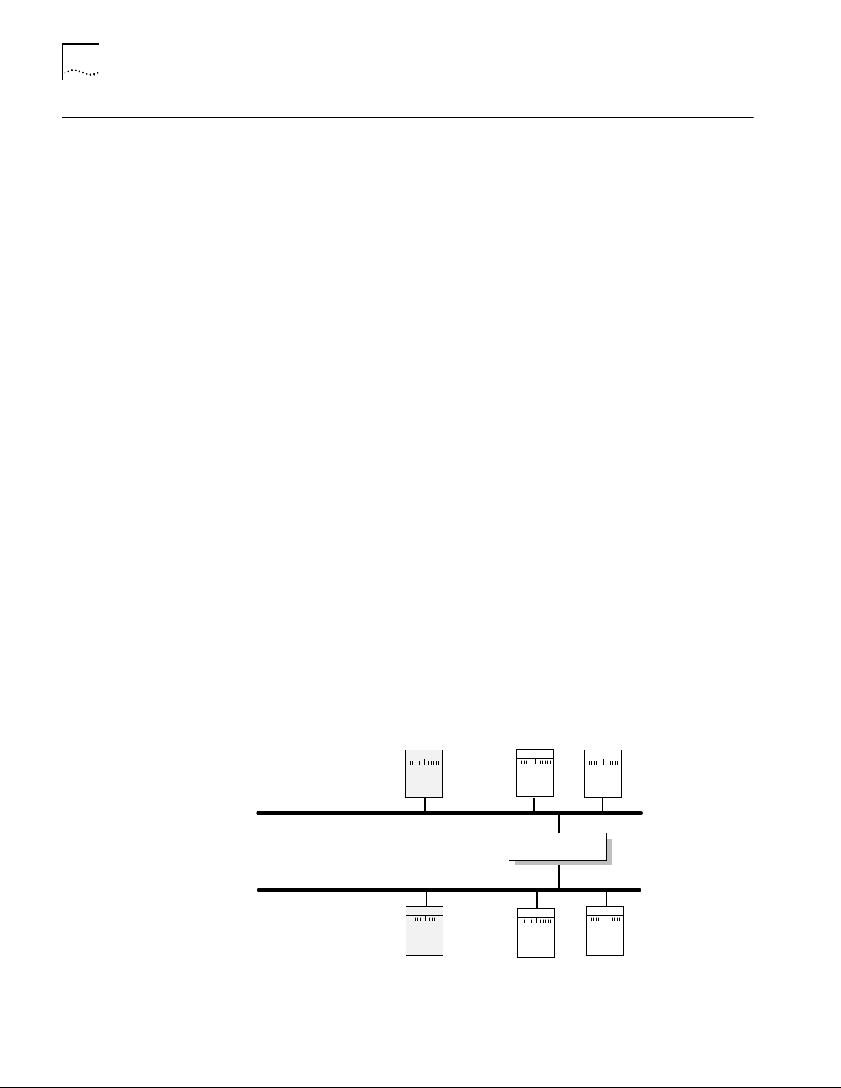
6-20 CHAPTER 6: CONFIGURING BASIC SETTINGS
Assigning Internet Addresses
Assigning Internet
Addresses to a Bridge
This section describes how to assign one or more Internet addresses to the system
using the NETaddr parameter in the IP Service. Before you assign an Internet
address, you must determine:
■ Whether you want your network to connect to the Internet, and how to obtain
a unique Internet address.
■ Whether you want to use the system as a bridge, a router, or a bridge/router.
■ Whether you need subnet addressing.
If you have already decided on these issues, proceed to “Assigning Internet
Addresses to a Bridge” on page 6-20 or to “Assigning Internet Addresses to a
Router” on page 6-21. If you need more information to make your decision, refer
to “Obtaining an Internet Address” on page 6-21 and to the subnet information
in the Using NETBuilder Family Software.
Even though a bridge does not route IP traffic, it needs an Internet address to
participate in network management and to be accessible from other devices
through Telnet or the SNMP.
When assigning an Internet address to an entire bridge, assign the address to
port 0 using:
SETDefault !0 -IP NETaddr = <IP address>
An Internet address assigned to port 0 is considered an Internet address for the
entire bridge.
The following example illustrates how to assign an Internet address to a bridge.
Example Figure 6-3 shows a configuration in which you need to assign an Internet address
to a bridge. Hosts A and B are two hosts belonging to the same IP network,
network 10. The IP host on Network A has an Internet address 10.0.0.1, and the
one on Network B has an Internet address 10.0.0.2. The bridge forwards packets
between these segments. To allow communication between the hosts and the
bridge, ports 1 and 2 must reside on the same network. Assigning the same
network number to two or more bridge ports is prohibited, so you must assign the
address to the entire bridge, entering a command similar to the following:
SETDefault !0 -IP NETaddr = 10.0.0.3
Segment A
Assign IP address 10.0.0.3 to Port 0
for the IP hosts to access the bridge
Segment B
IP address
= 10.0.0.1
IP address
= 10.0.0.2
IP
host
IP
host
A
B
IPX
host
IPX
host
OSI
host
Port 1
Bridge
Port 2
OSI
host
Figure 6-3 Assigning an IP Address to the Entire Bridge
After assigning an Internet address to the bridge, proceed to Chapter 1 in the
Using NETBuilder Family Software.
Page 57

Assigning Internet Addresses 6-21
Network A
Assign an IP address
to Port 1 so that the
bridge/router can boot
from the TFTP server
Assign an IP address
to Port 2 so that the
host can access the
bridge/router via Telnet
Network B
Bridge/Router
Port 1
Port 2
Host
TFTP
192.1.5.4
192.1.5.1 192.1.3.1
192.1.3.2
OSI
host
OSI
host
Assigning Internet
Addresses to a Router
Example In Figure 6-4, Networks A and B are two different IP networks, and the bridge/router
If the bridge/router is used to route IP traffic, you must configure the ports on which
IP packets are routed by assigning Internet addresses to them. You can assign
Internet addresses to individual ports using:
SETDefault !<port> -IP NETaddr = <IP address>
For more information, refer to the Reference for NETBuilder Family Software.
CAUTION: Do not assign an Internet address to port 0, or the IP routing function will
be disabled.
The next example illustrates how to assign Internet addresses to a bridge/router.
is used for routing IP packets and for bridging OSI packets. To assign an IP address to
port 1, enter a command similar to the following:
SETDefault !1 -IP NETaddr = 192.1.5.1
To assign an address to port 2, enter a command similar to the following:
SETDefault !2 -IP NETaddr = 192.1.3.1
Obtaining an
Internet Address
Figure 6-4 Assigning an IP Address to a Bridge/Router Port
For additional information on Internet addresses and subnet masks, refer to Using
NETBuilder Family Software. After assigning an Internet address or addresses to the
bridge/router, proceed to Chapter 1 in Using NETBuilder Family Software.
If you want to connect your TCP/IP network to the Internet, you must obtain a
unique address from the central authority, the InterNIC. This central authority
provides the following services:
■ Registration Services
Assists in registering networks and domains, and assigns network numbers and
other entities to the Internet community.
■ Directory and Database Services
Maintains lists of FTP sites, various types of servers available on the Internet,
white and yellow page directories, library catalogs, and data archives. For more
information, phone (908) 668-6587 or use network mail
(admin@ds.internic.net).
■ Information Services
Offers information about how to get connected to the Internet, pointers to
network tools and resources, and seminars on various topics held in locations
around the country. For more information, phone (800) 444-4345 or use
network mail (info@internic.net).
Page 58

6-22 CHAPTER 6: CONFIGURING BASIC SETTINGS
The Registration Service of the InterNIC assigns a globally unique network number ,
leaving responsibility for assigning a unique local host number to the network
administrator.
To obtain a unique Internet address, contact the following organization:
Network Solutions
Attn: InterNIC Registration Services
505 Huntmar Park Drive
Herndon, VA 22070
1-703-742-4777
800-444-4345 (Referral Desk)
Network mail: HOSTMASTER@RS.INTERNIC.NET
For customers in Europe (including the former Soviet Union and the Middle East),
contact the Reseaux IP European (RIPE) Network Coordination Center in the
Netherlands using telephone number 3120592 5065.
All other customers abroad should contact Network Solutions at the telephone
number given above for assistance in locating network providers in your region.
If you do not plan to be connected to the Internet, you can assign network
addresses on your own. However, if you plan on accessing the Internet in the
future, you may want to apply for an Internet network address so you will not
have to change network addresses when you make the connection.
Setting Up the Simple Network Management Protocol
After obtaining your Internet address, refer to “Assigning Internet Addresses to a
Bridge” on page 6-20 or to “Assigning Internet Addresses to a Router” on
page 6-21. For additional information on Internet addresses and subnets, refer to
Using NETBuilder Family Software.
The NETBuilder II bridge/router participates in different types of network
management activities. Most management activities require configuration because
they are disabled by default. The bridge/router manages networks in the following
ways:
■ Configuring and monitoring from a UNIX or Windows network management
station using Transcend Enterprise Manager
■ Remote upgrade management using the NETBuilder Remote Upgrade
Management Utilities supplied on CD-ROM with every NETBuilder release
■ Building network maps (netmaps)
This guide does not describe in detail how to set up the SNMP Service. Refer to
Using NETBuilder Family Software and Reference for NETBuilder Family Software
for more information.
SNMP allows you to modify and display some NETBuilder parameters from a
network management station. You do not need to attach a terminal to the
bridge/router console port to change its configuration. To implement SNMP, follow
specifications in RFC 1155, RFC 1157, and RFC 1213. System parameters
described in RFC 1213 and 3Com extended parameters can be accessed from the
host.
Page 59

NETBuilder Security 6-23
Modifying SNMP
Parameters
To enable SNMP read/write access, you need to modify two parameters in the
SNMP Service: COMmunity and MANager.
The COMmunity parameter is an SNMP Service parameter that modifies the list of
communities. For information on how to use the COMmunity parameter, refer to
Using NETBuilder Family Software and to Reference for NETBuilder Family
Software.
By default, the community name “ANYCOM” exists with read access to the
management information base (MIB) variables and allows unrestricted access to
the bridge/router. To ensure that access is available only to the proper system
administrator, 3Com recommends that you delete the “ANYCOM” community
name, and add the appropriate community string and the IP address of the
manager.
To modify SNMP parameters, follow these steps:
1 Delete the default community string “ANYCOM” by entering:
DELete -SNMP COMmunity “ANYCOM”
2 Configure at least one new community string with read/write access.
For example:
ADD -SNMP COMmunity “private” TRiv RW AL1
3 Add other community strings with read-only access as required.
For example:
ADD -SNMP COMmunity “public” TRiv RO AL1
4 Cr eate a new manager with r ead/write access to the NETBuilder bridge/r outer. For
security reasons, limit the number of network management stations.
For example:
ADD -SNMP MANager “private” 129.213.224.1 255.255.0
5 Enable the SNMP service by entering:
SETDefault -SNMP CONTrol = (Manage, Trap)
NETBuilder Security NETBuilder security can be obtained many ways including limiting the access to a
particular network or by limiting the access to certain files. Limiting access to a
particular network can be accomplished by building Internet firewalls. Limiting
access to particular files can be accomplished by using certain commands and
parameters.
Building Firewalls for
Security
A firewall allows users inside a private network to have outbound access, while
restricting outside users from inbound access. For more conceptual information
about firewall and its capabilities, and details on how to configure firewalls, refer
to Using NETBuilder Family Software. For a description and syntax of the various
firewall service parameters, refer to Reference for NETBuilder Family Software.
Page 60

6-24 CHAPTER 6: CONFIGURING BASIC SETTINGS
Security Commands and
Parameters
To make sure that some designated files are accessible only to the system
administrator, use the following commands and parameters:
■ NetAccess
This parameter is a SYS Service parameter that determines how a
bridge/router can be accessed from another device on the network. For
information on how to use the NetAccess parameter, refer to Using
NETBuilder Family Software and to Reference for NETBuilder Family Software.
■ SysPassWord
This command brings up a menu allowing you to specify the password for
the Network Manager and User privilege levels. For information on how to
use the SysPassWord command, refer Reference for NETBuilder Family
Software.
■ RemoteManager
This parameter is a SYS Service parameter that specifies the Internet
addresses of devices that can connect to the bridge/router through the
REMote command. For information on how to use the RemoteManager
parameter, refer to Using NETBuilder Family Software and to Reference for
NETBuilder Family Software.
■ COMmunity
This parameter is an SNMP Service parameter that modifies the list of
communities. For information on how to use the COMmunity parameter,
refer to Using NETBuilder Family Software and to Reference for NETBuilder
Family Software.
What Next? You are now ready to refer to Using NETBuilder Family Software to configure your
bridge/router for your specific network needs.
Page 61
BOOTING THE NETBUILDER II CEC
A
Booting from a TFTP/FTP Server
Installing NETBuilder
Software on the
UNIX-based Network
Management Station
20 S
If you do not have a flash memory drive or want to manage the software for one
or more bridge/routers on a centralized server, you can boot from a Trivial File
Transfer Protocol (TFTP) server. Configuration files can be accessed from the same
workstation running a File Transfer Protocol (FTP) server program.
Network boot is not supported by the NETBuilder II bridge/routers with the DPE
modules installed.
When you set up your NETBuilder bridge/router for network boot, you must
configure your bridge/router to boot from a particular server by specifying the IP
address of that server to the bridge/router. If you do not want to specify a
particular server , you may configur e your NETBuilder II bridge/router to use BOOTP,
which discovers available TFTP servers on the local network by broadcasting
BOOTP request packets. For more information about BOOTP, refer to Reference for
NETBuilder Family Software.
This section describes how to install NETBuilder II bridge/router software on a
UNIX-based network management station.
Prerequisites
To install the NETBuilder II bridge/router software image from a CD-ROM, the
CD-ROM drive must reside either locally on the network management station or
on another system on the network.
YSTEM FROM THE NETWORK
Before installing version 10.1 software from a CD-ROM, check that:
■ Your network management station is running Solaris 2.4 or 2.5x, SunOS 4.1.4,
HP-UX 9.0.5, 10.10 or 10.20, or IBM AIX 3.2.5, 4.1.4 or 4.2.
To verify the operating system environment you are running, enter:
uname -a
The version message will refer to Solaris 2.5x as SunOS 5.5.
■ You know the root password.
■ There is sufficient disk space on the network management station for the
amount of software you are installing.
Minimal disk storage requirements are dependent on the number of
NETBuilder systems being installed. For dual image support allocate 40 MB
for the NETBuilder Upgrade Management Utilities software image. For single
image support, allocate 4 MB for each NETBuilder II system.
■ The NETBuilder Upgrade Management Utilities released with this software
package have been installed on the network management station. Refer to
Upgrading NETBuilder Family Software for more information.
Page 62

A-2 APPENDIX A: BOOTING THE NETBUILDER II CEC 20 SYSTEM FROM THE NETWORK
Installing
NETBuilder Software
on the UNIX NMS
To install the NETBuilder software, follow these steps:
1 Ensure that the TFTP server on the network management station is running and
has been correctly configured.
2 Mount the version 10.1 software CD-ROM on the network management
station. For mount instructions for your specific UNIX operating system, refer to
Upgrading NETBuilder Family Software.
3 Set environmental variables with the location of NETBuilder Upgrade
Management Utilities. (These variables depend on the UNIX shell that is installed
at your site.)
■ If you are using a C-shell (csh), at the prompt enter:
source /usr/3Com/common/data/.login-bcm
■ If you are using a Bourne (sh) or Korn (ksh) shell, at the prompt enter:
. /usr/3Com/common/data/.profile-bcm
4 Ensure that you are using the version of the NETBuilder Upgrade Management
Utilities that shipped with your software upgrade. To check the version you have
installed, enter:
bcmdiagnose -h
The version of the installed utilities is displayed in the following message:
bcmdiagnose version 10.1. Copyright 3Com Corporation 1996
If the version of the utilities you have installed differs from the version shipped
with your software package, you must first install the utilities shipped with your
software package.
In the next step, the bcminstall utility extracts the files from the CD-ROM and
installs them on the network management station hard disk in the
/tftpboot/image/<platform>/ SW|FW/<version> /<pkg> directory. For example,
the software may be installed in the /tftpboot/image/NBII/SW/101/FF directory. If
there is insufficient space on the disk, you can link /tftpboot to another disk.
5 Using the NETBuilder Upgrade Management Utilities, install the NETBuilder
software from the CD-ROM (the default) by entering:
bcminstall
The optional path parameter may also be used to install on a network
management station that has two or more drives connected as well as for
installing from a remote CD-ROM drive. You must explicitly specify the second
CD-ROM drive.
To install a NETBuilder package from a second CD-ROM drive on a Solaris
machine, enter:
bcminstall -cdrom /cdrom/cdrom1/image
After the installation is complete, the screen shows an inventory of all NETBuilder
packages installed, including previous versions you have installed.
Page 63

Booting from a TFTP/FTP Server A-3
Setting Up a Unique
Configuration File
Directory on a
TFTP/FTP Server
The NETBuilder II system accesses both configuration files and multiprocessor (MP)
images from a unique directory on the network management station using TFTP. MP
images (MP6e.29k or MPatm) are always in /TFTPboot/image/NBII/SW/<release>/FF.
Configuration files on the network management station exist only when the user
does a bcmbackup and they are always stored in the following directory:
/tftpboot/image/<platform>/sw/version<package>.
To set up this unique directory, follow these steps:
1 For each NETBuilder II bridge/router, you must create a directory for these files
with appropriate read/write permissions.
For example, enter:
mkdir /tftpboot/configs/101/NBIICA
2 If your NETBuilder II bridge/router is using MP modules, you must copy these
images from the location on the network management station where they were
installed during the CD-ROM installation procedure.
These files are mp6e.29k and mpatm.29k. They reside in a default directory
represented by /tftpboot/image/NBII/SW/<version>/<pkg>.
For example, to use the 6-Port Ethernet module, enter:
cp /tftpboot/image/NBII/SW/101/FF/mp6e.29k
/tftpboot/configs/101/NBIICA
Setting the Primary
Boot Source
Set up the boot source to be a TFTP/FTP server accessed over a single Ethernet port
or FDDI port (FDDILink ports are not supported).
See Table A-1 for additional boot source parameter settings, such as those related
to booting over a token ring port, an HSS port using PPP, or a multiport Ethernet
module.
To set the primary boot source, follow these steps:
1 From the NETBuilder monitor prompt, enter:
SF
The System Configuration menu is displayed.
2 Select the Primary Boot Source option.
The Primary Boot Source menu is displayed.
3 Select the Boot Device option, and set the Boot Device to Network.
You are then prompted to set the slot number and boot filename.
4 Enter the slot number of the module that is used to reach your TFTP server.
If you have a 4-Slot chassis, your options are 1 through 4. If you have an 8-Slot
chassis, your options are 1 through 8.
5 Enter the boot filename by entering the directory path and filename relative to
the “tftpboot” directory where the CEC 20 boot image resides.
For example, enter:
/image/NBII/SW/101/FF/boot.29k
6 Enter Q to return to the Primary Boot Source menu.
Page 64

A-4 APPENDIX A: BOOTING THE NETBUILDER II CEC 20 SYSTEM FROM THE NETWORK
7 Enter 2 and set the Primary Config File Source to Boot Device.
You will be prompted for the Default directory for your configuration files.
8 Enter Q to return to the Primary Boot Source menu.
9 Select the Boot Protocol option, and set the Primary Boot Protocol to TFTP.
You are then prompted to set the TFTP Address Discovery Protocol.
10 Enter Q to return to the Primary Boot Source menu.
11 Select the IP Addresses option, and enter the primary IP addresses assigned to
your client, boot server, gateway, remote file server, and subnet mask.
12 Enter Q twice to return to the Primary Boot Source menu.
13 Select the FTP Login option, and enter the username and password to be used
by FTP.
The password is not displayed on the console when you type it.
14 Exit the SysconF menu system by typing Q repeatedly.
15 Reboot the system by simultaneously pressing both Reset buttons on the front
panel, or by typing RS at the monitor prompt.
More Boot Options Table A-1 summarizes other parameters you may need to configure, including
parameters you need to boot from a TFTP server over a token ring port, HSS port
using PPP, or multiport Ethernet module.
Table A-1 Additional TFTP Primary Boot Source Parameters
Parameter Configuration
Boot Device:
Network
MP Module
Parameters
(continued)
Interface Number
You are prompted with this field only if an Ethernet 2-Port or Ethernet 6-Port
module resides in the slot. Make sure this parameter is set to the appropriate
interface (A or B or A–F). The default is A.
You need to configure this parameter only if the TFTP server is reachable
through an HSS port running PPP or a token ring port.
HSS port running PPP
If your boot source is reachable through an HSS port running PPP, you are
prompted to configure the following fields:
■ HSS Baud Rate
This setting must correspond to your serial line setting.
■ HSS Clock Source
Set this parameter appropriately (the default setting is external).
■ HSS Connector Type
Set this parameter to the connector that the server is reachable through
(the default is V.35).
■ HSS Protocol
Select PPP.
■ HSS WAN Password
Leave this field empty.
Page 65

Booting from a TFTP/FTP Server A-5
Table A-1 Additional TFTP Primary Boot Source Parameters (continued)
Parameter Configuration
Token ring port
If your boot source is reachable through a token ring port, you are prompted
to configure the following field:
■ Token Ring Speed
This setting must correspond to the token ring line setting (the default is
4 Mbps).
■ Token Ring Baud Rate
Make sure the setting of this field matches that of your token ring line.
Boot Protocol Make sure the Boot Protocol is set to TFTP.
If you are configuring your bridge/router to use TFTP only, set the Address
Discovery Protocol to Local Configured Addresses.
If you are configuring your bridge/router to use TFTP and BOOTP, set the
Address Discovery Protocol to BOOTP.
Boot Sources Make sure the Boot Sources are set to Primary and Secondary.
MAC Address Make sure this parameter is set to the CEC 20 MAC address.
ARP Format If your boot source is reachable through a token ring port, make sure that the
setting of this parameter agrees with the Address Resolution Protocol (ARP)
format used on your token ring network: noncanonical.
What Next? You may set up the Simple Network Management Protocol (SNMP) to allow
network management of the bridge/router. For information on this service, refer
to “Setting Up the Simple Network Management Protocol” on page 6-22.
Refer to Chapter 6 to configure basic settings.
To set other boot options, refer to the SysconF appendix in Reference for
NETBuilder Family Software.
Page 66

Page 67

B
TECHNICAL SUPPORT
3Com provides easy access to technical support information through a variety of
services. This appendix describes these services.
Information contained in this appendix is correct at time of publication. For the very
latest, we recommend that you access 3Com Corporation’s World Wide Web site.
Online Technical Services
World Wide Web Site Access the latest networking information on 3Com Corporation’s World Wide
3Com Bulletin Board
Service
3Com offers worldwide product support 24 hours a day, 7 days a week, through
the following online systems:
■ World Wide Web site
■ 3Com Bulletin Board Service (3ComBBS)
■ 3ComFacts
■ 3ComForum on CompuServe online service
Web site by entering our URL into your Internet browser:
http://www.3com.com/
This service features the latest information about 3Com solutions and
technologies, customer service and support, news about the company,
Net Age
3ComBBS contains patches, software, and drivers for all 3Com products, as well
as technical articles. This service is available through analog modem or digital
modem (ISDN) 24 hours a day, 7 days a week.
Access by Analog Modem
To reach the service by modem, set your modem to 8 data bits, no parity, and
1 stop bit. Call the telephone number nearest you:
SM
automated fax service
®
Magazine, and more.
Country Data Rate Telephone Number
Australia up to 14400 bps 61 2 9955 2073
Brazil up to 14400 bps 55 11 547 9666
France up to 14400 bps 33 1 6986 6954
Germany up to 28800 bps 4989 62732 188
Hong Kong up to 14400 bps 852 2537 5608
Italy (fee required) up to 14400 bps 39 2 27300680
Japan up to 14400 bps 81 3 3345 7266
(continued)
Page 68

B-2 APPENDIX B: TECHNICAL SUPPORT
Country Data Rate Telephone Number
Mexico up to 28800 bps 52 5 520 7853
P.R. of China up to 14400 bps 86 10 684 92351
Singapore up to 14400 bps 65 534 5693
Taiwan, R.O.C. up to 14400 bps 886 2 377 5840
U.K. up to 28800 bps 44 1442 438278
U.S.A. up to 28800 bps 1 408 980 8204
Access by Digital Modem
ISDN users can dial in to 3ComBBS using a digital modem for fast access up to
56 Kbps. To access 3ComBBS using ISDN, use one of the following numbers:
408 654 2706 or 408 654 2703
3ComFacts Automated
Fax Service
3Com Corporation’s interactive fax service, 3ComFacts, provides data sheets,
technical articles, diagrams, and troubleshooting instructions on 3Com products
24 hours a day, 7 days a week.
Call 3ComFacts using your Touch-T one telephone using one of these international
access numbers:
Country Telephone Number
U.K. 44 1442 438279
U.S.A. 1 408 727 7021
Local access numbers are available within the following countries:
Telephone
Country
Australia 1800 678 515 Netherlands 06 0228049
Belgium 0800 71279 New Zealand 0800 446 398
Denmark 800 17319 Norway 800 11062
Finland 98 001 4444 Portugal 0505 442 607
France 05 90 81 58 Russia (Moscow only) 956 0815
Germany 0130 81 80 63 Singapore 800 6161 463
Hong Kong 800 933 486 Spain 900 964 445
Italy 1678 99085 Sweden 020 792954
Malaysia 1800 801 777 U.K. 0800 626403
Number
Country
Telephone
Number
3ComForum on
CompuServe Online
Service
3ComForum contains patches, software, drivers, and technical articles about all
3Com products, as well as a messaging section for peer support. To use
3ComForum, you need a CompuServe account.
To use 3ComForum:
1 Log on to your CompuServe account.
2 Type
go threecom
3 Press [Return] to see the 3ComForum main menu.
Page 69

Support from Your Network Supplier B-3
Regional Sales Office Telephone Number
3Com Corporation
P.O. Box 58145
5400 Bayfront Plaza
Santa Clara, California
95052-8145
U.S.A.
800 NET 3Com or
1 408 764 5000
408 764 5001 (fax)
3Com Asia Limited
Australia
Hong Kong
India
Indonesia
Japan
Korea
Malaysia
New Zealand
Philippines
P.R. of China
Singapore
Taiwan, R.O.C.
Thailand
61 2 9937 5000 (Sydney)
61 3 9866 8022 (Melbourne)
852 2501 1111
91 11 644 3974
62 21 572 2088
81 6 536 3303 (Osaka)
81 3 3345 7251 (Tokyo)
82 2 319 4711
60 3 732 7910
64 9 366 9138
632 892 4476
8610 68492568 (Beijing)
86 21 63501581 (Shanghai)
65 538 9368
886 2 377 5850
662 231 8151 5
3Com Benelux B.V.
Belgium
Netherlands
32 2 725 0202
31 30 6029700
3Com Canada
Calgary
Edmonton
Montreal
Ottawa
Toronto
Vancouver
403 265 3266
403 423 3266
514 683 3266
1 613 566 7055
416 498 3266
604 434 3266
3Com France 33 1 69 86 68 00
3Com GmbH
Austria
Czech Republic/Slovak Republic
Germany
(Central European HQ)
Hungary
Poland
Switzerland
43 1 513 4323
420 2 21845 800
49 30 34 98790 (Berlin)
49 89 627320 (Munich)
36 1 250 83 41
48 22 6451351
41 31 996 14 14
(continued)
Regional Sales Office Telephone Number
Support from Your Network Supplier
If additional assistance is required, contact your network supplier. Many suppliers
are authorized 3Com service partners who are qualified to provide a variety of
services, including network planning, installation, hardware maintenance,
application training, and support services.
When you contact your network supplier for assistance, have the following
information ready:
■ A list of system hardware and software, including revision levels
■ Diagnostic error messages
■ Details about recent configuration changes, if applicable
If you are unable to contact your network supplier, see the following section on
how to contact 3Com.
Support from 3Com If you are unable to receive support from your network supplier, technical support
contracts are available from 3Com.
Contact your local 3Com sales office to find your authorized service provider using
one of these numbers:
Page 70

B-4 APPENDIX B: TECHNICAL SUPPORT
Regional Sales Office Telephone Number
3Com Iberia
Portugal
Spain
3Com Ireland 353 1 820 7077
3Com Latin America
U.S. Headquarters
Northern Latin America
Argentina
Brazil
Chile
Colombia
Mexico
Peru
Venezuela
Returning Products
for Repair
351 1 3404501
34 1 383 17 00
408 326 2093
305 261 3266 (Miami, Florida)
541 312 3266
55 11 5181 0869
562 633 8935
571 629 4110
52 5 520 7841/7847
51 1 221 5399
58 2 953 8122
Before you send a product directly to 3Com for repair, you must first obtain a
Return Materials Authorization (RMA) number. Products sent to 3Com without
RMA numbers will be returned to the sender unopened, at the sender’s expense.
To obtain an RMA number, call or fax:
Country Telephone Number Fax Number
U.S.A. and Canada 1 800 876 3266, option 2 408 764 7120
Latin America 1 408 326 2927 408 764 7120
Europe, South Africa, and Middle East 44 1442 438125 44 1442 435822
Elsewhere 1 408 326 2926 1 408 764 7120
Regional Sales Office Telephone Number
3Com Mediterraneo
Italy
3Com Middle East 971 4 349049
3Com Nordic AB
Denmark
Finland
Norway
Sweden
3Com Russia 007 095 258 09 40
3Com Southern Africa 27 11 807 4397
3Com UK Ltd. 44 131 240 2900 (Edinburgh)
39 2 253011 (Milan)
39 6 5279941 (Rome)
45 39 27 85 00
358 0 435 420 67
47 22 58 47 00
46 8 632 56 00
44 161 873 7717 (Manchester)
44 162 889 7000 (Marlow)
08/04/97
Page 71

INDEX
Numerics
3Com Bulletin Board Service
(3ComBBS)
3Com sales offices B-3
3Com URL B-1
3ComFacts B-2
3ComForum B-2
B-1
A
abbreviated command syntax 6-5, 6-6
address formats
media
AppleTalk
Frame Relay 6-13
ISDN 6-14
MAC 6-12
SMDS 6-13
X.25 6-13
network layer
DECnet
Internet 6-14
IP 6-14
IPX 6-15
OSI 6-15
VIP 6-15
XNS 6-16
addresses
Internet, assigning to
bridge/router
IP, obtaining 6-21
media 6-12
specifying 6-9, 6-12
aliases 6-8
AppleTalk address format 6-14
ARP Format parameter 4-6, A-5
attributes, parameter 6-9
6-14
6-14
6-20
B
Boot Device parameter 4-6, A-4
Boot Monitor 3-1
Boot command 3-1
BT command 3-1
Boot Protocol parameter 4-6, A-5
boot source, setting up Primary 3-2, 5-1,
A-3
bridge/router
assigning IP addresses
logging on 3-2, 4-8, 5-1, 6-1
security 6-24
setting
system administrator
information
time and date 6-18
user interface 6-2
BT command 3-2
bulletin board service B-1
6-20
6-19
C
CEC 20 1-1
command-line interface
assigning
names
6-10
numeric values 6-10
strings 6-10
attribute assignment rules 6-9
entering service names 6-7
help 6-16
privilege level 6-9
short cuts
using aliases
using history substitution 6-8
specifying values, set members, or
addresses
syntax
abbreviated
full form 6-4, 6-6
symbols used 6-5
variations 6-7, 6-11
using 6-3
when to use 6-2
Commands
Boot
3-1
BT 3-1
menu 6-2
ReBoot 3-3
SysconF 3-2
SysPassWord 6-24
commands
accessing
history of substitution 6-8
MEnu 6-2, 6-3
Communication Engine Card, See CEC 20
COMmunity parameter
CompuServe B-2
Configuration files 3-3
configuration parameters 6-17
conventions
notice icons, About This Guide
string values 6-10
text, About This Guide 2
values
names
numerics 6-10
CurrentPorts parameter 6-7
CurrentServices parameter 6-7
6-8
6-9
6-5, 6-6
6-2
6-24
2
6-10
D
DECnet address format 6-14
Default primary boot source 3-1
disk space, system requirements A-1
displays, ports 6-7
DPE 1-1
Dual Processor Engine, See DPE 40 and DPE
80
Dump Destination parameter
System Configuration menu
3-3
E
event designators 6-8
EZBuilt preassembled NETBuilder II 1-1
F
fax service. See 3ComFacts
firmware parameters
ARP Format
Boot Device 4-6, A-4
Boot Protocol 4-6, A-5
I/O Board 4-6, A-4
MAC Address 4-6, A-5
formats, address 6-12
Frame Relay address format 6-13
4-6, A-5
H
help menu 6-16
history substitution 6-8
I
I/O Board parameter 4-6, A-4
Initial Boot 2-1, 4-1
Installing software 2-1, 4-1
Internet address
assigning to a bridge
assigning to bridge/router 6-21
format 6-14
internet address
obtaining
IP routing setup 6-16
IPX address format 6-15
ISDN
address format
syntax variation 6-11
6-21
6-20
6-14
L
logging on
as root
3-2, 4-8, 5-1, 6-1, A-2
from console 6-1
M
MAC address format 6-12
MAC Address parameter 4-6, A-5
media addresses 6-12
MEnu command 6-3
Page 72

2 INDEX
menu-driven interface
accessing
limitations 6-3
limitations (Note) 6-3
menus, accessing 6-3
6-3
N
names
assigning
service, entering 6-7
naming restrictions, port/path 6-11
NetAccess parameter 6-24
NETBuilder II system
disk space requirements
EZBuilt Preassembled 1-1
network layer addresses 6-14
network management 6-22
network management station
PC-based
UNIX-based 4-2
Network Manager privilege level
changing password
obtaining 6-17
network service access point. See NSAP
network supplier support
NSAP 6-15
numeric values, assigning 6-10
6-10
A-1
4-5
6-18
B-3
O
online help 6-16
online technical services B-1
OSI address format 6-15
P
parameters
firmware
information displayed on selection 6-3
values
passwords, changing 6-18
paths
naming restrictions
using instance identifiers 6-11
ports
naming restrictions
syntax conventions 6-8
using instance identifiers 6-11
primary boot source parameters, TFTP A-4
privilege level
changing
changing SNMP access to files 6-23
obtaining Network Manager 6-17
to access commands and
4-6, A-4, A-5
assigning
storing 6-17
6-18
parameters
6-10
6-11
6-11
6-9
Q
question mark(?) help command 6-16
R
ReBoot command 3-3
RemoteManager parameter 6-24
repeating displayed commands 6-8
restrictions, naming 6-11
returning products for repair B-4
root login 4-8, 6-1, A-2
S
security 6-24
service names, entering 6-7
services, selecting 6-2
set members, specifying 6-9
Simple Network Management Protocol. See
SNMP
SNMP
changing manager access to files
displaying/modifying system
parameters
software, installing
from PC-based network management
station
from UNIX-based network
management station
strings
case-sensitivity
entering 6-10
using as instance identifiers 6-11
syntax, command
abbreviated
assigning parameter values 6-10
full form 6-4, 6-6
ISDN variation 6-11
symbols used 6-5
variations 6-7
SysconF command 3-2
SysPassWord command 6-24
system administrator information,
setting
System Configuration menu 3-3
6-19
Dump Destination parameter 3-3
6-22
4-5
4-2
6-10
6-5, 6-6
6-23
T
technical support
3Com URL
bulletin board service B-1
CompuServe service B-2
fax service B-2
network suppliers B-3
product repair B-4
time and date, setting 6-18
B-1
U
URL B-1
user interface
command-line
menu-driven 6-2
6-2
V
values
assigning numeric
specifying 6-9
storing parameter 6-17
syntax for assigning 6-10
VIP address format 6-15
virtual ports
displaying
functionality (Note) 6-8
syntax conventions 6-8
6-10
6-7
W
World Wide Web (WWW) B-1
X
X.25 address format 6-13
XNS address format 6-16
Page 73

3Com Corporation LIMITED WARRANTY
HARDWARE 3Com warrants its hardware products to be free from defects in workmanship and materials, under normal use and service,
for the following lengths of time from the date of purchase from 3Com or its Authorized Reseller:
Network adapters Lifetime
Other hardware products (unless specified above) 1 year
Spare parts and spares kits 90 days
If a product does not operate as warranted above during the applicable warranty period, 3Com shall, at its option and
expense, repair the defective product or part, deliver to Customer an equivalent product or part to replace the defective
item, or refund to Customer the purchase price paid for the defective product. All products that are replaced will become
the property of 3Com. Replacement products may be new or reconditioned. Any replaced or repaired product or part has a
ninety (90) day warranty or the remainder of the initial warranty period, whichever is longer.
3Com shall not be responsible for any software, firmware, information, or memory data of Customer contained in, stored
on, or integrated with any products returned to 3Com for repair, whether under warranty or not.
SOFTWARE 3Com warrants that the software programs licensed from it will perform in substantial conformance to the program
specifications therefor for a period of ninety (90) days from the date of purchase from 3Com or its Authorized Reseller.
3Com warrants the media containing software against failure during the warranty period. No updates are provided. 3Com’s
sole obligation with respect to this express warranty shall be (at 3Com’s discretion) to refund the purchase price paid by
Customer for any defective software products, or to replace any defective media with software which substantially conforms
to 3Com’s applicable published specifications. Customer assumes responsibility for the selection of the appropriate
applications program and associated reference materials. 3Com makes no warranty or representation that its software
products will work in combination with any hardware or applications software products provided by third-parties, that the
operation of the software products will be uninterrupted or error free, or that all defects in the software products will be
corrected. For any third-party products listed in the 3Com software product documentation or specifications as being
compatible, 3Com will make reasonable efforts to provide compatibility, except where the noncompatibility is caused by a
“bug” or defect in the third-party’s product.
STANDARD WARRANTY
S
ERVICE
Standard warranty service for hardware products may be obtained by delivering the defective product, accompanied by a
copy of the dated proof of purchase, to 3Com’s Corporate Service Center or to an Authorized 3Com Service Center during
the applicable warranty period. Standard warranty service for software products may be obtained by telephoning 3Com’s
Corporate Service Center or an Authorized 3Com Service Center, within the warranty period. Products returned to 3Com’s
Corporate Service Center must be pre-authorized by 3Com with a Return Material Authorization (RMA) number marked on
the outside of the package, and sent prepaid, insured, and packaged appropriately for safe shipment. The repaired or
replaced item will be shipped to Customer, at 3Com’s expense, not later than thirty (30) days after receipt of the defective
product by 3Com.
WARRANTIES EXCLUSIVE IF A 3COM PRODUCT DOES NOT OPERATE AS WARRANTED ABOVE, CUSTOMER’S SOLE REMEDY FOR BREACH OF THAT
WARRANTY SHALL BE REPAIR, REPLACEMENT, OR REFUND OF THE PURCHASE PRICE PAID, AT 3COM’S OPTION. TO THE
FULL EXTENT ALLOWED BY LAW, THE FOREGOING WARRANTIES AND REMEDIES ARE EXCLUSIVE AND ARE IN LIEU OF ALL
OTHER WARRANTIES, TERMS, OR CONDITIONS, EXPRESS OR IMPLIED, EITHER IN FACT OR BY OPERATION OF LAW,
STATUTORY OR OTHERWISE, INCLUDING WARRANTIES, TERMS, OR CONDITIONS OF MERCHANTABILITY, FITNESS FOR A
PARTICULAR PURPOSE, AND SATISFACTORY QUALITY. 3COM NEITHER ASSUMES NOR AUTHORIZES ANY OTHER PERSON
TO ASSUME FOR IT ANY OTHER LIABILITY IN CONNECTION WITH THE SALE, INSTALLATION, MAINTENANCE, OR USE OF ITS
PRODUCTS.
3COM SHALL NOT BE LIABLE UNDER THIS WARRANTY IF ITS TESTING AND EXAMINATION DISCLOSE THAT THE ALLEGED
DEFECT IN THE PRODUCT DOES NOT EXIST OR WAS CAUSED BY CUSTOMER’S OR ANY THIRD PERSON’S MISUSE,
NEGLECT, IMPROPER INSTALLATION OR TESTING, UNAUTHORIZED ATTEMPTS TO REPAIR OR MODIFY, OR ANY OTHER
CAUSE BEYOND THE RANGE OF THE INTENDED USE, OR BY ACCIDENT, FIRE, LIGHTNING, OR OTHER HAZARD.
LIMITATION OF LIABILITY TO THE FULL EXTENT ALLOWED BY LAW, 3COM ALSO EXCLUDES FOR ITSELF AND ITS SUPPLIERS ANY LIABILITY, WHETHER
BASED IN CONTRACT OR TORT (INCLUDING NEGLIGENCE), FOR INCIDENTAL, CONSEQUENTIAL, INDIRECT, SPECIAL, OR
PUNITIVE DAMAGES OF ANY KIND, OR FOR LOSS OF REVENUE OR PROFITS, LOSS OF BUSINESS, LOSS OF INFORMATION
OR DATA, OR OTHER FINANCIAL LOSS ARISING OUT OF OR IN CONNECTION WITH THE SALE, INSTALLATION,
MAINTENANCE, USE, PERFORMANCE, FAILURE, OR INTERRUPTION OF ITS PRODUCTS, EVEN IF 3COM OR ITS AUTHORIZED
RESELLER HAS BEEN ADVISED OF THE POSSIBILITY OF SUCH DAMAGES, AND LIMITS ITS LIABILITY TO REPAIR,
REPLACEMENT, OR REFUND OF THE PURCHASE PRICE PAID, AT 3COM’S OPTION. THIS DISCLAIMER OF LIABILITY FOR
DAMAGES WILL NOT BE AFFECTED IF ANY REMEDY PROVIDED HEREIN SHALL FAIL OF ITS ESSENTIAL PURPOSE.
Some countries, states, or provinces do not allow the exclusion or limitation of implied warranties or the limitation of
incidental or consequential damages for certain products supplied to consumers or the limitation for personal injury, so the
above limitations and exclusions may be limited in their application to you. This warranty gives you specific legal rights
which may vary depending on local law.
GOVERNING LAW This Limited Warranty shall be governed by the laws of the state of California.
3Com Corporation, 5400 Bayfront Plaza, Santa Clara, CA 95052-8145 (408) 764-5000
9/1/96
Page 74

 Loading...