

Page 1

www.2n.czFirmware
Version
2N SmartCom
®
Wireless Device Management over IP
User Manual
1.9.0
1.9.x
Page 2

The 2N TELEKOMUNIKACE joint-stock company is a Czech manufacturer and supplier of
telecommunications equipment.
The product family developed by 2N TELEKOMUNIKACE a.s. includes GSM gateways, private
branch exchanges (PBX), and door and lift communicators. 2N TELEKOMUNIKACE a.s. has
been ranked among the Czech top companies for years and represented a symbol of stability
and prosperity on the telecommunications market for almost two decades. At present, we
export our products into over 120 countries worldwide and have exclusive distributors on all
continents.
2N is a registered trademark of 2N TELEKOMUNIKACE a.s.. Any product and/or other
®
names mentioned herein are registered trademarks and/or trademarks or brands protected
by law.
2N TELEKOMUNIKACE administers the FAQ database to help you quickly find information and
to answer your questions about 2N products and services. On www.faq.2n.cz you can find
information regarding products adjustment and instructions for optimum use and procedures
„What to do if...“.
Declaration of Conformity
2N TELEKOMUNIKACE hereby declares that the 2N SmartCOM product complies with all
®
basic requirements and other relevant provisions of the 1999/5/EC directive. For the full
wording of the Declaration of Conformity see the CD-ROM enclosed and at www.2n.cz.
The 2N TELEKOMUNIKACE company is the holder of the ISO 9001:2009 certificate. All
development, production and distribution processes of the company are managed by this
standard and guarantee a high quality, technical level and professional aspect of all our
Page 3

Content
1. Product Overview . . . . . . . . . . . . . . . . . . . . . . . . . . . . . . . . . . 5
1.1 Product Description . . . . . . . . . . . . . . . . . . . . . . . . . . . . . . . . . . . . . . . . . . . . . . 6
1.2 Upgrade . . . . . . . . . . . . . . . . . . . . . . . . . . . . . . . . . . . . . . . . . . . . . . . . . . . . . . . 8
1.3 Terms and Symbols Used . . . . . . . . . . . . . . . . . . . . . . . . . . . . . . . . . . . . . . . . . 9
2. Description and Installation . . . . . . . . . . . . . . . . . . . . . . . . . . 10
2.1 Basic Version Description . . . . . . . . . . . . . . . . . . . . . . . . . . . . . . . . . . . . . . . . . . 11
2.2 PRO Version Description . . . . . . . . . . . . . . . . . . . . . . . . . . . . . . . . . . . . . . . . . . 13
2.3 Before You Start . . . . . . . . . . . . . . . . . . . . . . . . . . . . . . . . . . . . . . . . . . . . . . . . . 15
2.4 Mounting . . . . . . . . . . . . . . . . . . . . . . . . . . . . . . . . . . . . . . . . . . . . . . . . . . . . . . . 16
3. Function and Use . . . . . . . . . . . . . . . . . . . . . . . . . . . . . . . . . . 19
3.1 Putting in Operation . . . . . . . . . . . . . . . . . . . . . . . . . . . . . . . . . . . . . . . . . . . . . . 20
3.2 GSM LED Indicator . . . . . . . . . . . . . . . . . . . . . . . . . . . . . . . . . . . . . . . . . . . . . . . 21
3.3 Input and Output Circuits . . . . . . . . . . . . . . . . . . . . . . . . . . . . . . . . . . . . . . . . . . 22
3.4 Input Calibration . . . . . . . . . . . . . . . . . . . . . . . . . . . . . . . . . . . . . . . . . . . . . . . . . 27
4. Configuration by Terminal . . . . . . . . . . . . . . . . . . . . . . . . . . . 29
4.1 Configuration . . . . . . . . . . . . . . . . . . . . . . . . . . . . . . . . . . . . . . . . . . . . . . . . . . . 30
4.2 List of Supported AT Commands . . . . . . . . . . . . . . . . . . . . . . . . . . . . . . . . . . . . 32
5. Configuration by SMS . . . . . . . . . . . . . . . . . . . . . . . . . . . . . . . 58
6. Terminal Config . . . . . . . . . . . . . . . . . . . . . . . . . . . . . . . . . . . . 66
7. Control Panel . . . . . . . . . . . . . . . . . . . . . . . . . . . . . . . . . . . . . . 78
7.1 SC Server . . . . . . . . . . . . . . . . . . . . . . . . . . . . . . . . . . . . . . . . . . . . . . . . . . . . . . 79
7.2 Control Panel . . . . . . . . . . . . . . . . . . . . . . . . . . . . . . . . . . . . . . . . . . . . . . . . . . . 82
7.3 Control Panel Use . . . . . . . . . . . . . . . . . . . . . . . . . . . . . . . . . . . . . . . . . . . . . . . 88
8. AT API . . . . . . . . . . . . . . . . . . . . . . . . . . . . . . . . . . . . . . . . . . . 107
8.1 AT API Description . . . . . . . . . . . . . . . . . . . . . . . . . . . . . . . . . . . . . . . . . . . . . . . 108
8.2 Supported Commands . . . . . . . . . . . . . . . . . . . . . . . . . . . . . . . . . . . . . . . . . . . . 109
Page 4

9. User Defined Functions - UDF . . . . . . . . . . . . . . . . . . . . . . . . 117
9.1 UDF Description . . . . . . . . . . . . . . . . . . . . . . . . . . . . . . . . . . . . . . . . . . . . . . . . . 118
9.2 UDF Condition Setting . . . . . . . . . . . . . . . . . . . . . . . . . . . . . . . . . . . . . . . . . . . . 119
10. sc_config . . . . . . . . . . . . . . . . . . . . . . . . . . . . . . . . . . . . . . . . 128
11. Maintenance . . . . . . . . . . . . . . . . . . . . . . . . . . . . . . . . . . . . . 134
11.1 Firmware Upgrade (Update) . . . . . . . . . . . . . . . . . . . . . . . . . . . . . . . . . . . . . . . 135
11.2 Factory Default Reset . . . . . . . . . . . . . . . . . . . . . . . . . . . . . . . . . . . . . . . . . . . . 136
11.3 Repairs . . . . . . . . . . . . . . . . . . . . . . . . . . . . . . . . . . . . . . . . . . . . . . . . . . . . . . . 137
12. Technical Parameters . . . . . . . . . . . . . . . . . . . . . . . . . . . . . . 138
12.1 Technical Parameters for Basic Version . . . . . . . . . . . . . . . . . . . . . . . . . . . . . 139
12.2 Technical Parameters for PRO Version . . . . . . . . . . . . . . . . . . . . . . . . . . . . . . 141
13. Supplementary Information . . . . . . . . . . . . . . . . . . . . . . . . . 144
13.1 List of Abbreviations . . . . . . . . . . . . . . . . . . . . . . . . . . . . . . . . . . . . . . . . . . . . . 145
13.2 Regulations, Laws and Directives . . . . . . . . . . . . . . . . . . . . . . . . . . . . . . . . . . 146
13.3 General Instructions and Cautions . . . . . . . . . . . . . . . . . . . . . . . . . . . . . . . . . . 147
Page 5

1. Product Overview
In this section, we introduce the product, outline its application2N SmartCOM
®
options and highlight the advantages following from its use. The section also includes
safety precautions.
Here is what you can find in this section:
1.1 Product Description
1.2 Upgrade
1.3 Terms and Symbols Used
®
52N TELEKOMUNIKACE a.s., www.2n.cz
Page 6
1.1 Product Description
The GPRS communication unit is a new product developed and2N SmartCOM
®
manufactured to provide the maximum utility value, quality and reliability. We hope
you will be fully satisfied with the for a long time. Use 2N SmartCOM
®
2N
®
in accordance herewith for the purposes it was designed and SmartCOM
manufactured for.
is designed for Internet connection via the GPRS network and data2N SmartCOM
®
retransmission from peripherals connected to RS 232/485/M–Bus via the IP protocol
and GPRS network to a data requesting server or device. Two relay outputs can be
controlled and switched and parameters can be measured on two galvanically
connected inputs.
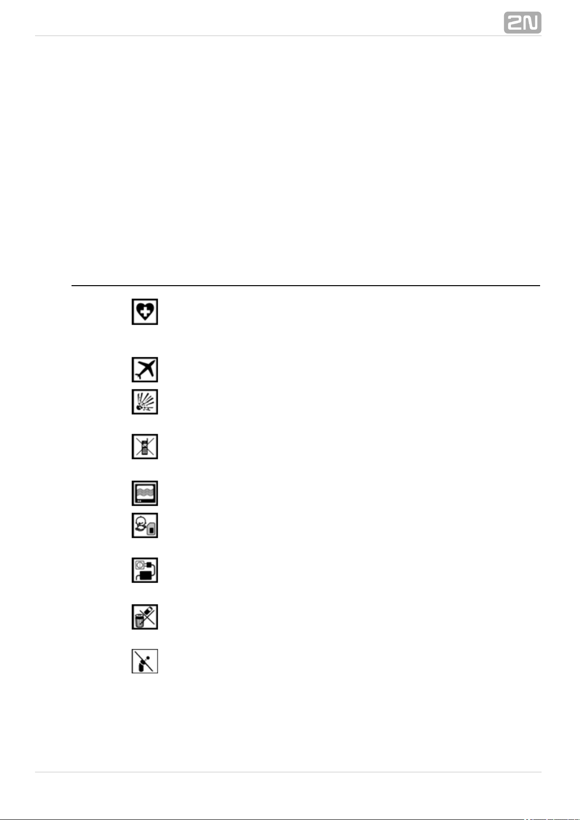
Safety Precautions
Do not switch on in the vicinity of medical apparatuses to2N SmartCOM
®
avoid interference. The minimum distance of the antenna and pacemakers should
be 0.5m at least.
Do not switch aboard a plane.2N SmartCOM
®
Do not switch near petrol stations, chemical facilities or2N SmartCOM
®
sites where explosives are used.
Any mobile telephone use prohibition based on RF energy radiation applies
to too.2N SmartCOM
®
may disturb the function of TV sets, radio sets and PCs.2N SmartCOM
®
Warning! contains components that can be swallowed by2N SmartCOM
®
small children (SIM card, antenna, etc.).
Never exceed the voltage value specified on the adapter. Check the available
voltage range before connecting to a different power supply.2N SmartCOM
®
When comes to the end of its operational life, dispose of it2N SmartCOM
®
in accordance with applicable regulations.
is equipped with an external antenna connector. The2N SmartCOM
®
antenna has to be located indoors for safety reasons.
®
62N TELEKOMUNIKACE a.s., www.2n.cz
Page 7

Warning
Do not place the unit near heat sources (such as space heaters, hot
air heaters, etc.).
2N SmartCOM® only works reliably under the conditions specified in
this User Manual. Any unauthorised interventions and/or changes in
use and operation may result in malfunction or destruction of the
product.
®
72N TELEKOMUNIKACE a.s., www.2n.cz
Page 8
1.2 Upgrade
The manufacturer reserves the right to modify in order to improve its2N SmartCOM
®
qualities.
Manual
Version
Changes in Documentation
1.0.0
The User Manual corresponds to FW version 2N SmartCOM
®
.1.0.x
1.1.0
The User Manual corresponds to FW version 2N SmartCOM
®
.1.1.x
1.3.0
The User Manual corresponds to FW version 2N SmartCOM
®
.1.3.x
1.4.0
The User Manual corresponds to FW version 2N SmartCOM
®
.1.4.x
1.5.0
The User Manual corresponds to FW version 2N SmartCOM
®
.1.5.x
1.6.0
The User Manual corresponds to FW version 2N SmartCOM
®
.1.6.x
1.7.0
The User Manual corresponds to FW version 2N SmartCOM
®
.1.7.x
1.8.0
The User Manual corresponds to FW version 2N SmartCOM
®
.1.8.x
1.9.0
The User Manual corresponds to FW version 2N SmartCOM
®
.1.9.x
Caution
The manufacturer is committed to upgrading the firmware according
to the clients' requirements. Refer to the 2N web sites forwww.2n.cz
the current and GSM module firmware versions and2N SmartCOM
®
User Manual updates.
Refer to the Maintenance section for firmware2N SmartCOM
®
upgrade details.
®
82N TELEKOMUNIKACE a.s., www.2n.cz
Page 9

1.3 Terms and Symbols Used
Symbols Used in Manual
The following symbols and pictograms are used in the manual:
Safety
abide by this information to prevent persons from injury.Always
Warning
abide by this information to prevent damage to the device.Always
Caution
Important information for system functionality.
Tip
Useful information for quick and efficient functionality.
Note
Routines or advice for efficient use of the device.
AT Command
AT command stored in the hyper terminal.
Future Functions and Features
The in this document designates the functions and features that aregrey–marked text
under preparation or development at present.
®
92N TELEKOMUNIKACE a.s., www.2n.cz
Page 10

2. Description and Installation
In this section we describe the product and its installation. 2N SmartCOM
®
Here is what you can find in this section:
2.1 Basic Version Description
2.2 PRO Version Description
2.3 Before You Start
2.4 Mounting
®
102N TELEKOMUNIKACE a.s., www.2n.cz
Page 11
1.
2.
3.
4.
5.
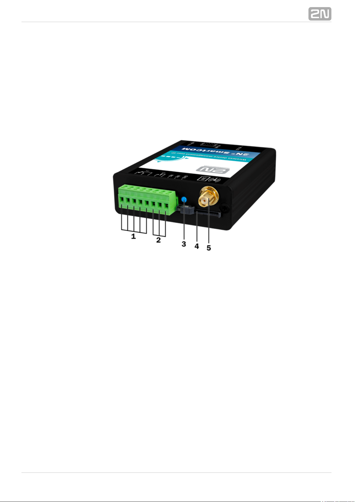
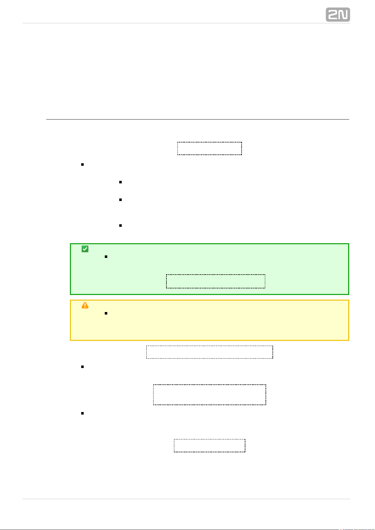
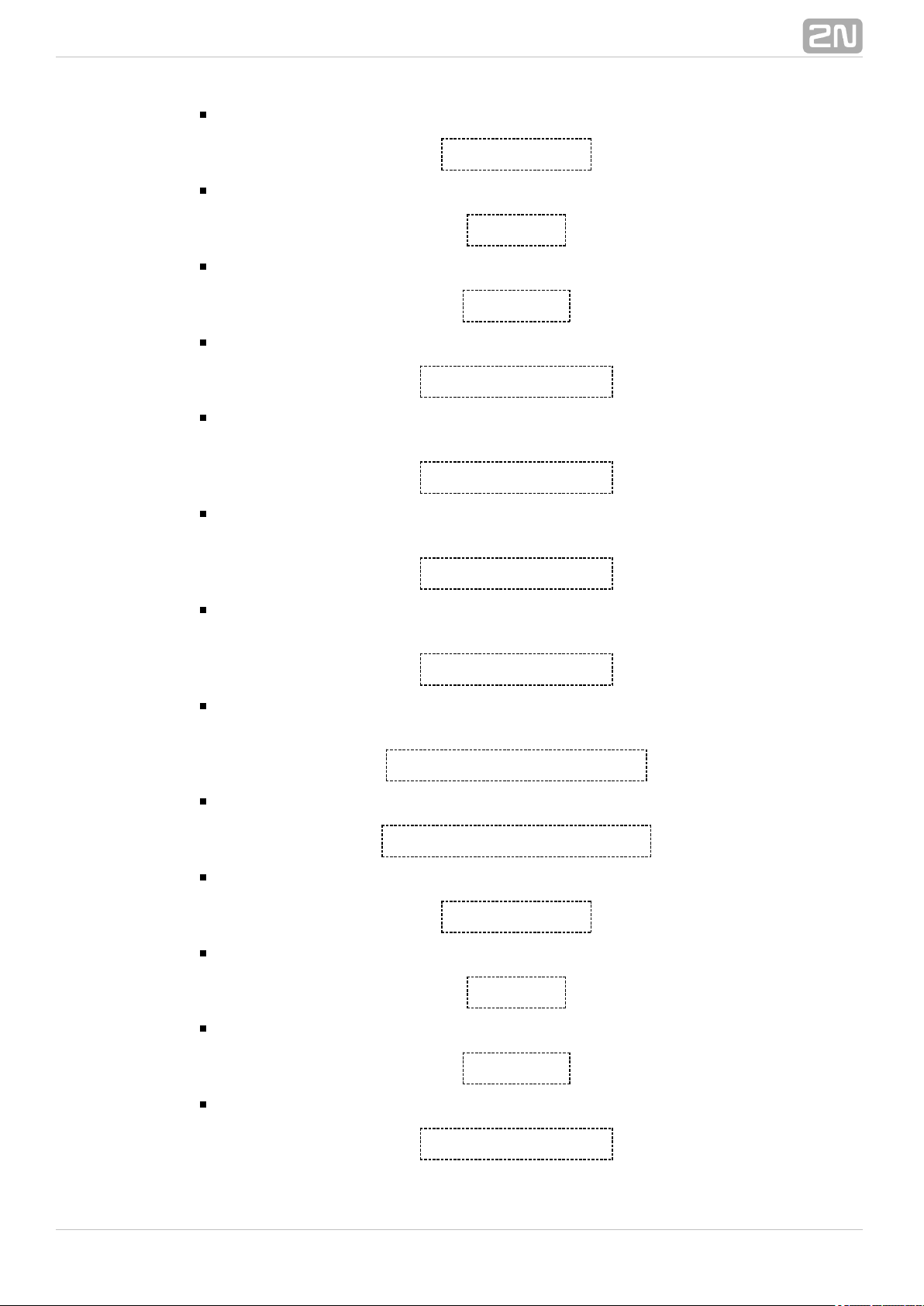
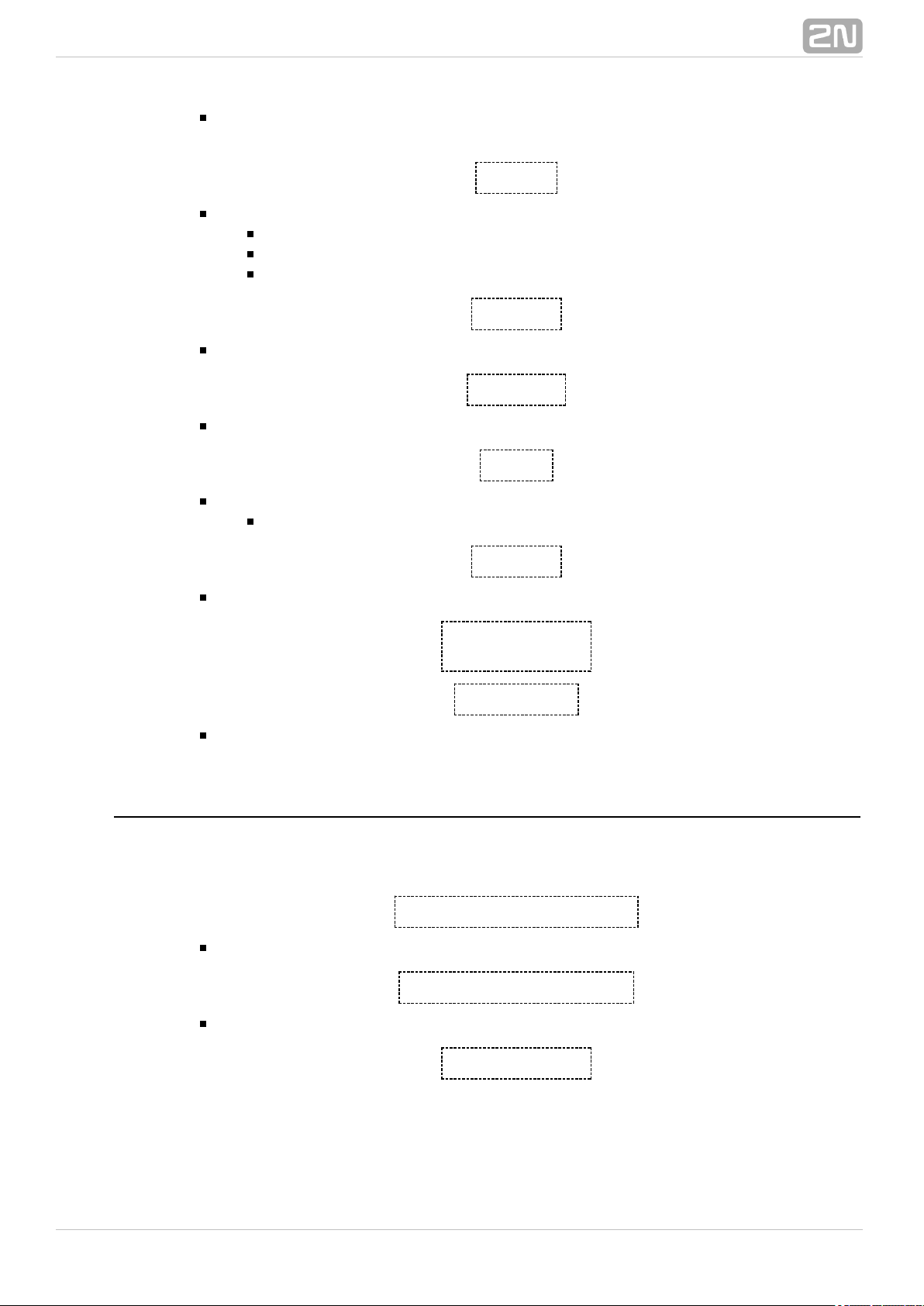
2.1 Basic Version Description
2N SmartCOM® consists of a board carrying a power supply, RS 232 and RS
485/M–Bus interfaces and a GSM module. The GSM module is responsible for a
continuous Internet connection via GPRS and two relays for output contact control.
Connectors for optional devices are located in the upper part of the u2N SmartCOM
®
nit. Refer to the figures below for description. The whole system is2N SmartCOM
®
enclosed in a solid aluminium case.
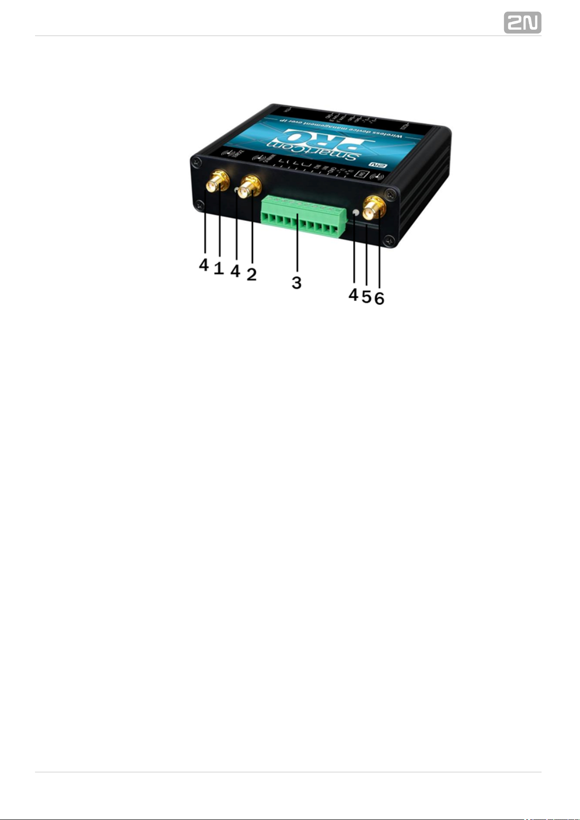
Figure: 2N SmartCOM® Description (Top View)
Relay output terminals
Input circuit terminals
GSM LED indicator
SIM holder
GSM antenna SMA connector
®
112N TELEKOMUNIKACE a.s., www.2n.cz
Page 12

1.
2.
3.
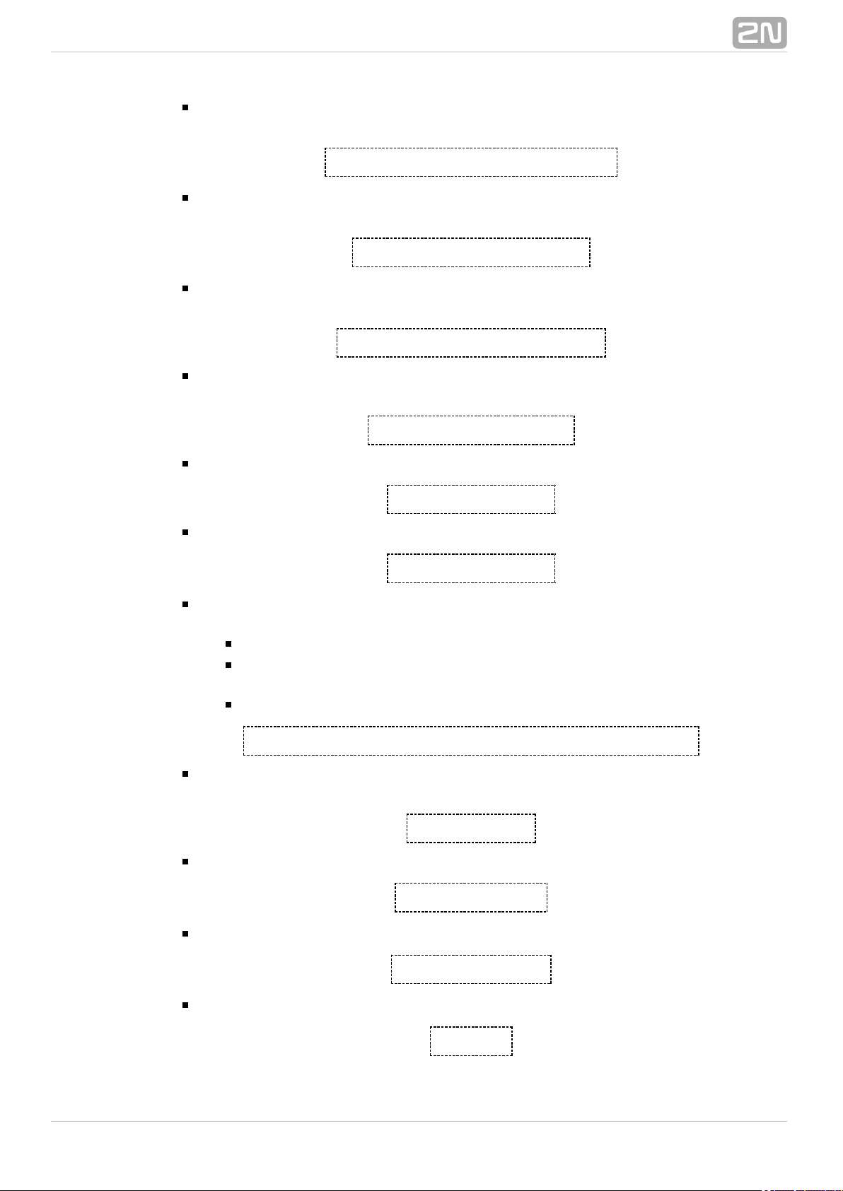
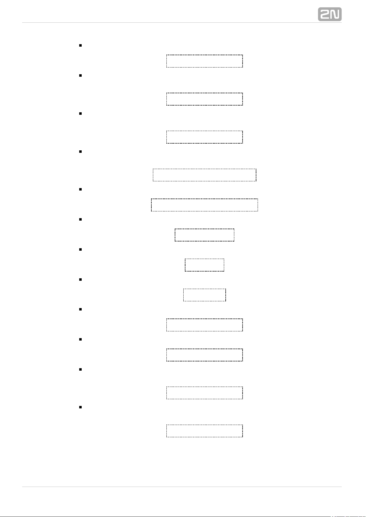
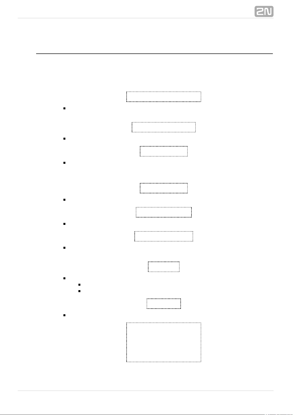
Figure: 2N SmartCOM® Connectors (Bottom View)
RS 232 bus connector
RS 485 bus connector
Power supply connector
®
122N TELEKOMUNIKACE a.s., www.2n.cz
Page 13
1.
2.
3.
4.
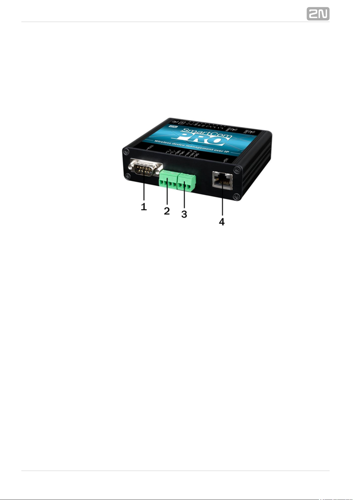
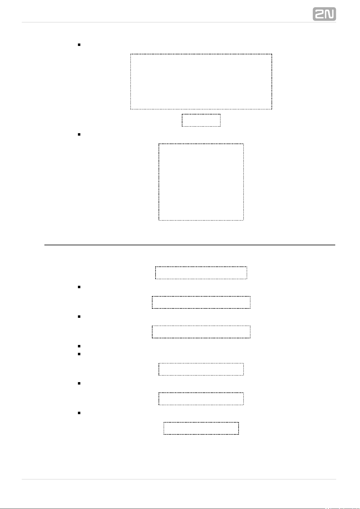
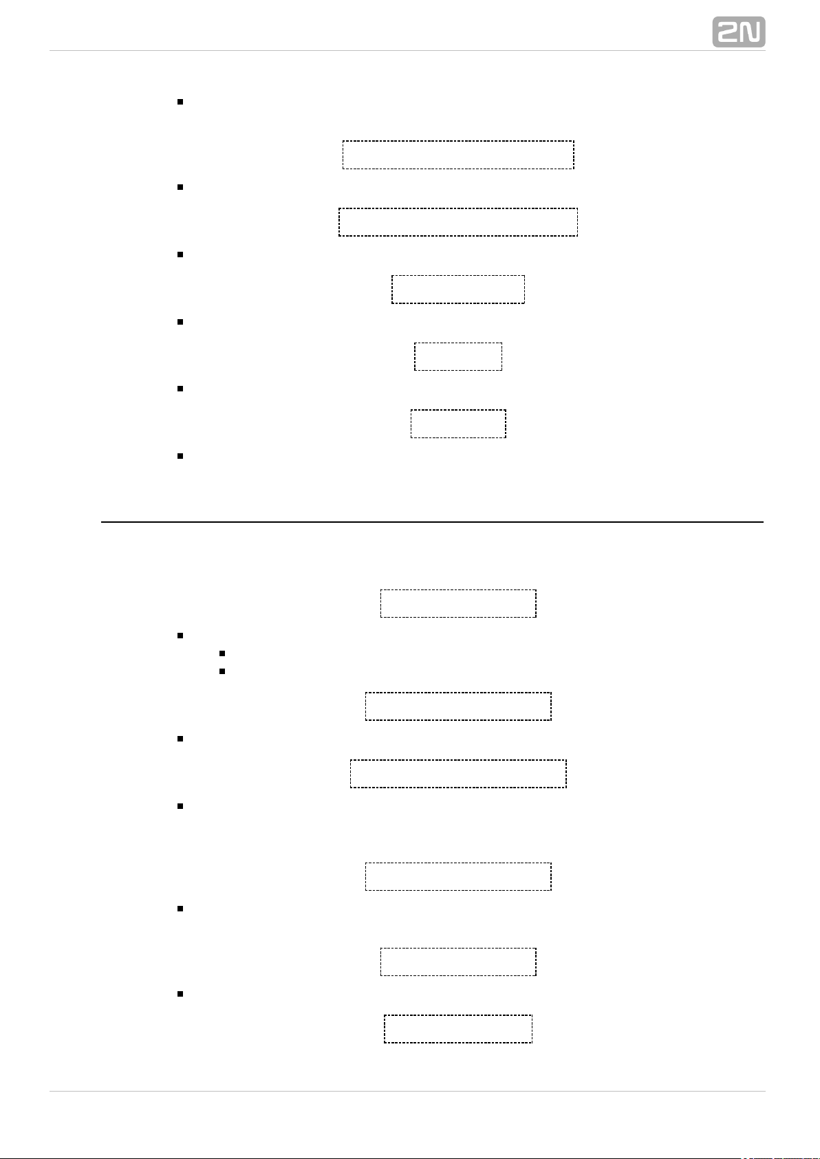
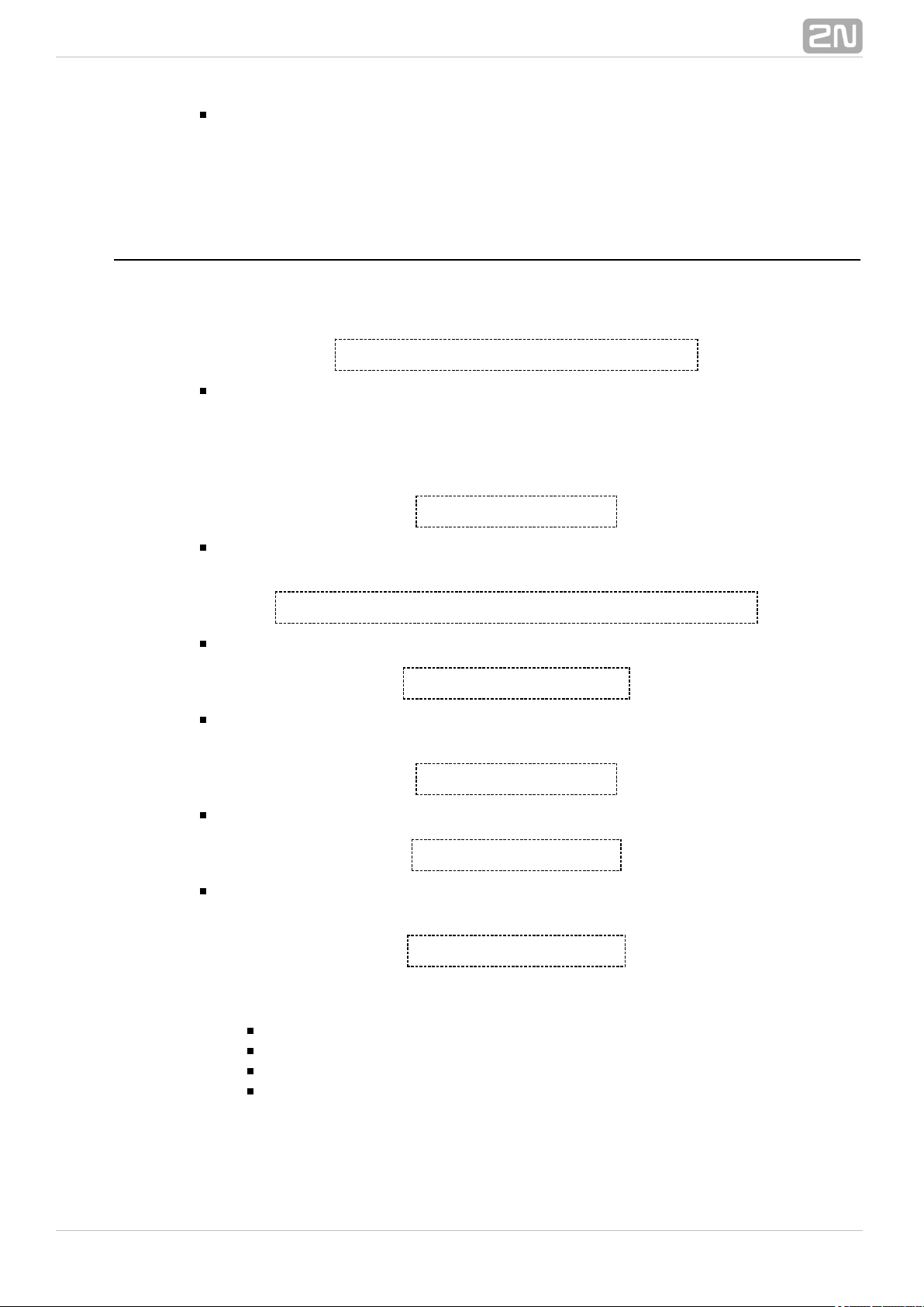
2.2 PRO Version Description
2N SmartCOM PRO® contains all basic version interfaces plus a terminal for
gel–lead–acid accumulator connection, a real time clock function, Wireless M–Bus and
ZigBee (both optional) and Ethernet interface (optional). Refer to the figures below for
description. The whole system is enclosed in a solid aluminium case.2N SmartCOM
®
Figure: 2N SmartCOM® Description (Bottom View)
RS 232 connector
Power supply and battery connector:
U +, U – – contacts for input supply voltage
in in
Batt+, Batt– – contacts for gel–lead–acid accumulator
RS 485/M–Bus/RS232 connector (depends on the device version)
Ethernet interface (optional)
®
132N TELEKOMUNIKACE a.s., www.2n.cz
Page 14
1.
2.
3.
4.
5.
6.
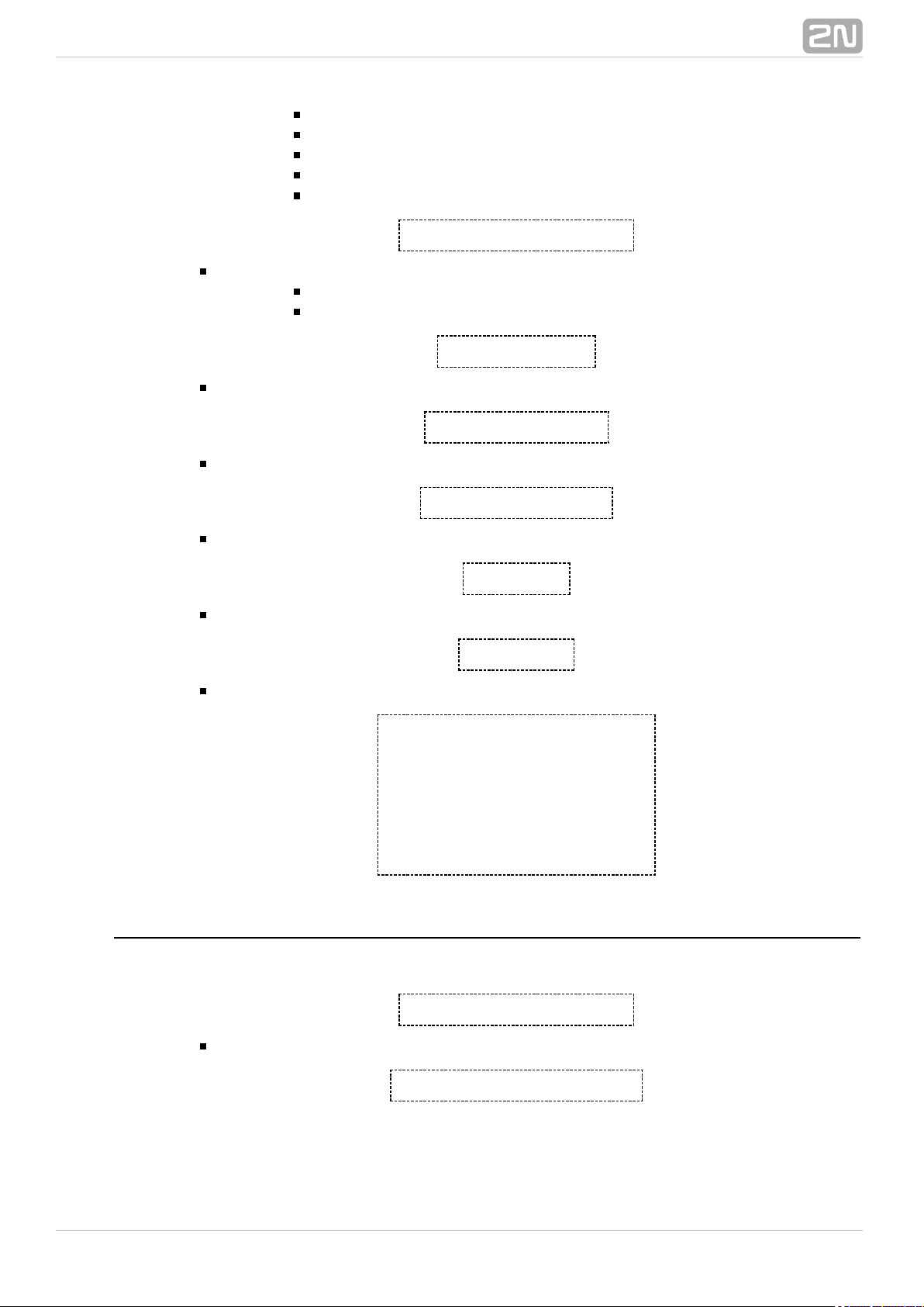
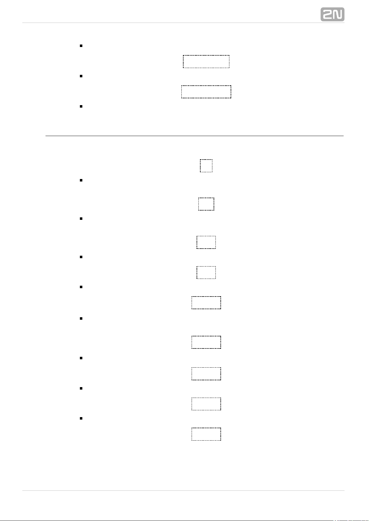
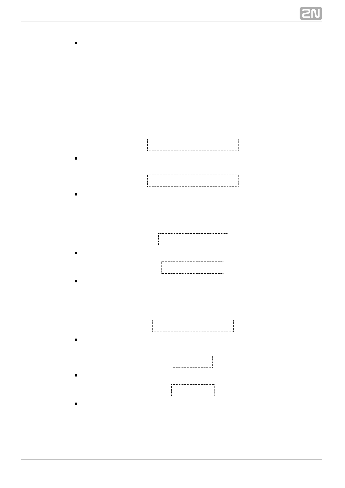
Figure: 2N SmartCOM® Connectors (Top View)
SMA connector for ZigBee antenna (optional)
SMA connector for Wireless M–Bus antenna (optional)
Input circuit terminal block:
RE1, RE2 – relay contacts
IN1, IN2 – input circuits (type is determined by jumper settings)
GND – ground to be used with input circuits IN1 and IN2
U +, U – – auxiliary contacts with supply voltage, to be used e.g. for connecting
in in
supply voltage to relays (directly connected to U +, U – contacts on 4–pin
in in
power supply connector)
Signalling LEDs (ZigBee, WMbus, GSM LED)
SIM holder
SMA connector for GSM antenna
®
142N TELEKOMUNIKACE a.s., www.2n.cz
Page 15

2.3 Before You Start
Installation Conditions
Install the GSM antenna with respect to the signal quality in the2N SmartCOM
®
location. Where the signal is poor, use a higher gain antenna (not included in the
delivery).
Install off sensitive devices and human bodies to avoid EM2N SmartCOM
®
interference.
Refer to the Technical Parameters ( ) for the allowed range of workingS. 6
temperatures.
2N SmartCOM® may not be operated on sites exposed to direct sunshine or in
the vicinity of heat sources.
2N SmartCOM® is designed for indoor use. Never expose it to rain, running
water, condensation moisture, mist, etc.
2N SmartCOM® may not be exposed to aggressive gases, acid vapours,
solvents and similar chemicals.
Caution
Make sure that you are equipped with all necessary technical means,
particularly a GPRS supporting SIM card with PIN request disable or a
PIN identical with that set in the configuration. 2N SmartCOM
®
®
152N TELEKOMUNIKACE a.s., www.2n.cz
Page 16
2.4 Mounting
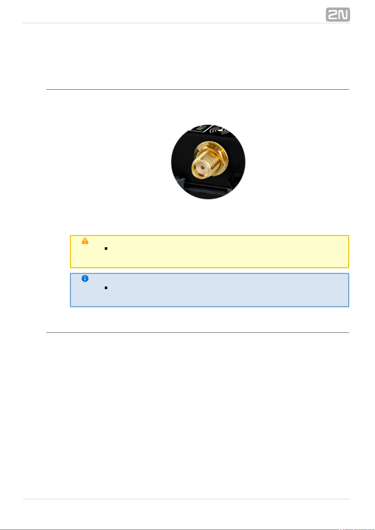
External Antenna Connection
Screw the enclosed antenna into the SMA antenna connector.
Figure: Antenna Connection
Caution
Tighten the antenna connector ; never use agently with your hand
tool!
Note
The antenna should be located in one and the same building with 2N
®
for safety reasons. SmartCOM
SIM Card Installation
Find the SIM card holder near the top.2N SmartCOM
®
®
162N TELEKOMUNIKACE a.s., www.2n.cz
Page 17

1.
2.
Figure: SIM Card Installation
Insert the SIM card in the holder.
Push the card in until it clicks into position.
Caution
Make sure that the GSM provider's SIM card is intended for the GSM
network supported by your version and that2N SmartCOM
®
GPRS–based data transmission is activated.
Make sure that the SIM card does not request the PIN or that the PIN
is identical with that set in the configuration.2N SmartCOM
®
Remember to set the relevant SIM and provider's services (call
forwarding, call barring, preferred networks, SMS centre, etc.) on your
mobile phone ( ) before inserting the SIM card in 2N MeterModem
®
2N SmartCOM.
®
Power Supply
2N SmartCOM® is DC supplied from a 12V/0.5A power adapter. Make sure that the
voltage value and polarity comply with the data specified at the powe2N SmartCOM
®
r connector before connecting your to an adapter other than that2N SmartCOM
®
included in the delivery.
is DC supplied in the range of 5–50V. Make sure that the2N SmartCOM PRO
®
voltage value and polarity comply with the data specified at the powe2N SmartCOM
®
r connector before connecting your to an adapter other than that2N SmartCOM
®
included in the delivery. Connect the supply voltage to the 4–pin connector next to the
RS232 connector. You can also connect there a gel–lead–acid accumulator as a power
supply backup. The supply voltage is also present on the 10–pin input circuit terminal
block on the opposite side of the device. These contacts can be used as auxiliary, e.g.
for connecting supply voltage to relays.
®
172N TELEKOMUNIKACE a.s., www.2n.cz
Page 18

Warning
Never connect the power supply until you have connected the
antenna to avoid the GSM module damage.
Never connect any incompliant power supply to avoid electric
accident or system damage
®
182N TELEKOMUNIKACE a.s., www.2n.cz
Page 19

3. Function and Use
In this section we provide the basic and extended functions of the pro2N SmartCOM
®
duct.
Here is what you can find in this section:
3.1 Putting in Operation
3.2 GSM LED Indicator
3.3 Input and Output Circuits
3.4 Input Calibration
®
192N TELEKOMUNIKACE a.s., www.2n.cz
Page 20
3.1 Putting in Operation
Operational state is 's main function. In this state, periodic data2N SmartCOM
®
readouts from input circuits are made. responds to queries from the2N SmartCOM
®
superior data concentrator, which can be the server, monitors the2N SmartCOM
®
events on the RS-232 / 485 / M-Bus interfaces and sends the acquired data to the
server via GPRS, or Ethernet in the case of the PRO ETH version.
Initialisation
Insert the PIN–disabled data SIM card in and connect the GSM2N SmartCOM
®
antenna and power supply as instructed in ., Mounting. Subs. 2.3
When the power supply is connected, the LED indicator on the upper2N SmartCOM
®
side of the module flashes three times quickly and then starts flashing in longer
intervals. Refer to . for LED status details. The GPRS module startsSubs. 3.2
communicating with the provider in about 10 seconds trying to log in and obtain the IP
address. The LED starts shining constantly to indicate a successful login.
Tip
2N SmartCOM® is working if the LED indicator is shining, thus
indicating a successful mobile provider connection and IP address
assignment.
To identify the IP address assigned by the mobile provider or perform 2N SmartCOM
®
the basic configuration upon power up, get connected via the serial port (RS 232). The
port is in the data mode upon power up, retransmitting all data from the input to the
GPRS network. Use the +++ sequence preceded and followed by a 1–second delay to
switch into the configuration mode. When your replies OK, start2N SmartCOM
®
configuring using the AT commands as listed below.
Restart the serial port to return to the data mode. To do so, you can either send the
ATO command or disconnect from the power supply.2N SmartCOM
®
Tip
can also be configured via Terminal Config. Refer to 2N SmartCOM
®
.S. 6
If you cannot use a PC, make the basic settings using SMS messages.
Refer to for details.S. 5
When your has been programmed as required, connect the device to2N SmartCOM
®
the available serial ports RS-232 / 485 / M-Bus. Launch the hyperterminal and get
connected to the public IP address via port 10000, which, together2N SmartCOM
®
with the serial port, can be used for configuring. Use port 10001 for retransmitting data
to RS-232 and port 10002 for retransmitting data to RS-485 / M-Bus.
®
202N TELEKOMUNIKACE a.s., www.2n.cz
Page 21

1.
2.
3.
4.
5.
3.2 GSM LED Indicator
Here the variable statuses of the server connection indicating LED are described. This
LED can have two functions: signals the terminal connection to GPRS in the
stand-alone mode and to the SC server in the TCP client mode both for 2N
®
and . SmartCOM 2N SmartCOM®PRO
For , however, set the scchled1 parameter to determine2N SmartCOM PRO ETH
®
whether the LED shall signal the GSM or ETH interface state.
Figure: Front Panel with LED Indicator
NO LIGHT – POWER OFF – indicates that the 12V power supply of the GPRS
module is disconnected or works erroneously, or the fuse is defective.
THREE QUICK FLASHES – START or RESTART – indicates the system start or
restart. This status must occur whenever the power supply is connected.
SLOW FLASHING – INITIALISATION – indicates the process of module login to
the provider and IP network.
VERY QUICK FLASHING – ERROR – indicates an error due to a wrong PIN,
missing SIM card, or fewer than three remaining PIN entering attempts.
CONSTANT SHINING – OK – logged in, IP address assigned,2N SmartCOM
®
connection successfully established. A quick flash indicates data transmission in
this status.
®
212N TELEKOMUNIKACE a.s., www.2n.cz
Page 22

3.3 Input and Output Circuits
This subsection describes the input and output circuits of including2N SmartCOM
®
main use, control and location.
Tip
2N SmartCOM® is equipped with reliable terminals for easier and
faster connection.
Input Circuits
2N SmartCOM® is equipped with two inputs, which are mutually galvanically
connected with the GND reference point (have a common GROUND). Remember to
keep the parameters specified in the Technical Parameters at the end of this manual.
The input circuits can work in three modes – voltage, current or logical levels – as
configured.
Voltage measurement
Voltage can be measured in the range between 0 and 10V DC. Make sure that the 2N
®
jumpers are set as shown in Figure 3.3 before using this mode. Use the SmartCOM
AT commands listed in (ADC) for reading and calibration.Subs. 4.2
Current measurement
Electric current can be measured in the range between 4 and 20 mA. Make sure that
the jumpers are set as shown in Figure 3.3 before using this mode. 2N SmartCOM
®
Use the AT commands listed in (ADC) for reading and calibration.Subs. 4.2
Logical level monitoring
You can monitor the logical levels of voltage and current signals. Use other commands
that those intended for classic measurements and define the threshold levels. Again,
use the AT commands for reading values on input circuits.
Pulse counting on S0 inputs
Make sure that the jumpers are set as shown in the figure below for pulse counting on
S0 inputs. The S0 input has thus a power supply of its own and can be connected
directly to the switch or relay contacts. The counter is disabled by default and has to be
enabled using the AT commands included in .Subs. 4.2
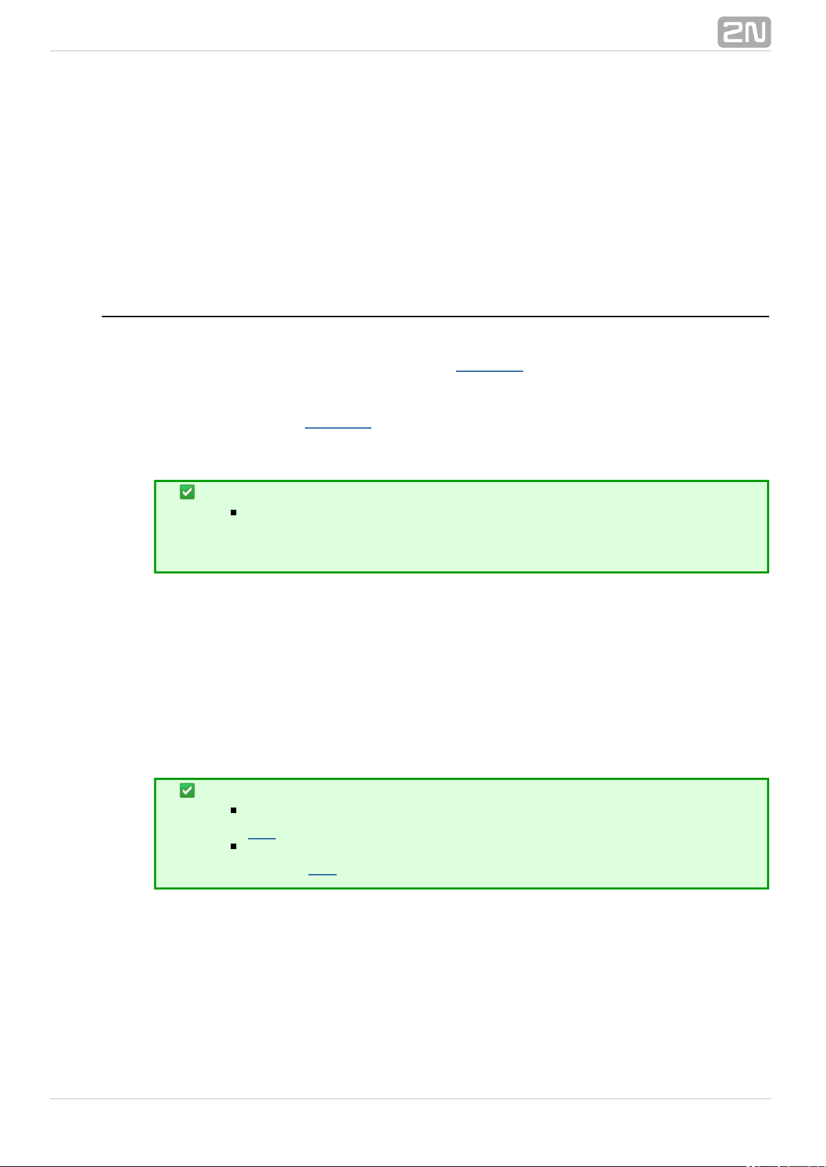
The figures below show the location of jumpers for current/voltage input switching.
Release the screws and remove the case cover to get access to the jumpers. See the
figure to the right for correct setting.
®
222N TELEKOMUNIKACE a.s., www.2n.cz
Page 23
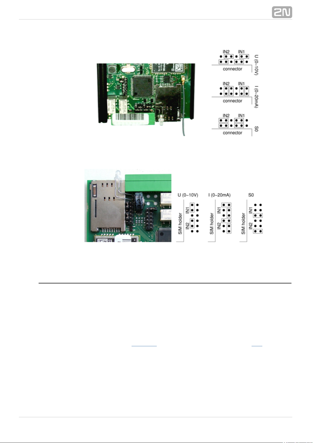
Figure: Jumper Setting–Basic Version
Figure: Jumper Setting–PRO version
Output Circuits
2N SmartCOM® is equipped with two relay outputs for turning on/off electrical
appliances (by an additional power switch, depending on their power input), or
signalling, control and so on. Remember to keep the parameters specified in the
Technical parameters at the end of this manual.
You can control the relay outputs with the AT commands from the CMD mode of the RS
232 interface, via a remote GPRS connection to the SIM card IP address, or using an
SMS message. Refer to for AT command details and for SMSSubs. 4.2 S. 5
configuration details.
®
232N TELEKOMUNIKACE a.s., www.2n.cz
Page 24
Caution
Any manual setting is valid until the next change or – Attention!
device power off. does not keep in mind the relay2N SmartCOM
®
settings and restores the default status upon power up.
Set the parameter determining the relay position upon power up to 2
to make your remember the last contact position2N SmartCOM
®
before power off. Refer to the configuration subsections for more
details.
RS-232 and RS-485 / M–Bus Interfaces
Find the interface connectors on the bottom side of . Refer to 2N SmartCOM
®
Subs.
. A 9-pin D-sub connector is used for RS-232 and a 6-pin RJ12 connector is used2.1
for RS-485 or M-Bus in the basic version. Follow the wiring2N SmartCOM
®
instructions on the label. and use a2N SmartCOM®PRO 2N SmartCOM PRO ETH
®
3-pin WAGO terminal for bus connection located on the bottom panel next to the power
supply terminals. Follow the wiring instructions on the label.
IP Access
To access via the IP protocol, use a Telnet supporting terminal and2N SmartCOM
®
get connected to the public IP address. must be in2N SmartCOM
®
2N SmartCOM
®
mode 3 , STANDALONE, to provide access to three ports, each of which serves one
interface.
Tip
Port 10000 – helps you configure, control the output relays and
measure quantities on the input circuits.
Port 10001 – works as a data pipe to port RS 232 retransmitting all
RS 232 events to GPRS.
Port 10002 – works as a data pipe to port RS 485 / M–Bus
retransmitting all RS 485 events to GPRS.
Gel–Lead–Acid Accumulator Charger
This function is available in the version only, which contains an2N SmartCOM PRO
®
intelligent charger for an external gel–lead–acid accumulator. Charging is controlled
automatically and terminated when the accumulator has been completely charged. In
the case of power failure, the system is fed continuously by the accumulator and, upon
power recovery, the accumulator is charged automatically. A 6V or 12V accumulator
can be used and charged on condition that the power voltage is 1V higher at least than
the maximum voltage of the accumulator.
®
242N TELEKOMUNIKACE a.s., www.2n.cz
Page 25

Real Time Clock
This function is available in the version only. The real time clock2N SmartCOM PRO
®
is backed up by a super capacitor, which keeps it running for 2 days in the event of
switch–off or power failure. The clock is programmed via the configuration AT interface
or from the Server automatically.2N SmartCOM
®
Wireless M–Bus Interface
This function is available in the version only, which is equipped2N SmartCOM PRO
®
with an optional Wireless M-Bus interface. The WM-Bus interface parameters depend
on the module used (radio frequency, e.g.). You can define up to 64 meters from which
the device can collect readings. Having received a WM-Bus message from a meter
defined in the meter table, saves the message into a circular2N SmartCOM PRO
®
buffer in the internal memory. The saved data can be retrieved and deleted starting
from the oldest record. When the memory fills up, the oldest data are deleted
automatically to make space to new records. You can define the minimum reading
interval for each meter. Any reading received from a meter before the end of this
interval will not be stored.
The WM-Bus module can work and support encrypted messages in four modes: T1, S1,
C1 and T1+C. In the basic configuration, the terminal does not decrypt messages and
saves them as received. If you enter the correct encryption key and enable decryption,
the received message will be decrypted and saved as a decrypted message. The
encryption keys are not stored in the terminal memory for safety reasons, but written
directly into the module. Therefore, if encryption fails, make sure that the device is
transmitting properly, check the device settings in the terminal and re-enter the
encryption key.
®
252N TELEKOMUNIKACE a.s., www.2n.cz
Page 26

ZigBee Interface
This function is available in the and 2N SmartCOM PRO
®
2N SmartCOM PRO ETH
®
versions only, which are equipped with an optional ZigBee communication module. The
ZigBee interface parameters depend on the module used (radio frequency, e.g.). You
can define up to 16 devices for mutual communication. The IEEE 802.15.4 –
ZigBee communication technology is a member of the wireless PAN group (Personal
). Another, very popular PAN member, IEEE 802.15.1 – Bluetooth, isArea Networks
widely used in consumer electronics, but is not suitable for all industrial applications.
This is why a new wireless communication standard, ZigBee, has been developed for
At present, over sixty firms including world leaders inindustrial automation.
automation are involved in ZigBee development and improvement. ZigBee has been
designed as a simple and flexible technology for extensive wireless networks where no
large data volumes are transmitted. Reliability, simple and undemanding
implementation, low power requirements and, last but not least, a good price make
ZigBee a perfect solution. Like Bluetooth, ZigBee is intended for connection of
low-power devices in PANs over distances of up to 75 metres. Being equipped with
multi-drop ad-hoc routing, ZigBee also provides communication over longer distances
without requiring direct visibility of the devices connected. It is widely used in industrial
applications and sensor networks as it needs no special licence (has a general licence).
Its working bands are approximately 868 MHz, 902–928 MHz and 2.4 GHz and
20, 40, 250 .transmisition rates amount to kbps
®
262N TELEKOMUNIKACE a.s., www.2n.cz
Page 27
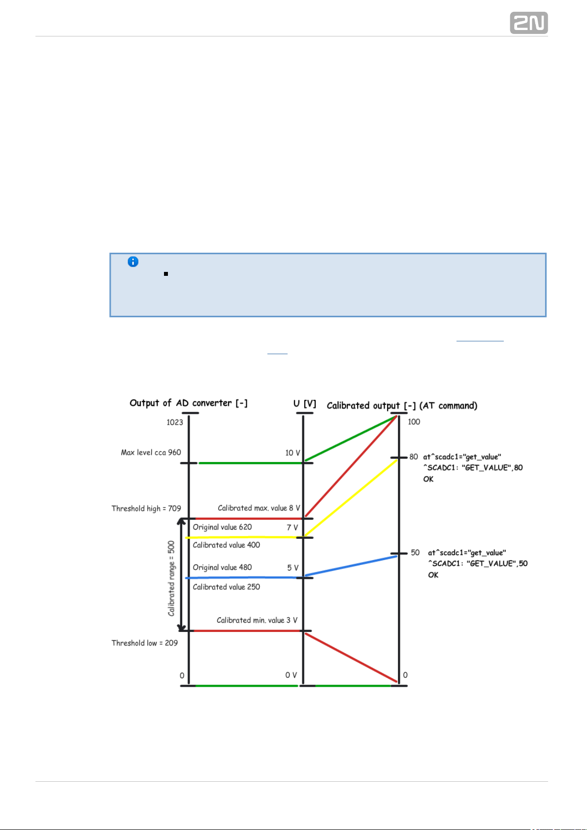
3.4 Input Calibration
A 10-bit A/D converter is connected to the IN1 and IN2 input terminals, which converts
the measured value to a number ranging between 0 and 1023. Practically, the 0 - 1020
range is used; the remaining three steps are used for overvoltage detection.
The purpose of calibration is to compensate the inaccuracy of components and external
factors and to ensure that the 960 value of the A/D converter matches exactly 10V in
each input. The value usually oscillates slightly around this point. Let us give an
example: suppose you place two terminals next to each other under identical external
conditions. One terminal will measure 966 and the other 957 for 10V. Calibrate the
input to eliminate such inconsistency.
Note
Keep in mind that an uncalibrated input is not non-functional. It is
able to measure and read values less precisely, but sufficiently for
rough voltage or current detection.
For calibration, use the terminals and AT commands described in , or theSubs. 4.2
Terminal Config tool - refer to - for setting and application details. The followingS. 6
figure shows the calibration diagram and basic principle. The meaning of the curves are
explained below.
Figure: Calibration Diagram
The green lines indicate that no calibration has been made yet. The A/D converter–
®
272N TELEKOMUNIKACE a.s., www.2n.cz
Page 28

works in the whole range and deviations may occur from the actual value measured on
the input. If you, in this situation, set Threshold low to 0V and Threshold high to 10V
on the input, the terminal will be calibrated for 10V precisely. For 0 on the input, the
AT command will return 0. For 10, we obtain 100. Thus, the calibrated input can be
considered 0 - 100% of the calibrated range.
The red lines mean that the input has been calibrated to the interval of 3 to 8V, i.e.–
to the range of 5V. This range now represents new measurement limits. If you apply
3V or less on the input, you are in the calibrated min area and the AT command will
return 0. If you apply 8V or more, you are in the calibrated max area and the AT
command will return 100. This means that the measured range width has narrowed by
50% and 0 - 100% is now mapped to the input range of 3 - 8V.
The blue line is an example of measuring in the calibrated range of 0 to 10V. Apply–
precisely one half of the calibrated voltage, i.e. 5V, to the input. The AT command will
return 50, i.e. one half of the 0 - 100 range again. In this case, 5V is the centre of the
calibrated range. If, however, the range was shifted, the value would be shifted too as
shown below.
The yellow line shows the case that 7V is applied to the input. In case you measure–
7V in the calibrated 10V range, the AT command will return 70 as 70 represents 70%
of the calibrated range. But if the range is just 3 to 8V as in the red case, 7V will
represent 80% of the calibrated range of 5V and the AT command will return 80.
If you use the calibrated input for reading logic values, keep in mind that the
calibrated area is considered unstable. Values lower than the set minimum
No value iswill be 0 and those exceeding the maximum will be 1.
guaranteed in an unstable area and a spurious state change may occur any time
in the interval. Practically, the decisive level is near the middle of the set interval.
®
282N TELEKOMUNIKACE a.s., www.2n.cz
Page 29

4. Configuration by Terminal
In this section we describe the configuration using AT commands2N SmartCOM
®
entered into the command line.
Here is what you can find in this section:
4.1 Configuration
4.2 List of Supported AT Commands
®
292N TELEKOMUNIKACE a.s., www.2n.cz
Page 30
4.1 Configuration
The basic configuration and firmware download take place during the2N SmartCOM
®
manufacturing process. In general, no additional configuration is necessary except for
GPRS connection to the Internet on the GSM module and the port baud rates, which
may be different depending on the providers and types of peripherals. You can
configure in one of the following two ways.2N SmartCOM
®
Via the RS-232 serial interface; or
Via the IP interface.
Configuration via RS 232
The RS-232 port is always in the data mode upon power up, which means that it
retransmits all captured events to GPRS port 10001. Therefore, to configure 2N
®
via the serial port, switch the port into the command mode first and then SmartCOM
get connected to it using your PC serial port. The baud rate is 115,200 bps by default.
Now enter the following sequence of characters, preceded and followed by a 1–second
delay, into the terminal:
+++
When answers OK, you can start configuring the device using the AT2N SmartCOM
®
commands listed in .Subs. 4.2
Restart the RS-232 port when you have finished configuring to return into the data
mode. Send the following command:
at^scport1="restart"
Configuration via IP
If you know the public IP address, you can configure the device2N SmartCOM
®
remotely too using the IP protocol. If not, connect to using RS-232 as2N SmartCOM
®
described above and send one of the following commands (for GPRS/Ethernet):
at^sccfg="local_ip"
at^sceth="local_ip"
2N SmartCOM® will send you the IP address as negotiated with the provider or
assigned by the DHCP server in the Ethernet case. If a fixed public IP address is
activated on the SIM card, the SIM will always use this IP address. If a dynamic public
IP address is used, check the IP address whenever your restart the device.
®
302N TELEKOMUNIKACE a.s., www.2n.cz
Page 31
Caution
Make sure that the IP address assigned to the SIM card is
public. It is because you will not be able to establish remote
connection to in the STANDALONE mode if an IP2N SmartCOM
®
address from the provider's internal range is used. The 2N
®
address need not be public if you use the TCPCLIENT SmartCOM
server connection.
If you know the public IP address, launch the Putty and get connected via port 10000,
which, together with the serial port, can also be used for configuring. Port 10000 is
used for configuration, input data reading and output control in the IP domain. It is in
the command mode upon power up and thus need neither be switched nor restarted
after configuration.
Note
This port requires the safety password if configured so.
Caution
If your fails to respond to incoming TCP connections,2N SmartCOM
®
check the status of the port to which you are connecting. If the port is
in the command mode, notification on incoming connection is sent to
the line (RING is displayed). Hence, enter the 'ata' command for
answer or set automatic answering by parameter ats0. Refer to the
subsection in the General Commands List of supported AT
below.commands
®
312N TELEKOMUNIKACE a.s., www.2n.cz
Page 32
4.2 List of Supported AT Commands
This subsection describes all the AT commands that can be used for c2N SmartCOM
®
onfiguration, including precise format and function specification.
2N SmartCOM GSM Commands
®
These commands help configure the connection to the GPRS network.
at^sccfg="mode",2
Enter the command to set the operating mode. There are three2N SmartCOM
®
options:
TCPCLIENT mode (1) - connects and retransmits2N SmartCOM
®
data from its ports to the selected server.
STANDALONE mode (3) - works as a server to2N SmartCOM
®
which clients get connected (transparent TCP – serial port
transmission).
DATA_OFF mode - GSM/UMTS module does nor log2N SmartCOM
®
in to the data network but waits for SMS.
Tip
Enter the mode number or name or select a port. The AT command
then looks as follows:
at^sccfg="mode","tcpclient"
Caution
The ETH port is visible in the network in the DATA_OFF mode. PING is
possible, but establishes no outgoing connection and rejects any
incoming connection.
at^sccfg="gprs_apn","internet.open"
Enter the command to set the APN to the mobile provider. The configuration for
O2 CZ is used as an example.
at^sccfg="gprs_user","internet"
at^sccfg="gprs_pass","hds6cd5"
These two commands help set the user name and password for authentication by
the provider. Most providers use no authentication. If your provider requires one,
ask the provider to supply the necessary data.
at^sccfg="local_ip"
®
322N TELEKOMUNIKACE a.s., www.2n.cz
Page 33
Enter the command to make return the IP addressed assigned2N SmartCOM
®
by the provider.
at^sccfg="server_ip","90.182.112.54"
Enter the command to set the IP address of the server to which 2N SmartCOM
®
should connect in mode 1.
at^sccfg="server_port","1564"
Enter the command to set the server port to which should2N SmartCOM
®
connect in mode 1.
at^sccfg="auth_pass","xJ32ppp_v1"
Enter the command to set the authorisation password for the above specified
server.
at^sccfg="sim_pin","1156"
Enter the command to set the PIN to be entered upon power up.
at^sccfg="auth_ip",1
Switch on / off access authorisation according to IP addresses.
at^sccfg="encrypt",1
Set the encryption mode for - server communication. The2N SmartCOM
®
setting options are 0–2.
Mode 0 DISABLED – encrypts no data.2N SmartCOM
®
Mode 1 OPTIONAL – encrypts data if the counterparty2N SmartCOM
®
requires so.
Mode 2 FORCED – encrypts all outgoing data.2N SmartCOM
®
at^sccfg="encrypt_key","E2978FE2978FE2978FE2978FE2978F20"
Set the encryption key using 32 valid (hexa) characters, which makes 16 ASCII,
via the ControlPanel.
at^sccfg="save"
Enter the command to save changes.
at^sccfg="restart"
Enter the command to restart .2N SmartCOM
®
at^sccfg="srestart"
Save the changes and restart 2N SmartCOM.
®
at^sccfg?
®
332N TELEKOMUNIKACE a.s., www.2n.cz
Page 34
This command displays the currently set interface values.
^SCCFG: "MODE",1
^SCCFG: "GPRS_APN","publicip.t-mobile.cz"
^SCCFG: "GPRS_USER","internet"
^SCCFG: "GPRS_PASS","hfsdj515d"
^SCCFG: "LOCAL_IP","89.24.3.195"
^SCCFG: "SIM_PIN","1234"
^SCCFG: "AUTH_IP",0
at^sccfg=?
This command displays the port value setting options.
^SCCFG: "MODE",1-3
^SCCFG: "GPRS_APN","32"
^SCCFG: "GPRS_USER","32"
^SCCFG: "GPRS_PASS","32"
^SCCFG: "LOCAL_IP"
^SCCFG: "SIM_PIN","16"
^SCCFG: "AUTH_IP,0-1
^SCCFG: "SAVE"
^SCCFG: "RESTART"
^SCCFG: "SRESTART"
Port 1 (RS 232) SC Commands
These commands are used for setting the RS 232 parameters.
at^scport1="baudrate",9600
Enter the command to set the baud rate to 9,600 bps.
at^scport1="baudrate",115200
Enter the command to set the baud rate to 115,200 bps.
at^scport1="baudrate",230400
Enter the command to set the baud rate to 230 400bps.
The baud rate can be set to 110 – 230,400 in standard steps.
at^scport1="data_bits",8
Enter the command to set the data bits to 8. Setting options: 5-8.
at^scport1="stop_bits",2
Enter the command to set the stop bits to 2. Setting options: 1-2.
at^scport1="parity",2
Enter the command to set the parity check type. Setting options: 0-4.
®
342N TELEKOMUNIKACE a.s., www.2n.cz
Page 35
0 – none
1 – even
2 – odd
3 – constant 1
4 - constant 0
at^scport1="flowcontrol",1
Enter the command to set the flow control type. Setting options 0-1.
0 - no flow control
1 - hardware flow control
at^scport1="save"
Enter the command to save the changes.
at^scport1="restart"
Enter the command to restart the port.
at^scport1="srestart"
Enter the command to save the changes and restart the interface.
at^scport1?
Enter the command to display the currently set port values.
at^scport1=?
Enter the command to display the port setting options.
^SCPORT1: "BAUDRATE",110-230400
^SCPORT1: "DATA_BITS",5-8
^SCPORT1: "STOP_BITS",1-2
^SCPORT1: "PARITY",0-4
^SCPORT1: "FLOWCONTROL",0-1
^SCPORT1: "SAVE"
^SCPORT1: "RESTART"
^SCPORT1: "SRESTART"
Port 2 (RS 485/M-Bus) SC Commands
These commands are used for setting the RS 485/M-Bus parameters.
at^scport2="baudrate",9600
Enter the command to set the baud rate to 9,600 bps.
at^scport2="baudrate",115200
®
352N TELEKOMUNIKACE a.s., www.2n.cz
Page 36

Enter the command to set the baud rate to 115,200 bps.
at^scport2="baudrate",230400
Enter the command to set the baud rate to 230,400 bps.
The baud rate can be set to 110 – 230,400 in standard steps.
at^scport2="data_bits",8
Enter the command to set the data bits to 8. Setting options: 5-8.
at^scport2="stop_bits",2
Enter the command to set the stop bits to 2. Setting options: 1-2.
at^scport2="parity",2
Enter the command to set the parity check type. Setting options: 0-4.
at^scport2="save"
Enter the command to save the changes.
at^scport2="restart"
Enter the command to restart the port.
at^scport2="srestart"
Enter the command to save the changes and restart the interface.
at^scport2?
Enter the command to display the currently set port values.
^SCPORT2: "BAUDRATE",9600
^SCPORT2: "DATA_BITS",8
^SCPORT2: "STOP_BITS",1
^SCPORT2: "PARITY",0
at^scport2=?
Enter the command to display the port setting options.
Relay Outputs
These commands are used for relay output control.
at^screl1?
Enter the command to identify the status of relay 1.
at^screl1=0
®
362N TELEKOMUNIKACE a.s., www.2n.cz
Page 37

Enter the command to open relay 1.
at^screl1=0,0
Enter the command to open relay 1. The relay will be open after the terminal
restart.
at^screl1=0,1
Enter the command to open relay 1. The relay will be closed after the terminal
restart.
at^screl1=0,2
Enter the command to open relay 1. The relay will be in the position as before
restart after the terminal restart.
at^screl1=1
Enter the command to close relay 1.
at^screl1=1,0
Enter the command to close relay 1. The relay will be open after the terminal
restart.
at^screl1=1,1
Enter the command to close relay 1. The relay will be closed after the terminal
restart.
at^screl1=1,2
Enter the command to close relay 1. The relay will be in the position as before
restart after the terminal restart.
at^screl2?
Enter the command to identify the status of relay 2.
at^screl2=0
Enter the command to change the status of relay 2.
at^screl2=0,0
Enter the command to change the status of relay 2. The relay will be in this
position after restart.
at^screl2=0,1
Enter the command to change the status of relay 2. The relay will be in the
opposite position after restart.
at^screl2=0,2
®
372N TELEKOMUNIKACE a.s., www.2n.cz
Page 38

Enter the command to change the status of relay 2. The relay will be in the
position as before restart after the terminal restart.
at^screl2=1
Enter the command to change the status of relay 2.
at^screl2=1,0
Enter the command to change the status of relay 2. The relay will be in the
opposite position after restart.
at^screl2=1,1
Enter the command to change the status of relay 2. The relay will be in this
position after restart.
at^screl2=1,2
Enter the command to change the status of relay 2. The relay will be in the
position as before restart after the terminal restart.
ADC – Input Circuits
These commands help control the input circuits, set calibration and make
measurements.
at^scadc1="get_value"
Enter the command to measure the value of the selected port and send the
measured value.
at^scadc1="adc_value"
Enter the command to make the measurement and return the A/D converter
value.
at^scadc1="calib_min"
Enter the command to make automatic port calibration according to the currently
measured value.
at^scadc1="calib_max"
Enter the command to make automatic port calibration according to the currently
measured value.
at^scadc1="threshold_low",200
Manual calibration setting (minimum values). Setting options: 0 – 960.
at^scadc1="threshold_high",250
®
382N TELEKOMUNIKACE a.s., www.2n.cz
Page 39
Manual calibration setting (maximum values). Setting options: 0 – 960.
at^scadc1="save"
Enter the command to save the changes.
at^scadc1?
Enter the command to display the currently set port values.
at^scadc1=?
Enter the command to display the port setting options.
at^scadc2="get_value"
Enter the command to measure the value of the selected port and send the
measured value.
at^scadc2="adc_value"
Enter the command to make the measurement and return the A/D converter
value.
at^scadc2="calib_min"
Enter the command to make automatic port calibration according to the currently
measured value.
at^scadc2="calib_max"
Enter the command to make automatic port calibration according to the currently
measured value.
at^scadc2="threshold_low",300
Manual calibration setting (minimum values). Setting options: 0 – 960.
at^scadc2="threshold_high",350
Manual calibration setting (maximum values). Setting options: 0 – 960.
at^scadc2="save"
Enter the command to save the changes.
at^scadc2?
Enter the command to display the currently set port values.
at^scadc2=?
Enter the command to display the port setting options.
at^scdin1="get_value"
®
392N TELEKOMUNIKACE a.s., www.2n.cz
Page 40
Enter the command to detect the logical level on the port and send value 1/0.
at^scdin1="adc_value"
Enter the command to make the measurement and return the A/D converter
value.
at^scdin1="calib_min"
Enter the command to make automatic port calibration according to the currently
measured value.
at^scdin1="calib_max"
Enter the command to make automatic port calibration according to the currently
measured value.
at^scdin1="threshold_low",400
Manual calibration setting (minimum values). Setting options: 0 – 960.
at^scdin1="threshold_high",450
Manual calibration setting (maximum values). Setting options: 0 – 960.
at^scdin1="save"
Enter the command to save the changes.
at^scdin1?
Enter the command to display the currently set port values.
at^scdin1=?
Enter the command to display the port setting options.
at^scdin2="get_value"
Enter the command to detect the logical level on the port and send value 1/0.
at^scdin2="adc_value"
Enter the command to make the measurement and return the A/D converter
value.
at^scdin2="calib_min"
Enter the command to make automatic port calibration according to the currently
measured value.
at^scdin2="calib_max"
®
402N TELEKOMUNIKACE a.s., www.2n.cz
Page 41
Enter the command to make automatic port calibration according to the currently
measured value.
at^scdin2="threshold_low",500
Manual calibration setting (minimum values). Setting options: 0 – 960.
at^scdin2="threshold_high",550
Manual calibration setting (maximum values). Setting options: 0 – 960.
at^scdin2="save"
Enter the command to save the changes.
at^scdin2?
Enter the command to display the currently set port values.
at^scdin2=?
Enter the command to display the port setting options.
S0 – Pulse Counting
The commands below are used for pulse counter state setting and reading out on S0
inputs.
at^scpulse1="state"
Enter the command to know the current states of the input 1 counter.
COUNTING- counting in progress
STOPPED- counting stopped
at^scpulse1="get_value"
Enter the command to read out the counter state.
at^scpulse1="set_value",100
Enter the command to set the count of counter pulses in case you do not want to
start from 0. In this case, 100 will be set. The available range is 0 –
4294967295.
at^scpulse1="stimer",60
Enter the command to define the intervals in seconds for storing the counter
value in the EEPROM. The available range is 5 – 10000s.
at^scpulse1="start"
Enter the command to enable pulse counting on input 1.
at^scpulse1="stop"
®
412N TELEKOMUNIKACE a.s., www.2n.cz
Page 42

Enter the command to disable pulse counting on input 1.
at^scpulse1="clear"
Enter the command to clear the input 1 counter.
at^scpulse1="save"
Enter the command to store the counter value in the EEPROM manually.
at^scpulse1?
Enter the command to display the current interface settings.
at^scpulse1=?
Enter the command to display the setting options for the interface.
at^scpulse2="state"
Enter the comma1nd to know the current states of the input 2 counter.
COUNTING- counting in progress
STOPPED- counting stopped
at^scpulse2="get_value"
Enter the command to read out the counter state.
at^scpulse2="set_value",100
Enter the command to set the count of counter pulses in case you do not want to
start from 0. In this case, 100 will be set. The available range is 0 –
4294967295.
at^scpulse2="stimer",60
Enter the command to define the intervals in seconds for storing the counter
value in the EEPROM. The available range is 5 – 10000s.
at^scpulse2="start"
Enter the command to enable pulse counting on input 2.
at^scpulse2="stop"
Enter the command to disable pulse counting on input 2.
at^scpulse2="clear"
Enter the command to clear the input 2 counter.
at^scpulse2="save"
®
422N TELEKOMUNIKACE a.s., www.2n.cz
Page 43
Enter the command to store the counter value in the EEPROM manually.
at^scpulse2?
Enter the command to display the current interface settings.
at^scpulse2=?
Enter the command to display the setting options for the interface.
General Commands
General commands for .2N SmartCOM
®
at
A terminal function control command, which executes no action and always gets
the OK answer.
ate
Enter the command to disable echo (replies are displayed only instead of
commands).
ate0
Enter the command to disable echo.
ate1
Enter the command to enable echo.
at+cgmi
Enter the command to display the manufacturer – 2N SmartCOM
®
2N
®
Telekomunikace a.s.
at+cgmm
Enter the command to display the model - .2N SmartCOM
®
at+cgmr
Enter the command to display the current firmware version - SC_vxx.xx.
at+cgsn
Enter the command to display the GSM module IMEI.
at+cimi
®
432N TELEKOMUNIKACE a.s., www.2n.cz
Page 44

Enter the command to display the SIM card IMSI.
at+gmi
Enter the command to display the manufacturer – 2N SmartCOM
®
2N
®
Telekomunikace a.s.
at+gmm
Enter the command to display the model - .2N SmartCOM
®
at+gmr
Enter the command to display the current firmware version - SC_vxx.xx.
at+gsn
Enter the command to display the GSM module IMEI.
ati
Enter the command to display the model - .2N SmartCOM
®
ati3
Enter the command to display the current firmware version - SC_vxx.xx.
ati4
Enter the command to display the serial number.2N SmartCOM
®
ato
Enter the command to switch the port from the command mode to the
transparent mode.
ata
Enter the command to switch the port from the command mode to the
transparent mode during an incoming TCP connection ringing.
ath
Enter the command to terminate (reject) an incoming TCP connection ringing.
ats0?
Enter the command to display the automatic answering of incoming calls.
0 - means that incoming calls will be ignored and should be answered
manually using the ata command.
Digit – count of rings after which the incoming call is answered
automatically.
ats0=5
®
442N TELEKOMUNIKACE a.s., www.2n.cz
Page 45

Enter the command to set the count of rings before automatic answering to 5.
The port is automatically switched into the transparent modes after an incoming
RING.
at^sc232at=1
Enter the command to set the AT mode upon power up.
0 - disabled. The port will be in the DATA mode upon power up.
1 - enabled. The port will be in the CMD mode upon power up.
at^sc232at?
Enter the command to display the automatic AT mode setting state.
at^sc232at=?
Enter the command to to display the automatic AT mode setting options.
at^sccfgall?
Enter the command to display the currently set values for all interfaces.
^SCCFG: "MODE","TCPCLIENT"
^SCCFG: "GPRS_APN","internet.t-mobile.cz"
^SCCFG: "GPRS_USER","internet"
^SCCFG: "GPRS_PASS","internet"
^SCCFG: "LOCAL_IP","85.44.9.234"
^SCCFG: "SERVER_IP","90.182.12.134"
^SCCFG: "SERVER_PORT",1620
^SCCFG: "AUTH_PASS","hjwej549f"
^SCCFG: "SIM_PIN","2494"
^SCCFG: "AUTH_IP",0
^SCPORT1: "BAUDRATE",115200
^SCPORT1: "DATA_BITS",8
^SCPORT1: "STOP_BITS",1
^SCPORT1: "PARITY",0
^SCPORT1: "FLOWCONTROL",0
^SCPORT2: "BAUDRATE",115200
^SCPORT2: "DATA_BITS",8
^SCPORT2: "STOP_BITS",1
^SCPORT2: "PARITY",0
Access Authorisation According to IP Addresses
These commands are used for setting 5 IP addresses authorised for access to this
terminal. Connections coming from other IP addresses will be ignored.
at^sccfg="auth_ip",1
Switch on / off access authorisation according to IP addresses.
at^scipauth="add","54.182.153.21"
®
452N TELEKOMUNIKACE a.s., www.2n.cz
Page 46

Enter the command to add an IP address to the list end. When the maximum
count of addresses in the list is reached, the command will be rejected.
at^scipauth="remove",1-5
Enter the command to remove an IP address from the list. Select the position
using parameters 1 to 5.
at^scipauth="clear"
Enter the command to delete all IP addresses from the list.
at^scipauth?
Enter the command to write out the list of set IP addresses.
SCIPAUTH: 1> "90.182.112.54"
SCIPAUTH: 2> "90.182.112.5"
at^scipauth=?
Enter the command to display the setting options for the interface.
SCIPAUTH: "ADD","15"
SCIPAUTH: "REMOVE",1-5
SCIPAUTH: "CLEAR"
Test Command
This command is used for terminal testing. Enter this command to monitor the terminal
state for provider's or Server connection troubleshooting purposes,2N SmartCOM
®
for example.
at^sctest
Enter the command to test the basic functions of the terminal: GSM module login
to the provider's network, GPRS data connection operability and 2N SmartCOM
®
Server connection, for example. You will get the following reply, for example:
at^sctest
OK
Entering the test mode
GSM state: GPRS running
-testing GSM module: running
-testing MUX running: OK
-testing MUX command: OK
-testing SIM presence: OK
-checking SIM state: SIM ready
-checking GSM registration: local network
-testing signal strength: -65dBm (STRONG)
-reading operator name: "T-Mobile CZ"
-reading local address: "10.168.174.3"
SmartCOM mode: "TCPCLIENT"
®
462N TELEKOMUNIKACE a.s., www.2n.cz
Page 47

SmartCOM state: Client authenticated
Leaving the test mode
OK
Caution
When you have sent the command to , the data2N SmartCOM
®
channel serving the peer on TCP port 10002 will be closed. It is
because this channel is used for GSM module communication during
command execution. When the command has been executed, the
original channel setup is restored and a new incoming connection is
awaited.
Other Commands – Boot, State, Service, Others
These commands are used for firmware upgrade and servicing of the GSM module.
at^scupg="http://star.2n.cz/~fejfar/SmartCOM_SC_v00-04.bin"
The command is used for firmware upgrade. It includes the address of the server
where it is located and the version to be downloaded.
at^screstart
The command is used for terminal restart.
at^scfres
This command makes the factory reset of the unit connected.2N SmartCOM
®
at^sc232lock=0–1
Enter the command to enable RS-232 authentication, i.e. password authorisation
for connection. 0 = disabled, 1 = enabled.
at^sc232lock?
Enter the command to display the current RS-232 lock setting state.
at^sc232lock=?
Enter the command to display the RS-232 lock setting options.
at+csq
Enter the command to display the signal intensity.
+CSQ: 99,99
at^scop?
®
472N TELEKOMUNIKACE a.s., www.2n.cz
Page 48
Enter the command to display the GSM provider to which is2N SmartCOM
®
currently logged in.
at^scms?
This command specifies the GSM module.
WISMO228
WAVECOM MODEM
L23_00gg.WISMO228 140711
at^iccid?
Enter the command to display the SIM ICCI (Integrated Circuit Card IDentifier).
at^scpras?
Enter the command to display the remaining PIN entering attempts.
at^sig?
Enter the command to display signal intensity in dBm.
^SIG: -65dBm (STRONG)
at^scerr?
Enter the command to write out the error buffer status.
^SCERR: 72> 8,10
^SCERR: 73> 8,10
at^scerrclear
Enter the command to delete the error buffer contents.
Charger (for 2N SmartCOM PRO Only)
®
These commands are implemented in the charger-containing ve2N SmartCOM PRO
®
rsion only.
at^scchg="max_voltage",6800
Enter the command to set the maximum accumulator voltage in mV.
at^scchg="max_current",350
Enter the command to set maximum charging current in mA.
at^scchg="state"
®
482N TELEKOMUNIKACE a.s., www.2n.cz
Page 49

Enter the command to know the current charging state.
ACTIVE- charging activated.
STOPPED- charging stopped.
at^scchg="start"
Enter the command to enable the charging function.
at^scchg="stop"
Enter the command to disable the charging function.
at^scchg="save"
Enter the command to save the currently made changes.
at^scchg="srestart"
Enter the command to save the changes and modify the charging parameters
immediately.
at^scchg?
Enter the command to display the current charger settings and charging state.
at^scchg=?
Enter the command to display the charger setting options.
Warning
Remember to set the charger parameters before connecting the
accumulator and starting the charging process. Make sure that the
settings are in compliance with the accumulator manufacturer's
catalogue values to avoid accumulator damage, fire or explosion.
Caution
Use a 6V or 12V gel-lead-acid accumulator only for charging. Make
sure that the charging voltage is at least 1V higher than the maximum
voltage of the accumulator connected.
Real Time Clock (for 2N SmartCOM PRO Only)
®
These commands are implemented in the real time clock containing 2N SmartCOM
®
version only.PRO
at^scclk="RR/MM/DD,hh:mm:ss+ZZzz"
Enter the command to set the real time clock. The ZZzz parameter means a time
zone, denoting ZZ hours and zz minutes shift against the GMT.
at^scclk?
®
492N TELEKOMUNIKACE a.s., www.2n.cz
Page 50
Enter the command to display the current time in the following format:
^SCCLK: "12/04/19,16:00:25+0200"
(April 19, 2012, 16:00:25, time zone: 2 hours from GMT)
Wireless M-Bus (for 2N SmartCOM PRO Only)
®
These commands are implemented in the version only, which2N SmartCOM PRO
®
contains an optional Wireless M-Bus module.
at^scwmbus="dev_add","MAN",12345678<,600>
Enter the command to add an item to a table of meters to be read. 'MAN' is a
three-character abbreviation for the manufacturer, followed by the meter serial
number. The last parameter denotes the minimum time interval in seconds
between two stored readings of the meter to be added. If the last parameter is
not entered, all messages received from the meter are stored.
at^scwmbus="decrypt",1
Enter the command to enable decryption of messages captured on the module.
Setting options: 0 - 1.
at^scwmbus="key_add",1,A5B95C144134DE257AF2ED4F384C7EB7
Enter the command to set the encryption key for meter 1.
at^scwmbus="dev_remove",1
Enter the command to remove an item from the meter table; the parameter sets
the meter position in the table.
at^scwmbus="dev_clear"
Enter the command to clear the whole meter table.
at^scwmbus="get_oldest"
Enter the command to write out the oldest record from the Wireless M-Bus meter
data space. Example of a reply:
^SCDATA: "WMBUS",,,,,""
Meaning of parameters:
timestamp – record receiving time (UNIX timestamp)
id – record code in circular buffer
rssi – signal strength in dBM during message receiving
len – received message length in bytes
®
502N TELEKOMUNIKACE a.s., www.2n.cz
Page 51

Tip
You can find different message formats is earlier FW versions:
^SCWMBUS: <timestamp>,<id>,<rssi>,<len>,"<binary data in
hexadecimal format>"
There is a difference in data contents in this message: three
information bytes on the Radiocrafts module are added to the end.
at^scwmbus="get_oldest"<,n>
Enter the command to enable mass read-out of the messages. The optional n
parameter defines how many messages are to be read out.
at^scwmbus="del_oldest"
Enter the command to delete the oldest record from the Wireless M-Bus meter
data space. Delete the oldest record and enter the 'get_oldest' command to read
the oldest but one record.
at^scwmbus="del_oldest"<,n>
Enter the command to enable mass deletion of the messages. The optional n
parameter defines how many messages are to be deleted.
at^scwmbus="del_all"
Enter the command to delete all records from the Wireless M-Bus meter data
space.
at^scwmbus="mode",11
Enter the command to set the device operating mode.
1 - T1
3- S1
8- C1
11- T1+C
17 - N1
Note
The 17 - N1 mode is available only if the terminal is equipped with a
WMbus module, which supports the mode.
at^scwmbus="get_space"
Enter the command to display free memory space for WM-bus message storing.
at^scwmbus="mess_cnt"
Enter the command to display the count of WM-bus messages received.
at^scwmbus="RF_channel",1
®
512N TELEKOMUNIKACE a.s., www.2n.cz
Page 52
1.
2.
3.
4.
5.
6.
7.
8.
9.
10.
Enter the command to define the WMbus transmission channel. Setting options:
1 - 10.
169.406250 MHz (Channel 1a)
169.418750 MHz (Channel 1b)
169.431250 MHz (Channel 2a)
169.443750 MHz (Channel 2b)
169.256250 MHz (Channel 3a)
169.458750 MHz (Channel 3b)
169.437500 MHz (Channel g)
169.412500 MHz (Channel 1)
169.437500 MHz (Channel 2)
169.462500 MHz (Channel 3)
at^scwmbus="preamble_len",0
Enter the command to define the frame format. 0 means 4 (short) / Frame
format A. 1 - 70 (long) / Frame format A.
at^scwmbus="Install_mode",0
Enter the command to switch the normal and filter off options. In the normal
mode, data are received from the defined modules only and the other modules
are ignored. In the filter off mode, the module receives and saves all data from
all modules.
Setting options: 0 - normal, 1 - filter off.
at^scwmbus="restart"
Enter the command to restart the WMbus module.
at^scwmbus="sniff"
Enter the command to enable the 'sniff' mode to make the WMbus module
capture and display all messages from the devices in the vicinity. After the
command is entered, the connect message gets displayed and the terminal starts
writing out the messages. Press Enter to quit. The disconnect message will be
displayed for confirmation.
at^scwmbus="module_type"
Enter the command to display information on the WMbus module. Response
example: ^SCWMBUS: "MODULE_TYPE","RC1180-MBUS3,2.00,3.14"
at^scwmbus?
Enter the command to display the currently set Ethernet parameters.
at^scwmbus=?
Enter the command to display the Wireless M-Bus setting options.
®
522N TELEKOMUNIKACE a.s., www.2n.cz
Page 53

Ethernet (for 2N SmartCOM PRO ETH Only)
®
These commands are implemented in the Ethernet containing E2N SmartCOM PRO
®
TH version only.
at^sceth="ip_method","DHCP"
Enter the command to set the method of IP address setting:
DHCP – automatic IP address setting from DHCP server.
FIXED – manual IP address setting.
at^sceth="local_ip"
Enter the command to return the current IP address used on the Ethernet port.
at^sceth="fixed_ip","192.168.1.1"
Manual IP address setting.
at^sceth="mask","255.255.255.0"
Manual network mask setting.
at^sceth="gateway","192.168.1.254"
Manual default gateway setting.
at^sceth="dns1","0.0.0.0"
Manual primary DNS setting.
at^sceth="dns2","0.0.0.0"
Manual secondary DNS setting.
at^sceth="save"
Enter the command to save changes.
at^sceth="restart"
Enter the command to restart the Ethernet port.
at^sceth="srestart"
Enter the command to save the changes and restart the Ethernet port.
at^sceth?
®
532N TELEKOMUNIKACE a.s., www.2n.cz
Page 54

Enter the command to display the currently set Ethernet parameters.
^SCETH: "IP_METHOD","FIXED"
^SCETH: "LOCAL_IP","192.168.1.1"
^SCETH: "FIXED_IP","192.168.1.1"
^SCETH: "MASK","255.255.255.0"
^SCETH: "GATEWAY","192.168.1.254"
^SCETH: "DNS1","192.168.1.1"
^SCETH: "DNS2","0.0.0.0"
at^sceth=?
Enter the command to display the Ethernet setting options.
^SCETH: "IP_METHOD","FIXED"|"DHCP"
^SCETH: "LOCAL_IP"
^SCETH: "FIXED_IP","7-15"
^SCETH: "MASK","7-15"
^SCETH: "GATEWAY","7-15"
^SCETH: "DNS1","7-15"
^SCETH: "DNS2","7-15"
^SCETH: "SAVE"
^SCETH: "RESTART"
^SCETH: "SRESTART"
at^scchprim="GSM"
Enter the command to set the primary channel to be used for creating IP
connections.
GSM – connections will be created via GPRS.
ETH – connections will be created via Ethernet.
at^scchprim?
Enter the command to display the currently set primary channel.
at^scchled1="GSM"
Enter the command to set the LED function.
GSM – LED shows the state of GPRS connection.
ETH – LED shows the state of the Ethernet interface.
at^scchled1?
Enter the command to display the currently set LED function.
®
542N TELEKOMUNIKACE a.s., www.2n.cz
Page 55
SC Ping
These commands are available in the and vers2N SmartCOM
®
2N SmartCOM®PRO
ions only. Enter the commands to set periodical pinging to the set address in defined
intervals. Use SC Ping to ensure the correct function of NFG syntax in UDF or keep
firewall connection if the terminal is in the STANDALONE mode.
at^scping="host","8.8.8.8"
Enter the command to set the Host IP address to which the ICMP request shall be
sent.
at^scping="interval",5
Enter the interval in minutes. 0 means that periodical pings are deactivated.
at^scping="test"
Enter the 'test' command to test configuration before saving. The currently
changed value is always saved and thus no restart is needed during setting and
functionality check.
at^scping="save"
Enter the command to save the changes.
at^scping="restart"
Enter the command to restart the function.
at^scping="srestart"
Enter the command to save the changes and reset the ping parameters
immediately.
at^scping?
Enter the command to display the current interface values.
SCPING: "HOST","8.8.8.8"
SCPING: "INTERVAL",0
at^scping=?
Enter the command to display the interface setting options.
SCPING: "HOST","1-32"
SCPING: "INTERVAL",0-65534
SCPING: "TEST"
SCPING: "SAVE"
SCPING: "RESTART"
SCPING: "SRESTART"
®
552N TELEKOMUNIKACE a.s., www.2n.cz
Page 56

ZigBee (for 2N SmartCOM PRO Only)
®
These commands are available in the and 2N SmartCOM PRO
®
2N SmartCOM PRO
®
versions only, which are equipped with an optional ZigBee module. You can defineETH
up to 16 devices to be saved in the database and communicated with.
at^sczb="add",<16 HEX>
Enter the command to add a device to the table. "<16 HEX>" is a 16-character
IEEE address. Contact your meter manufacturer for these parameters.
Tip
The IEEE ZigBee addresses have the following format: 00:15:
. The AT command for adding a device with thebc:00:1d:00:0e:c5
selected address is as follows:
at^sczb="add",0015bc001d000ec5
The command adds the device to the first vacant place in the table.
at^sczb="del",<dev_id>
Enter the command to remove a device from the table. Setting options: 1 - 16.
at^sczb="onoff_get",<dev_id>
Enter the command to write out the state of the relay with the selected ID.
at^sczb="onoff_set",<dev_id>,<state>
Enter the command to set the selected relay state for the device with the
selected ID. 'dev_id' specifies the meter position in the table and 'state' (0/1)
defines the relay state (OFF/ON).
at^sczb="metering_getactive"
Enter the command to read out the current immediate consumption from the
meter with the selected ID.
at^sczb="metering_getsumt"
Enter the command to read out the current total consumption from the meter
with the selected ID.
at^sczb="module_type"
Enter the command to display information on the ZigBee module. Response
example: ^SCZB: "MODULE_TYPE","RC2400,2.01,"
at^sczb=?
®
562N TELEKOMUNIKACE a.s., www.2n.cz
Page 57

Enter the command to display the command parameters.
^SCZB: "ADD",<16 HEX>
^SCZB: "DEL",1-16
^SCZB: "ONOFF_SET",1-16,0-1
^SCZB: "ONOFF_GET",1-16
^SCZB: "METERING_GETACTIVE",1-16
^SCZB: "METERING_GETSUM",1-16
at^sczb?
Enter the command to display the list of devices including their attributes, states
and options; see below.
^SCZB: ID, STATE, IEEE ADDR, CAP ONOFF, CAP METERING, ONOFF GET, METERING
ACTIVE, METERING SUM, SIGNAL
^SCZB: 1, RUNNING, 00:15:bc:00:17:00:12:27, TRUE, TRUE, 1, 340W, 3 kWh, 17%
^SCZB: 2, RUNNING, 00:15:bc:00:1d:00:0e:c5, TRUE, TRUE, 1, 0 W, 0 kWh, 0%
^SCZB: 3, RUNNING, 00:15:bc:00:1d:00:06:ed, TRUE, TRUE, 1, 0 W, 0 kWh, 0%
^SCZB: 4, SLOT FREE, 00:00:00:00:00:00:00:00, FALSE, FALSE, 0, 0 W, 0 kWh, 0%
^SCZB: 5, SLOT FREE, 00:00:00:00:00:00:00:00, FALSE, FALSE, 0, 0 W, 0 kWh, 0%
^SCZB: 6, SLOT FREE, 00:00:00:00:00:00:00:00, FALSE, FALSE, 0, 0 W, 0 kWh, 0%
...
^SCZB: 15, SLOT FREE, 00:00:00:00:00:00:00:00, FALSE, FALSE, 0, 0 W, 0 kWh, 0%
^SCZB: 16, SLOT FREE, 00:00:00:00:00:00:00:00, FALSE, FALSE, 0, 0 W, 0 kWh, 0%
®
572N TELEKOMUNIKACE a.s., www.2n.cz
Page 58

5. Configuration by SMS
The SMS described in this section are used for basic settings of the terminal. You have
to know the telephone number of the SIM card inserted in your to2N SmartCOM
®
ensure a reliable function.
Caution
Every SMS sent to must meet all of the conditions2N SmartCOM
®
mentioned below. Otherwise, the SMS will be ignored, no changes will
be made and an error message will be sent to the SMS–sending
number.
Function Desription
You can configure by sending short text messages to the telephone2N SmartCOM
®
number of the SIM card inserted in the terminal. Doing this, respect the below listed
parameters to avoid an SMS processing error.
Every configuration SMS must meet the following conditions:
Name of device – 'SC'
Correctly formatted command (INFO, CNF, etc.)
Authorisation password
Correctly defined parameters (refer to the command
parameters)
Upper/Lower Case must be respected
Parameters must be separated with a space
7–bit SMS format (no diacritic symbols)
Maximum length of 160 characters (which is one SMS,
concatenated SMS are not supported)
®
582N TELEKOMUNIKACE a.s., www.2n.cz
Page 59
Note
The maximum SMS length is 160 characters. This is a GSM
standard, which allows 1120 bits, i.e. 140 bytes, per SMS. Since 7–bit
encoding is used by default, 20 characters are saved per 140 bytes
and so the resultant length is 160 characters. The GSM 03.38
character set is applied. UCS–2 16–bit encoding is used for the
characters that are not included in the ASCII standard (characters
with diacritics). In that case, the SMS contains only 70 characters.
Not supporting the UCS–2 character set, 2N SmartCOM
®
cannot process such SMS correctly and marks them as errors.
Modern GSM devices support SMS concatenating where several
standard SMS are merged into a long one. Information on each
fragment of the long SMS is written into the User Data Header (UDH)
and so no fragment may be longer than 153 chars in 7–bit encoding.
Not supporting the UDH encoding system, 2N SmartCOM
®
cannot process such SMS correctly and marks them as errors.
INFO SMS
Send the following message to identify the provider, IMSI, IMEI or serial number of
your :2N SmartCOM
®
SC INFO PWD=<password>
Caution
Remember to enter the correct password into the SMS to avoid SMS
ignoring as a SPAM.
The reply to such SMS can, for example, look as follows:
SIG=–71dBm OPER=T–Mobile CZ IMSI=230015001155344 IMEI=355915030750962
SN=50–0369–0080 LIP=89.24.0.141 FW=1.2.0.2.4 STAT=CONNECTED
Caution
The reply format depends on the current terminal mode.
The reply for the TCP and UDP client modes is as follows:
SIG=<signal_level> OPER=<operator> IMSI=<sim_card_imsi>IMEI=<module_imei>
SN=<terminal_serial_number> LIP=<local_ip>FW=<terminal_fw_version>
STAT=<current_terminal_status>
®
592N TELEKOMUNIKACE a.s., www.2n.cz
Page 60

The reply for the STANDALONE mode is as follows:
SIG=<signal_level> OPER=<operator> IMSI=<sim_card_imsi><br>IMEI=<module_imei>
SN=<terminal_serial_number> LIP=<local_ip>FW=<terminal_fw_version>
STAT=LISTENING <num_of_connected_clients>
The meanings of the parameters in the reply SMS are as follows:
<password> – authentication password; the password has to be set up first
(AUTH_PASS configuration parameter).
<signal_level> – current signal level in the '–XXXdBm' format.
<operator> – provider's name in the long format (name, no number).
<sim_card_imsi> – IMSI of the SIM card inserted.
<module_imei> – IMEI of the GSM module used.
<terminal_serial–number> – serial number in the 'xx–xxxx–xxxx' format.
<local_ip> – local address of the terminal (assigned by the provider).
<terminal_fw_version> – terminal firmware version.
<current_terminal_status> –current terminal status (in the Client mode
only).
CONNECTING – terminal connection to Server in2N SmartCOM
®
progress.
CONNECTED – terminal connection to Server completed. 2N SmartCOM
®
<num_of_connected_clients> – count of clients currently connected to all
ports (in the STANDALONE mode only).
Basic Settings
The following configuration SMS sets the basic parameters necessary for a proper
function of the terminal, including connection to the GSM provider and 2N
®
Server, mode switching and RS 232 authorisation SmartCOM 2N SmartCOM
®
enable.
Use the following command to know the current parameters settings:
SC CNF PWD=<password>
The reply to such SMS can, for example, look as follows:
MODE=1 232LCK=0 APN=publicip.t–mobile.cz DUSR= DPWD= IPS=90.182.112.51
PORTS=1620
Tip
You can send all the parameters at once or enter only those you want
to change in the configuration. Hence, you need not always send all
optional parameters but have to meet the basic conditions mentioned
in the Function Description above.
®
602N TELEKOMUNIKACE a.s., www.2n.cz
Page 61

Now let us describe the contents of a configuration SMS and all optional parameters.
SC CNF PWD=<password> [MODE=<mode>] [232LCK=<rs232_lock>] [APN=<gprs_apn>]
[DUSR=<gprs_data_user>] [DPWD=<gprs_data_password>] [IPS=<server_ip_address>]
[PORTS=<server_port>] [NPWD=<new_password>]
The parameters in square brackets are optional and can be omitted. The password is
the only mandatory parameter! The meanings of the CNF command parameters are as
follows:
PWD=<password> – authentication password. The password has to be set up
first (AUTH_PASS configuration parameter). The password is the only
parameter in this configuration SMS!mandatory
MODE=<mode> –this parameter changes the mode and has the following
numerical options:
1 – TCP Client
2 – UDP Client
3 – STANDALONE
232LCK=<rs232_lock> – this parameter enforces authorisation on the RS232
port. If enabled, you have to authorise yourself by the password to get connected
via this port. 0 = disabled, 1 = enabled.
APN=<gprs_apn> – provider's Access Point Name.
DUSR=<gprs_data_user> – user name for provider connection.
DPWD=<gprs_data_password> – password for provider connection.
IPS=<server_ip_address> –2N SmartCOM® Server IP address (used in the
Client mode).
PORTS=<server_port> – listening server port for terminal connection (used in
the Client mode).
NPWD=<new_password> – new authorisation password.
Tip
The new authorisation password should contain 5 characters at least
to prevent communication problems with other applications.
Tip
If the SMS has been created and processed correctly, 2N
®
will send a confirmation SMS to the number from which SmartCOM
the original SMS was sent. The confirmation SMS contains all the
recently set parameters and is used for verification of the set values.
Caution
Some GSM providers do not require user name and password for
Internet connection setup. Therefore, contact your provider to make
sure.
Example of configuration SMS:
Suppose you want to change the default password (into password 1) and set APN
®
612N TELEKOMUNIKACE a.s., www.2n.cz
Page 62
to 'internet.open'. Also, set the server IP address to 90.89.126.3 and the listening port
to 1658. This is the most frequent way of setting.
Thus, send the following configuration SMS:
SC CNF PWD=APNpassword=internet.open IPS=90.89.126.3 PORTS=1658 NPWD=password1
The following reply will come from the terminal after processing:
MODE=1 232LCK=0 APN=internet.open DUSR= DPWD= IPS=90.89.126.3 PORTS=1658
Send the following SMS:Error Buffer
An error buffer is implemented in each terminal to store data on terminal operation
errors. To display the buffer contents use either the terminal (an AT command) or an
SMS. The SMS displays the last 10 errors starting with the most recent one.
SC ERR PWD=<password> [CLR]
CLR – clear the error buffer.
Tip
This command includes one optional parameter – If you add thisCLR.
string after the password in the command SMS, you will receive an
SMS showing the current buffer contents and all errors will then be
deleted from the terminal memory.
The following reply will come from the terminal after processing:
1:8,10 2:3,10 1:1,0 7:8,10 6:8,7 5:7,40 4:11,848
The following reply will come if there is no error in the error buffer:
NO ERROR
Note
Refer to SC_errors.doc for the meanings of the error codes!
Relay Control
Every terminal is equipped with two relay outputs, which can be SMS controlled. The
configuration SMS must include the password and one of the four programmable
parameters at least.
The programmable parameters include:
R1 or – define the relay state:R2
®
622N TELEKOMUNIKACE a.s., www.2n.cz
Page 63

1 – relay is closed (on)
relay is open (off)0 –
S1 or define the relay state after the terminal restart:S2 –
1 – relay is closed after restart
0 – relay is open after restart
2 – relay retains the pre–restart state
Tip
The relay gets off (contacts get released) after power off and,
normally, the terminal does not remember the relay states. Therefore,
the S1 and S2 parameters have been introduced, defining to which
state the relay should be switched after power up.
Example:
Suppose you want relay 1 to be switched into the open state now and into the closed
state after restart, and relay 2 to close and retain so after restart. Hence, send the
following configuration SMS:
SC REL PWD=Password R1=0 R2=1 S1=1 S2=2
The command will be executed and the terminal will send the following reply:
R1=0 R2=1 S1=1 S2=2
IP Access
You can also set IP address access authorisation using SMS. By enabling the IP Access
you will restrict the access to the terminal configuration to selected IP addresses. You
can select up to 5 different IP addresses.
The configuration SMS is as follows:
SC IPA PWD=<Password> [AUTH=<ip_auth>] [ADD=<ip_addr>] [DEL=<ip_id>]
_[REP=<ip_addr_1>,<ip_addr_2>,…<ip_addr_5>]
Now let us describe the contents of the configuration SMS and all optional parameters.
The parameters in square brackets are optional and can be omitted. The password is
the only mandatory parameter! The meanings of the IPA command parameters are as
follows:
PWD=<password> – authentication password. The password has to be set up
first (AUTH_PASS configuration parameter). The password is the only
parameter in this configuration SMSmandatory !
AUTH=<ip_auth> –this parameter changes the mode and has the following
numerical options:
0 – disabled
1 – enabled
®
632N TELEKOMUNIKACE a.s., www.2n.cz
Page 64
ADD=<ip_addr> – add a selected IP address to the list end.
Caution
Enter the IP address in the numerical format only ranging from
0.0.0.0 to 255.255.255.255.
DEL=<ip_id> – delete the IP address on the selected list position.
Caution
Select in the ip_id parameter to delete all the IP addresses from the0
list. The SMS will be as follows: .SC IPA PWD=password DEL=0
REP=<ip_addr_1>, <ip_addr_2>,…<ip_addr_5> – replace the existing
address list with a new one.
Example:
Suppose you want to know whether the IP access function is enabled. Send the
following SMS:
SC IPA PWD=<password>
The reply can, for example, look as follows:
AUTH=1 1:90.156.29.195 2:109.54.2.234
Now disable the IP access and delete all IP addresses from the list using the following
SMS:
SC IPA PWD= AUTHpassword=0 DEL=0
The following reply will come from the terminal:
AUTH=0 NO IP
Tip
NO IP means that there is no IP address in the address list.
Error Replies
Having noticed an error in the configuration SMS or command processing, 2N
®
will send you an error reply. SmartCOM If the terminal generated an error reply,
it means that the command was not executed!
Tip
2N SmartCOM® sends error replies until all the configuration SMS
parameters are OK and the command is executed.
®
642N TELEKOMUNIKACE a.s., www.2n.cz
Page 65

The following errors can occur:
ERR Unknown command – an unknown command has been entered. Four
commands are allowed (INFO, CNF, ERR, REL, IPA).
ERR Password missing – the configuration SMS fails to include the password,
i.e. the PWD='password' string.
ERR Password incorrect – the password is wrong.
ERR Too many parameters – the configuration SMS contains more than 160
characters or was sent as a 16–bit message (with diacritic symbols and/or
substandard characters).
ERR Unknown parameter – an unknown parameter has been entered. Refer to
the commands for all allowed parameters.
ERR Parameter value incorrect – the parameter value is incorrect.
®
652N TELEKOMUNIKACE a.s., www.2n.cz
Page 66
6. Terminal Config
The Terminal Config application is used for basic configuration of the terminal. This
subsection provides details on its environment and basic functions. Launch the
application from the directory into which you installed it.
Note
The installation2N SmartCOM Terminal Configuration Program
®
requires of free disk space at least.20 MB
®
662N TELEKOMUNIKACE a.s., www.2n.cz
Page 67
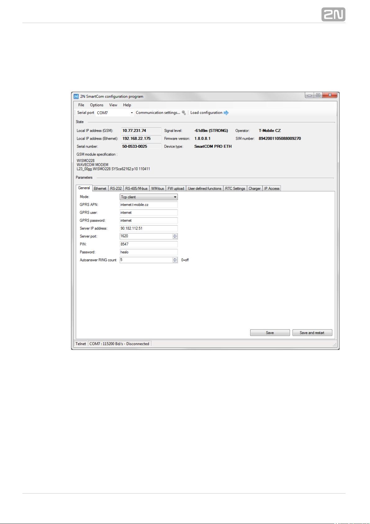
Application Details
Figure: Terminal Config Window
The figure above shows the Terminal Configuration Program2N SmartCOM
®
(hereinafter referred to as Terminal Config) window. The main toolbar helps you select
the for connection to (hereinafter referred to asSerial port 2N SmartCOM
®
terminal). This list includes all available serial ports installed in the PC on which the
application is running.
®
672N TELEKOMUNIKACE a.s., www.2n.cz
Page 68

Figure: Communication Settings
Having selected a port, set the communication parameters to adjust communication
rates and signal transmission parameters for the serial port. The fact2N SmartCOM
®
ory values are set here by default. Refer to the figure Communication Settings
above.
No password is requested by default for the RS-232 port and so nothing has to be filled
in. Passwords may be different for different terminals. If a password is requested, enter
the password into the dialogue window displayed during the connecting process. The
last main toolbar button helps you from the terminal connected -Load configuration
the application gets connected and reads out all relevant data.
Tip
The application connects to the selected terminal, identifies the
RS-232 mode (DATA or COMMAND), switches the port as necessary,
reads out the data, switches the port into the original mode and
terminates communication. This gives the other users continuous
access to the terminal.
The section displays the most important information on the given device.State
The IP address, serial number, firmware version, logged-in provider and signal level
are displayed. The SIM ICCID (Integrated Circuit Card ID) is displayed, which is not the
®
682N TELEKOMUNIKACE a.s., www.2n.cz
Page 69

SIM telephone number, i.e. MSISDN, but a unique SIM serial number. There are no two
identical ICCIDs at one moment. These 19-digit numbers start with 8942 for the Czech
Republic.
Moreover, the section provides information on the GSM module: type, manufacturer
and firmware version.
The section helps you view and set parameters for the tParameters 2N SmartCOM
®
erminals. Refer to for application use details.Subs. 6.1
Use the menu to read configuration, import/export configuration or reset theFile
connected terminal. Via the menu you can adjust communication parameters Options
and/or change the default language (CZ or EN). The section helps you disableView
the tags that are not frequently used and occupy too much space. Open the View menu
and specify the tag(s) to be seen.
Tip
The tag is always visible. It is the only menu that cannot beGeneral
disabled.
Figure: View Menu
Go to to know details on the Terminal Config manufacturer and version.Help
®
692N TELEKOMUNIKACE a.s., www.2n.cz
Page 70
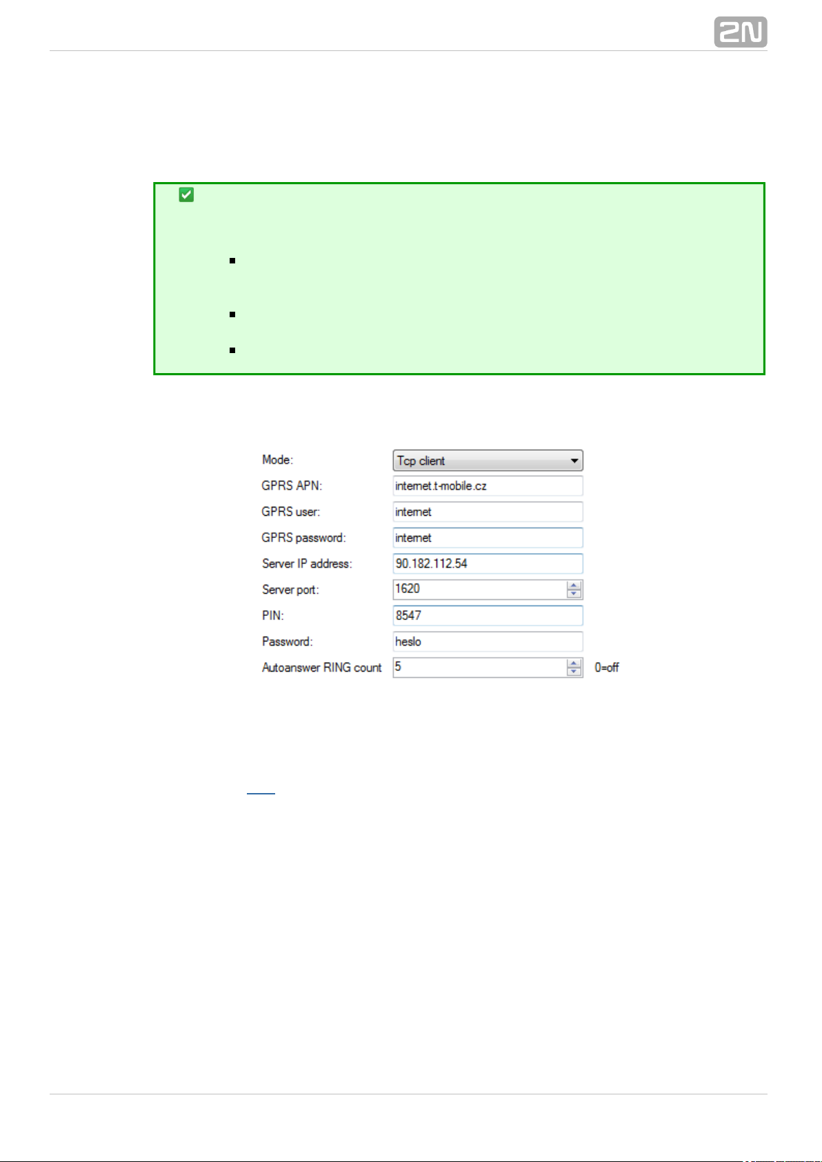
Application Use
Tip
Not all tags are accessible to all device models.
General, RS-232, RS-485/M-Bus, Error buffer, Own AT
and commands, FW upload, User defined functions IP access
are accessible to all terminals.
and are available to the WM-Bus, RTC settings Charger SC PRO
and terminals only.SC PRO ETH
is accessible to the terminals only.Ethernet SC PRO ETH
Having read configuration, go to the tag of the section.General Parameters
Figure: General Menu
Here you can set all parameters comfortably as you can with the AT commands
described in , i.e. GSM commands plus automatic answer parameters. Push tS. 4 Save
o save the values. Push to apply the changes immediately.Save and restart
The Ethernet menu is only available to terminals equipped with an Ethernet port. Set
the primary data flow channel, LED signalling functions, obtaining IP address from the
DHCP server or static obtaining and DNS server use.
®
702N TELEKOMUNIKACE a.s., www.2n.cz
Page 71

Figure: Ethernet Menu
Use the RS–232 and RS485/M–Bus tags to set communication parameters for each
port. Set the password request enable and AT mode upon power up for RS-232. Use
the WM-Bus tag to set the operating and decryption modes for the module.
®
712N TELEKOMUNIKACE a.s., www.2n.cz
Page 72

Figure: WM-Bus Menu
Click on the required item in the to select a device andList of configured devices
push the buttons to the right to remove the item or add the decryption key.
Caution
The keys are added to the WM-Bus module directly for security
reasons and are not displayed in the configuration. Therefore, be
careful while configuring the keys.
A key adding error may lead to a decryption error.
Furthermore, you can to the list. Enter the device code and serialAdd new device
number. Complete the timeout, e.g., in case the selected device sends multiple
identical pieces of information in a short time interval. The remaining parameters are
optional and need not be specified.
Warning
Contact the device manufacturer for precise identification details.
Enter all the identification parameters of the new device to enable
encryption in the device.
®
722N TELEKOMUNIKACE a.s., www.2n.cz
Page 73

Display received messages in the section. The messages are read fromGet message
the database starting with the oldest one. The Message count parameter displays the
count of received messages in the terminal and the amount of free space. When there
is no free space, the oldest record will be deleted to make space for a new message.
Push the button to export all the messages stored in the terminalExport messages
into a PC file in order to make space for new messages.
The helps you display the error codes captured during the operation. IfError buffer
no error has occurred since the last clearing date, ^SCERR: NO ERROR will be
displayed. If an error occured, the error code will be displayed. Click on the Error code
table button to display the message decryption window.
Figure: Error Buffer
Use the tag to enter commands of your own for parameterOwn AT commands
setting. The tag behaves like a terminal. Enter a string into the AT command field
corresponding to the supported commands listed in . Click on to sendSubs. 4.2 Send
the command to the connected unit and get the reply in the field2N SmartCOM
®
below the command. A list of 20 last-applied commands is displayed to the right.
®
732N TELEKOMUNIKACE a.s., www.2n.cz
Page 74
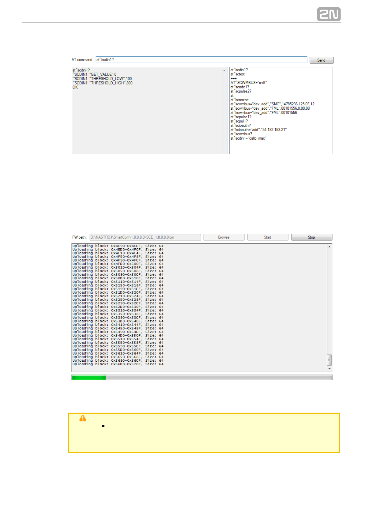
Figure: User Defined AT Commands
The last tag helps you upgrade firmware via the terminal COM port. Select the path to
the current firmware file and press to initiate the upgrading process, which isStart
signalled by the progress bar below. When the process is completed, the terminal will
get restarted.
Figure: FW Upload
Caution
Make sure that the terminal FW supports FW upgrade via the COM
port to make the process successful. The minimum terminal FW
version must be 1.4.0.
®
742N TELEKOMUNIKACE a.s., www.2n.cz
Page 75
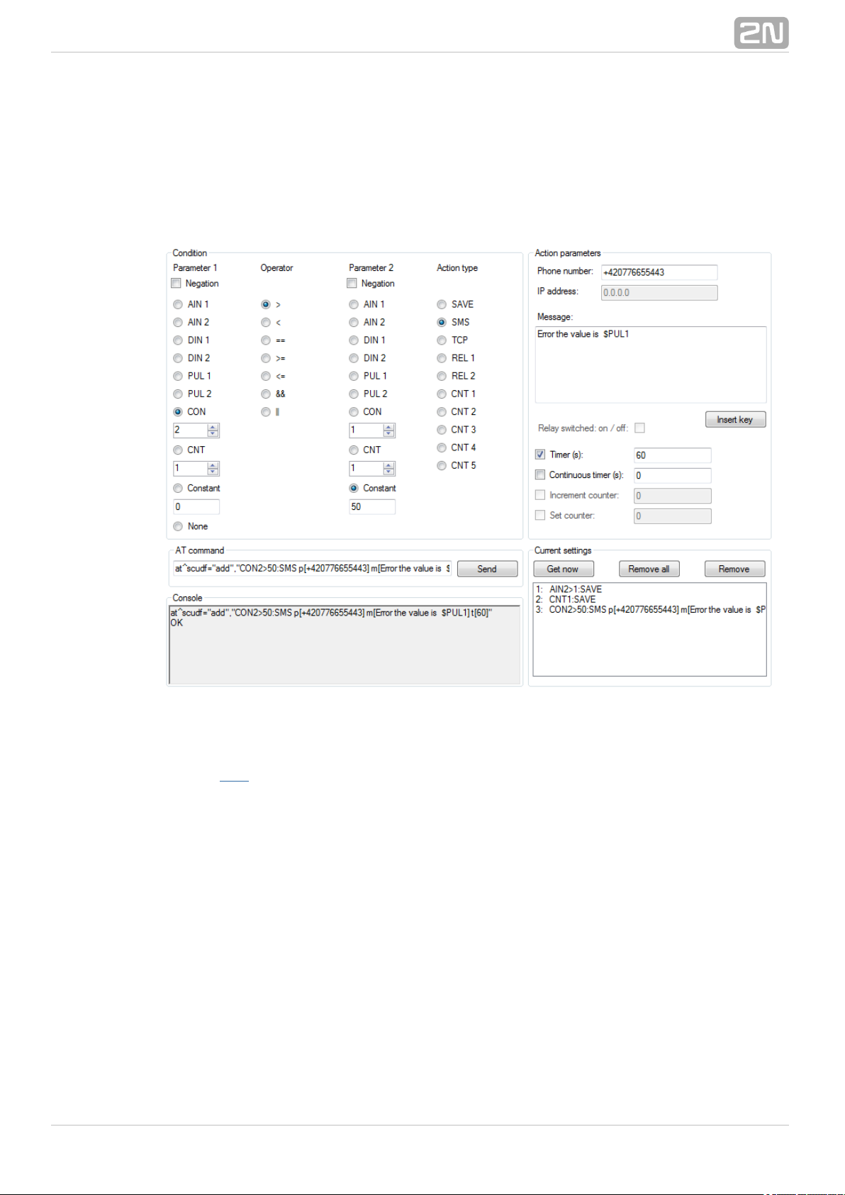
The tag helps you set the UDF graphically and more easily inUser defined functions
the application than using an AT command in the terminal. Just select the required
functions and set their parameters and the application itself will generate the relevant
AT command to be sent to the terminal, or to be stored for later use. Refer to Console
for the current terminal communication listing and to for the list ofCurrent settings
configured commands in the terminal.
Figure: User Defined Functions Menu
Refer to for more details on the UDF setting options. S. 9
The tag displays the current date, time and time zone data. You can alsoRTC settings
synchronise the device time with your PC time, or set the device time manually. Click
on to confirm the settings.Save
®
752N TELEKOMUNIKACE a.s., www.2n.cz
Page 76

Figure: RTC Settings Menu
is another setting option. It displays the back-up battery charging state forCharger
the terminals. You can enable/disable the function and set the maximumSC PRO
charging voltage and current.
Figure: Charger Menu
is the last accessible tag. You can define from which IP addresses it will beIP access
possible to access the terminal. Attempts from non-listed IP addresses will be ignored.
Press to enable the function and to add an IPv4 address to the list. Click on an ON Add
item for selection and push to delete an address from the list.Remove
®
762N TELEKOMUNIKACE a.s., www.2n.cz
Page 77
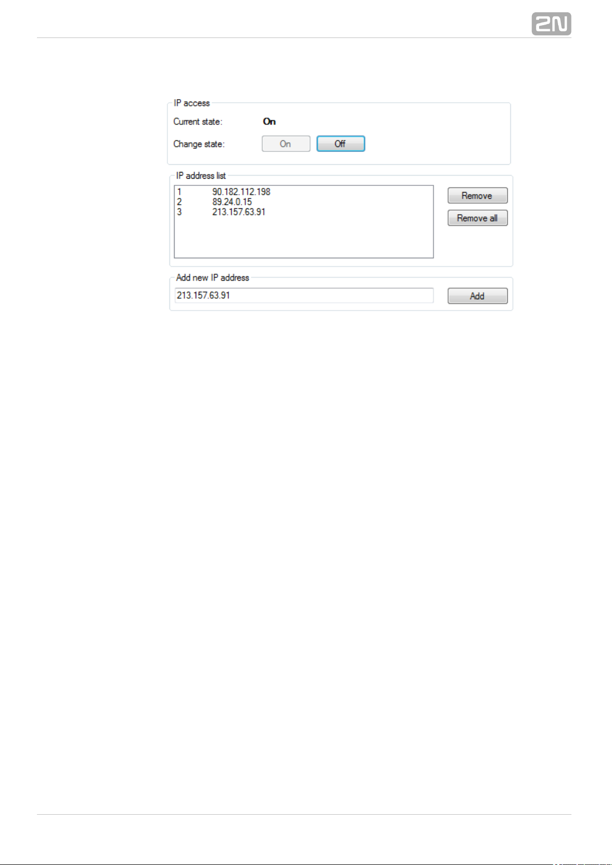
Figure: IP Access Menu
®
772N TELEKOMUNIKACE a.s., www.2n.cz
Page 78

7. Control Panel
In this section, administration and use of the product using the 2N SmartCOM
®
2N
®
Server and Control Panel are described. SmartCOM 2N SmartCOM
®
Here is what you can find in this section:
7.1 SC Server
7.2 Control Panel
7.3 Control Panel Use
®
782N TELEKOMUNIKACE a.s., www.2n.cz
Page 79
7.1 SC Server
2N SmartCOM® Server is an application necessary for the Control2N SmartCOM
®
Panel operation, providing communication between the Control Panel2N SmartCOM
®
and the terminal.
Caution
The Server must be installed on a PC accessible from2N SmartCOM
®
a public Internet. Or, a NAT rule has to be defined to provide access to
such PC. Otherwise, the terminals cannot be connected to the 2N
®
Server. You can select the ports to be forwarded to your SmartCOM
LAN via the NAT during installation.
Installation
Once launched, the installation program will scan your PC. If it finds another 2N
®
Server version, it will ask you whether to uninstall. If you select No, the SmartCOM
wizard will be terminated. If you select Yes, the current Server2N SmartCOM
®
version will be removed. Then you will be asked whether or not to remove the
configuration files. If you select No, the current configuration will be retained and the
application will only be updated.
Now the Server Setup Wizard is launched. Follow the wizard2N SmartCOM
®
instructions. Select the directory for the Server to be installed. By2N SmartCOM
®
default, C:\Program Files\ SC Server is2N TELEKOMUNIKACE\2N SmartCOM\
® ®
used.
Also select the port for the application to communicate with the terminals and other 2N
Control Panel applications. Make sure that the port is accessible from the SmartCOM
®
Internet (see above) and properly configured in all terminals and applications. Http
accessibility is necessary as the selected port provides a listing of LOG files and can be
used for firmware downloading to terminals. Firmware is downloaded whenever
upgrade is initiated by the Control Panel or the address is entered2N SmartCOM
®
into the terminal.
Here you can also set the port for the AT API; refer to S. 8 for details. Now the wizard
is ready to install the Server. It displays the list of settings. Check the2N SmartCOM
®
set parameters carefully as the values cannot be changed without reinstallation when
the installation has been completed! If you find an error, push the button toBack
return to the respective window. If all the settings are OK, push to continue.Install
The wizard now installs the Server. Server2N SmartCOM
®
The 2N SmartCOM
®
service is launched automatically after installation. If the automatic launch fails for any
reason, launch the service manually. Now the Server is ready for2N SmartCOM
®
use.
®
792N TELEKOMUNIKACE a.s., www.2n.cz
Page 80

Note
The Server requires of free disk space at 2N SmartCOM
®
500 MB
least for installation.
Use the 2N SmartCOM Control Panel application to make
®
changes in the 2N SmartCOM Server settings®.
Licencing
All the Server functions are subject to licence. For your first2N SmartCOM
®
installation of the application onto your PC, you will receive the trial licence for 800 h
operation and connection of 2 users and 2 terminals.
Caution
The clock counter is increased by 1 by every Server2N SmartCOM
®
restart.
The Licence Tool is installed together with the server. Having2N SmartCOM
®
launched the application, you can see the version, ID and details on service settings for
the server installed. See Figure.
Figure: Licence Tool
A unique ID is generated for your server during installation. Send this code including
your licence requirements to for an extended licence. sales@2n.cz
Having received the licence file, launch the Licence Tool application and enter the path
to this file into the parameter. Push to add the licence to theLicense path Upload
server directory and restart the server to update the licence data. The licence status
®
802N TELEKOMUNIKACE a.s., www.2n.cz
Page 81

will change into OK. Now, the last row of the includes all theListing parameters
licensed server properties: count of users, count of terminals and AT API and terminal
upgrade enable.
®
812N TELEKOMUNIKACE a.s., www.2n.cz
Page 82

7.2 Control Panel
The Control Panel provides a comfortable administration of terminals 2N SmartCOM
®
and users/user groups and assigns users relevant communication and administration
rights. Also, it can create virtual TCPs and serial ports and connect terminals to them.
Caution
The Control Panel uses the English language version2N SmartCOM
®
only.
Installation and Sign–In
Once launched, the installation program will scan your PC. If it finds another 2N
®
Control Panel, it will ask you whether to uninstall or modify it. If you SmartCOM
select Uninstall, the current Control Panel version will be uninstalled.2N SmartCOM
®
Now the Control Panel Setup Wizard is launched. Follow the Wizard2N SmartCOM
®
instructions. Select the directory for the Control Panel to be installed.2N SmartCOM
®
By default, C:\Program Files\ \ is used.2N TELEKOMUNIKACE\2N SmartCOM
® ®
Also, select whether the application shall be installed for the currently signed–in user or
all PC users.
Now the wizard is ready to install the Control Panel. It automatically2N SmartCOM
®
adds an item to the menu and the application icon to the desktop.Start
Note
The Control Panel requires of free disk2N SmartCOM
®
150 MB
space at least for installation.
Now the Control Panel is ready for use. Click on the shortcut icon on2N SmartCOM
®
the desk top (see Fig. 7.1) or select the menu option to launch the application.Start
Upon the first launch, you will be asked to enter the username and password and then
the server and server listening port. After you do so, use the item.Sign in
Figure: 2N SmartCOM Control Panel Icon
®
®
822N TELEKOMUNIKACE a.s., www.2n.cz
Page 83

Caution
Important! A default user with the Administrator login was created
during the Server installation to make it possible to2N SmartCOM
®
connect to the server and configure all the other users. The default
user login data are as follows:
Username:Admin
Password: 2n
If you use one and the same PC for the Control Panel and the 2N SmartCOM
®
2N
®
Server, you can enter the local loop address 127.0.0.1 or the local host SmartCOM
text as the server address. To log in to another server, enter the local or public IP
address. Or, use the DNS names if you use DNS. Enter the listening port into the iPort
tem as selected during your Server installation. Contact you network2N SmartCOM
®
administrator for correct settings.
Figure: Sign–In Window
The encryption settings are in the right-hand bottom corner. Click on Change
encryption key to display the encryption setting window. If the server requires so,
enable packet encryption and set the key. Enter the key either in the ASCII format,
where HEX is completed automatically with the translated characters, or enter the
®
832N TELEKOMUNIKACE a.s., www.2n.cz
Page 84

HEXA key. The key length is 16 ASCII / 32 HEXA characters. Press OK to sign in with
applied encryption. A message will notify a key error if any or encryption options if
supported by the server.
Figure: Encryption Settings
Introduction to Application
You will be shown the application layout and main controls in this subsection. The
application can be viewed in two ways: the and the . TheUser mode Admin mode
User may see the menus necessary for its work with terminals only. The Administrator
also views the user/user group managing and server setting menus.
The line displays the following information: From the left: application version,Status
currently signed–in user, count of configured terminals, count of on–line terminals,
current server address, server listening port and application status.
Find the button in the bottom part.Sign–out
®
842N TELEKOMUNIKACE a.s., www.2n.cz
Page 85

Figure: Application Window
®
852N TELEKOMUNIKACE a.s., www.2n.cz
Page 86

Basic Controls
Push the button to return to the main menu.Home
Click on to update the status of objects inRefresh
the selected menu,
e.g. the terminal status in the or Terminals
menu.Connections
Push these buttons to / communicationStart Stop
with the terminal.
Push the Add user button to add a user..
Push the button to add a user group.Add group
Push the general button to add an object to aAdd
group and create new virtual ports and terminals.
Click on to modify the parameters alreadyEdit
configured.
Click on to remove an object fromRemove
configuration.
The button changes the userChange password
password and may be used by the Administrator
only.
®
862N TELEKOMUNIKACE a.s., www.2n.cz
Page 87

Push the button to create new objects.Create
Click on the button to clear the currentlyCancel
made changes.
Click on to save the currently made changesSave
and send them to the Server2N SmartCOM
®
configuration.
Use this button to install the virtual serial port
driver.
Push the button to log out the currentlySign out
signed–in user.
Use to search the relevant table columns.Search
Use / to control the relaySwitch on Switch off
contacts.
Use the button to display details on the terminal.
Click on to upgrade firmware of selectedUpdate
terminals.
Click on to reset the factory default valuesDefault
for all parameters.
®
872N TELEKOMUNIKACE a.s., www.2n.cz
Page 88

7.3 Control Panel Use
The main purpose of the Control Panel is to virtualised ports and2N SmartCOM
®
facilitate connection to terminals. The application also provides comfortable
administration and user management including assignment of terminal administration
rights, thus allowing users to manage a high number of terminals from one place as
well as assign small terminal groups to authorised users.
User Mode
Having singed in as the User, you get access to four items of the main menu only:
, , and . They are all you need forTerminals Connections Virtual Ports Settings
standard work with the terminals. You have been assigned to one of the groups by the
Administrator and so you are allowed to view the terminals assigned to this group only.
See below for details on the menus.
Terminals
Figure: User Mode Terminals Menu
The menu displays the terminals assigned to the group you have the rightTerminals
to view.
®
882N TELEKOMUNIKACE a.s., www.2n.cz
Page 89
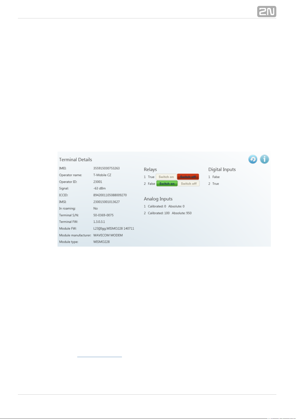
A green dot before the terminal means that the terminal is on–line (connected to the
server) and you can get connected to it. A red dot means that the terminal is off–line.
Click on a selected terminal on the right to display the windowTerminal Details
including the name, serial number, hardware revision number and count of available
relays and digital and analogue inputs. Notes are also displayed on the terminal if
available.
If you are a user, you can select a virtual port for terminal connection. The Virtual
can fully be administered by the user; refer to the subsectionports Virtual Ports
below. If you select an unoccupied port, the port will be marked 'in use' signalling to
the other users that the port is engaged in the configuration.
If you have the appropriate user right, you can also set the communication parameters
for the selected port including the transmission rate and others even if the terminal is
connected and used for data transmission. Select the parameters using the combo
boxes and the changes will be effective the moment they are saved.
Click on the button in on–line terminals to display details on the connectedInfo
terminal, relay control and values measured on analogue and digital inputs.
Figure: Terminals Menu Terminal Details
The include the following data: GSM module IMEI (InternationalTerminal Details
Mobile Equipment Identity), name and number of the GSM provider at which your 2N
®
is registered, signal intensity in dBm, ICCID (Integrated Circuit Card ID) SmartCOM
and IMSI (International Mobile Subscriber Identity). The In roaming parameter
indicates whether the SIM card is used in the roaming mode. Moreover, the 2N
®
terminal serial number and current firmware as well as information SmartCOM
(firmware version, manufacturer and type) on the GSM module used are displayed.
You can switch the relay contacts in the section. The displaysRelays Digital Inputs
the value currently measured at the input and transformed to a logic value (0 or 1) as
calibrated. The displays the values measured at analogue inputs.Analogue Inputs
The Calibrated and Absolute parameters include the percentage against the calibrated
range and the absolute value against the A/D converter range respectively.
Refer to , Input Circuits, for more details on input circuit function andSubs. 3.3 and 3.4
calibration.
®
892N TELEKOMUNIKACE a.s., www.2n.cz
Page 90
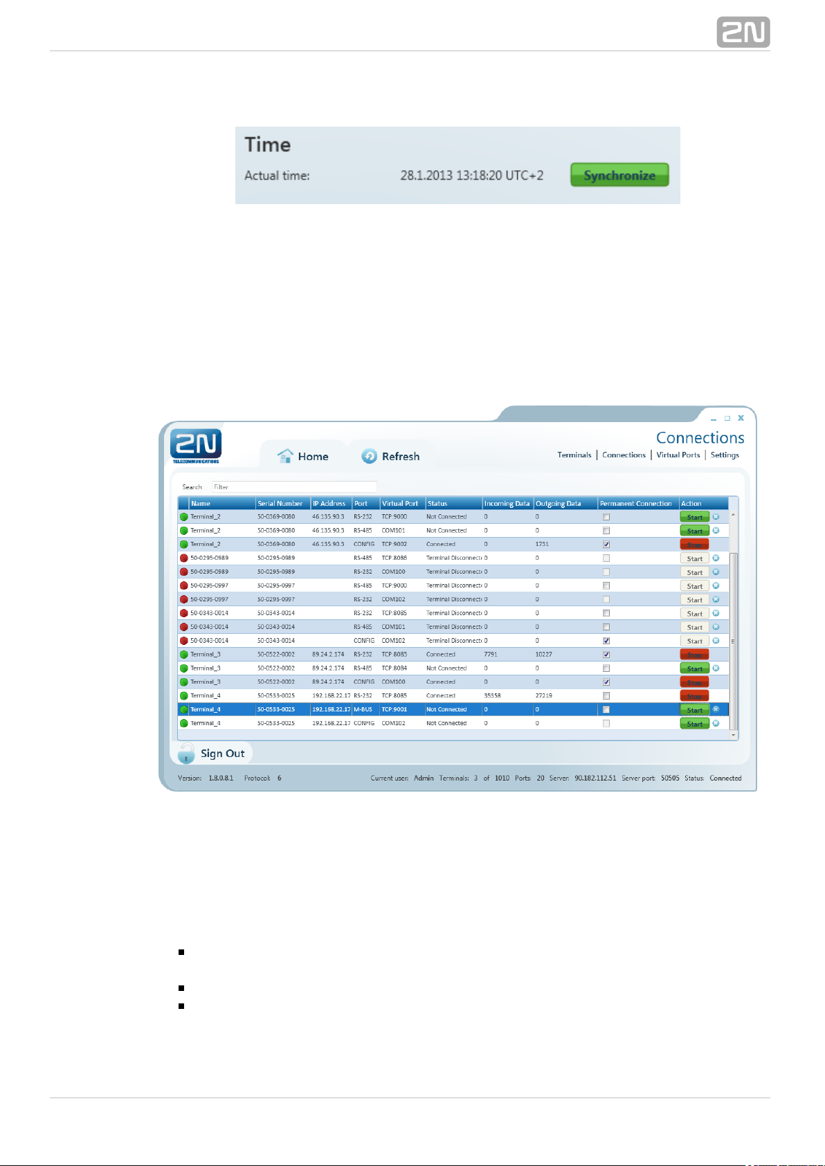
Figure: Terminal Time Synchronisation
The time setting supporting and terminals also display the terminalPRO PRO ETH
time. Click on to set the same time value for the terminal as there is inSynchronize
the server.
Connections
Figure: Connections Menu
The menu contains a table showing the terminals that are assigned aConnections
virtual port. The table includes the terminal name, serial number, IP address and
physical port to be connected to the selected virtual port. The field defines theStatus
current of the terminal:
- the terminal is on-line connected to the server and ready forNot Connected
virtual port connection.
- the terminal - virtual port connection is in progress.Connecting
- the terminal has been successfully interconnected with the virtualConnected
port.
®
902N TELEKOMUNIKACE a.s., www.2n.cz
Page 91
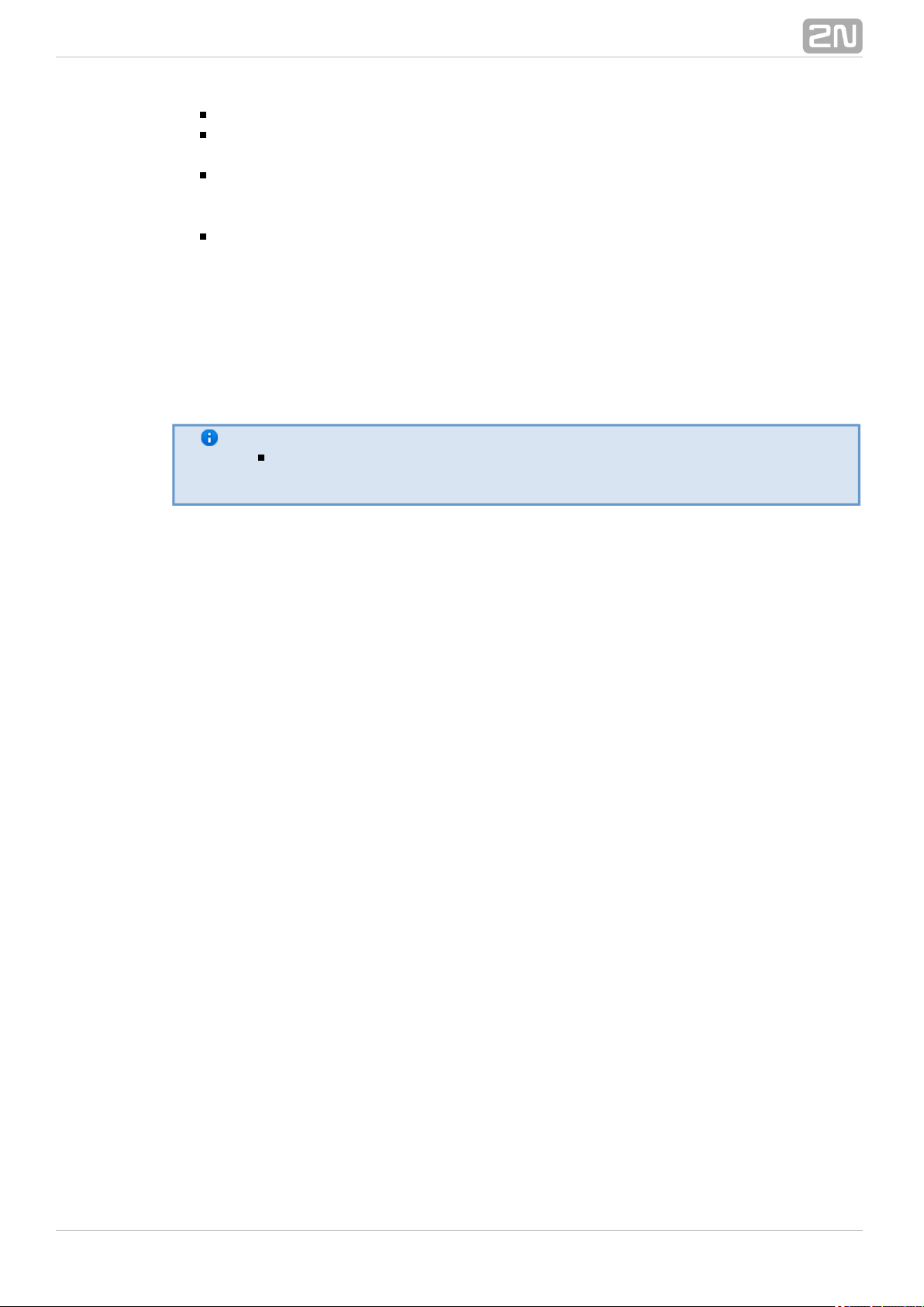
- disconnection from the virtual port is in progress.Disconnecting
- the terminal is off-line, i.e. has been disconnectedTerminal Disconnected
from the SC server.
- the terminal has been disconnected by anotherDisconnect by other user
user. This means that the other user has interconnected its virtual port with this
terminal.
- an error occurrred during connection or disconnection.Error
The and fields display the amount of data transmitted in Incoming Outgoing Data
the given direction and are for information only. Check off toPermanent connection
enable automatic terminal connection to the virtual port upon the application start.
Press to interconnect the terminal with the virtual port. If one and the same portStart
is used by multiple terminals, the other users will not be able to press until theStart
first connection has been finished. Refer to the note below. Push to terminateStop
communication.
Note
Although there may be multiple terminals assigned to a virtual port,
one terminal can only be assigned to the port within one connection.
In case another user is connected to the terminal, the button has an orangeStart
background colour. You can push the button to disconnect the original user and
connect the terminal with your virtual port.
Use the cross to remove the selected row from the table, thus cancelling
interconnection between the virtual port of the application and the physical port of the
terminal easily.
®
912N TELEKOMUNIKACE a.s., www.2n.cz
Page 92

Virtual Ports
Figure: Virtual Ports Menu
Administer virtual ports using the menu. Every user can use this menuVirtual Ports
as these settings only relate to the PC with which the user is working. This means that
where more PCs are used, the user must create the virtual ports for each of them.
This, however, applies to serial ports only; virtual ports are transferable to other PCs.
This option, however, can be disabled in the configuration.
Create TCP Port
To create a virtual TCP port, select and enter the port to be created. Also, tick off Add
to enable the port use for the current PC only. Finally, click on Allow local host only
.Create
Figure: Create TCP Port
Create COM Port
A virtual COM port is created similarly as instructed above. Just select a port and click
®
922N TELEKOMUNIKACE a.s., www.2n.cz
Page 93

on to make the com0com driver install the selected port into the PC.Create
Figure: Create COM Port
Having installed a COM port into the PC, activate the COM port. Although the port has
been added to the table, the item shows NO. Therefore, click onVirtual ports Ready
this table row to view the port details and the button. Push the button toRefresh
change the port status from Ready – NO to Ready – YES.
Figure: Refresh Button
®
932N TELEKOMUNIKACE a.s., www.2n.cz
Page 94
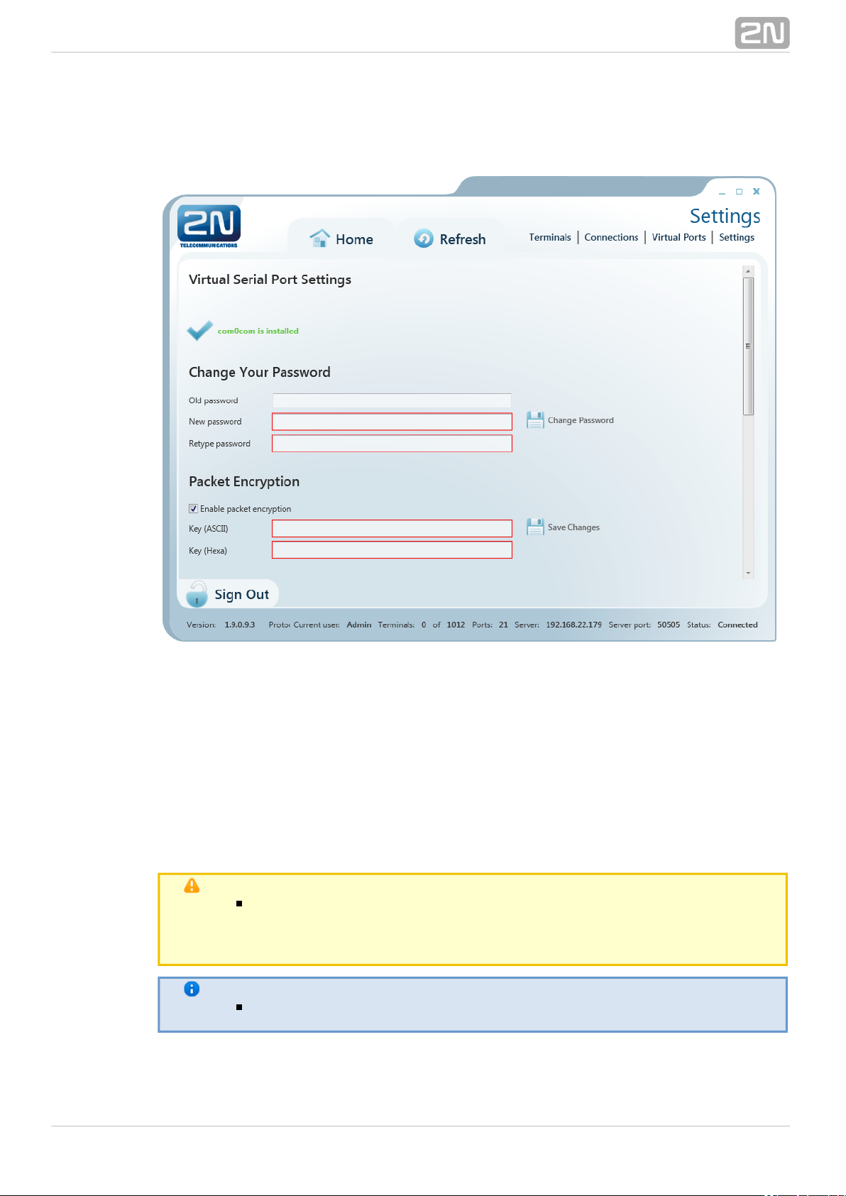
Settings
Figure: Settings Menu
You can change the user password in the menu. Enter the old password andSettings
then the new one. The minimum password length and correctness is checked by the
parameters. Save the setting using the button.Change password
The menu also displays the installation states of the virtual serial port drivers. If no
drivers have been installed, you cannot use or add serial ports in the meVirtual ports
nu. If the com0com driver is not installed, the 'com0com is not installed' message gets
displayed as shown in Figure. You can install drivers for 32 and 64–bit systems too.
If the installation process is successful, the 'com0com is installed' will be displayed.
Caution
You need the Admin rights for the PC used for com0com installation. If
you do not have such rights currently, the installation will offer you an
Admin login option.
Note
The installation requires of free disk space at least.0.5 MB
The menu also includes encryption key settings for server communication, like in the
®
942N TELEKOMUNIKACE a.s., www.2n.cz
Page 95
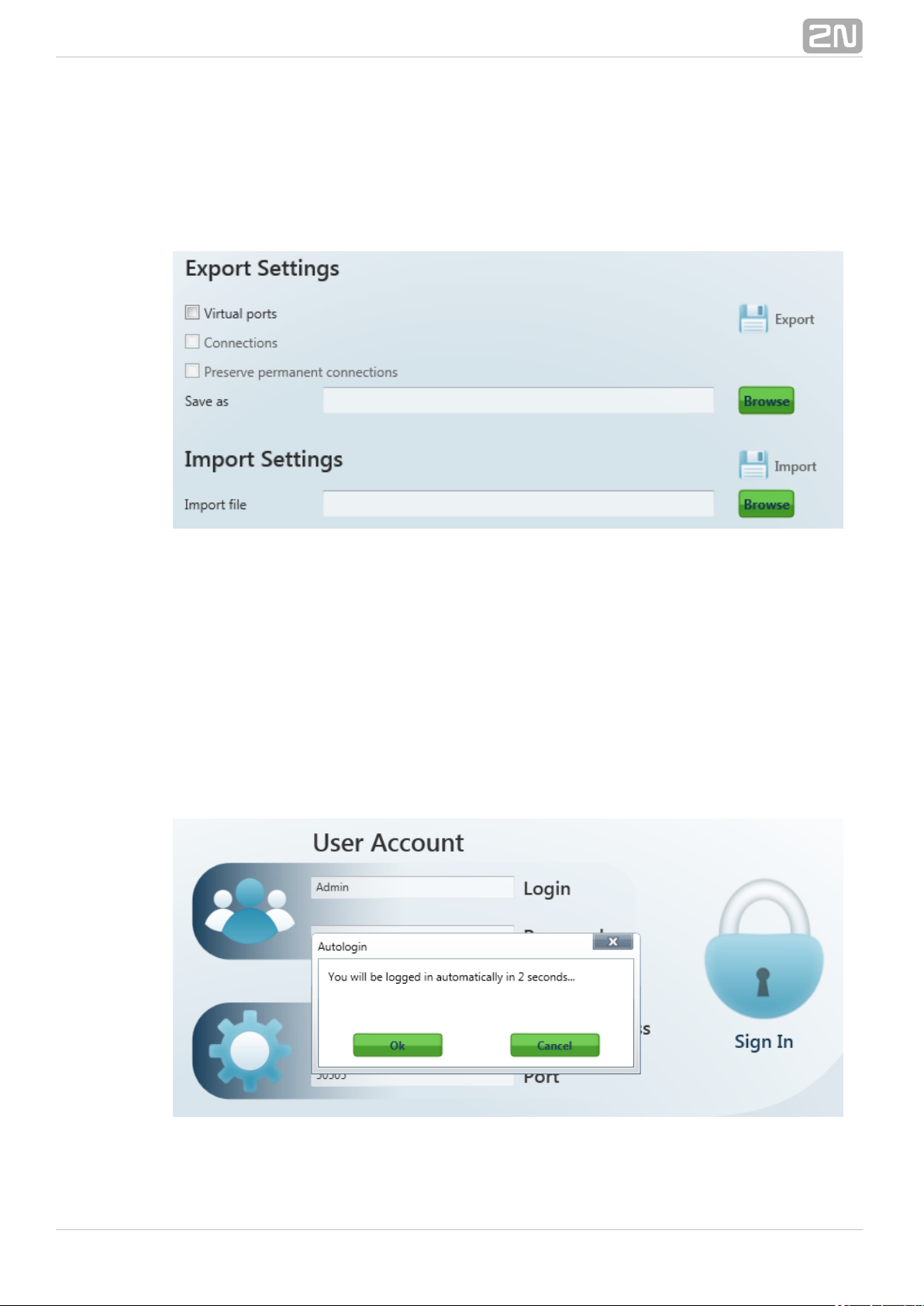
sign-in window. Tick the checkbox to enable packet encryption. Enter the selected key
into the Key field and save the setting. The setting will not be applied until you sign
out. Moreover, you can set the configuration export/import options. Select the Virtual
ports, Connections and/or Permanent connections in the Export Settings item to
transfer your configuration to another PC. Choose the export destination and press
Export to execute the operation.
Figure: Setting Export / Import
To import your configuration, sign in as the user to which you want to import the
settings. Make sure that this user is identical with the user from which export was
made to create a correct configuration file. Now you can load the new configuration
onto any account. Select the file to be imported and press Import to import the data.
The change will be applied when the user signs out and in.
Moreover, you can set in this menu. If you enable this function,Automatic sign-in
the application will automatically log in to the server within a preset time interval. If
you interrupt autologin in this interval, you can change the login data and sign in as
another user, or to another server.
Figure: Autologin
®
952N TELEKOMUNIKACE a.s., www.2n.cz
Page 96

Caution
By interrupting automatic login you also disable the Allow automatic
parameter. Thus, you will have to re-enable it to use autologinlogin
again.
The application checkbox helps you debug the application or just record Logging
server communication.
The files are automatically split after reaching 10MB.
Admin Mode
The Admin user has access to all User mode menus plus the user and terminal
administering and server setting menus. The menu includes the , Admin mode Users
, , and menus.Groups Links Terminals, Server Settings Firmware Management
See the subsections below for details.
Users
Figure: Users Menu
The menu is used for user administration. The list of users is on left. A green dotUsers
before the user name means that the user is on–line (connected to the 2N
®
Server). A red dot means that the user is off–line (logged out). SmartCOM
®
962N TELEKOMUNIKACE a.s., www.2n.cz
Page 97

Click on the user to display the including the full name, login, notes andUser Details
Admin flag if available. By clicking on , the Administrator canChange password
change any user password without knowing the original one. This is mainly useful for
those users who forget their passwords. Click on to change the user details.Edit
The menu contains the user groups to which the user is assigned. Click on Groups
and select an item from the list to create a new group. Push to remove aAdd Remove
group from the list.
Add user
Click on the button next to the filter setting. You will be asked to completeAdd user
the login, full user name and password to ensure a proper function. The parameters
are limited and you will be checked during entering. No name or login may be
duplicated in the configuration. You will be notified of any duplication in the
configuration. You can also add a note and/or the Admin mode to the user by ticking of
the option. Click on to create a new user.Is Administrator Create
Groups
Figure: User Groups Menu
The menu helps you group users and terminals. As it is unnecessary for allGroups
users to view and manage all terminals, you can create small user groups for terminal
data reading and administering.
Click on a group to display the including the full group name, notes ifGroup Details
any and rights assigned to the group. Click on to change these parameters.Edit
There four group right categories:
®
972N TELEKOMUNIKACE a.s., www.2n.cz
Page 98

Read – users with the right may view the terminals and monitor theirRead
states without being able to configure then or connect to them.
Connect – users with the right may view and also connect to theConnect
terminals via the menu.Connections
Configure – users with the right have the advantages of the twoConfigure
user groups above and, moreover, may configure the communication parameters
of the terminal ports.
Monitor – not implemented yet. Prepared for future use.
Use the menu to add/remove the terminal to be viewed by the usersTerminals
assigned to this group. Click on and select an item from the list to add a terminal.Add
Click on to remove a terminal from the list.Remove
The menu includes a list of users assigned to this group. Click on and selectUsers Add
an item from the list to add a user. Click on to remove a user from the list.Remove
Add Group
Click on the button next to the filter setting. You will be asked to completeAdd group
the group name and rights to ensure a proper function. The parameters are limited and
you will be checked during entering. No name may be duplicated in the configuration.
You will be notified of any duplication in the configuration. You can also add a note to
the group. Click on to create a new group.Create
Links
Figure: Links Menu
The menu displays the currently connected terminals and users. TheLinks
Administrator can supervise and disconnect them if necessary. The table includes the
®
982N TELEKOMUNIKACE a.s., www.2n.cz
Page 99

serial number, IP address and port of the selected terminal, the user currently working
with the terminal, the user IP address and active port. Find the button in the Stop
field.Action
Tip
The button is used for unconditional disconnection of a terminalStop
from the virtual ports regardless of the data transmission state.
Terminals
Figure: Admin Mode Terminals Menu
The menu in the Admin mode is similar to that in the User mode but isTerminals
extended by group assignment, terminal adding and terminal editing options.
A green dot before the terminal means that the terminal is on–line (connected to the
server) and you can get connected to it. A red dot means that the terminal is off–line.
Click on a terminal in the right–hand part of the screen to display the Terminal
including the terminal name, serial number, hardware version as well as countDetails
®
992N TELEKOMUNIKACE a.s., www.2n.cz
Page 100
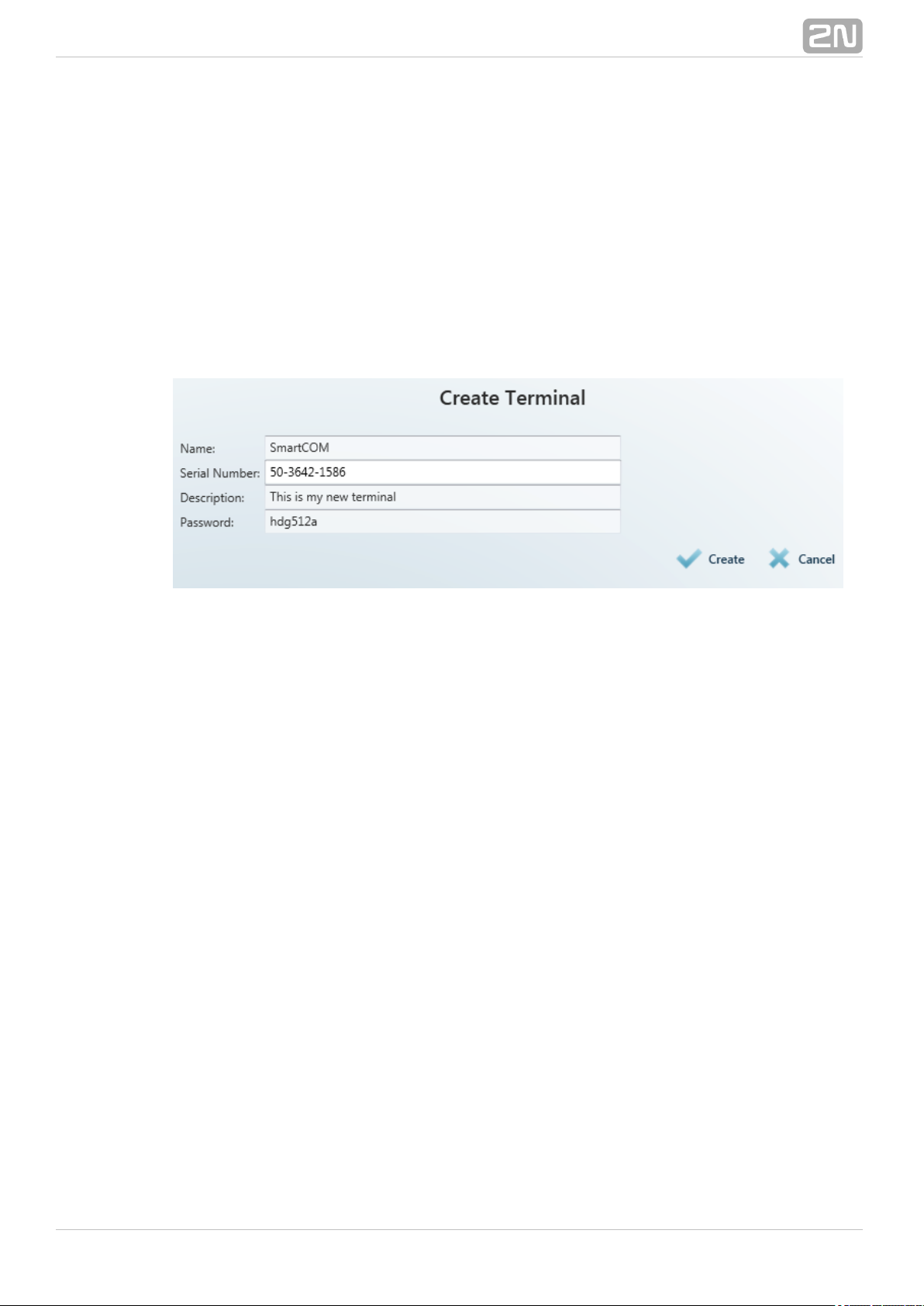
of available relays and digital and analogue inputs. Notes can be added if available.
Click on to change the terminal details.Edit
Specify in the in which group the selected terminal shall be visibleTerminal Groups
(i.e. which group shall be allowed to use this terminal). Click on to add a group.Add
Click on to remove a group from the list.Remove
You can also set communication for the RS–232 and RS–485/M–BUS ports even if the
terminal is connected and used for data transmission. Select the parameters using the
combo boxes and the changes will be effective when saved.
Create Terminal
Click on next to the filter to create a new terminal.Add terminal
Figure: Create Terminal
To add a terminal, enter the terminal name, serial number and password. The
parameters are limited and you will be checked during entering. No name or serial
number may be duplicated in the configuration. You will be notified of any duplication
in the configuration. Click on to create a new terminal. Create
®
1002N TELEKOMUNIKACE a.s., www.2n.cz
 Loading...