


 Loading...
2N® Indoor Touch 2.0
|
|
User guide |
Firmware: |
4.2.2 |
|
Version: |
4.2.2 |
www.2n.cz |
The 2N TELEKOMUNIKACE a.s. is a Czech manufacturer and supplier of telecommunications equipment.
The product family developed by 2N TELEKOMUNIKACE a.s. includes GSM gateways, private branch exchanges (PBX), and door and lift communicators. 2N TELEKOMUNIKACE a.s. has been ranked among the Czech top companies for years and represented a symbol of stability and prosperity on the telecommunications market for almost two decades. At present, we export our products into over 120 countries worldwide and have exclusive distributors on all continents.
2N®is a registered trademark of 2N TELEKOMUNIKACE a.s. Any product and/or other
names mentioned herein are registered trademarks and/or trademarks or brands protected by law.
2N TELEKOMUNIKACE a.s. administers the FAQ database to help you quickly find information and to answer your questions about 2N products and services. On www. faq.2n.cz you can find information regarding products adjustment and instructions for optimum use and procedures „What to do if...".
2N TELEKOMUNIKACE a.s. hereby declares that the 2N product complies with all basic requirements and other relevant provisions of the 1999/5/EC directive. For the full wording of the Declaration of Conformity see the CD-ROM (if enclosed) or our website at www.2n.cz.
The 2N TELEKOMUNIKACE a.s. is the holder of the ISO 9001:2009 certificate. All development, production and distribution processes of the company are managed by this standard and guarantee a high quality, technical level and professional aspect of all our products.

Content:
 1. Product Overview
 1.1 Product Description
 1.2 Differences between Models
 1.3 Terms and Symbols
 1.4 Safety Precautions
 2. Description and Installation
 2.1 Before You Start
 2.2 Brief Installation Guide
 2.3 Installation Conditions
 2.4 Status LED
 2.5 First Startup
2N TELEKOMUNIKACE a.s., www.2n.cz |
3/135 |

 3. 2N® Indoor Touch 2.0 Configuration
 3.1 Factory Reset
 3.2 Home Screen
 3.3 Device Configuration
 3.3.1 User Settings
 3.3.1.1 Device
 3.3.1.2 Personal
 3.3.1.2.1 Security
 3.3.1.2.2 Language and Input Methods
 3.3.1.3 System
 3.3.1.3.1 Date & Time
 3.3.1.3.2 Backup & Reset
 3.3.2 Administrator Settings
 3.3.2.1 Device
 3.3.2.2 Wireless & Networks
 3.3.2.3 Security
 3.3.2.4 Backup & Reset
 3.3.3 Intercoms
 3.3.3.1 General Settings
 3.3.3.2 Call Settings
 3.3.3.3 My2N/SIP Configuration
 3.3.3.4 Video
 3.3.3.5 Recorder
 3.3.3.6 Input and Output
 3.4 Device Upgrade
2N TELEKOMUNIKACE a.s., www.2n.cz |
4/135 |

 4. Intercoms Applications Configuration
 4.1 Application Description
 4.2 Application Environment and Configuration
 4.2.1 Device
 4.2.2 Call Log
 4.2.3 Dial Pad
 4.2.4 Settings
 4.3 Notifications in 2N® Indoor Touch Environment
 4.4 Application Use
 4.4.1 LAN Calls
 4.4.2 SIP Proxy Server Calls
 4.4.3 2N® Mobile Video Calls
 4.5 Supplementary Information
 4.5.1 Troubleshooting
 5. Web Interface Configuration
 5.1 Login
 5.2 System Info
 5.2.1 Status
 5.3 Device
 5.3.1 Network
 5.3.2 Home Screen
 5.3.3 Local Settings
 5.3.4 Display
 5.3.5 Audio
 5.3.6 System Administration
 5.4 Application
 5.4.1 Intercoms
 5.4.2 Settings
 5.5 Limitations
 6. Technical Parameters
 7. Supplementary Information
 7.1 Troubleshooting
 7.2 Directives, Laws and Regulations - General Instructions and Cautions
2N TELEKOMUNIKACE a.s., www.2n.cz |
5/135 |

1. Product Overview
In this section, we introduce the 2N®Indoor Touch 2.0 product, outline its application options and highlight the advantages following from its use. The section also includes safety precautions.
Here is what you can find in this section:
 1.1 Product Description
 1.2 Differences between Models
 1.3 Terms and Symbols
 1.4 Safety Precautions
2N TELEKOMUNIKACE a.s., www.2n.cz |
6/135 |

1.1 Product Description
Based on the Android OS, 2N®Indoor Touch 2.0 helps load third party applications to
a device (if enabled so in the device configuration), thus improving its flexibility. It contains a 7" colour LCD display with a capacitive touch layer, loudspeaker, microphone and Ethernet and WiFi interfaces (depending on the Part No.) for LAN connection. Analogue inputs and outputs are also part of the equipment.
2N® Indoor Touch 2.0 has a factory pre-installed application – 2N® IP Mobile, which
helps establish video calls with any other video call supporting devices (SIP + H.263 /4). Primarily, the application is intended for the 2N IP intercom family.
2N®Indoor Touch 2.0 contains a specific user interface for an increased user comfort
and safety.
2N®Indoor Touch 2.0 basic features:
 7" LCD colour display with capacitive touch layer
 Wall mounting option
 LAN interface with PoE supply option
 802.11bgn WiFi interface (depending on the Part No.)
 Status RGB LED at front
 Binary inputs and outputs for control of other devices
 Android operating system with pre-installed basic applications and own user interface
 Pre-installed 2N®IP Mobile application
2N TELEKOMUNIKACE a.s., www.2n.cz |
7/135 |
1.2 Differences between Models
This manual is valid for all the 2N®Indoor Touch 2.0 types. Therefore, please note that
several features described in this document are only available in selected models or need to be activated with a licence key. If a feature is not available in all the models, a note is added to the respective subsection.
2N ® Indoor Touch Types 2.0
Part Nos.:
2N®Indoor Touch 2.0 – black
91378375
91378376 |
WiFi version (lower Part No.) |
|
Part Nos.:
2N®Indoor Touch 2.0 – white
91378375WH
91378376WH |
WiFi version (lower Part No.) |
|
2N TELEKOMUNIKACE a.s., www.2n.cz |
8/135 |
Accessories
Part No.:
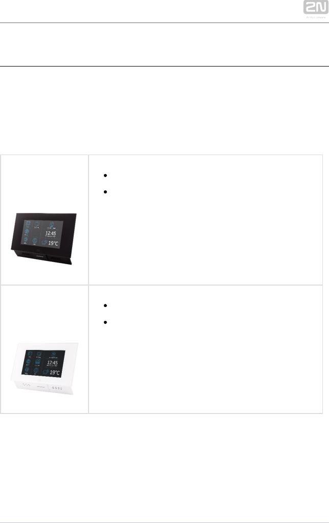
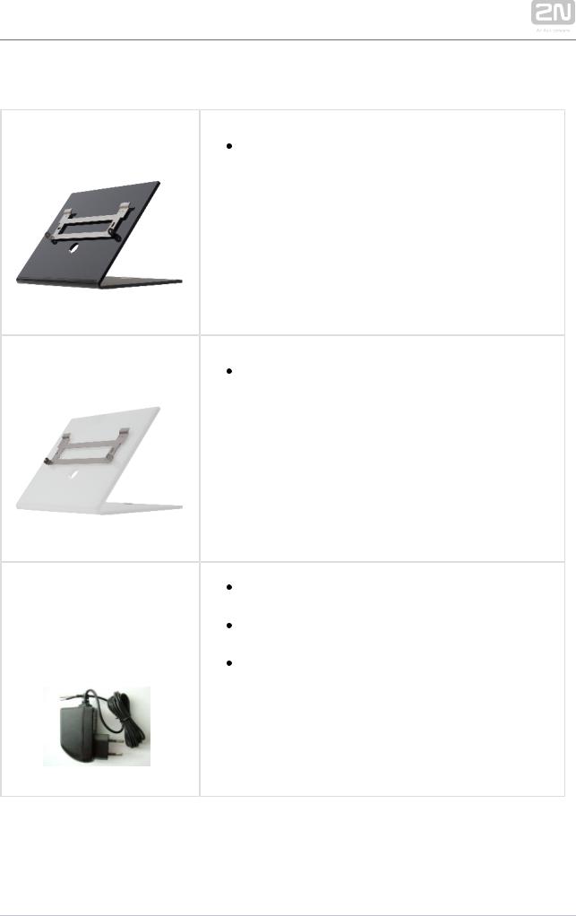
91378382, 01425-001
Part No.:
91378382W, 01426-001
Part Nos.: 91378381E
91378381GB
91378381US
2N®Indoor Touch desk stand black
2N®Indoor Touch desk stand white
Stabilised 12 V / 0,75 A source to be used where PoE supply is unavailable.
The part numbers differ in their electric socket markings (E/GB/US).
The exclusive type of power adapter SYS1561-0912 to
be used with all 2N®Indoor Touch 2.0 devices.
2N TELEKOMUNIKACE a.s., www.2n.cz |
9/135 |

Licence
Part No. |
Description |
91378395 HTTP API – the licence unlocks the HTTP API functions
2N TELEKOMUNIKACE a.s., www.2n.cz |
10/135 |
1.3 Terms and Symbols
The following symbols and pictograms are used in the manual:
Safety
 Always abide by this information to prevent persons from injury.
Warning
 Always abide by this information to prevent damage to the device.
Caution
 Important information for system functionality.
Tip
 Useful information for quick and efficient functionality.
Note
 Routines or advice for efficient use of the device.
2N TELEKOMUNIKACE a.s., www.2n.cz |
11/135 |

1.4 Safety Precautions
The manufacturer reserves the right to modify the product in order to improve its qualities. The manufacturer continuously responds to the clients' requirements by
improving the software. Refer to the www.2n.cz company websites for the latest 2N®
Indoor Touch 2.0 firmware and User Manual.
 It is prohibited to use any transmitters, including 2N®Indoor Touch 2.0 with an
internal WiFi adapter, in areas where explosives are used, such as quarries.
 WiFi adapters may affect sensitive life-saving devices in medical centres. Therefore, it is prohibited to use device with an internal WiFi adapter in such facilities.
 In general, any RF energy radiation prohibition regarding WiFi antenna equipped devices applies to device with an internal WiFi adapter.
 Where necessary, a device unit can be installed at a safe distance from the prohibited area and an Ethernet cable can only be carried to the required site.
 Although the device is not intended for cars or aeroplanes, all prohibitions and regulations relating to adapter equipped devices apply to device too.
2N TELEKOMUNIKACE a.s., www.2n.cz |
12/135 |

2. Description and Installation
This section describes the 2N®Indoor Touch 2.0 installation and correct connection.
Here is what you can find in this section:
 2.1 Before You Start
 2.2 Brief Installation Guide
 2.3 Installation Conditions
 2.4 Status LED
 2.5 First Startup
The device is designed solely for wall mounting. Install the device with the aid of a holder, which is included in the product and Installation Manual delivery.
Prepare the proper wall fittings (screws and wall plugs suitable for the given wall type and structure). Respect the local standards for installation of electronic devices onto flammable materials while mounting!
Use a cross-point screwdriver for tightening the fitting screws on the device sides to
place 2N®Indoor Touch 2.0 properly.
2N TELEKOMUNIKACE a.s., www.2n.cz |
13/135 |
2.1 Before You Start
Product Completeness Check
Please check the 2N®Indoor Touch 2.0 delivery before starting installation:
1 |
2N®Indoor Touch 2.0 |
1 Quick Start manual
1 Wall holder (screwed to device)
1 Installation fittings (2 screws, 2 plugs for flush mounting)
1 Microfiber screen cleaning cloth
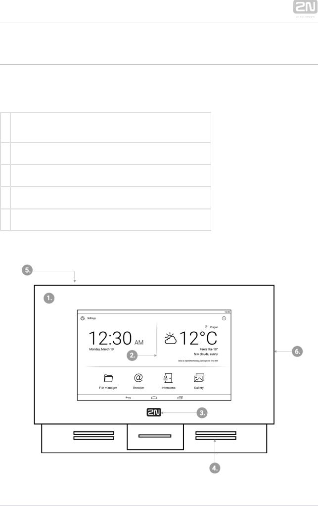
Front Layout
2N TELEKOMUNIKACE a.s., www.2n.cz |
14/135 |

1.Glass frame
2.LCD display with capacitive touch layer
3.Status RGB LED
4.Loudspeaker
5.Microphone
6.Micro SD card slot
Backside Connectors
2N TELEKOMUNIKACE a.s., www.2n.cz |
15/135 |
1.RJ-45 LAN 10/100BaseT connector
2.12 V / 0,75 A DC supply terminal board (only if PoE is not used)
3.Restart/Factory reset button
4.Binary input/output terminal board (for application control)
5.Micro SD card slot
6.Logic inputs and outputs
Tip
 External doorbell button or Relay connection guides are available at faq. 2n.cz.
Warning
 Do not remove the backside rubber sealing as it improves the accoustic properties of the product during wall mounting.
2N TELEKOMUNIKACE a.s., www.2n.cz |
16/135 |
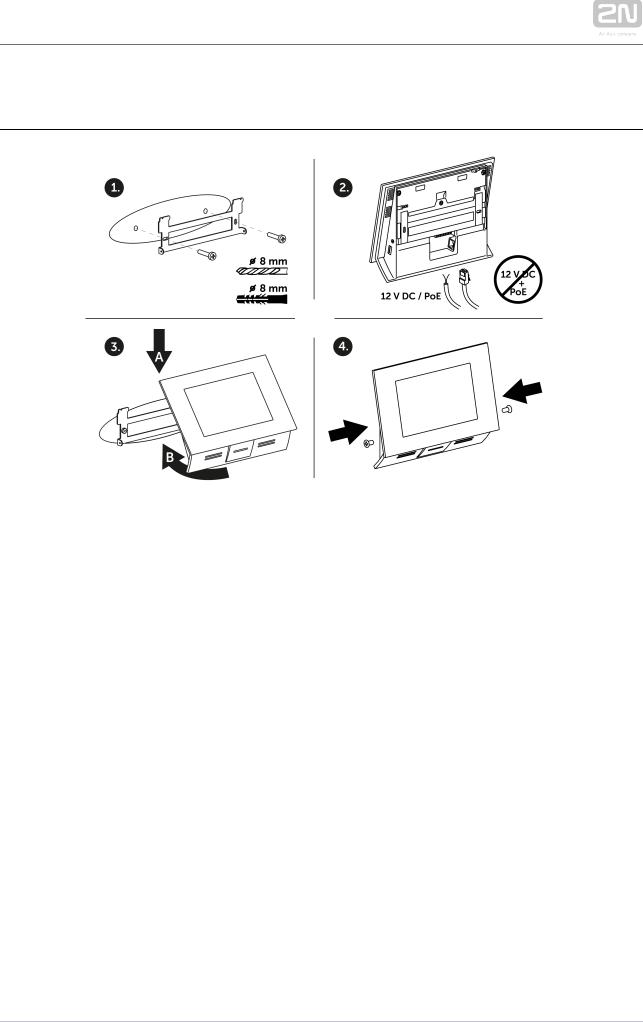
2.2 Brief Installation Guide
1.Install the device holder onto a vertical wall. The recommended installation height is 120 cm above the floor. The product package includes screws and plugs for mounting into classic bricks. Use appropriate installation fittings for a different type of wall material!
2.Feed the device via an Ethernet PoE adapter (or PoE supporting Ethernet switch /router) or a 12 V / 0,75 A DC power adapter.
a.With PoE supply, just snap RJ-45 into the appropriate connector.
b.With 12 V DC 0,75 A supply, screw the power adapter plus and minus cables into the appropriate terminal board on the device.
c.Simultaneous PoE + 12 V / 0,75 A DC supply is not recommended!
3.Put the device on the holder as follows:
a.Place the device carefully from top to bottom with its bottom part slightly away (up to 5 cm) from the wall.
b.When the device fits to the main holder supports, push the device bottom part onto the wall.
4.Tighten the safety screws on both the device sides.
2N TELEKOMUNIKACE a.s., www.2n.cz |
17/135 |

2.3 Installation Conditions
Make sure that the following 2N®Indoor Touch 2.0 installation conditions are met:
 There must be enough space for device installation.
 Device is designed for vertical wall mounting (perpendicular to the floor) in the height of up to 120 cm above the floor. If necessary, operate device in a position other than as aforementioned for a short time only, for quick testing purposes in a servicing centre, for example.
 Exceeding the allowed operating temperature may not affect the device immediately but leads to premature ageing and lower reliability. Refer to 6. Technical Parameters for the acceptable range of operating temperatures and relative humidity values.
 Device is not designed for environments with increased vibrations such as means of transport, machine rooms and so on.
 Device is not intended for dusty environments and places with unstable humidity and abrupt temperature changes.
 Device may not be exposed to aggressive gas, acid vapours, solvents, etc.
 Device is not intended for direct connection into the Ethernet/Internet.
 Device must be connected to the Ethernet/Internet via a separating active network element (switch/router).
 Device is designed for indoor use. It may not be exposed to rain, flowing water, condensing moisture, fog, etc.
 Device cannot be operated on places exposed to direct sunshine and near heat sources.
 Keep some free space above and below device to allow air to flow and conduct heat away.
 No strong electromagnetic radiance is allowed on the installation site.
 The VoIP connection must be configured properly according to the SIP and other VoIP recommendations.
 It is recommended that the power adapter be connected to the mains via a UPS and reliable overvoltage protection.
Wall Mounting
2N®Indoor Touch 2.0 is designed for wall mounting. Follow the steps below:
1.Unscrew the holder-fitting screws on the device sides.
2.Turn the metal holder slightly aside in the upper part of the device.
3.Move the holder downwards.
4.Fit the loose holder to the wall on the installation site.
2N TELEKOMUNIKACE a.s., www.2n.cz |
18/135 |
5. Put the device on the holder and tighten the safety screws. Follow the installation instructions printed on the device package.
Power Supply Connection
You can feed 2N®Indoor Touch 2.0 as follows:
1.Use 12 V / 0,75 A DC power adapter (order no. 91378381E/91378381GB /91378381US)connected to the terminal board (see the figure).
2.Use an Ethernet cable connected to a PoE supply or PoE supporting Ethernet switch/router.
A successful operation is indicated by a status RGB LED or LCD display.
PoE Supply Connection
Use a standard straight RJ-45 terminated cable to connect device to the Ethernet. The device supports the 10BaseT and 100BaseT protocols. The Ethernet connection state is indicated by the LEDs placed on the RJ-45 connector. Refer to 3.3 Device Configuration for the factory settings of the device Ethernet interface.
Caution
 Factory reset results in a change of the Ethernet interface configuration!
 A defective Ethernet cable may lead to a high packet loss in the Ethernet and subsequent instability and poor video call quality!
Warning
 Connection of a defective or improper power adapter may lead to a temporary or permanent failure of the 2N®Indoor Touch 2.0 unit!
2N TELEKOMUNIKACE a.s., www.2n.cz |
19/135 |

Ethernet cable connector |
Ethernet port |
Licence Limitations
2N®Indoor Touch 2.0 can contain time-limited software licences. Refer to 3.3 Device
Configuration for details.
Firmware Upgrade
We recommend you to upgrade the device firmware during installation. Refer to www. 2n.cz for the latest FW version. Refer to 3.4. Device Upgrade for the firmware upgrade procedure.
2N TELEKOMUNIKACE a.s., www.2n.cz |
20/135 |
2.4 Status LED
Status LED indicates the device states when the LCD display is switched off or the device is in the service mode. See the table below for the LED colours and states:
Device Startup:
Colour |
State |
Blue is on |
Device initialisation |
Red is on |
First boot phase |
Green is on |
Operating system start |
Yelow is on |
Factory setting initialisation |
Blue is flashing |
Factory reset |
Purple is flashing |
System upgrade process |
No light |
Device state is displayed |
Standard Operation:
Colour State
No light |
Device state is displayed |
|
|
|
Blue is on |
Stand-by mode (display off) |
|
|
|
Other |
Notification of other states of applications running in the system (2N |
® |
IP Mobile, e. |
|
states |
||||
|
|
|||
|
g.). |
|
|
2N TELEKOMUNIKACE a.s., www.2n.cz |
21/135 |
2.5 First Startup
When you start the device for the first time, the initial initialisation (longer start) is performed and indicated by the following LED notification sequence: Red Blue Green Boot animation on the screen Introductory system screen.
The introductory screen provides essential information for User Manual saving
/reading. Select "Don't show welcome screen and run 2N® IP Mobile at next start
instead" to deactivate this screen for future system startups.
Caution
 If you do not select the "Don't show welcome screen and run 2N® IP
Mobile at next start instead" option on the welcome screen before quitting and then enable the 2N® IP Mobile launch after the system
startup in the Launcher configuration, the application will not be started for technical reasons. Therefore, be sure to disable the welcome screen
start to make 2N®IP Mobile run automatically after the system startup.
The table below shows the factory values of relevant device parameters:
Parameter |
Value |
IP address |
will be assigned by the DHCP server |
IP mask |
will be assigned by the DHCP server |
IP gateway |
will be assigned by the DHCP server |
Access password to configuration |
2n |
Administrator password |
2n |
Time/weather location |
Prague, CZ |
Stand-by switching time |
1 minute |
SW licence |
Basic unlimited licence |
2N TELEKOMUNIKACE a.s., www.2n.cz |
22/135 |

Parameter |
Value |
|
(or according to the Part No.) |
Caution
 Change the access password while configuring the device for the first time to avoid unauthorised access to configuration!
System Licence
2N®Indoor Touch 2.0 has a factory licence key, which can be time-limited (depending
on the Part No.). The licence expiry may cause a partial limitation of the device functionality! Refer to 3.3 Device Settings for the current licence state and licence adding procedure if necessary.
2N TELEKOMUNIKACE a.s., www.2n.cz |
23/135 |

3. 2N® Indoor Touch 2.0
Configuration
This section describes the 2N®Indoor Touch 2.0 configuration.
Here is what you can find in this section:
 3.1 Factory Reset
 3.2 Home Screen
 3.3 Device Configuration
 3.4 Device Upgrade
2N TELEKOMUNIKACE a.s., www.2n.cz |
24/135 |
3.1 Factory Reset
Follow the steps below to reset the 2N®Indoor Touch 2.0 factory values:
1.Press the Factory Data Reset button in Settings / Administrator mode – ON / Backup & reset.
2.Press and hold the Reset button on the device backside:
a.Remove the device from the installation holder.
b.Press and hold the Reset button until the notification RGB LED lights up (yellow, approx. 10 seconds).
c.Release the Reset button and follow the instructions displayed.
Caution
 You can reset the factory values only if the administrator mode is on.
 Factory reset results in a complete deletion of all user data.
2N TELEKOMUNIKACE a.s., www.2n.cz |
25/135 |

3.2 Home Screen
The Home Screen is divided into three subsections: Current time and date, Weather widget and five configurable application positions. The Setting and Information buttons are also available here.
Factory settings:
 Time/Date tiles
 Weather tile
 File Manager – standard file system application
 Browser – Internet browser application
 Intercoms – application responsible for communication of the 2N IP intercoms with other answering units
 Gallery – photo/image processing application
2N TELEKOMUNIKACE a.s., www.2n.cz |
26/135 |
The lower graphic bar includes five graphic controls:
 Back icon (triangle) – return one level higher or one step back (depending on the application type).
 Home icon (circle) – return to the introductory screen.
 Square icon – switch the currently launched applications.
 Speaker icons – increase/decrease the system loudspeaker volume.
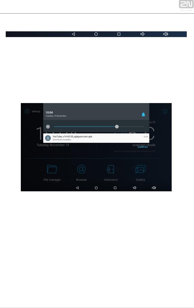
Notification Bar
The notification bar provides a list of missed events and notifications allowing you to set the DND mode and display brightness level instantly. Swipe your finger in a straight downward line from the upper edge of the screen to pull down the notification bar. Click the Delete all icon to remove the notification list.
2N TELEKOMUNIKACE a.s., www.2n.cz |
27/135 |
3.3 Device Configuration
Click the Settings button on the introductory page to access the configuration section. Complete the correct access password.
Caution
 The factory access password is "2n“. If you lose the access data, you will have to factory reset the device! Change the password in the Settings / Personal / Language & input.
 Administrator mode – configure advanced functions.
The device configuration consists of five sections: Device, Wireless & Networks, 2N® IP Mobile, Personal, System; each section is divided into subsections, see below.
 3.3.1 User Settings
 3.3.2 Administrator Settings
 3.3.3 Intercoms
2N TELEKOMUNIKACE a.s., www.2n.cz |
28/135 |

3.3.1 User Settings
This subsection describes the settings that can be accessed without the administrator password. The subsection contains the following parts:
 3.3.1.1 Device
 3.3.1.2 Personal
 3.3.1.3 System
2N TELEKOMUNIKACE a.s., www.2n.cz |
29/135 |
3.3.1.1 Device
This section helps you set the first menu level and quick navigation parameters (click any subsection) into selected device configuration sections.
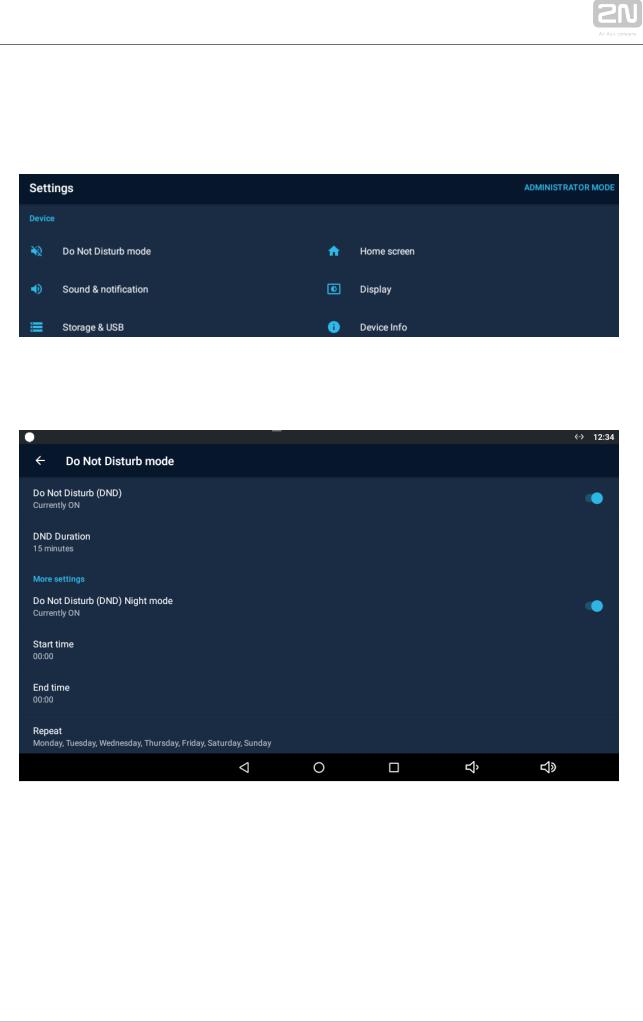
Do Not Disturb Mode
 Do Not Disturb (DND) – disable any notification while DND is active. While activating DND you can set any interval in the range between 15 minutes and 24 hours, or permanently.
 Do Not Disturb (DND) Night mode – disable any notification while DND is active. Set this mode for each weekday with repetition and specify the start and end time.
 Start time – set the beginning of the DND Night mode time validity.
 End time – set the end of the DND Night mode time validity.
2N TELEKOMUNIKACE a.s., www.2n.cz |
30/135 |
Loading...