


Dear customer,
Let us congratulate you on having purchased the SmartGate system. This new product has been developed and manufactured to provide the maximum utility value, quality and reliability. We hope you will be fully satisfied with this GSM gateway for a long time. Therefore, use your SmartGate for purposes it has been designed and manufactured for, in accordance herewith.
The manufacturer reserves the right to modify the product in order to improve its qualities.
Safety Precautions
Do not switch on SmartGate in the vicinity of medical apparatuses to avoid interference. The minimum distance of the antenna and pacemakers should be 0,5 m.
Do not switch on SmartGate aboard of a plane.
Do not switch on SmartGate near petrol stations, chemical facilities or sites where explosives are used.
Any mobile telephone use prohibition based on RF energy radiation applies to SmartGate too.
SmartGate may disturb the function of TV sets, radio sets and PCs.
Warning! SmartGate contains components that can be swallowed by small children (SIM card, antenna, etc.).
The voltage value mentioned on the power adapter may not be exceeded. If you connect SmartGate to another power supply, make sure that the voltage value is in the acceptable range.
When your SmartGate comes to the end of its operational life, dispose of it in accordance with applicable regulations.

User Manual Versions
Version Amendments to Earlier Versions
1.00∙ The User Manual applies to SmartGate FW Version 1.00A.
Upgrade
The manufacturer continuously meets customer requirements by improving the firmware. For the latest SmartGate processor firmware, programming tool and User
Manual see www.2n.cz. For a detailed description of the SmartGate firmware upgrade refer to the section devoted to the PC programming tool.

Packing List
SmartGate delivery contains the following items:
Item |
Number of |
|
Pieces |
||
|
||
SmartGate |
1 pc |
|
|
|
|
Antenna for direct connection |
1 pc 1) |
|
Magnetic Antenna with coax cable |
1 pc 1) |
|
Supply adapter |
1 pc |
|
|
|
|
Telephone cable |
2 pc |
|
|
|
|
PC-connection serial cable |
1 pc |
|
|
|
|
SMS sending input connector |
1 pc |
|
|
|
|
Dowels |
2 pcs |
|
|
|
|
Screws |
2 pc |
|
|
|
|
CD-ROM with User Manual and software |
1 pc 2) |
|
Quick Installation Guide + mounting pattern |
1 pc |
|
|
|
|
Warranty certificate |
1 pc |
|
|
|
Notes:
1)The delivery includes an antenna to be connected directly to the SmartGate SMA connector. An antenna with a cable should be used when GSM signal is poor or in case of interference with other devices.
2)Enclosed software:
∙SmartGate PCManager for parameters programming.
∙SmartGate SMSgateway for easy SMS sending and receiving.
∙SmartGate Driver for PC.
∙User Manual in pdf format.
∙Lists of AT Commands for SIEMENS GSM modules.

CONTENTS
1. |
SMARTGATE PURPOSE .................................................................................................... |
1 |
|
|
1.1. |
BASIC FUNCTIONS ...................................................................................................................... |
1 |
|
1.2. ADVANTAGES OF SMARTGATE USE ............................................................................................. |
1 |
|
2. |
INSTALLATION ................................................................................................................... |
2 |
|
|
2.1. |
PROPER LOCATION .................................................................................................................... |
2 |
|
2.2. |
EXTERNAL ANTENNA CONNECTION.............................................................................................. |
3 |
|
2.3. |
SIM CARD INSTALLATION............................................................................................................ |
3 |
|
2.4. |
CONNECTOR DESCRIPTION ......................................................................................................... |
4 |
|
2.5. |
TELEPHONE LINES CONNECTION ................................................................................................. |
4 |
|
2.6. |
POWER SUPPLY CONNECTION .................................................................................................... |
5 |
|
2.7. |
SMS SENDING INPUT CONNECTION ............................................................................................ |
5 |
|
2.8. |
PC CONNECTION ....................................................................................................................... |
5 |
3. |
SMARTGATE STATUS INDICATION.................................................................................. |
6 |
|
|
3.1. |
INDICATION LEDS....................................................................................................................... |
6 |
|
3.2. |
TELEPHONE LINE TONES ............................................................................................................ |
7 |
4. |
SIM CARD PIN PROTECTION ............................................................................................ |
8 |
|
|
4.1. |
PIN ENTERING BY PCMANAGER ................................................................................................. |
8 |
|
4.2. |
PIN ENTERING VIA TELEPHONE LINE ........................................................................................... |
8 |
|
4.3. |
AUTOMATIC PIN ENTERING......................................................................................................... |
9 |
5. |
VOICE FUNCTION............................................................................................................. |
10 |
|
|
5.1. |
DIALTHRU GATEWAY ................................................................................................................ |
10 |
|
5.2. GATEWAY FOR EXTENSION LINE OF PBX.................................................................................... |
12 |
|
|
5.3. GATEWAY FOR TRUNK LINE OF PBX........................................................................................... |
13 |
|
6. |
SMS SENDING INPUT....................................................................................................... |
14 |
|
7. |
COM – SERIAL INTERFACE............................................................................................. |
15 |
|
|
7.1. PROGRAMMING, MONITORING ................................................................................................... |
15 |
|
|
7.2. |
CSD PC-PC DATA TRANSMISSION ........................................................................................... |
15 |
|
7.3. |
FAX TRANSMISSION - PC-FAX................................................................................................. |
16 |
|
7.4. CSD OR HIGH-SPEED GPRS DATA CONNECTION TO INTERNET.................................................. |
16 |
|
|
7.5. |
SMS SENDING AND RECEIVING................................................................................................. |
16 |
|
7.6. COMBINATION OF COM TRAFFIC WITH VOICE CALLS .................................................................. |
17 |
|
|
7.7. |
LIST OF SUPPORTED AT COMMANDS......................................................................................... |
17 |
8. |
SMARTGATE PARAMETER PROGRAMMING ................................................................ |
18 |
|
|
8.1. |
PC BASED PROGRAMMING........................................................................................................ |
18 |
|
8.2. |
PARAMETER TABLES ................................................................................................................ |
21 |
9. |
TROUBLESHOOTING ....................................................................................................... |
39 |
|
10. LIST OF ABBREVIATIONS ............................................................................................... |
40 |
||
11. TECHNICAL PARAMETERS............................................................................................. |
41 |
||

1. SmartGate purpose
1.1. Basic Functions
∙The primary purpose of SmartGate is to transmit voice between GSM network and attached phone terminals. You can connect terminal with FXO interface (trunk line of PBX, phone set, answering machine etc.) to FXS interface on SmartGate
(connector with phone icon) and terminal with FXS interface (extension line of PBX) to FXO interface on SmartGate (connector with crossed out phone icon).
∙You can establish data connections (GPRS, CSD), fax connections (PC-FAX only) and send/receive SMS using SmartGate in combination with a PC and appropriate software.
∙You can send an SMS to a pre-programmed number using the SMS sending input.
1.2. Advantages of SmartGate Use
∙Call cost cutting – the calls are routed to GSM or analog network according to their number prefix. Route all GSM calls from PBX to SmartGate to save a lot on PSTN – GSM calls.
∙Easy installation – you can easy program SmartGate as you need with enclosed SW.
∙You get all you need in the delivery – your SmartGate delivery contains all you need to operate the system (the power supply adapter, telephone cables, PC serial cable, SMS input connector, CD-ROM with software).
∙Solution for sites without telephone lines – such as mountain chalets, exhibitions, conferences, etc.
∙DialThru technology – all your calls will be routed most cost-effective way.
∙Follow-me function – you newer miss an incoming call from analog network. Incoming call will ring on connected phone and on your mobile phone too.
∙CLIP - SmartGate is equipped with the FSK-based CLIP feature, so if a terminal capable of receiving the CLIP is used you know the caller‘s number.
∙Quick data connection – SmartGate transmits data using the high-speed GPRS connection (GPRS class 10, max. 85.6 kbps).
∙SMS sending input – simply send an SMS to a pre-programmed number by closing the contact. Recommended for easy supervision, simple securing, etc.
∙Radiation hazard minimization – you are not exposed to a direct effect of the antenna RF electromagnetic field while telephoning as opposed to mobile telephones.
∙Full GSM coverage - SmartGate is available as tri-band for European markets (900, 1800 and 1900MHz), and as tri-band for the American market (850, 1800 and
1900MHz).
1
2. Installation
2.1. Proper Location
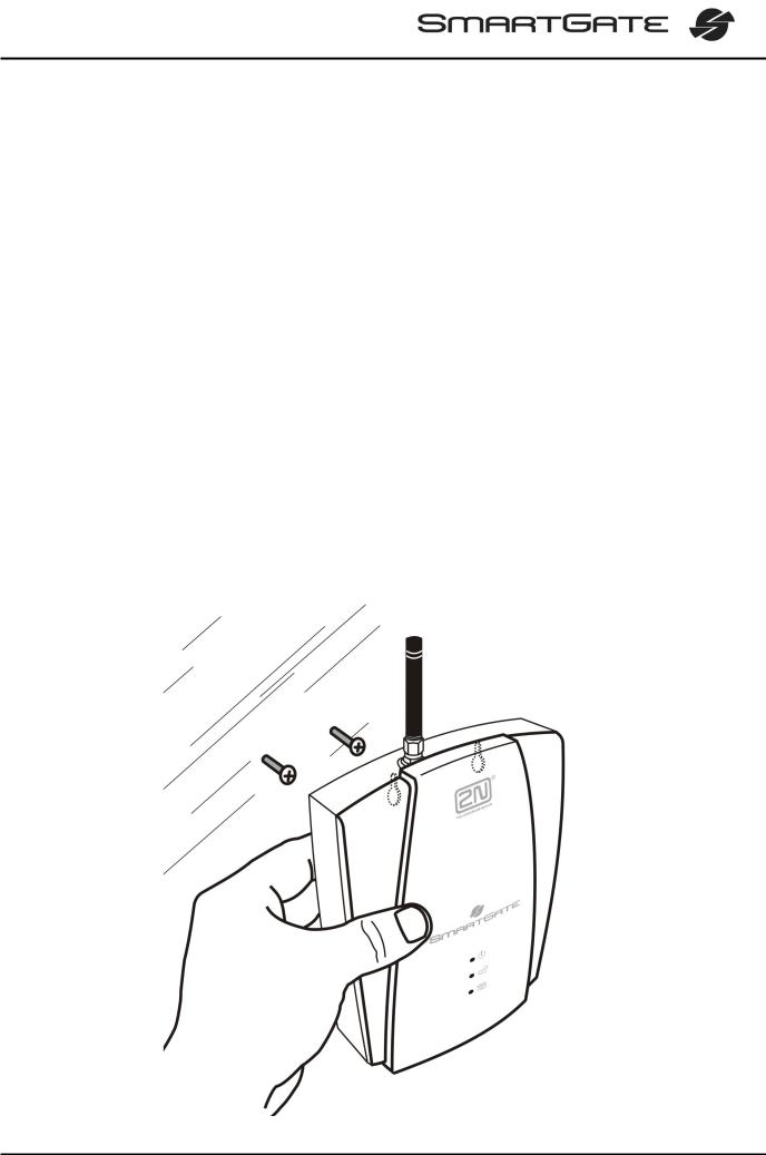
∙SmartGate is designed for vertical mounting on suspension holes (use the mounting pattern). This position is the best for signal reception because a vertical antenna is used. SmartGate can be operated in the horizontal position too where the GSM signal is good or with antenna connected on coax cable.
∙Install SmartGate with respect to the GSM signal strength – check the signal strength using the PCManager.
∙Place SmartGate out of range of sensitive devices and human bodies for electromagnetic interference reasons.
∙SmartGate can disturb other telecommunication systems. Place phone lines and connected terminals and PBX’s faraway from antenna.
∙For the allowed range of operating temperatures refer to the “Technical
Parameters”.
∙It is impossible to operate SmartGate on sites exposed to direct solar radiation or near heat sources.
∙SmartGate is designed for indoor use. It may not be exposed to rain, flowing water, condensed moisture, fog, etc.
∙SmartGate may not be exposed to aggressive gas, acid vapours, solvents, etc.
∙SmartGate is not designed for environments with high vibrations such as means of transport, machine rooms, etc.
2
2.2. External Antenna Connection
Screw the antenna enclosed into the SMA antenna connector. Tighten the antenna connector gently with your hand - never use spanner!
The antenna for direct connection has a sufficient gain for trouble-free operation in normal conditions. If the GSM signal is poor, in case of voice disturbance, or if you want to place your antenna separately from SmartGate, you can use an antenna with an SMA-connector terminated coax cable. The antenna should be mounted vertically.
For antenna and cable parameters see the “Technical Parameters“.
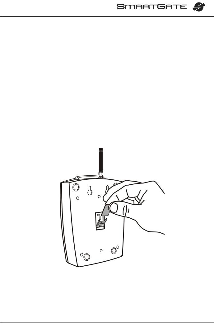
2.3. SIM Card Installation
Open the SIM card holder on SmartGate’s backside, insert the SIM card and close it properly. Select the required GSM provider and SIM card services, such as call forwarding, call barring, preferred networks, SMS service centre, etc. in your mobile phone before inserting your SIM card in SmartGate.
3
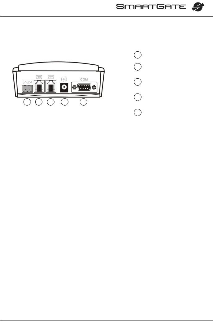
2.4. Connector description
|
|
|
|
1 |
SMS sending input |
|
|
|
|
2 |
Telephone line – interface FXO |
|
|
|
|
|
RJ 11, 6/2 |
|
|
|
|
3 |
Telephone line – interface FXS |
|
|
|
|
|
RJ 11, 6/2 |
|
|
|
|
4 |
Power supply connector |
1 |
2 |
3 |
4 |
5 |
DC Jack 5,5/2,1mm |
5 |
RS232C serial line |
|
D-Sub 9 pins |
||
|
2.5. Telephone Lines Connection
2.5.1. DialThru gateway – basic connection
Phone set is normally connected to extension line of PBX. Wire up SmartGate between phone set and PBX. Link extension line of PBX to FXO interface and phone set to FXS interface on SmartGate.
2.5.2. Gateway for extension line of PBX
Link free extension line of your PBX to FXO interface on SmartGate. FXS interface remains unconnected.
2.5.3. Gateway for trunk line of PBX
Link free trunk line of your PBX to FXS interface on SmartGate. Program PBX to route all GSM calls to SmartGate. Incoming calls from GSM network will be routed to
PBX.
You can connect a standard telephone, answering machine or any other FXO-interface terminal to SmartGate. Outgoing calls from phone will be routed to GSM network, incoming calls from GSM will ring on the phone.
SmartGate is equipped with the FSK-based CLIP and so it is advantageous to connect a terminal that is able to display or process the CLI. You must activate the function on SmartGate.
2.5.4. Gateway for both, trunk and extension, lines of PBX
SmartGate is very flexible thanks to his three routing tables. You can connect trunk and extension lines of one PBX to proper connectors on SmartGate. You can program the complex as follows: outgoing calls from PBX will be routed through trunk line to GSM network. Incoming calls from GSM will be routed to extension line of PBX. This configuration is suitable for PBX’s with no capability of dial-in on trunk lines.
4

2.6. Power Supply Connection
SmartGate is powered with 10-16V DC. Where a source other than the included power supply adapter is used, the voltage range and polarity shown on the SmartGate power supply connector have to be maintained. For backup power supply you can use
EnergyBank – backup source with accumulators.
Do not power on the supply until the antenna is connected to SmartGate to avoid the
GSM module damage.
2.7. SMS Sending Input Connection
You have got a special connector for easy connection to SmartGate. The connector is equipped with screwing clamps to connect wires from a switching contact (device to be monitored). The other connector end can be connected to the respective SmartGate panel connector.
The input is designed for the contact of relay connected between the input pins. The input is activated by contact closing (pin interconnection).
A transistor switch or logic signal can be used too. The pin near the telephone line connector is connected to GND of the device the second one is active. Please, respect the loop current polarity. There is over-voltage protection up to +12V DC there.
2.8. PC Connection
You have got a serial cable for PC connection. It is a modem cable where all of the 9 pins are 1:1 interconnected – in case you want to use another cable.
If you use a longer cable, make sure it works properly. There may occur errors at higher transmission rates.
5
3. SmartGate Status Indication
3.1. Indication LEDs
Name |
Meaning |
|
|
|
|
|
|
|
Power supply |
∙ Light = SmartGate is powered. |
|
∙ Flashes once in 2s = HW error, contact the manufacturer. |
||
|
||
|
|
|
|
∙ Light = registered into GSM network |
|
|
∙ Flashes once in 1s = not registered, SIM card inserted |
|
|
∙ Flashes once in 3s = not registered, SIM card not inserted |
|
GSM network |
∙ Flashes 4 times quickly = enter your PIN |
|
|
∙ Flashes 8 times quickly = enter your PUK |
|
|
∙ Flashes quickly continuously = all functions are blocked. |
|
|
Your SIM doesn’t correspond to the GSM operator lock |
|
|
|
|
|
∙ No light = standby |
Orange for FXS interface:
∙Flashes quickly = line off-hook or ringing
∙Light = call FXS – GSM
Telephone line ∙ Flashes once in 3s = data connection in progress
Green for FXO interface:
∙Flashes quickly = line off-hook or ringing
∙Light = call FXO – GSM
Alternately orange and green:
∙Quickly = ringing from FXO is connected to FXS interface
∙Slowly = call FXS – FXO
6
3.2. Telephone Line Tones
3.2.1. Status Tones
The GSM gateway sends tones to the telephone line to indicate the line status. The tone frequency is 425 Hz in initial setting. Frequency is programmable; it is possible to set up double frequency tones.
Dial tone: Continuous tone, or 

 (morse A) according to setting
∙SmartGate is ready to receive dialing.
Ringing tone: 
∙The called subscriber's telephone is ringing.
∙The GSM network or connected PBX transmits this tone.
Busy tone: 


 , programmable cadency
∙In case of call routing to GSM network SmartGate generate busy tone in any of the following cases:
§The SIM card has not been installed.
§SmartGate is not registered to GSM network.
§SmartGate is registered into a foreign network but roaming is disabled.
§The called subscriber line is busy.
§The called subscriber hangs up (disconnection).
§The called number has too many digits (more than 30).
§The called number is barred.
∙In case of call routing to SmartGate’s FXO interface SmartGate generate busy tone in any of the following cases:
§Line is not connected. There is no current on the line.
§The called number has too many digits (more than 30).
§The called number is barred.
§If the called subscriber line is busy or called subscriber hangs up, busy tone is generated by PBX.
Dialing end signaling: 
∙Dialing reception has been terminated. Connection is being established.
PIN tone: 


∙Enter the PIN code.
∙This tone is transmitted upon power up if the PIN has to be entered manually.
PUK tone: 


∙Enter the PUK code.
∙This tone is transmitted upon repeated wrong PIN entering attempts. SIM card is blocked.
7
4. SIM Card PIN protection
If a SIM card is PIN-protected and the PIN is not programmed in SmartGate, GSM
LED indicates the state and the PIN tone is transmitted on telephone line.
4.1. PIN Entering by PCManager
Like other parameters, the PIN code can be entered using a PC programming tool. The PIN will be entered automatically upon every SmartGate power up.
4.2. PIN Entering via Telephone Line
PIN entering via a telephone line connected to FXS interface:
1.Hook off the phone, you can hear the PIN tone.
2.Enter the PIN using the DTMF. You can cancel the wrong PIN by entering of a
|
, or you can hang up before sending a . |
3. |
To confirm enter a . |
4. |
If you hear the busy tone in a while (a few seconds), you have entered the PIN |
|
correctly. Hang up and wait for registering to the GSM network. |
5. |
If you hear the PIN tone again in a while, you have entered a wrong PIN. Re- |
|
enter the PIN correctly. |
6. |
If you hear the PUK tone in a while, you have entered a wrong PIN and the |
|
SIM card is blocked. Use the mobile phone to unblock the SIM card. |
PIN entering via a telephone line connected to FXO interface if SmartGate is used as gateway for extension line of PBX:
1.Dial the SmartGate’s extension number on your PBX. SmartGate detects ringing and after off hook generates the PIN tone.
2.Enter the PIN using the DTMF. You can cancel the wrong PIN by entering of a
|
, or you can hang up before sending a . |
3. |
To confirm enter a . |
4. |
If SmartGate after a while (a few seconds) hangs up, you have entered the |
|
PIN correctly. |
5. |
If you hear the PIN tone again in a while, you have entered a wrong PIN. Re- |
|
enter the PIN correctly. |
6. |
If you hear the PUK tone in a while, you have entered a wrong PIN and the |
|
SIM card is blocked. Use the mobile phone to unblock the SIM card. |
A correctly entered PIN is stored in SmartGate’s memory as if you had programmed it using the PCManager. The PIN will be entered automatically upon every SmartGate power up.
8

4.3. Automatic PIN Entering
You need not enter the PIN upon power up if it is stored in SmartGate – it is entered automatically. This function is useful in case of power failure; SmartGate is operable in a short time after power recovery without any intervention by the operating staff.
Caution! One PIN entering option is exhausted by the attempt to enter the PIN automatically upon SIM card or PIN change. If wrong, the automatically entered PIN is cleared from the internal memory to avoid another false attempt upon next power on. There are still two manual PIN-entering attempts after such unsuccessful automatic entering. To prevent the unsuccessful automatic PIN entering, delete or program properly the SmartGate PIN using the PCManager in the case of SIM card change.
9

5. Voice function
Outgoing and incoming call establishing procedures is for illustration described for analog phone connected to FXS interface and extension line of PBX connected to FXO interface on SmartGate. In case of other equipment connection, please check SmartGate’s function by connecting a phone.
Suppose that a SIM card has been inserted, the PIN code entered or not required, the antenna connected and SmartGate registered to GSM network – the GSM network
LED is permanently on and you can hear the dial tone upon line off-hook.
5.1. DialThru gateway
Extension line of PBX is connected to FXO interface and phone is connected to FXS interface on SmartGate.
5.1.1. Outgoing call on FXS interface
1.Hook off the telephone, you can hear the dial tone and the Line LED starts flashing.
2.Dial the required subscriber number. SmartGate receives tone dialing (DTMF) by default. If your telephone transmits pulse dialing only, program SmartGate to receive pulse dialing. The delay between dialed digits may not exceed 5 s
(programmable parameter). The number is evaluated as complete after this timeout.
3.A short delay follows the last-dialed digit for SmartGate to await further dialing. Then, the dialing end is signaled and connection is established.
4.Prefix of dialed number is compared with filled rows of FXS routing table. The call is rejected, routed to GSM network or to FXO interface according to the routing table.
5.If the called subscriber is available, you can hear the ringing tone. If not, you can hear the busy tone or any of the GSM provider’s messages.
6.When the called subscriber answers the call, a call is established. The Line LED is permanently on during the call (Orange for calls to GSM. Green-Orange alternate for FXS-FXO calls).
7.Hang up to terminate the call. The Line LED goes off. If the called subscriber hangs up first, you can hear the busy tone.
5.1.2. Incoming call from GSM network
1.The CLI is compared with filled rows of GSM routing table. The call is rejected, routed to FXS interface – connected phone, or to FXO interface according to the routing table. Routing to FXO interface isn’t usually used in case of DialThru gateway.
2.Ringing on FXS interface signals incoming call. The Line LED flashes during ringing. If programmed so, SmartGate transmits the CLIP by FSK between the first and second rings. Advanced telephone sets are able to display the CLI.
3.Hook off the phone to establish the call. The Line LED is permanently on during the call.
4.Hang up to terminate the call. The Line LED goes off. If the called subscriber hangs up first, you can hear the busy tone.
10
 Loading...