

Page 1

www.2n.czVersion
Firmware
2N
®
Lift8
Communicator for lifts
User manual
1.6.0
1.6.0
Page 2

The 2N TELEKOMUNIKACE a.s. is a Czech manufacturer and supplier of telecommunications
equipment.
The product family developed by 2N TELEKOMUNIKACE a.s. includes GSM gateways, private
branch exchanges (PBX), and door and lift communicators. 2N TELEKOMUNIKACE a.s. has
been ranked among the Czech top companies for years and represented a symbol of
stability and prosperity on the telecommunications market for almost two decades. At
present, we export our products into over 120 countries worldwide and have exclusive
distributors on all continents.
2N is a registered trademark of 2N TELEKOMUNIKACE a.s. Any product and/or other
®
names mentioned herein are registered trademarks and/or trademarks or brands protected
by law.
2N TELEKOMUNIKACE a.s. administers the FAQ database to help you quickly find
information and to answer your questions about 2N products and services. On
www.faq.2n.cz you can find information regarding products adjustment and instructions for
optimum use and procedures „What to do if...“.
2N TELEKOMUNIKACE a.s. hereby declares that the 2N product complies with all
®
Lift8
basic requirements and other relevant provisions of the 1999/5/EC directive. For the full
wording of the Declaration of Conformity see the CD-ROM (if enclosed) or our website at
www.2n.cz.
The 2N TELEKOMUNIKACE a.s. is the holder of the ISO 9001:2009 certificate. All
development, production and distribution processes of the company are managed by this
standard and guarantee a high quality, technical level and professional aspect of all our
products.
Page 3

Content
1. Product Introduction . . . . . . . . . . . . . . . . . . . . . . . . . . . . . . . . 5
1.1ProductDescription ..............................................6
1.2ComponentsandAssociatedProducts ...............................8
1.3Upgrade .......................................................21
1.4TermsandSymbolsUsed .........................................22
2. Description and Installation . . . . . . . . . . . . . . . . . . . . . . . . . . 23
2.1PSTN/GSM/UMTS/VoIPCentralUnit .................................24
2.2Splitter ........................................................37
2.3AudioUnit–CabinUniversal .......................................43
2.4AudioUnit–MachineRoom ........................................55
2.5AudioUnit–Shaft ................................................60
2.6AudioUnit–Compact .............................................64
2.7PSTNModule ...................................................75
2.8GSM/UMTSModule ..............................................77
2.9VoIPModule ....................................................79
2.10AudioUnit–Fireman ............................................81
2.11I/OModule ....................................................103
3. System Configuration . . . . . . . . . . . . . . . . . . . . . . . . . . . . . . . 109
3.12N®Lift8Programming ...........................................110
3.2TableofParameters(FW1.6.0) .....................................113
4. Function and Use . . . . . . . . . . . . . . . . . . . . . . . . . . . . . . . . . . 126
4.1UserInstructions .................................................127
4.2ControlCentreInstructions .........................................129
4.3FunctionDescription(forAdvancedUsers) ............................131
4.4CallConfirmationTypes ...........................................135
4.5LiftBlockingFunction .............................................138
4.6Four-LiftVersion .................................................139
4.7IntercomFunction ................................................141
5. Service Tool . . . . . . . . . . . . . . . . . . . . . . . . . . . . . . . . . . . . . . . 144
5.1InstallationandLogin .............................................145
5.2IntroductiontoApplication .........................................148
5.3Use ...........................................................155
Page 4

6. Server . . . . . . . . . . . . . . . . . . . . . . . . . . . . . . . . . . . . . . . . . . . . 166
6.1InstallationandLicensing ..........................................167
6.2Use ...........................................................170
7. Control Panel . . . . . . . . . . . . . . . . . . . . . . . . . . . . . . . . . . . . . . 174
7.1InstallationandLogin .............................................175
7.2IntroductiontoApplication .........................................178
7.3Use ...........................................................183
8. Communicator . . . . . . . . . . . . . . . . . . . . . . . . . . . . . . . . . . . . . 216
8.1InstallationandLogin .............................................217
8.2IntroductiontoApplication .........................................220
8.3Use ...........................................................224
9. Maintenance . . . . . . . . . . . . . . . . . . . . . . . . . . . . . . . . . . . . . . 234
9.1OperationInterruptionandBatteryReplacement ........................235
9.2FirmwareUpgrade ...............................................237
10. Technical Parameters . . . . . . . . . . . . . . . . . . . . . . . . . . . . . . 238
11. Supplementary Information . . . . . . . . . . . . . . . . . . . . . . . . . 241
11.1Troubleshooting ................................................242
11.2ListofAbbreviations .............................................243
11.3Regulations ....................................................244
11.4GeneralInstructionsandCautions ..................................245
Page 5

1. Product Introduction
In this section, we introduce the product, outline its application options and2N Lift8
®
highlight the advantages following from its use.
Here is what you can find in this section:
1.1 Product Description
1.2 Components and Associated Products
1.3 Upgrade
1.4 Terms and Symbols Used
®
52N TELEKOMUNIKACE a.s., www.2n.cz
Page 6

1.1 Product Description
Basic Features
Up to 8-lift connectivity
Lift cabin, shaft and machine room voice audio units
Optimum acoustic properties
Rechargeable built-in backup battery
Easy control and configuration – voice response system
Check Call function
Lift blocking during connection failure
Internal communication – Triphony
Telephone/PC-based configuration (via USB or Internet)
USB interface
User message recording option
Local control centre (Intercom)
Fireman function
Basic Description
2N Lift8 ®( ) is a communication system with a function similar to an intercom. TheL8
system voice audio units are linked to a common bus (pair of wires), connected to a
splitter. The splitter is always connected to a central unit (CU), which controls the
system operation and provides connection with the control centre. It is possible to
connect up to 40 audio units to the bus. The CU contains an internal splitter.
Each splitter is uniquely identified: by lift number 1 to 8. The audio units are connected
to the splitters and located on the shaft bottom, in the cabin interior, on the cabin roof
and in the machine room. The machine room can be shared by multiple lifts.audio unit
The contains an easily replaceable backup battery pack (lead rechargeable battery). CU
The is responsible for battery charging and status monitoring. It indicates theCU
charging state, signal strength, telephone line state, bus state core state via five colour
LEDs. It is also equipped with a USB interface for comfortable configuration, voice
message recording and software upgrade.
The can be connected via: GSM, UMTS, PSTN or VoIP. CU
®
62N TELEKOMUNIKACE a.s., www.2n.cz
Page 7
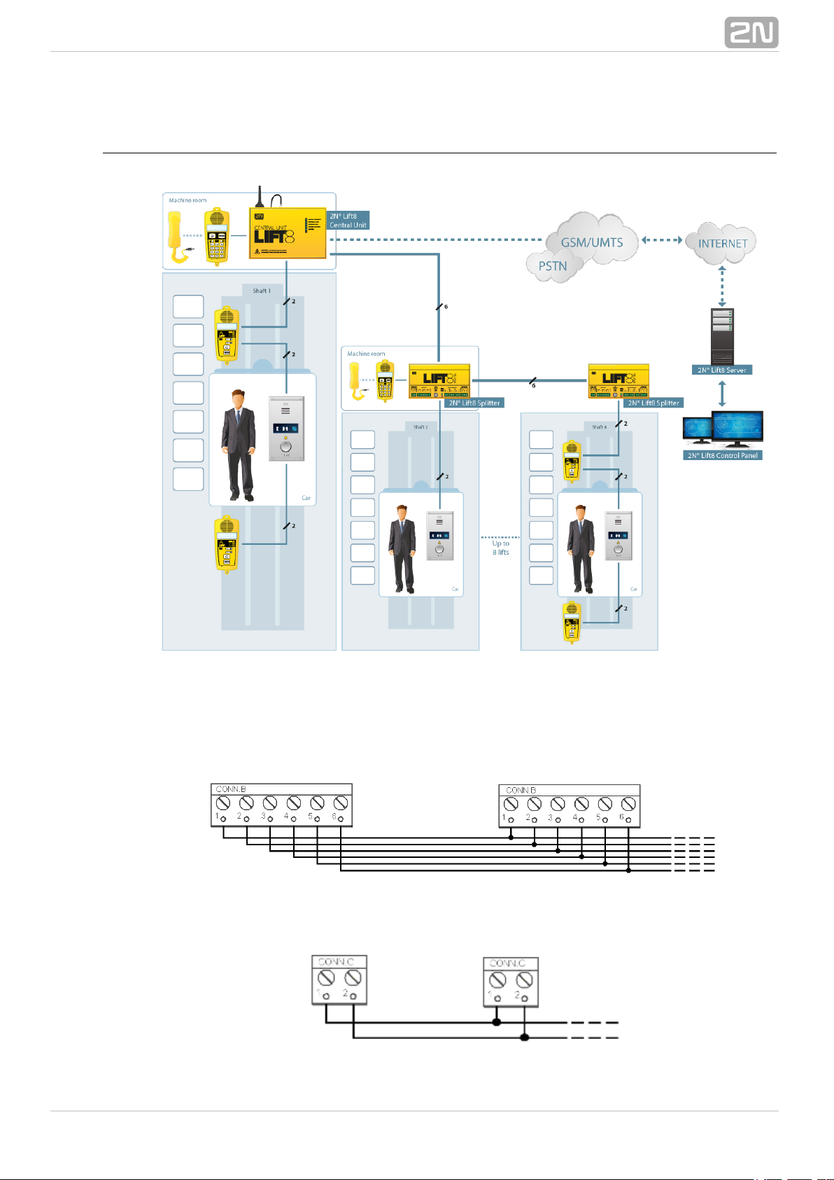
System Diagram
Example of Central Unit, Splitter and audio unit ConnectionFigure: 2N Lift8
®
Main bus
Audio unit bus
®
72N TELEKOMUNIKACE a.s., www.2n.cz
Page 8
1.2 Components and Associated Products
2N Lift8 System Components
®
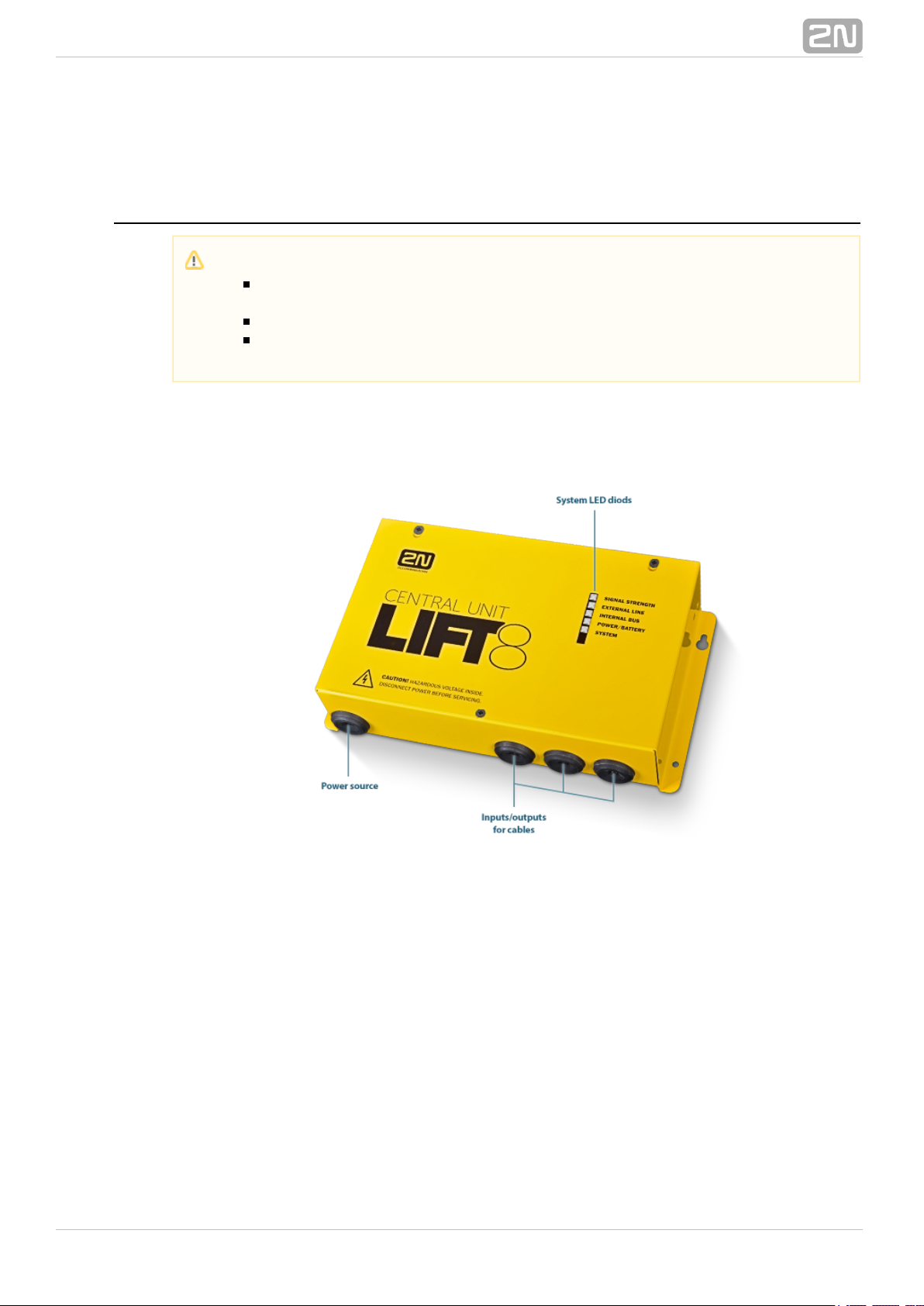
918600 2N Lift8 Central Unit
®
Central UnitFigure: 2N Lift8
®
For connection of up to 8 lifts to a GSM/UMTS/PSTN line. Including a power EURO cable
and rechargeable battery. USB interface for configuration.
Notification
The components of the system cannot be used outside this2N®Lift8
system.
The audio units cannot be connected to a telephone line without the !CU
When shared by multiple shafts, the audio units cannot be connected
without the and splitters.CU
®
82N TELEKOMUNIKACE a.s., www.2n.cz
Page 9

918620E 2N Lift8 Splitter
®
SplitterFigure: 2N Lift8
®
For – lift audio unit interconnection.CU
918610E 2N Lift8 Audio Unit – Cabin Universal
®
(Normal version)
Audio Unit – Cabin UniversalFigure: 2N Lift8
®
Audio unit electronics for lift cabin buiiding in. Including speaker and microphone
(HandsFree). Connection terminals for all prescribed elements and door opening signal
input (optional).
®
92N TELEKOMUNIKACE a.s., www.2n.cz
Page 10

918610EX 2N Lift8 Audio Unit – Cabin Universal – Cable Version
®
Contains LED, microphone and speaker connected to cables.
Audio Unit – Cabin Universal – Cable VersionFigure: 2N Lift8
®
918611E 2N Lift8 Audio Unit – Machine Room/Control Centre
®
Audio Unit – Machine Room/Control CentreFigure: 2N Lift8
®
Audio unit for the machine room/control centre. Contains receiver (optional) and
keypad for easy control. Makes it possible to communicate with other system audio
units and configure the without a PC. Equipped with an external siren connector.CU
Can be shared by multiple lifts (shafts). Robust yellow cover.
®
102N TELEKOMUNIKACE a.s., www.2n.cz
Page 11

918612E 2N Lift8 Audio Unit – Shaft
®
Audio Unit – ShaftFigure: 2N Lift8
®
Audio unit for cabin roof and shaft or cabin bottom. Robust yellow cover. HandsFree
mode, ALARM button and Triphony, LED indicators. Not intended for use in the cabin.
918613E 2N Lift8 Audio Unit – Compact
®
Audio Unit – CompactFigure: 2N Lift8
®
Robust, heavy-duty design. Standard-sized ALARM button including signage for the
blind and backlit pictograms (hardened glass). Easy cabin wall mounting. Easy 2-wire
connection.
®
112N TELEKOMUNIKACE a.s., www.2n.cz
Page 12
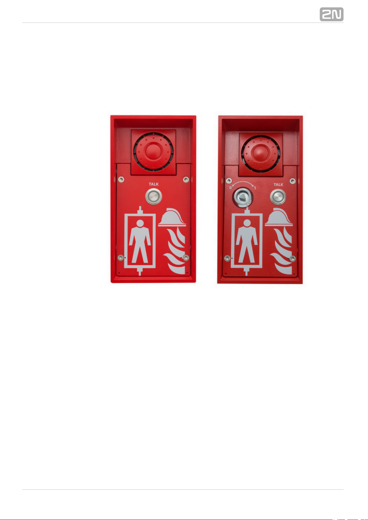
918615ZK 2N Lift8 Audio Unit – Fireman (1 button)
®
918615E 2N Lift8 Audio Unit – Fireman (knob + 1 push-to-talk
®
button)
Audio Unit – FiremanFigure: 2N Lift8
®
Used for fire fighting operations. Activates top priority calls.
918610FZK 2N Lift8 Audio Unit – Fireman DPS (1 button)
®
918619E 2N Lift8 Audio Unit – Fireman DPS (knob + 1 push-to-talk
®
button)
®
122N TELEKOMUNIKACE a.s., www.2n.cz
Page 13
Audio Unit – Fireman DPSFigure: 2N Lift8
®
Used by fire fighting operations. Activates top priority calls.
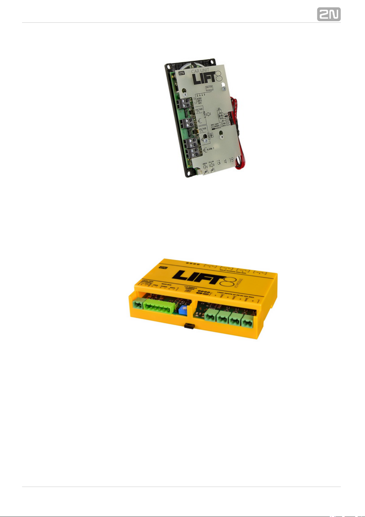
918620E 2N Lift8 I/O Module
®
I/O ModuleFigure: 2N Lift8
®
Contains logical inputs and switch relays.
®
132N TELEKOMUNIKACE a.s., www.2n.cz
Page 14

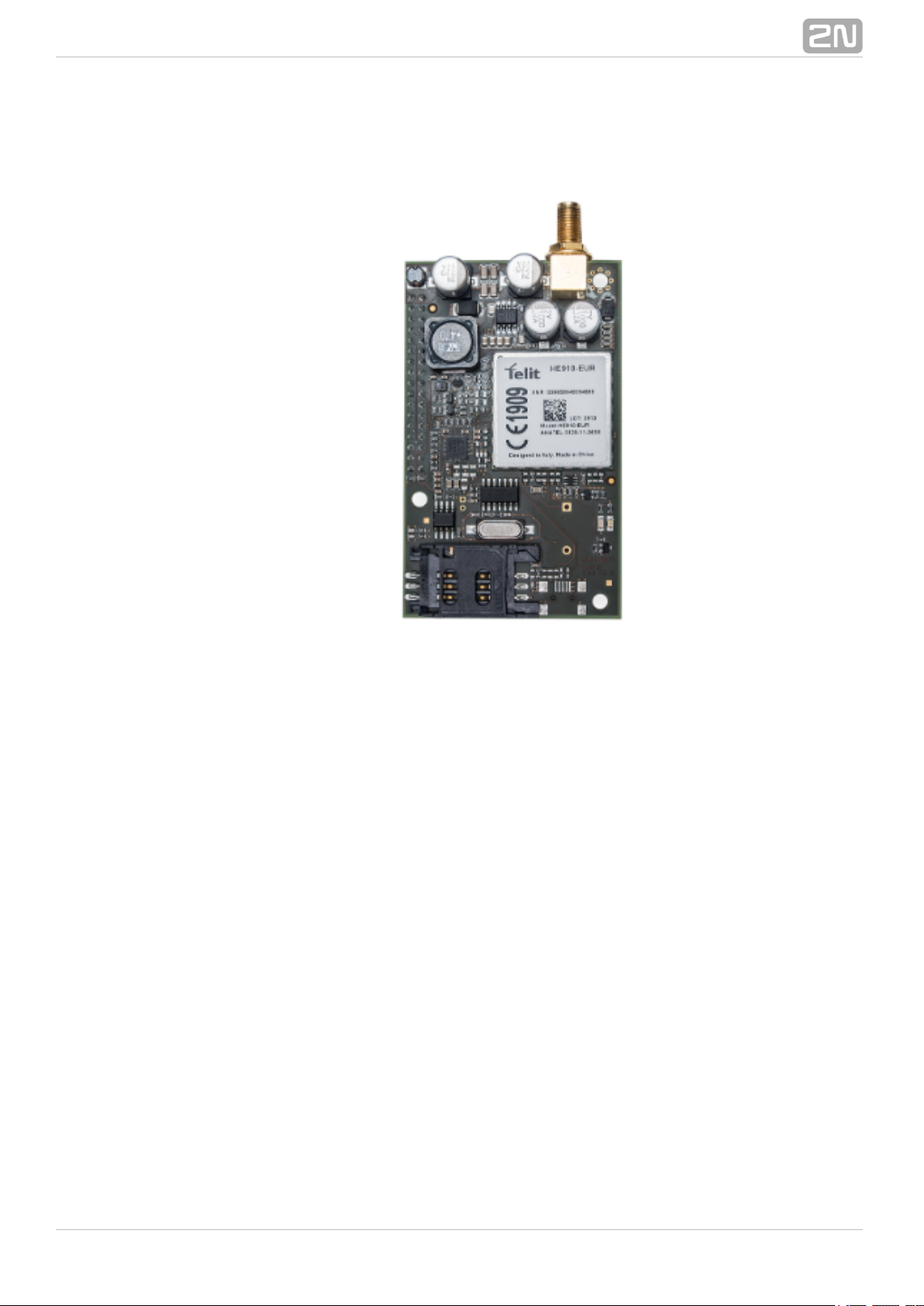
918650E 2N Lift8 GSM Module
®
GSM ModuleFigure: 2N Lift8
®
For central unit connection via a mobile network. Optional data connection for remote
system configuration.
®
142N TELEKOMUNIKACE a.s., www.2n.cz
Page 15
918651E 2N Lift8 UMTS Module
®
UMTS ModuleFigure: 2N Lift8
®
For central unit connection via a mobile network. Optional data connection for remote
system configuration.
®
152N TELEKOMUNIKACE a.s., www.2n.cz
Page 16

918652E 2N Lift8 PSTN Module
®
PSTN ModuleFigure: 2N Lift8
®
For central unit connection via an analogue line.
®
162N TELEKOMUNIKACE a.s., www.2n.cz
Page 17

918653E 2N Lift8 VoIP Module
®
VoIP ModuleFigure: 2N Lift8
®
For central unit via a VoIP line.connection
®
172N TELEKOMUNIKACE a.s., www.2n.cz
Page 18

Cooperating 2N Applications
®
918700E 2N Lift8 Service Tool
®
Figure: 2N Lift8®Service Tool
The is intended for remote supervision and2N Lift8 Service Tool® application
configuration of the communicators.2N Lift8
®
918700E 2N Lift8 Control Panel
®
Figure: 2N Lift8 Control Panel
®
The application is intended for administration of users, lifts2N Lift8 Control Panel
®
®
182N TELEKOMUNIKACE a.s., www.2n.cz
Page 19
and authorisations.
918700E 2N Lift8 Communicator
®
Figure: 2N Lift8 Communicator
®
The is intended for receiving alarm calls by the2N Lift8 Communicator®application
dispatcher.
918700E 2N Lift8 Server
®
Figure: 2N Lift8 Server
®
®
192N TELEKOMUNIKACE a.s., www.2n.cz
Page 20

The processes check calls and mediates communication2N Lift8 Server®application
between the s and PC applications.CU
Associated 2N Products
®
918655E – 2N Lift8 External Pictograms Driver
®
External Pictograms DriverFigure: 2N Lift8
®
Transforms the cabin into universal pilot lamps.2N Lift8
®
LED outputs
®
202N TELEKOMUNIKACE a.s., www.2n.cz
Page 21
1.3 Upgrade
The table below sums up the User Manual upgrade changes made so far.
Manual
version
Description of changes
1.0.0
Firmware 1.0.0
Basic version
1.5.0
Firmware 1.5.0
VoIP parameters added
Internal splitter configuration optionfour-lift
(up to four cabin units can be connected to one internal splitter
with lift 1-4 identification)
1.6.0
Firmware 1.6.0
Fireman
I/O modules (inputs only)
Configurable rechargeable battery capacity
New alarm call protocols added (shaft/announcer identification)
Dial-in option (for PSTN modules with non-standard tones)
CZ, EN, RU language support
Important warnings -Upgrade ServerDatabase from ver. 1.5.x to ver. 1.6.x
PSurveillance mode intheControl anel
Improvements inapplications
®
212N TELEKOMUNIKACE a.s., www.2n.cz
Page 22

1.4 Terms and Symbols Used
Symbols Used
The following symbols and pictograms are used in the manual:
Future Functions, New Features
The grey-marked text in this document designates the functions and features that are
under preparation or development at present.
Safety
abide by this information to prevent persons from injury.Always
Warning
abide by this information to prevent damage to the device.Always
Caution
Important information for system functionality.
Tip
Useful information for quick and efficient functionality.
Note
Routines or advice for efficient use of the device.
®
222N TELEKOMUNIKACE a.s., www.2n.cz
Page 23

2. Description and Installation
The section is divided according to system components into the following subsections:
2.1 PSTN/GSM/UMTS/VoIP Central Unit
2.2 Splitter
2.3 Audio Unit – Cabin Universal
2.4 Audio Unit – Machine Room
2.5 Audio Unit – Shaft
2.6 Audio Unit – Compact
2.7 PSTN Module
2.8 GSM/UMTS Module
2.9 VoIP Module
2.10 Audio Unit – Fireman
2.11 I/O Module
Each subsection includes:
Description of Components
Before You Start
Fitting
Electrical Wiring
®
232N TELEKOMUNIKACE a.s., www.2n.cz
Page 24

2.1 PSTN/GSM/UMTS/VoIP Central Unit
Description
Central UnitFigure:
®
242N TELEKOMUNIKACE a.s., www.2n.cz
Page 25

Figure: Central Unit Indication Elements
®
252N TELEKOMUNIKACE a.s., www.2n.cz
Page 26

Figure: Central Unit Connectors
There are a USB connector and reset button to the right of the (see the figureCU
below).
Figure: Reset ButtonUSB Connector and
®
262N TELEKOMUNIKACE a.s., www.2n.cz
Page 27

Reset button function
– press the button quickly.Reset equipment
– press and hold the button until all the LEDs turn red.Restore factory values
Then release the button and wait until the SYSTEM LED flashes yellow. Now press
the button quickly to delete all the user settings.
– press and hold the buttonZero backup rechargeable battery life counter
until all the LEDs turn red. Then release the button and wait until the
POWER/BATTERY LED flashes yellow. Now press the button quickly. Perform this
function after replacing the backup rechargeable batteries with new ones only!
– press and hold the button until all the LEDsCheck system completeness
turn red. Then release the button and wait until the INTERNAL BUS LED flashes
yellow. Now press the button quickly to make the system supervise all the
installed equipment (splitters, Audio Units etc.) for proper connection and
function.
– press and hold the button until allDelete central unit software completely
the LEDs turn red. Then release the button and wait until the SYSTEM LED
flashes red. Now press the button quickly. CAUTION: after performing this
function you can only restore the normal function of the device using a PC!
USB Port Connection
Recommendation
Do not keep your PC connected for a long time unless necessary to reduce the
computer damage due voltage surge from the telephone line during storms, for
example.
Before You Start
CU installation conditions
The (hereinafter referred to as ) is not intended for outdoor use. Central Unit CU
Do not install the onto vibration-producing machines. CU
Install the vertically to allow air flow for cooling purposes (never cover the CU CU
with any cloth or install it in another closed box).
You may install the into the lift switchboard unless the temperature exceedsCU
the acceptable limit. Remember that a higher ambient temperature reduces the
life of backup rechargeable batteries in the .CU
It is recommended that the should be operated in the upright position withCU
the cable openings at the bottom. Such mounting position ensures the lowest
temperatures and thus the longest life of the rechargeable batteries. Horizontal
mounting is also possible. The upright position with the cable openings at the top
(upside down) is forbidden!
After mounting the check that the equipment is firmly fixed in place andCU
cannot come loose and drop down into the shaft.
Warning
during the warranty period.Do not open the CU
Open the only to replace after theCU the rechargeable batteries
warranty period.
®
272N TELEKOMUNIKACE a.s., www.2n.cz
Page 28

1.
2.
3.
4.
5.
6.
7.
8.
9.
10.
Product Completeness Check
Check whether the product package is complete before installation:
1 central unit
1 main bus terminal
4 bus connection terminals
4 wall plugs
4 wall plug screws
8 cable ties
1 battery connecting cables
1 brief manual
1 warranty sheet
drilling template
CU Mounting
It is recommended to install the in a room that is secured against unauthorisedCU
persons, such as the lift machine room, switching station etc. On an easily accessible
place there is a risk of telephone line misuse or SIM card misappropriation .
The is mounted on a wall with the included wall plugs and screws. CU
CU Electrical Installation
Putting in operation
Keep the disconnected from the mains.CU
Loosen the three screws on the upper cover of the CU.
Move the upper cover of the in such a way that you can remove it.CU
When removing the cover, proceed with caution, be careful about the earth wire
connecting the cover with the bottom part. Do not disconnect the wire unlessCU
there is a reason to do so!
Using the slide-on terminals supplied with the device, connect the Audio Units,
splitters (if there are 2 and more lift shafts) and other components of the system
with the Adhere to polarity!CU.
Install a PSTN, GSM or UMTS module unless installed on the . Abide by theCU
instructions given in the Instructions for Use of the given module (refer to Subs.
2.7 or 2.8).
Connect an analogue telephone line to the PSTN module if used (use a telephone
connector or the terminal board on the module). Do not forget to connect an
antenna to the GSM/UMTS module is used and insert a SIM card!
Connect the rechargeable battery jumper link (see the next subsection –
Rechargeable Battery State Check) to activate the rechargeable battery function.
Replace the upper cover on the and tighten the cover fitting screws. Doing soCU
make sure that the earthing wire is connected to the cover!
Connect the power cable to a 230V socket.CU
Caution
If you connect one lift shaft only, it is not necessary to connect the
splitters. Use the splitters only if you want to connect 2 or more lift shafts.
®
282N TELEKOMUNIKACE a.s., www.2n.cz
Page 29
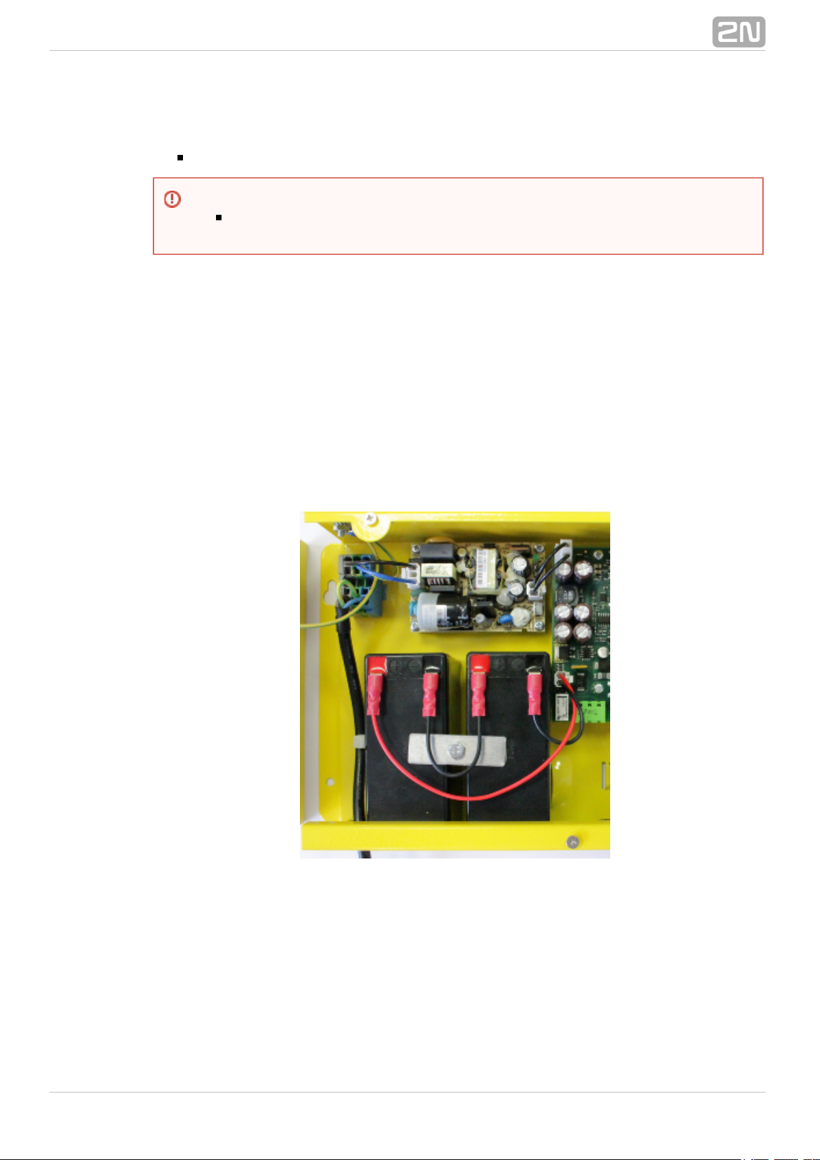
Power supply
The is powered by 100–240V mains power.CU
Rechargeable Battery Connection and State Check
Procedure:
1. Keep the disconnected from the mains.CU
2. Loosen the three screws on the upper cover of the CU.
3. Move the upper cover of the in such a way that you can remove it.CU
4. When removing the cover, proceed with caution, be careful about the earth wire
connecting the cover with the bottom part. Do not disconnect the wire unlessCU
there is a reason to do so!
5. Interconnect the rechargeable batteries and connect them with the motherboard
using a FASTON cable (see the figure below). Mind the polarity.
6. Replace the upper cover on the and tighten the cover fitting screws. DoingCU
so make sure that the earthing wire is connected to the cover!
7. Connect the power cable to a 230V socket.CU
After plugging the into the socket the LED (Power/battery) should start to flashCU
(charging). The charges the rechargeable batteries until fully charged. After some CU
time the flashing green LED (charging) should change to a permanently illuminated
green LED (battery charged).
Warning
Never connect an AC source or unstabilised DC source to avoid CU
damage.
®
292N TELEKOMUNIKACE a.s., www.2n.cz
Page 30

Rechargeable Batteries
Splitter – CU Bus Connection
Interconnect the and splitter using a 6-wire main bus (power + - , audio + - , dataCU
+ - ). Mind the polarity.
Warning
Adhere to the polarity of the rechargeable batteries! When the polarity of
the batteries is reversed, there is a danger of fire or explosion or damage
to the electronics.CU
Caution
If backup rechargeable batteries are used for the power supply,2N Lift8
®
the required backup of up to 1 h is guaranteed only if up to 20 audio units
are connected in the system.
The required 1h backup is not guaranteed if more than 20 audio units are
installed.
®
302N TELEKOMUNIKACE a.s., www.2n.cz
Page 31

Main bus
1 … Main bus power +
2 … Main bus power 3 … Main bus audio +
4 … Main bus audio 5 … Main bus data +
6 … Main bus data -
Audio Units – Splitter (CU) Bus Connection
(the is used if one lift shaft is connected)CU
Interconnect the Splitter ( ) and Audio Units using a two-wire bus. Mind the polarity.CU
Audio unit bus
1 … Bus for Audio Units +
2 … Bus for Audio Units -
Caution
6-wire
Use unshielded wires of the cross-section of 0.75 mm .
2
The maximum total cable length is 30 m with the cross-section of
0.75mm .
2
For higher lengths, enlarge the supply pair cross-section: PWR (60m
– 1.5mm , or 100m – 2.5mm ).
2 2
®
312N TELEKOMUNIKACE a.s., www.2n.cz
Page 32

Termination Resistance
Connect the termination resistance connector to the first and last device connected to
the bus: CU, splitter or I/O module.
Caution
2-wire
Use unshielded wires of the cross-section of 0.75 mm .
2
The maximum total length per shaft is 600 m.
With multi-strand cables, always use a pair of wires which match
each other.
With a tow cable, consider the cable length too.
With special cables (to the cabin), use the neighbouring wires and
make sure that the nearest surrounding wires do not radiate
interference (power wire, video signal etc.).
Tip
Do not lead the bus close to power cables, especially in long-distance
sections.
Branch the bus to shorten the total length of sections.
Safety
The bus is electrically isolated from the telephone line circuits according to
the EN60950 standard requirements and its low voltage cannot cause any
electrical accident.
Caution
Find the 2-pin termination resistance connector between the main bus
connector and audio unit connectors (see the figure below).
By default, the termination resistance is connected (jumper mounted).
®
322N TELEKOMUNIKACE a.s., www.2n.cz
Page 33

Examples of connection:
®
332N TELEKOMUNIKACE a.s., www.2n.cz
Page 34

CU Connection to Telephone Network
You can connect the to any of the following telephone networks: CU
PSTN
PBX
GSM
UMTS
VoIP
PSTN
works in a broad band regardless of polarity and line parameters (refer to 2N Lift8
®
Technical Parameters). Connect it using the enclosed cable with an RJ–12 terminal. It
is the most reliable and simplest connection. The disadvantage is the operating cost
(fixed fee).
Caution
Only one may be connected to one telephone line and no other endCU
telephone equipment may be connected to the line including a product
through which the telephone line goes (so-called priority connection –
electronic burglar alarm, e.g.).
No dual or party lines may be used.
No telephone “multiplugs” (adaptors), even the smart ones, may be used.
Never connect to an ISDN line.2N Lift8
®
®
342N TELEKOMUNIKACE a.s., www.2n.cz
Page 35

Telephone line requirements
The line must not be a dual or party one.
The telephone socket and its wiring are usually the network provider's property
and may not be tampered with.
Other recommendations
Notify the telephone network provider of your installation and submit2N Lift8
®
certification upon request.
Your follow-up wiring must comply with the relevant safety regulations.
You are recommended to secure your cabling against pirate connection (with a
telephone lock, e.g.).
Connection via PBX (Private Branch Exchange)
This is the least-cost solution where a PBX and an unused PBX line are available.
PBX line requirements
The PBX to be used must work reliably even in the case of power outage. Large
PBXs are mostly equipped with a back-up power supply, smaller PBXs usually use
PSTN line redirection in the event of power failure. Consult the problem with the
technician responsible for your PBX. An error during power outage may result in
calling an undesired station.2N Lift8
®
Relevant call access rights have to be assigned to the PBX line to be used (use a
standard telephone set to check whether the line can make outgoing calls to all
the required numbers).
While programming, enter the necessary PSTN code (typically a zero), or
(preferably) make the PBX not require a prefix (so-called automatic connection to
the provider's telephone line).
To make the control room – lift calls, you have to know the extension number
and how to get through to it (dial-in, DISA, operator).
The control room – lift connection may not depend on the operator’s presence;
no call forwarding to a fax/answering machine in the night mode is allowed, etc.
Other recommendations
Make an agreement with the PBX owner regarding operating costs (2N Lift8
®
outgoing calls are billed at the owner‘s expense with the exception of free calls
via “green lines”).
GSM
This is used in particular where no PSTN line is available.
Tip
If there is permanent manning in your building (security staff,
receptionist), train the personnel how to rescue people and program 2N
®
to call this service. Lift8
®
352N TELEKOMUNIKACE a.s., www.2n.cz
Page 36

Recommendation
In places with a poor signal quality find an appropriate place or use a special
(directional) antenna.
Protect the SIM card from theft.
If a prepaid SIM card is used, make sure that the credit is monitored and
topped up in time.
UMTS
This is used in particular where no PSTN line is available. If is connected via2N Lift8
®
UMTS, the system can be configured remotely using the appli2N Lift8 ®Service Tool
cation.
Recommendation
In places with a poor signal quality find an appropriate place or use a special
(directional) antenna.
Protect the SIM card from theft.
If a prepaid SIM card is used, make sure that the credit is monitored and
topped up in time.
Operation without SIM card or PSTN line
can be used as an intercom without an inserted SIM card or2N Lift 8
®
connected PSTN line during the lift fitting time. In this case do not enable the
lift blocking function until the telephone line is connected.
VoIP
VoIP is the cheapest solution where a reliable Internet connection is available.
®
362N TELEKOMUNIKACE a.s., www.2n.cz
Page 37

2.2 Splitter
Description
The splitter helps extend installations by interconnecting audio units in multiple lift
. shafts (audio units can be connected directly to the in one-shaft installations)CU It is
connected with the via six wires (power, audio, data). A s are connected toCU udio unit
the splitter using a two-wire bus. The splitter also contains a make/break contact for
the lift blocking function. There can be up to 7 splitters (according to the count of lift
shafts).
Each splitter must be configured for a different address (lift shaft number) for the
system to work. The addresses are 2–8 (lift 2–8). Lift 1 is the .CU
The splitters are connected in series, i.e. one after another (never in parallel), to avoid
system instability. The termination resistance (jumper) is mounted on the last splitter
.or IO module (furthest from the )CU
SplitterFigure: 2N Lift8
®
Caution
Local power supply is not supported yet.
®
372N TELEKOMUNIKACE a.s., www.2n.cz
Page 38

Electrical Installation
Main Bus Connection
Remove the push-in terminal board from the main bus connector and connect six wires
from the maintaining the polarity (power + -, audio + -, data + -). See the printedCU
figure on the splitter cover.
Main bus
1 … Main bus power +
2 … Main bus power 3 … Main bus audio +
4 … Main bus audio 5 … Main bus data +
6 … Main bus data -
Bus Connection between s and SplitterAudio Unit
Interconnect the splitter and a s using a two-wire bus maintaining polarity.udio unit
Audio unit bus
1 … Bus for Audio Units +
2 … Bus for Audio Units -
Warning
Maintain the connection polarity to avoid a error.2N Lift8
®
®
382N TELEKOMUNIKACE a.s., www.2n.cz
Page 39

Address Configuration
Configure the splitter address for the given lift using a 10-position switch 0–9 (see the
figure).
Configure lift 2–8 as 2–8 (set the switch to position 5 for lift 5, e.g.).
Audio Unit Connection
Connect up to 5 s to each splitter. As the splitter has only 3 terminaudio unit audio unit
als, connect 1–2 in parallel. Remove the slide-on terminals from the audio unit audio
connectors and connect the twin-wire. Adhere to polarity to avoid the erunit audio unit
ror. Refer to the schemes printed on the splitter and for connection polarity.audio unit
Requirements
Connect up to 2 s to one terminal.audio unit
With multi-strand cables, always use a pair of wires which match each other. In
standard UTP cables the paired wires are twisted around each other.
With special cables (to the cabin), use the neighbouring wires and make sure
that the nearest surrounding wires do not radiate interference (power wire, video
signal etc.).
Recommendation
Do not run the bus near power wires, especially long sections.
.Branch the bus to shorten the total length of sections
Lift Blocking Function Connection
Lift blocking is enabled by the contact breaking (opening) when there is a telephone
line (PSTN, GSM, UMTS, VoIP) fault or if the rechargeable batteries are2N Lift8
®
almost flat. Connect the contact to the relevant input of the control electronics of the
lift/group of lifts. The control electronics must ensure that, after the contact opening,
the lifts in operation go down to the nearest station and the doors open.
Warning
The bus is electrically isolated from the telephone line circuits according to
the EN60950 standard requirements and its low voltage cannot cause any
electrical accident.
Caution
This function may be mandatory depending on the regulations applicable
and time of installation.for the given country
®
392N TELEKOMUNIKACE a.s., www.2n.cz
Page 40

Termination Resistance
Figure: Termination Resistance Off
Caution
Find the 3-pin termination resistance connecting jumper between the
main bus connector and lift number switch.
Connect the jumper to the first and last device (CU, splitter or I/O
module) on the bus. Refer to the CU describing section for more details on
termination resistance mounting.
By default, the termination resistance jumper is off.
®
402N TELEKOMUNIKACE a.s., www.2n.cz
Page 41

Mounting Types
See below for the mounting types and necessary components. Install the device on
sites not exposed to water leakage or condensation.
Wall Mounting
Use appropriate wall plugs and screws for mounting (not included in the delivery).
Hang the device using the pre-drilled holes on the device bottom.
Figure: Wall Mounting
DIN Rail Mounting
Mount the device on a standard TS 35 DIN rail. The recommended DIN rail length is 14
cm.
Figure: DIN Rail Mounting
®
412N TELEKOMUNIKACE a.s., www.2n.cz
Page 42

Caution
The warranty does not cover any defects or failures of the product arisen
as a result of improper mounting in contradiction to these instructions.
A wrong mounting procedure may lead to damage to the electronics due
to water infiltration. The splitter circuits are constantly under voltage and
water leakage causes electrochemical reaction. No warranty can be
claimed for products damaged in this manner!
®
422N TELEKOMUNIKACE a.s., www.2n.cz
Page 43

2.3 Audio Unit – Cabin Universal
Description
The user does not come into a direct contact with this product. The control and
indication elements depend on the specific installation. The functions of the indication
elements correspond to the applicable standards
Figure: Audio Unit – Cabin Universal
Before You Start
Installation Conditions
The panel has to be installation-ready, including speaker perforation.
The panel has to be equipped with the following obligatory elements:
ALARM button;
illuminated pictogram “Request received”;
illuminated pictogram “Connection made”.
The above mentioned elements have been located as required by the applicable
regulations.
There must be free space of at least 65×130×20 mm behind the panel.
®
432N TELEKOMUNIKACE a.s., www.2n.cz
Page 44

Product Completeness Check
Check the product for completeness before installation.
The cabin package contains (assembled):audio unit
1 electronics board
4 terminals slid onto the board; see the photo
1 jumper slid onto the board; see the cover printing
1 mounting panel
1 speaker connected directly or by cable
1 microphone connected directly or by cable
1 cover with printing
5 tightening straps
Mounting
Electronics Mounting
This is intended for mounting behind the lift control panel. Typically, theaudio unit
panel is ready for installation as shown in the drawing below:
Figure: Mounting Hole Dimensions for Audio Unit – Cabin Universal
To mount the , you need 4 electrically spot welded or screws, aaudio unit M3 M4
sufficiently perforated speaker area and a microphone hole. In emergency, you can fix
®
442N TELEKOMUNIKACE a.s., www.2n.cz
Page 45

the on a perfectly degreased surface with a high-quality double-sided foamaudio unit
self-adhesive tape.
Separate Microphone Mounting
If the microphone is supplied separately with a cable on a 25×25 mm large board with
self-adhesive foil, j hole in the panel (one hole must haveust glue it directly behind any
the minimum diameter of 5 mm, a group of smaller holes must have the same total
area). Be sure to degrease and clean the surface carefully before!
Requirements
The minimum distance between the loudspeaker and microphone centres
A lower distance may lead to acoustic feedback. A greater distance is 90 mm.
(within the available 1m cable) does not matter.
The microphone must be stuck on so that it does not pick up (even in part!) the
acoustic pressure from the space behind the control panel. Such sensing might
result in acoustic feedback since the speaker strongly radiates sound into the
cavity.
Separate Speaker Mounting
The speaker is equipped with a cable and can be separated from the electronics (simply
pulled out) within the reach of the cables delivered (1m). This option is useful where
there is not enough space for the whole electronic equipment. Fit the speaker
according to the instructions below:
While gluing the speaker choose such procedures or adhesives that prevent
membrane damage by adhesives and volatile substances or heat.
We recommend you to keep the speaker sealed to eliminate vibrations and
provide electrical insulation.
Frequently Asked Questions about Speaker
Is it possible to use a common speaker for the communicator and floor
?announcer
No, it is not possible.
May I use a speaker of my own?
Yes, but make sure that the impedance is 64 Ω. By doing this you assume
responsibility for sufficient volume and frequency range.
May I place the speaker on the cabin ceiling?
This placement is not recommended.
May I use a longer cable to the speaker?
For the speaker yes, but we do not recommend it for the microphone.
Safety
Leave no gap between the lift control panel and the surface toaudio unit
avoid acoustic speaker fault and acoustic speaker-microphone feedback.
Do not use this type of in a position other than mounted on aaudio unit
sufficiently large board. The acoustic properties of an uninstalled audio
cannot be guaranteed.unit
®
452N TELEKOMUNIKACE a.s., www.2n.cz
Page 46

Electrical Installation
Description of Terminals, Connectors and Jumpers
Figure: Terminals, Connectors and Jumpers on Audio Unit – Cabin Universal
Terminals Connectors
1 Audio unit bus 7 “Connection made” LED
2 ALARM, voltage activation 8 “Request received” LED
3 ALARM, contact activation 9 Microphone connector (optionally)
4 CANCEL, voltage activation 10 Induction loop connector
5 CANCEL, contact activation 11 Speaker connector
6 Alarm 2 (set 2) 13 Servicing connector
Configuration jumpers Two LED signal lamps (other side)
12 positionAudio unit 1. (yellow) Request received
12 ALARM and CANCEL negation 2. (green) Connection confirmed
Note
If external LEDs are connected to connectors 7 and 8, LED indicators 1
and 2 will not be shining.
®
462N TELEKOMUNIKACE a.s., www.2n.cz
Page 47

1.
2.
3.
4.
5.
ocation ConfigurationAudio Unit L
The is configured as a cabin by default and so it is not necessaryaudio unit audio unit
to change the configuration. To use the in a room other than the lift cabin,audio unit
proceed as follows.
Procedure
Reconfigure the jumper on configuration jumper 12.
If there is poor access to the pins, you can remove the electronics cover. Slightly
loosen the four screws and shift the cover downwards. Now you can remove the
cover.
The first 4 pins serve for setting the location (1 – cabin ceiling, 2 –audio unit
cabin, default, 3 – under the cabin, 4 – shaft bottom).
Configure the required changes as printed on the electronics cover.
If you have removed the cover, put it back in the original position and tighten the
screw.
®
472N TELEKOMUNIKACE a.s., www.2n.cz
Page 48

Figure: Address Configuration for Audio Unit – Cabin Universal
Note
Make sure that two s do not have an identical address to avoidaudio unit
system error.
The position-setting jumpers are employed exceptionally, e.g. where a
certain type is used in a position other than normally intended.audio unit
To recover the initial address setting, follow the drawing on the cover.
®
482N TELEKOMUNIKACE a.s., www.2n.cz
Page 49

1.
2.
3.
Bus Connection
Pull the terminal out of connector 1 - Audio units bus, connect the bus audio units
wires and replace the terminal to connector 1. Mind the polarity.
ALARM Button Connection
Requirements
The ALARM button design (colour, symbol, keypad surface, mechanical operation)
and location have to meet the requirements of the particular installation.
Button control
Requirements
The ALARM button has to be equipped with a make or break (NO/NC) contact
that is not connected with any other circuit.
None of the ALARM button terminals may be connected electrically with any other
electrical circuit and no voltage source other than the NO/NC contact may be
connected to them.
If one of the ALARM contacts is connected to another circuit, an appropriate
isolation strength according to the applicable standards has to be ensured
between the contacts.
Procedure
Leave the ALARM terminal in the lower position (3).
If you use a make contact, leave the jumper as it is (5th pin on jumper 12) –
ALARM without jumper fitted (factory setting).
If you use a break contact, fit the jumper (5th pin on jumper 12) – ALARM
inverted – jumper fitted.
Warning
Connection to different, e.g. higher-voltage, cables leads to damage or
destruction of the .audio unit
Maintain polarity while connecting the to avoid error.audio unit audio unit
Caution
The is powered via a 2-wire bus. Disconnection of these wiresaudio unit
results in the switch-off.audio unit
Avoid the address duplicity.audio unit
®
492N TELEKOMUNIKACE a.s., www.2n.cz
Page 50

1.
2.
3.
1.
2.
3.
Voltage control
Requirements
DC 12 to 48V voltage
The voltage signal must be active even during a power failure.
Procedure
Move the ALARM terminal two pins up into position (2).
For activation by voltage connection, leave the jumper as it is (5th pin on jumper
12) – ALARM without jumper fitted (factory setting).
For activation by voltage disconnection, fit the jumper (5th pin on jumper 12) –
ALARM inverted – jumper fitted.
CANCEL Input Connection (Door Contact, Optional)
This input helps cancel a rescue request if the lift is fully functional. When the ALARM
button is pressed, the system waits for a pre-programmed period of time, which is a
little longer than the maximum lift running time. If the lift is functional, it arrives in the
required station within this timeout and opens the door. In that case, the rescue
request is cancelled. If the door does not open, the request is accepted.
Find out before installation whether the door opening signal is available in the lift cabin.
Requirements
If the lift has a double door, the signal must be active only if both the door sets
are open, i.e., if it is really possible to leave the cabin.
The door position signal has to work even in the case of power outage.
Contact control
Requirements
None of the contact outlets terminals may be connected electrically with any
other electrical circuit and no voltage source other than the NO/NC contact may
be connected to the CANCEL terminals.
Procedure
Leave the CANCEL terminal in the lower position (5).
f you use a make contact, leave the jumper as it is (6th pin on jumper 12) –
CANCEL without jumper fitted (factory setting).
If you use a break contact, fit the jumper (6th pin on jumper 12) – CANCEL
inverted – jumper fitted.
Warning
Ignoring the instructions above may lead to product damage.
®
502N TELEKOMUNIKACE a.s., www.2n.cz
Page 51

1.
2.
3.
Voltage control
Requirements
DC 12 to 48V voltage
Procedure
Move the CANCEL terminal two pins up into position (4).
For activation by voltage connection, leave the jumper as it is (6th pin on jumper
12) – CANCEL without jumper fitted (factory setting).
For activation by voltage disconnection, fit the jumper (6th pin on jumper 12) –
CANCEL inverted – jumper fitted.
LED Indicator Connection
The current LED technology makes it possible to achieve a relatively good light
intensity with a small current. If the lift indicators are illuminated with a sufficiently
efficient LED requiring a current of approx. 5 mA (with diode loss of about 2 V), no
power supply is needed. See the figure below for the connection.
Figure: Alternative LED Connection for Audio Unit – Cabin Universal
Warning
Ignoring the instructions above may lead to product damage.
The CANCEL function only works when the cabin is set to theaudio unit
cabin position (default).
Caution
Remember to program delayed calling to make the CANCEL connection
work successfully.
Refer to the electronics cover for the ALARM and CANCEL configuration
scheme.
®
512N TELEKOMUNIKACE a.s., www.2n.cz
Page 52

External Pictogram Driver
Description
The device transforms the Car Unit LED outputs into a universal pilot lamp,2N Lift8
®
whose outputs are capable of driving two lamps rated at the maximum of 36 Volts, 0.5
Amps. The outputs are galvanically isolated from the Car Unit. Since the lamp outputs
are polarity independent, both AC and DC power supplies can be used for powering the
lamps. To protect the Car Unit and Pictogram Driver against damage caused by shorts,
always use the included isolating tube when installing the device!
Wiring diagram
Note
The cables required for this configuration are not part of the standard
delivery but are available upon agreement.
In this configuration, the auxiliary indicators on the PCB are not
illuminated.
®
522N TELEKOMUNIKACE a.s., www.2n.cz
Page 53

Volume Configuration
Slightly loosen the four screws and shift the cover downwards. Now you can remove
the cover. Use the trimmer located in the bottom part of the electronics to set the
required volume level (see the figure below).
Induction Loop Connection
The regulations that apply to communicator installations may require a mandatory loop
for persons with defective hearing in the lift cabin. In that case, connect the loop to
connector (10) with any polarity. The loop including a 1m long cable can be part of
your delivery if agreed so.
Requirements
The induction loop has to be placed behind a non-metal, non-magnetic cover in
the control panel as the magnetic field of the induction loop cannot go through a
metal control panel.
The induction loop has to be labelled with an appropriate symbol (ear) placed
according to the applicable standards.
Caution
External pictograms are connected to connectors 7 and 8 on the cabin
audio unit.
The manufacturer, 2N TELEKOMUNIKACE a.s., hereby declares that the
External Pictogram Driver is in compliance with the essential2N Lift8
®
requirements and other relevant provisions of the 1999/5/EC Directive.
The Declaration of Conformity is attached to the basic module of 2N
®
and also available at .Lift8 www.2n.cz
Caution
Use the trimmer to set the best acoustic properties eliminating feedback.
®
532N TELEKOMUNIKACE a.s., www.2n.cz
Page 54

Rescue Process
The rescue (extrication) process is activated after the alarm call end.
The yellow LED keeps shining on the audio unit.
The service technician enters a valid password via the voice menu2N Lift8
®
to terminate the process.
When the rescue password is entered via the voice menu, the yellow LED goes
off on the audio unit and the 'Rescue process was terminated' is played.
Caution
Access the voice menu (during an incoming call to L8 or from the machine
room) to terminate the rescue process. Enter the administration menu (9)
and press (2) to terminate the rescue process. Enter the shaft number
(only if multiple audio units are involved in the rescue process) and enter
the rescue terminating password.
Warning
Remember to set the rescue password (parameter 992) to activate the
rescue function.
The rescue process can only be activated on a cabin audio unit configured
as the cabin (default audio unit setting).
®
542N TELEKOMUNIKACE a.s., www.2n.cz
Page 55

2.4 Audio Unit – Machine Room
Description
The machine room audio unit is intended for installation in the machine room or as an
intercom solution located in the reception. It has some compared with thedistinctive
other types:
The is equipped with a keypad.audio unit
The keypad helps you select various functions and program the system.
You can connect a handset to the for better acoustic properties inaudio unit
noisy environments.
You can connect an external siren to the for incoming call signalling.audio unit
You can configure the machine room to be shared by multiple lifts.audio unit
®
552N TELEKOMUNIKACE a.s., www.2n.cz
Page 56

1.
2.
3.
4.
5.
Operation
This type of is operated by qualified people (lift maintenance staff,audio unit
e.g.).
Push the TRIPHONY button to activate voice communication with the other audio
of the same lift. Push and hold the button for over 2 seconds to activateunits
communication with another lift (to display a voice menu and select the required
lift number).
Push the ALARM button to call the control centre, for example. The audio unit
calls the numbers configured in the ALARM memory – set 2 (021–026). The
ALARM button illumination (not required by default) helps you find and activate
the easily in the dark.audio unit
When you press the ALARM or TRIPHONY button, the function is called up
immediately. Speak HandsFree or use a handset for better acoustic properties.
Press for more than 2 s to display the voice menu.
Before You Start
Requirements
Connect a handset supplied by the manufacturer to the to avoidaudio unit
handset operation error.
Product Completeness Check
Check the product for completeness before installation.
1 audio unit
1 handset
2 wall plugs
2 wall plug screws
7–8 jumpers for common machine room configuration
Mounting
The is typically mounted on a wall using the wall plugs and screws includedaudio unit
in the delivery.
Caution
If no number is specified in the ALARM memory – set 2 (021–026), the
dials the numbers defined in the ALARM memory – set 1audio unit
(011–016).
Push the ALARM button to call the control room or machine room audio
configured as an intercom.unit
The ALARM and TRIPHONY buttons shine even at relax.
®
562N TELEKOMUNIKACE a.s., www.2n.cz
Page 57

Electrical Installation
Description of Connectors
There are 3 connectors to the right under the cover:
Figure: Machine Room Audio Unit Connectors
Address Configuration
There is a group of jumpers u . Do not use any of themnder the transparent front cover
if the machine room is only intended for the given lift. The identifies itself asaudio unit
the machine room for the given lift.
If the machine room is to be shared by multiple lifts, configure the corresponding pins
1–8 for the lifts to share the machine room (numbered 1–8 from left to right 1–8).
Group of 8 jumpers for address configuration: If the machine room is shared by
multiple lifts, use one and configure several addresses using theaudio unit
included jumpers. The other types do not have this possibility!audio unit
Note
This audio unit is always configured as the machine room and cannot have
a different location.
Note
Having set more addresses for the , press the TRIPHONY buttonaudio unit
to activate communication of the lift with the lowest of theaudio units
configured addresses.
Caution
.Avoid the address duplicityaudio unit
®
572N TELEKOMUNIKACE a.s., www.2n.cz
Page 58

Bus Connection
Loosen the screws to the right and open the connector cover. There is just one
connector under the cover: a bus connector. Pull out the terminal from the connector,
connect the wires and replace the terminal. Make sure that the polarity is maintained.
Handset Connection
Order an additional handset for your . The handset is delivered including aaudio unit
cable with telephone end pieces.
Testing
Connect a handset and push and hold for over 2 s to display the voice menu for
the function test. If the handset does not work, the voice menu will be played from the
speaker.audio unit
Volume Configuration
Open the protective door on the and adjust the volume .audio unit using the trimmer
Warning
Connection to different, e.g. higher-voltage, cables leads to damage or
destruction of the audio unit.
Maintain polarity while connecting the to avoid erroraudio unit audio unit .
Caution
The is powered via a 2-wire bus. Disconnection of these wiresaudio unit
results in the switch-offaudio unit .
Caution
If the handset is not connected, the works in the HandsFreeaudio unit
mode.
A handset of a type other than that supplied by the manufacturer may not
work.
®
582N TELEKOMUNIKACE a.s., www.2n.cz
Page 59

Caution
Use the trimmer to set the best acoustic properties eliminating feedback.
Volume configuration only works in the HandsFree mode.
®
592N TELEKOMUNIKACE a.s., www.2n.cz
Page 60

2.5 Audio Unit – Shaft
Description
This audio unit is designed for installation on the lift shaft bottom or lift cabin roof, or
wherever it is necessary to communicate (during lift maintenance, e.g.). The audio unit
is enclosed in a robust yellow cover. It is not intended for outdoor use but perfectly
tolerates the conditions in lift shafts: is resistant against fall of small objects, dripping
oil, etc. The ALARM button activates the control centre connection, the TRIPHONY
bottom enables conference connection with the other a s of one and the sameudio unit
lift. The contains a built-in microphone and a speaker. A handset can beaudio unit
connected for better acoustic properties. Thanks to its size and robustness, the audio
has a very good, strong sound. unit
®
602N TELEKOMUNIKACE a.s., www.2n.cz
Page 61

1.
2.
3.
4.
5.
Operation
This type of is operated by qualified people (lift maintenance staff,audio unit
e.g.).
Push the TRIPHONY button to activate voice communication with the other audio
of the same liftunits .
Push the ALARM button, for example, when someone falls down the shaft.
The calls the numbers configured in the ALARM memory – set 2audio unit
(021–026).
The ALARM button illumination (not required by default) helps you find and
activate the easily in the darkaudio unit .
Before You Start
Product Completeness Check
Check the product for completeness before installation.
1 audio unit
2 wall plugs
2 wall plug screws
Requirements
This type of has no specific requirements.audio unit
Mounting
The is typically mounted on a wall using the supplied wall plugs and screws.audio unit
There is a drilling template in the product package.
Caution
If no number is specified in the ALARM memory – set 2 (021–026), the
dials the numbers defined in the ALARM memory – set 1audio unit
(011–016).
Push the ALARM button to call the control room or machine room audio
configured as an intercom.unit
The ALARM and TRIPHONY buttons shine even at relax.
Caution
The is not intended for outdoor installations.audio unit
®
612N TELEKOMUNIKACE a.s., www.2n.cz
Page 62

1.
2.
3.
Electrical Installation
Connectors
The has one connector for bus connection. The second RJ–11 connector isaudio unit
used for handset connection. Both the connectors are under the side doors.
Audio Unit Location Configuration
Audio unit location means configuration of jumpers (see the cover print). You do not
have to change the jumper configuration if you are installing the at the shaftaudio unit
bottom. Otherwise, proceed as follows:
Procedure
Loosen the screws on the jumper-protecting door and open the door.
Configure the required change according to the printed figure below the door
(this be configured as common for multiple).audio unit cannot
Close the door and tighten the screw.
Bus Connection
Loosen the screws to the right and open the connector cover. There is just one
connector under the cover: a bus connector. Pull out the terminal from the connector,
connect the wires and replace the terminal. Make sure that the polarity is maintained.
Caution
Avoid the address duplicityaudio unit .
Warning
Connection to different, e.g. higher-voltage, cables leads to damage or
destruction of the audio unit.
Maintain polarity while connecting the to avoid erroraudio unit audio unit .
®
622N TELEKOMUNIKACE a.s., www.2n.cz
Page 63

Handset Connection
Use the handset supplied with the and the included cable with telephoneaudio unit
terminals.
Volume Configuration
Open the protective door on the and adjust the volume audio unit using the trimmer.
Caution
The is powered via a 2-wire bus. Disconnection of these wiresaudio unit
results in the switch-offaudio unit .
Caution
If the handset is not connected, the works in the HandsFreeaudio unit
mode.
A handset other than that supplied by the manufacturer may not work.
Caution
Use the trimmer to set the best acoustic properties eliminating feedback.
Volume configuration only works in the HandsFree mode.
®
632N TELEKOMUNIKACE a.s., www.2n.cz
Page 64

2.6 Audio Unit – Compact
Description
Robust, heavy-duty design. Standard-sized ALARM button including signage for the
blind and backlit pictograms (hardened glass). Designed for cabin wall mounting. No
drilling is required as the device is to be wall-mounted.
Figure: Description of Audio Unit – Cabin Compact
Operation
Push the ALARM button to activate the audio unit. The 'Establishing connection'
symbol goes on. The 'Connection established' symbol goes on when
communication is set up.
®
642N TELEKOMUNIKACE a.s., www.2n.cz
Page 65

Before You Start
Requirements
Make sure that the lift wall is even.
Make sure that the installation meets the standard requirements (ALARM button
height and distance from the other lift buttons, e.g.).
Product Completeness Check
Check the product for completeness before installation.
1 Compact audio unit including: one long, 2 mm ballpoint hexagon key wrench4
M4×8 screws
symbol window
3 terminals slid on the backside connector
4 M4×30 worm screws
4 M4 nuts
4 fan washers
Mounting
Just drill holes into the cabin wall as shown in the figure below (also see the 1:1 figure
on the product box). The larger hole is intended for cabling. Round the hole edges to
avoid cable damage!
®
652N TELEKOMUNIKACE a.s., www.2n.cz
Page 66

Figure: Mounting Hole Dimensions for Audio Unit – Cabin Compact
Note: Two 2.5 mm holes in the symbol window are intended for installations without
access to the back side of the installation panel. The 2.5 diameter is suitable for
plywood wall mounting (chipboard, laminated plastic, etc.) with the screws included in
the delivery. Drill M4-threaded holes for metal panel mounting from the front side.
Do not complete the mounting procedure until connecting the device electrically (see
below).
Electrical Installation
Caution
Connect the wires before mounting the audio unit on the lift cabin wall.
The connectors are separable – remove them, connect the wires, tighten
the screws and replace the connectors.
®
662N TELEKOMUNIKACE a.s., www.2n.cz
Page 67

Description of Terminals
Terminals Description
AUDIO UNIT BUS
Audio unit bus (2-wire) connection, polarity
must be maintained.
terALARM
minals
= voltageVoltage
control (on/off)
6 – 24V DC, any
polarity *)
Alarm call activation
= contactContact
control (on/off)
NO/NC contact *)
terCANCEL
minals
= voltageVoltage
control (on/off)
6 – 24V DC, any
polarity **)
Alarm call deactivation by
door opening
= contactContact
control (on/off)
NO/NC contact
**)
ALARM 2
terminal
= contactContact
control (closing)
NO contact
Alarm call activation from
Alarm set 2
*) By default, ALARM is activated by voltage connection or contact closing. Use a rotary
switch to apply voltage disconnection and contact opening.
**) By default, ALARM is deactivated by voltage connection or contact closing. Use a
rotary switch to apply voltage disconnection and contact opening.
Bus Connection
Pull the connector out of the terminal board. Connect the audio unitAUDIO UNIT BUS
bus (keep polarity as shown on the audio unit cover) and replace the connector.
Warning
Connection to different, e.g. higher-voltage, cables leads to damage or
destruction of the audio unit.
®
672N TELEKOMUNIKACE a.s., www.2n.cz
Page 68

Connectors
Figure: Connectors on Audio Unit – Cabin Compact (New Type)
Rotary Switch
There is a glass-covered rotary switch on the audio unit front side. Use the switch to
set ALARM/CANCEL (normal/inverted input) and audio unit type (cabin, cabin roof,
cabin bottom, shaft bottom).
Safety
Make sure that the minimum button isolation distance is 1.5 mm and
breakdown voltage is 1,500 V. The button contacts may not be connected
to any other circuits. If you cannot meet these conditions, use voltage
control.
You can use the switch on the audio unit front side or closing/opening
button connected to the ALARM CONTACT connector or both of them if
necessary.
Note
The ALARM button on the cover keeps functional even if an external
button is connected.
®
682N TELEKOMUNIKACE a.s., www.2n.cz
Page 69

Procedure
Rotary switch
position
Figure
1. Insert the hexagonal
spanner (included) in the
hole
on the product bottom edge
(window lock screw) and
turn left (about 10 times)
until you feel resistance.
Position 1 – ALARM
normal, CANCEL
normal, cabin
2. The window slides down
by itself or with a slight aid,
revealing its upper brim.
Position 2 – ALARM
inverted, CANCEL
normal, cabin
3. Tilt the window forward
and remove it.
Position 3 – ALARM
normal, CANCEL
inverted, cabin
4. Set the required address.
Position 4 – ALARM
inverted, CANCEL
inverted, cabin
5. Replace the window. Position 5 – cabin roof
6. Insert the hexagonal
spanner (included) in the
hole on
the product bottom edge
(window lock screw) and
turn right
(about 10 times) until the
window slides under the
panel edge.
Tighten slightly.
Position 6 – cabin
bottom
Position 7 – shaft
bottom
Positions 8, 9, 0 / not
used (red bus LED
flashing)
ALARM and CANCEL Setting (Rotary Switch)
Contact closing/voltage connection control of ALARM and CANCEL
Set the rotary switch (under the front glass) to position 1 to make
ALARM/CANCEL be controlled by contact closing or voltage connection.
Contact opening/voltage disconnection control of ALARM, contact
closing/voltage connection control of CANCEL
Set the rotary switch (under the front glass) to position 2 to make ALARM be
controlled by contact opening or voltage disconnection and CANCEL be controlled
by contact closing or voltage connection.
®
692N TELEKOMUNIKACE a.s., www.2n.cz
Page 70

Contact closing/voltage connection control of ALARM, contact
opening/voltage disconnection control of CANCEL
Set the rotary switch (under the front glass) to position 3 to make ALARM be
controlled by contact closing or voltage connection and CANCEL be controlled by
contact opening or voltage disconnection.
Contact opening/voltage disconnection control of ALARM and
CANCEL
Set the rotary switch (under the front glass) to position 4 to make ALARM and
CANCEL be controlled by contact opening or voltage disconnection.
CANCEL input connection (door contact, optional)
This input helps you cancel the rescue request if the lift is fully functional. Press ALARM
to make the system wait for a defined period of time, which slightly longer than the
maximum lift ride. If functional, the lift reaches the required station and opens the
door within the timeout, thus cancelling the rescue request. If the lift door does not
open, the rescue request is accepted.
Make sure before installation that the door opening signal is available in the lift cabin.
Requirements
If the lift is equipped with a double door, the signal must be active only if both
the door parts are open and the people can leave the cabin safely.
The door opening signal must be active even during power outage.
Caution
Use 6 to 24 V DC of any polarity. However, make sure that the power
supply is backed up against power outage.
Combine the control with buttons if you need to activate ALARM and
CANCEL from more sites.
Note
Make sure that delayed calling is configured to make the CANCEL input
connection effective.
®
702N TELEKOMUNIKACE a.s., www.2n.cz
Page 71

1.
2.
3.
4.
5.
6.
Volume Setting
Insert the hexagon key wrench (included in the delivery) in the hole on the
product bottom edge (window lock screw) and turn (about 10 times) untilleft
you feel resistance.
The window slides down by itself or with a slight aid, revealing its upper brim.
Tilt the window forward and remove it.
Set the required volume level using a trimmer.
Replace the window.
Insert the hexagon key wrench (included) in the hole on the product
bottom edge (window lock screw) and turn (about 10 times)right
until the window slides under the panel edge. Tighten slightly.
Mounting Completion
Having connected the wires, complete the cabin wall mounting. If you can access the
lift wall from the outside, the Installation is easier and the audio unit cannot be stolen
as its screws are not accessible from the cabin. If you can access the cabin wall from
the back side, follow the instructions in item a) or b). If not, obey the steps in item c).
Caution
Use the trimmer to set the best acoustic properties eliminating
feedback.
®
712N TELEKOMUNIKACE a.s., www.2n.cz
Page 72

a.
b.
c.
Figure: Mounting of Audio Unit – Cabin Compact
If the cabin wall is thin (stainless steel sheet), use the four M4 screws of
the length of 8 mm and fan washers included in the delivery.
If the cabin wall is thick (up to 20 mm – laminated chipboard, e.g.), use
the four M4 headless screws of the length of 30 mm. Screw the screws into
the audio unit backside holes with the enclosed spanner and tighten them.
Then push the set through the pre-drilled holes and insert the fan washers
and nuts from the back.
If you cannot access the cabin wall from the rear, follow the instructions on
®
722N TELEKOMUNIKACE a.s., www.2n.cz
Page 73

c.
the next page. TIP: If you have drilled the corner holes too, use the four
M4 headless screws of the length of 30 mm included in the delivery. Screw
the screws into the audio unit backside holes and tighten them as
instructed in item b) above. Although not equipped with nuts, the screws
will prevent the product from shifting or turning.
Mounting Completion – Without Rear Access
®
732N TELEKOMUNIKACE a.s., www.2n.cz
Page 74

1.
2.
3.
4.
5.
6.
Insert the hexagon key wrench (included in the delivery) in the hole on the
product bottom edge and turn (about 10 times) until you feel resistance.left
The window slides down by itself or with a slight aid, revealing its upper brim.
Tilt the window forward and remove it.
Now you have access to the two corner holes. Put the audio unit (including the
wires) on the cabin wall with the pre-drilled holes. Screw and tighten the audio
unit using the screws (for plywood, chipboard, laminated plastic walls) or short
M4 screws with fan washers (for sheet walls with M4-threaded holes) included in
the delivery to the cabin wall.
Replace the window.
Insert the hexagon key wrench (included) in the hole on the product bottom
edge (window lock screw) and turn (about 10 times) until the windowright
slides under the panel edge. Tighten slightly.
Connection of induction loop for hearing-impaired
The induction loop for people with impaired hearing is part of the Compact cabin audio
unit. No more accessories are required for the given case.
®
742N TELEKOMUNIKACE a.s., www.2n.cz
Page 75

2.7 PSTN Module
Description of Connection
The module should be part of the Central Unit (hereinafter referred to as ). If the CU
does not contain the PSTN module, proceed as follows:CU
1. Keep the CU disconnected from the mains.
.2. Loosen the three screws on the upper cover of the CU
3. Move the upper cover of the in such a way that you can remove it.CU
4. When removing the cover, proceed with caution, be careful about the earth
wire connecting the cover with the CU bottom part. Do not disconnect the wire
!unless there is a reason to do so
5. Connect the module to the connector on the motherboard (see the figure
below).
6. Be careful while putting the module on the pins. Make sure that you have
connected all the pins to the module connector.
7. Having fitted the pins into the connector correctly, you can fix the module using
2 bolts and 1 screw.
®
752N TELEKOMUNIKACE a.s., www.2n.cz
Page 76

8. Now connect the PSTN line. There are 2 options:
using the RJ 11 connector;
using a slide-on terminal board.
Warning
While fitting the module, make sure that all the pins are fitted correctly
into the connector to avoid module damage.
®
762N TELEKOMUNIKACE a.s., www.2n.cz
Page 77

2.8 GSM/UMTS Module
Description of Connection
The module should be part of the Central Unit (hereinafter referred to as CU). If the
CU does not contain the PSTN module, proceed as follows:
1. Keep the CU disconnected from the mains.
2. Loosen the three screws on the upper cover of the .CU
3. Move the upper cover of the in such a way that you can remove it.CU
4. When removing the cover, proceed with caution, be careful about the earth
wire connecting the cover with the CU bottom part. Do not disconnect the wire
!unless there is a reason to do so
5. Connect the module to the connector on the motherboard (see the figure
below).
6. Be careful while putting the module on the pins. Make sure that you have
connected all the pins to the module connector.
7. While fitting the module mind the antenna connector. Make sure that it is
pushed through the cover hole.CU
8. Having fitted the pins into the connector correctly, you can fix the module
.using 2 bolts and 1 screw
®
772N TELEKOMUNIKACE a.s., www.2n.cz
Page 78

9. Now insert the SIM card and connect the antenna.
Warning
While fitting the module, make sure that all the pins are fitted correctly
into the connector to avoid module damage.
Caution
In places with a poor signal quality find an appropriate place or use a
special (directional) antenna.
Should you have DTMF transmission problems, set parameter 710 to 1
(for GSM modules only).
®
782N TELEKOMUNIKACE a.s., www.2n.cz
Page 79

2.9 VoIP Module
Description of Connection
The module should be part of the Central Unit (hereinafter referred to as CU). If the
CU does not contain the PSTN module, proceed as follows:
1. Keep the CU disconnected from the mains.
.2. Loosen the three screws on the upper cover of the CU
3. Move the upper cover of the in such a way that you can remove it.CU
4. When removing the cover, proceed with caution, be careful about the earth
wire connecting the cover with the CU bottom part. Do not disconnect the wire
!unless there is a reason to do so
5. Connect the module to the connector on the motherboard (see the figure
below).
6. Be careful while putting the module on the pins. Make sure that you have
connected all the pins to the module connector.
7. Having fitted the pins into the connector correctly, you can fix the module
.using 2 bolts and 1 screw
®
792N TELEKOMUNIKACE a.s., www.2n.cz
Page 80

8. Now connect the VoIP line via the RJ–45 connector.
Warning
While fitting the module, make sure that all the pins are fitted correctly
into the connector to avoid module damage.
®
802N TELEKOMUNIKACE a.s., www.2n.cz
Page 81

2.10 Audio Unit – Fireman
The Fireman audio unit is available in two versions.
2.10.1 Fireman PCB
2.10.2 Fireman
2.10.3 Fireman – Mechanical Mounting
®
812N TELEKOMUNIKACE a.s., www.2n.cz
Page 82

2.10.1 Fireman PCB
Description: 1-Button Version
The Fireman audio unit improves the fire fighting operations by setting up top priority
calls to the cabin audio unit in one and the same lift shaft. If any of the machine room
audio units is configured as the control centre (intercom), you can join in the Fireman
call.
Install the Fireman audio unit in a dedicated space that can be easily accessed by
firemen.
The Fireman call has the highest priority, suspending all the other calls (refer to
). It is connected with the cabin audio unit in one and the sameFunction Description
shaft.
Press the button to set up the call. The call duration is infinite. Repress the button to
stop the call.
The Fireman call setup is signalled by the Fireman audio unit LED (mounted on the
electronics board or carried externally from connector 8).
If the control-centre configured machine room audio unit is used, the Fireman call is
signalled by a green LED flashing on the audio unit. Push (for longer than 2 s) on
the audio unit keypad to join in the call. Push (for longer than 2 s) on the audio
unit keypad to leave the call without terminating it.
Caution
The Fireman calls has the highest priority and suspends all the other calls
except for the Fireman call set up in another shaft.
The Fireman call is set up by the cabin audio unit in one and the same
shaft.
You can join in the Fireman call from a machine room audio unit
configured as the intercom.
Button is not included.
®
822N TELEKOMUNIKACE a.s., www.2n.cz
Page 83

Description: Knob+Button Version (Push-To-Talk)
The Fireman audio unit improves the fire fighting operations by setting up top priority
calls between the Fireman audio unit and the cabin and machine room audio units in
one and the same lift shaft. If any of the machine room audio units is configured as the
control centre (intercom), you can join in the Fireman call.
Install the Fireman audio unit in a dedicated space that can be easily accessed by
firemen.
The Fireman call has the highest priority, suspending all the other calls (refer to
). Function Description
Press the detent button switch or turn the knob (0 > 1) to set up the Fireman call. The
call duration is infinite. Repress the button or return the knob to stop the call. (The
detent button switch or knob is connected to terminal 3).
The Fireman call setup is signalled by the Fireman audio unit LED (mounted on the
electronics board or carried externally from connector 8). Push the button switch (Push
to talk) to activate the audio unit microphone and speak to the other audio units (the
LED starts flashing). While the button is pushed, no sound is transmitted from the
other audio units. Release the button to allow the persons at the other audio units
(cabin, machine room or machine room as intercom) to talk.
If the control-room (intercom) configured machine room audio unit is used, the
Fireman call is signalled by a green LED flashing on the audio unit. Push (for
longer than 2s) on the audio unit keypad (green LED shining) to join in the call. Push
(for longer than 2 s) on the audio unit keypad (green LED flashing) to leave the
call without terminating it.
®
832N TELEKOMUNIKACE a.s., www.2n.cz
Page 84

Before You Start
Installation Conditions
Make sure that the panel is ready for installation, check the speaker perforation
area.
Make sure that there is 65×130×20 mm of free space behind the panel.
Product Completeness Check
Please check the product package for completeness before starting installation.
Cabin audio unit package contents:
5 straps
1 electronics board
3 board-slid terminals, see the photo
1 board-mounted jumper (defining the button version)
1 mounting panel
1 speaker (directly or cable connected)
1 microphone (directly or cable connected)
1 printed cover
Mounting
Electronic Installation
This audio unit is designed for mounting behind the lift control panel. Prepare the panel
for installation as shown below:
Caution
The Fireman calls has the highest priority and suspends all the other calls
except for the Fireman call set up in another shaft.
The Fireman call is set up to the cabin and machine audio units in one and
the same shaft.
You can join in the Fireman call from a machine room audio unit
configured as the intercom.
Button is not included.
®
842N TELEKOMUNIKACE a.s., www.2n.cz
Page 85

Figure: Cabin Audio Unit – Universal Mounting Hole Dimensions
To mount the unit, you need 4 electrically spot-welded (from the inner panel side) M3
or screws, a sufficiently perforated speaker area and a microphone hole. If needed,M4
a high-quality double-sided foam self-adhesive tape can be used for installation on a
perfectly degreased surface.
Warning
Leave no gap between the lift control panel and the audio unit surface to
avoid acoustic speaker fault and acoustic speaker-microphone feedback.
this type of audio unit Do not use otherwise than mounted on a
sufficiently large board. The acoustic properties of an uninstalled audio
unit cannot be guaranteed.
®
852N TELEKOMUNIKACE a.s., www.2n.cz
Page 86

Separate Microphone Mounting
If the microphone is supplied separately on a 25×25 mm large board with
self-adhesive foil and with a cable, you can mount it easily behind any hole in the panel
(keep the minimum hole diameter of 5 mm or a group of smaller holes of the same
total area). Just glue the microphone directly onto the required place from behind (be
sure to degrease and clean the surface carefully before mounting!).
Requirements
The minimum distance between the speaker and microphone centres is
90 mm. A lower distance may lead to acoustic feedback. A greater distance
(within the available 1m cable) does not matter.
Make sure that the glued-on microphone does not pick up (even partially!) the
acoustic pressure from the space behind the panel. Such sensing might result in
acoustic feedback since the speaker strongly radiates sound into the cavity
Separate Speaker Mounting
The speaker is equipped with a cable and can be separated from the electronics by
simply being slid out within the reach of the cables delivered (1 m). This option is
useful where there is not enough space for the whole electronic equipment. Fit the
loudspeaker according to the instructions below:
While gluing choose such procedures or adhesives that prevent membrane
damage by adhesives and volatile substances, or heat.
We recommend you to keep the speaker sealed to eliminate vibrations and
ensure electric insulation.
Frequently Asked Questions Concerning Speaker
Can I use a speaker of my own?
Yes, but keep the impedance of 64 Ω. Doing this, however, you assume
responsibility for sufficient volume and frequency range.
Can I use a longer cable for the speaker?
You can use a longer cable for the speaker, but not for the microphone.
®
862N TELEKOMUNIKACE a.s., www.2n.cz
Page 87

Electric Installation
Description of Terminals, Connectors and Jumpers
Figure: Terminals, Connectors and Jumpers on Cabin Audio Unit – Universal Board
®
872N TELEKOMUNIKACE a.s., www.2n.cz
Page 88

Terminals
Connectors
1 Audio unit bus 7 Unconnected
2 Unconnected 8 LED
3
Unconnected (1-button version)
Fireman call activation – with detent
(2-button version)
9
Microphone connector
(optional)
4 Unconnected 10 Induction loop connector
5
Activation/Deactivation – without
detent (1-button version)
Push to talk – without detent
(2-button version)
11 Speaker connector
6 Unconnected 13 Servicing connector
Configuration Jumpers
Two LED Indicators (from the other
side)
12
The lower pin
defines the button
count
j u m p e r
connected – 1
button
jumper unconnected – 2 buttons
1. (yell
ow)
Shining – active Fireman call
Flashing – Push to talk (for
2-button versions only)
(gre2.
en)
Bus Connection
Pull the terminal out of connector 1 – Audio units bus, connect the bus audio units
wires and replace the terminal to connector 1. Mind the polarity.
Note
If an external LED is connected to connector 8, the LED 1 indicator will not
be shining.
Warning
Connection to different, e.g. higher-voltage, cables leads to damage or
destruction of the audio unit.
Maintain polarity while connecting the audio unit to avoid audio unit error.
Caution
The audio unit is powered via a 2-wire bus. Disconnection of these wires
results in the audio unit switch-off.
Proper polarity (+ -) is shown on the cover of audio unit.
®
882N TELEKOMUNIKACE a.s., www.2n.cz
Page 89

Volume Setting
Loosen the four screws slightly and move the cover downwards. Remove the cover.
Use the trimmer in the lower part of the electronics to adjust the volume (see the
figure below).
Caution
Use the trimmer to set the best acoustic properties while eliminating
feedback.
®
892N TELEKOMUNIKACE a.s., www.2n.cz
Page 90

2.10.2 Fireman
Description: 1-Button Version
The Fireman audio unit improves the fire fighting operations by setting up top priority
calls to the cabin audio unit in one and the same lift shaft. If any of the machine room
audio units is configured as the control centre (intercom), you can join in the Fireman
call.
Install the Fireman audio unit in a dedicated space that can be easily accessed by
firemen.
The Fireman call has the highest priority, suspending all the other calls (refer to
). Function Description
Press the button (without detent) to set up the call. The call duration is infinite.
Repress the button to stop the call.
The Fireman call setup is signalled by the Fireman audio unit LED (blue LED shining
around the button).
If the control-centre (intercom) configured machine room audio unit is used, the
Fireman call is signalled by a green LED flashing on the audio unit. Push (for
longer than 2 s) on the audio unit keypad (green LED shining) to join in the call. Push
®
902N TELEKOMUNIKACE a.s., www.2n.cz
Page 91

(for longer than 2 s) on the audio unit keypad (green LED flashing) to leave the
call without terminating it.
Description: Knob+Button (Push-To-Talk)
The Fireman audio unit improves the fire fighting operations by setting up top priority
calls between the Fireman audio unit and the cabin and machine room audio units in
one and the same lift shaft. If any of the machine room audio units is configured as the
control centre (intercom), you can join in the Fireman call.
Caution
The Fireman calls has the highest priority and suspends all the other calls
except for the Fireman call set up in another shaft.
The Fireman call is set up by the cabin audio unit in one and the same
shaft.
You can join in the Fireman call from a machine room audio unit
configured as the intercom.
®
912N TELEKOMUNIKACE a.s., www.2n.cz
Page 92

Install the Fireman audio unit in a dedicated space that can be easily accessed by
firemen.
The Fireman call has the highest priority, suspending all the other calls (refer to
). Function Description
Turn the knob (0 > 1) to activate the Fireman call. The call duration is infinite. Return
the knob to stop the call.
The Fireman call setup is signalled by the Fireman audio unit LED (blue LED shining
around the button). Push the button (Push to talk) to activate the audio
unit microphone and speak to the other audio units (the blue LED around the button
starts flashing). While the button is pushed, no sound is transmitted from the other
audio units. Release the button to allow the persons at the other audio units (cabin,
machine room or machine room as intercom) to talk.
If the control-room (intercom) configured machine room audio unit is used, the
Fireman call is signalled by a green LED flashing on the audio unit. Push (for
®
922N TELEKOMUNIKACE a.s., www.2n.cz
Page 93

longer than 2 s) on the audio unit keypad (green LED shining) to join in the call. Push
(for longer than 2 s) on the audio unit keypad (green LED flashing) to leave the
call without terminating it.
Before You Start
Product Completeness Check
Please check the package for completeness before starting2N Lift8 Fireman
®
installation:
1 2N Lift8 Fireman
®
1 frame
1 double Torx 10 / Torx 20
Bushings (in package insert): 1 short manual12N Lift8 Fireman
®
mounting template
1 big two-hole sealed bushing with nut
1 replaceable one-hole sealing for big bushing for thick cables
1 big blind with nut
1 small bushing with nut
1 big bushing packing
2 small bushing packings
4 (5 × 90) mm screws
4 "intelligent" (8 × 50) mm plugs
Electrical Installation
Use the Torx 20 spanner included in the delivery to loosen the 4 screws and remove
the audio unit front cover. Find the board with electronics under the cover.
Caution
The Fireman calls has the highest priority and suspends all the other calls
except for the Fireman call set up in another shaft.
The Fireman call is set up to the cabin and machine audio units in one and
the same shaft.
You can join in the Fireman call from a machine room audio unit
configured as the intercom.
®
932N TELEKOMUNIKACE a.s., www.2n.cz
Page 94

Description of Terminals, Connectors and Jumpers
Figure: Terminals, Connectors and Jumpers on Fireman Audio Unit Board
Terminals and Connectors
1 Speaker connector 5 2 microphone connectors
2 Audio unit bus 6 Detent button (knob) connector
3
Volume setting (trimmer)
7
Configuration jumper
4 Button connector (Push to talk)
8 Servicing connector
Bus Connection
Remove the audio unit cover and unplug terminal 2 (audio unit bus). Connect the bus
and replace the terminal keeping polarity.
Warning
Connection to different, e.g. higher-voltage, cables leads to damage or
destruction of the audio unit.
Keep polarity while connecting the audio unit to make the audio unit work
properly.
®
942N TELEKOMUNIKACE a.s., www.2n.cz
Page 95

1.
2.
Volume Setting
Use the trimmer on the electronics board to adjust the volume (refer to the Description
of Terminals, Connectors and Jumpers above).
Mounting Completion
Having connected all the wires, check the bushings if employed for tightness.
Install the front panel carefully. Make sure that the wires inside the device
are placed so that there is space for the front panel. Tighten the four screws
again with the enclosed Torx 20 spanner, for example, to fit the panel into
position on the metal chassis.
Caution
The audio unit is powered via a 2-wire bus. Unplugging these wires results
in the audio unit switch-off.
Caution
Use the trimmer to set the best acoustic properties while eliminating
feedback.
Caution
A wrong mounting procedure may deteriorate the Fireman's water
resistance and damage the electronics due to water leakage.
is assembled with stainless steel screws. Using2N Lift8 Fireman
®
different, lower-quality screws may lead to screw and surface corrosion!
®
952N TELEKOMUNIKACE a.s., www.2n.cz
Page 96

2.10.3 Fireman – Mechanical Mounting
Mechanical Mounting – Mounting Types
See below for an overview of mounting types and list of necessary components.
Wall Mounting
For concrete and steel structures, etc.
What you need for installation:
2N Lift8 Fireman® only (no need for
covering frame)
Flush Mounting – Classic Bricks
:What you need for installation
Properly cut-out hole or, optionally, a flush
mounting kit, Part No. 9151001
For : 2N Lift8 Fireman
®
Covering frame: contact your distributor
®
962N TELEKOMUNIKACE a.s., www.2n.cz
Page 97

Flush Mounting – Thermally Insulated Wall
:What you need for installation
Longer screws (depending on the thermal
insulation thickness)
For :2N Lift8 Fireman
®
Covering frame: contact your distributor
Flush Mounting – Hollow Bricks
:What you need for installation
Flush mounting kit, Part No. 9151001
For :2N Lift8 Fireman
®
Covering frame: contact your
distributor
Flush Mounting – Plasterboard
:What you need for installation
Flush mounting kit for plasterboard, Part No.
9151002
Pro :2N Lift8 Fireman
®
Covering frame: contact your distributor
Caution
The warranty does not cover any defects or failures of the product arisen
as a result of improper mounting in contradiction to these instructions.
A wrong mounting procedure may lead to damage to the electronics due
to . The circuits are constantly under voltage and waterwater infiltration
leakage causes electrochemical reaction. No warranty can be claimed for
products damaged in this manner!
®
972N TELEKOMUNIKACE a.s., www.2n.cz
Page 98

Common Mounting Principles
Wall Mounting
Wall (surface) mounting is used wherever flush mounting is not applicable – in concrete
and steel structures, for example. The frame is not used.
Tip
Choose flush mounting where possible to make your product more
elegant, vandal-resistant and safer.
You can buy the flush mounting kit in advance and commission a
specialised firm to install the device. Moreover, the flush mounting kit
helps you level the audio unit properly (with a maximum vertical position
deviation of 2°).
Caution
Check the diameter of the plug holes. If the holes are too large, the plugs
may come loose! Use a building glue for fixing if necessary.
Check the depth of the plug holes! The plug length is 50 mm, the screw
length is 90 mm.
Do not use lower-quality plugs to avoid their pulling out of the wall!
is assembled with stainless steel screws. Using2N Lift8 Fireman
®
different, lower-quality screws may lead to screw and surface corrosion!
Make sure that no impurities get into the device (especially on the sealing
and microphone sound guides) after removing the front panel.
Note
The microphone sound guides are loose after the front panel is removed.
This not a defect as the fitting screw only protects the guides against
falling out during installation.
Warning
Eliminate the risk of injury! Wall mounting is not suitable for narrow
passages and places where people pay attention to something else. The
manufacturer shall not be held liable for injuries caused by such
negligence!
Caution
Wall mounting is a problem where the device may be damaged by
vandals. In that case, use steel fitting elements instead of the plugs and
screws included in the delivery.
Seal all unused bushing holes with packings to avoid water leakage
(during wall washing, e.g.). Do not leave the holes open even for a short
time (between mounting and wire connection, e.g.).
®
982N TELEKOMUNIKACE a.s., www.2n.cz
Page 99

1.
2.
3.
4.
5.
6.
Choose the position according toaudio unit
the supply cables too. If the cables lead inside
a structure or wall, use the holes on the audio
bottom.unit
Drill plug holes of the depth of 70 mm (as
shown in the figure below) into concrete and
similar walls. Push or hammer the supplied
plugs into the holes. If the plugs are too
loose, use a mounting glue. Use fitting
elements of your own for steel structures –
metric screws and nuts, for example.
Remove the front panel from the .audio unit
Select the holes for the cables. Choose and
mount the enclosed bushing depending on the
count of cables: two-hole, one-hole or both
types of bushings. Fill the other holes with the
packing included.
Fit the to the wall or structure andaudio unit
lead in the cables leaving a small reserve
inside. Insert the packings into the unused
bushings and tighten the bushing nuts.
Do not complete the mounting procedure until
you have connected the electricallyaudio unit
– refer to . If the cablesElectric Installation
lead on the surface, use the bushings included
in the delivery.
Flush Mounting – Classic Bricks
Follow the instructions for the flush mounting kit if used. Follow the instructions below
if you do not use the flush mounting kit.
®
992N TELEKOMUNIKACE a.s., www.2n.cz
Page 100

1.
2.
3.
4.
5.
6.
7.
8.
9.
10.
Drill a hole using the template included for all
the necessary cables. Be careful while drilling
as this type of mounting does not allow to
balance rather great deviations later!
Unpack the frame, put the onto itaudio unit
and put this set on the hole to test whether
the hole is deep enough and its uneven edge
is completely covered by the frame.
Push or hammer the supplied plugs into the
holes. If the plugs are too loose, use a
mounting glue.
Remove the front panel from the audio unit.
Select the holes for the cables. Insert the
packings in the other holes. Use the cable
bushings or some sealing to avoid insect or
water penetration. Mount a small bushing into
the bottom hole too.audio unit
Put a frame on the .audio unit
Insert the in the hole and put theaudio unit
cables in at the same time. Leave a small
cable reserve inside keeping the excessive
cables under the bottom.audio unit
Insert the screw in the plugs in the holes on
both the sides. Tighten all theaudio unit
screws carefully. Caution: the screw
tightening sequence may affect the audio unit
position.
Seal the frame against the wall if necessary
with some silicon or other cement. Although
unnecessary for the function, theaudio unit
sealing helps protect the wall against
dampening due to water leakage.
Do not complete the mounting procedure until
you have connected the electricallyaudio unit
– refer to Electric Installation.
Flush Mounting – Thermally Insulated Wall
Cut out a hole in the insulation layer with the aid of the template (like with classic
bricks).
It is assumed that all the necessary cables lead to the predrilled hole. Now follow the
instructions for classic brick mounting yet respect a lower strength of thermally
insulated walls while tightening the screws.
Caution
As the hole depth depends on the insulation layer thickness, you may
need longer screws! If there are hollow bricks under the insulation layer,
the screws must be long enough to fill in the whole plug (50 mm)!
Otherwise, the plug will come loose.
Check the diameter of the plug holes. If the holes are too large, the plugs
may come loose! Use a building glue for fixing if necessary.
Check the depth of the plug holes! The plug length is 50 mm, the screw
length is 90 mm.
®
1002N TELEKOMUNIKACE a.s., www.2n.cz
 Loading...