

Page 1
www.2n.czVersion
2N
®
Helios IP Automation
IP Intercom
Configuration Manual
2.8
Page 2
The 2N TELEKOMUNIKACE a.s. is a Czech manufacturer and supplier of telecommunications
equipment.
The product family developed by 2N TELEKOMUNIKACE a.s. includes GSM gateways, private
branch exchanges (PBX), and door and lift communicators. 2N TELEKOMUNIKACE a.s. has
been ranked among the Czech top companies for years and represented a symbol of
stability and prosperity on the telecommunications market for almost two decades. At
present, we export our products into over 120 countries worldwide and have exclusive
distributors on all continents.
2N is a registered trademark of 2N TELEKOMUNIKACE a.s. Any product and/or other
®
names mentioned herein are registered trademarks and/or trademarks or brands protected
by law.
2N TELEKOMUNIKACE a.s. administers the FAQ database to help you quickly find
information and to answer your questions about 2N products and services. On
www.faq.2n.cz you can find information regarding products adjustment and instructions for
optimum use and procedures „What to do if...“.
2N TELEKOMUNIKACE a.s. hereby declares that the 2N product
®
Helios IP Automation
complies with all basic requirements and other relevant provisions of the 1999/5/EC
directive. For the full wording of the Declaration of Conformity see the CD-ROM enclosed or
our website at www.2n.cz.
This device complies with part 15 of the FCC Rules. Operation is subject to the following
two conditions: (1) This device may not cause harmful interference, and (2) this device
must accept any interference received, including interference that may cause undesired
operation.
The 2N TELEKOMUNIKACE a.s. is the holder of the ISO 9001:2009 certificate. All
development, production and distribution processes of the company are managed by this
standard and guarantee a high quality, technical level and professional aspect of all our
products.
Page 3

Content
1. Terms and Symbols . . . . . . . . . . . . . . . . . . . . . . . . . . . . . . . . 4
2. 2N® Helios IP Automation Configuration . . . . . . . . . . . . . . . 5
3. Events . . . . . . . . . . . . . . . . . . . . . . . . . . . . . . . . . . . . . . . . . . . 9
4. Actions . . . . . . . . . . . . . . . . . . . . . . . . . . . . . . . . . . . . . . . . . . . 19
5. Conditions . . . . . . . . . . . . . . . . . . . . . . . . . . . . . . . . . . . . . . . . 29
6. Available Digital Inputs and Outputs . . . . . . . . . . . . . . . . . . 34
7. Examples of Use . . . . . . . . . . . . . . . . . . . . . . . . . . . . . . . . . . . 38
Page 4
1. Terms and Symbols
The following symbols and pictograms are used in the manual:
Safety
abide by this information to prevent persons from injury.Always
Warning
abide by this information to prevent damage to the device.Always
Caution
Important information for system functionality.
Tip
Useful information for quick and efficient functionality.
Note
Routines or advice for efficient use of the device.
®
42N TELEKOMUNIKACE a.s., www.2n.cz
Page 5
2. 2N® Helios IP Automation Configuration
2N Helios IP® provides flexible setting options depending on the user's requirements.
If the standard setting options (switch/call settings, e.g.) are insufficient for the
intended use, apply a special programmable interface – .2N Helios IP Automation
®
Typically, is helpful for applications that require rather2N Helios IP Automation
®
complex interconnection with the third parties' systems.
Some models are equipped with a number of digital inputs and2N Helios IP
®
outputs, most of which can be configured like standard switches (refer2N Helios IP
®
to the Switches subsection). You can make use of all of these 2N Helios IP
®
inputs and outputs in variable combinations.Automation
2N Helios IP Automation® helps you combine the s arising in the systemEvent
(such as key pressing, RFID card use, digital input status change, etc.) with specific
s (such as digital output activation, user sound playing, call, etc.) as necessary.Action
Moreover, the execution of actions can be bound by selected s (time profileCondition
state, logic input state, e.g.).
Note
2N Helios IP Automation® works only with a valid Enhanced
or licence key.Integration Gold
®
52N TELEKOMUNIKACE a.s., www.2n.cz
Page 6
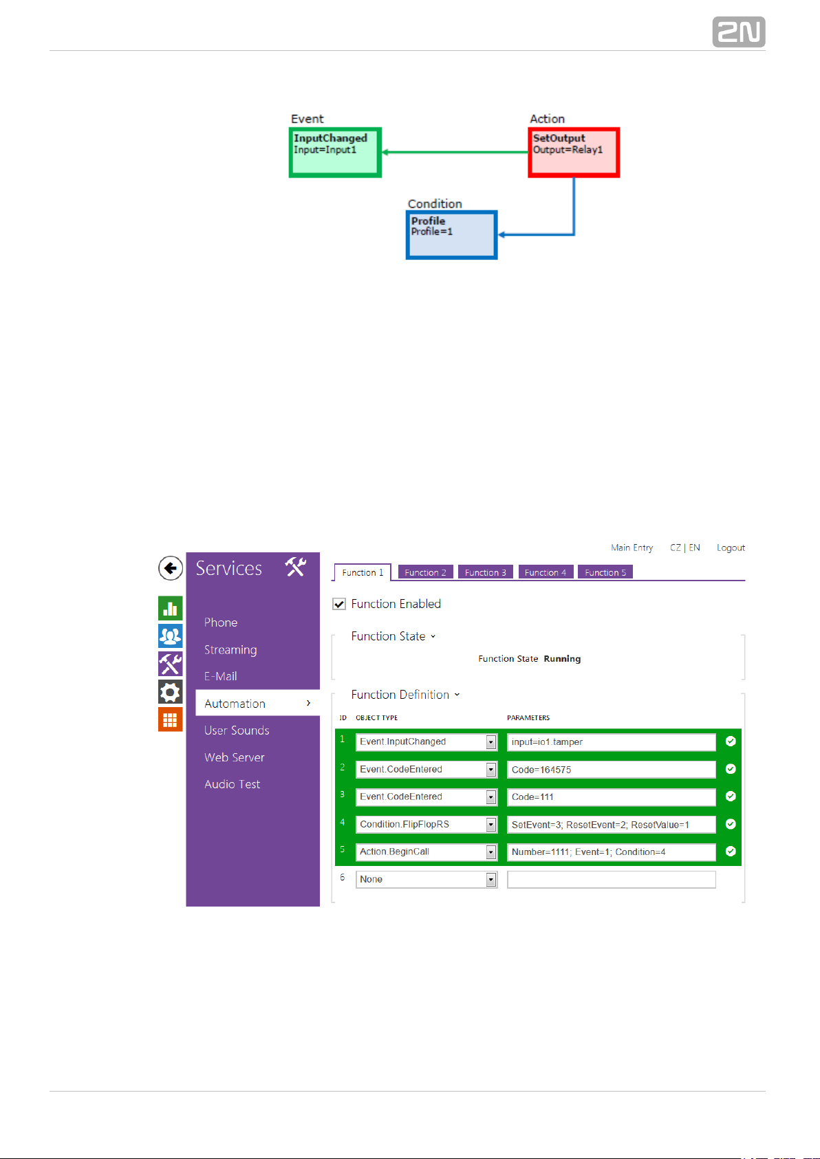
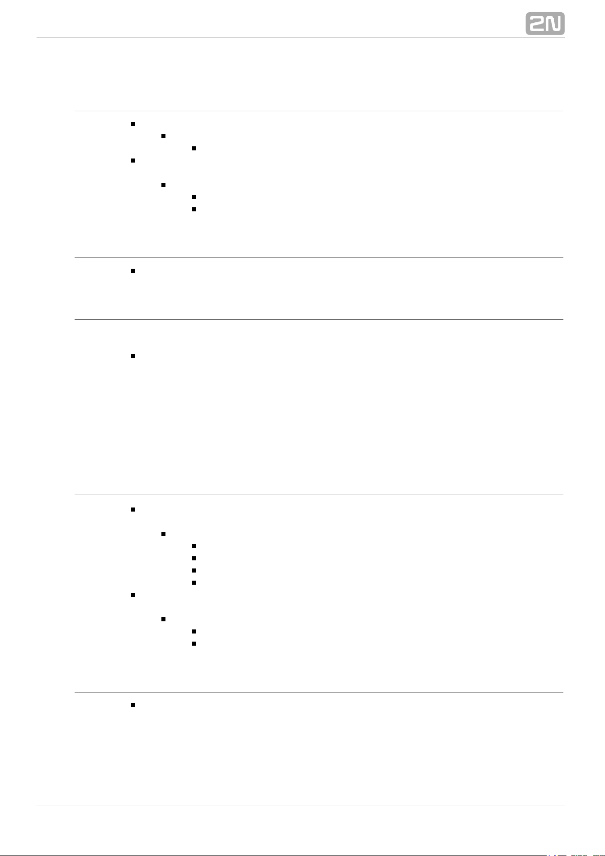
The figure above shows a typical interconnection of the Event, Action and Condition
blocks. It holds true in general that an action is always tied with a selected event and is
executed when a selected condition is met. The condition is optional and if none is
selected, the action is executed whenever the assigned event occurs. 2N Helios IP
®
defines a number of events, actions and conditions to be further set.Automation
Refer to the subsections below for the full list.
The example shown in the figure above can be interpreted as follows: The SetOutput
action (digital output setting) is executed if the event (logic input1InputChanged
change from log 0 to log 1) arises and the (active profile 1) condition is met.Profile
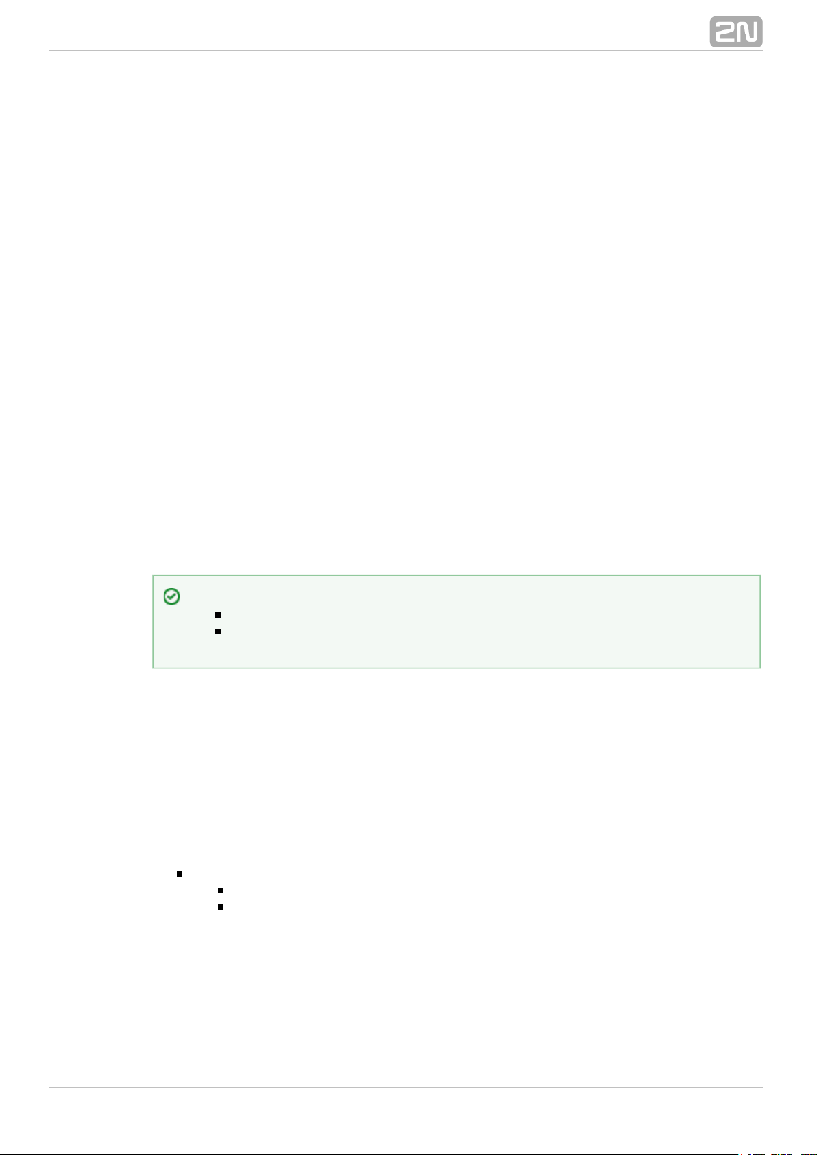
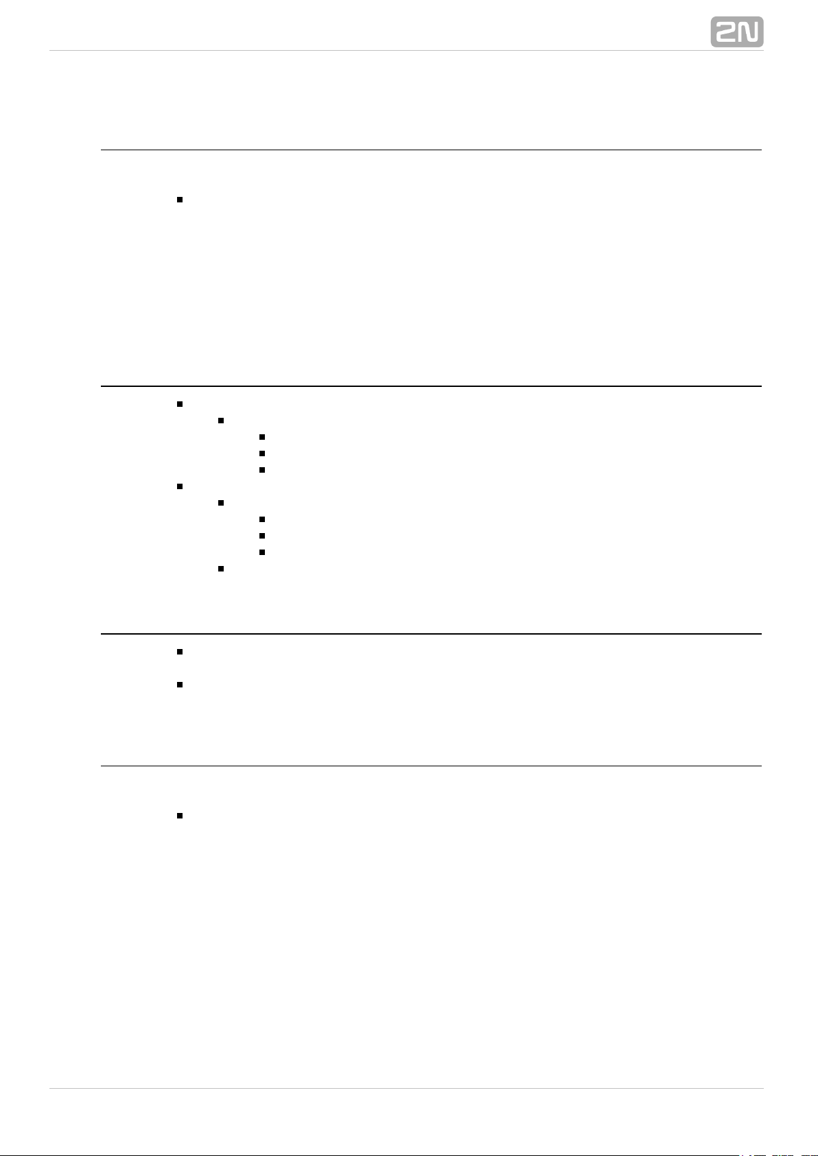
The web interface helps you configure block combinations2N Helios IP
®
(Automation) easily. The configuration shown in the figure below corresponds to the
example above.
2N Helios IP® allows up to 20 blocks at 5 pages to be created and interconnected
(regardless of the block type – events, actions and conditions). Multiple actions can be
assigned to an event or condition. Thus, you can create 10 actions and assign them to
10 events, or create 19 actions and assign them to 1 event, for example.
®
62N TELEKOMUNIKACE a.s., www.2n.cz
Page 7
Block Parameter Settings
Select the required Event (Event.xxx), Action (Action.xxx) or Condition (Condition.xxx)
in the column. Set one or more parameters for the blocks in theObject type
respective row of the column – refer to the block describing subsectionsParameters
below for the supported parameters. Separate the parameters with a colon if more
parameters are required.
The changes will not be executed until you press the button in the right-handSave
bottom corner of the page.
If you have set a parameter correctly, a green mark will appear at the end of the
respective block definition row. If not (if you enter a wrong parameter name/value or
fail to complete an obligatory block parameter), a red mark will appear at the end of
the row. Move your mouse cursor to the red mark to display the Help to find the error.
If all the required blocks have been configured correctly (there is a green mark on
every row), will be enabled. If there is a red mark, the 2N Helios IP Automation
®
function will be disabled.2N Helios IP Automation
®
Most of the blocks include parameters (Event, Condition, StartEvent, e.g.) that refer to
other blocks. Set these parameters to interconnect the defined blocks. Make sure that
the value to be entered matches the row number in the table defining the block that is
referred to. If you enter a wrong value (not matching the defined block type or
matching an undefined block) and press , a red mark will appear at the respectiveSave
row.
Use of Variables
The event block variables (parameters) help transfer additional information between
blocks – send the detected card ID via HTTP to another device, use the parameters
received via HTTP for setting parameters of a tied action and so on. Their values are
updated whenever the event is generated. Use the following syntax to refer to a
variable in the configuration parameters of another block:
$(block_number.variable_name) – the block number and variable name are separated
with a dot.
Example:
1: Event.KeyPressed: Key=Any
2: Action.SendHttpRequest: Event=1; Uri=
http://192.168.1.1/ABCD?Key=$(1.Key)
Press any key (block 1 Event.KeyPressed) to send the HTTP request (block 2
Action.SendHttpRequest) to IP address 192.168.1.1. For example, if you press *, the
HTTP request URI will be as follows: http://192.168.1.1/ABCD?Key=*
Tip
The Upper-Lower case need not be respected in the parameter names.
Some block parameters are optional. If you do not enter an optional
parameter in the block definition, the default value will be applied.
®
72N TELEKOMUNIKACE a.s., www.2n.cz
Page 8
Every event defines the and variables.TimeStamp Count
TimeStamp contains encoded date and time of the last event generation in the Unix
Time format (second count from 00:00:00 1.1.1970).
Count contains the count of event generations after the device start or last block
configuration change. The variable increases by 1 after each event generation.
Refer to the following subsections for more variables with specific functions.
Tip
The Upper/Lower case is not be respected in the variable names.
Caution
You cannot use the variables in the block relation defining parameters, i.e.
Event, Condition, etc.
®
82N TELEKOMUNIKACE a.s., www.2n.cz
Page 9

3. Events
2N Helios IP Automation® defines the following event types:
KeyPressed – key pressed
DtmfPressed – DTMF code received in call
DtmfEntered – DTMF-received in call numeric code detected
CodeEntered – numeric code entered
CardEntered – RFID card entered
CallStateChanged – call state changed
InputChanged – digital input changed
Delay – delay defined
Timer – periodical event timer
HttpTrigger – HTTP command received
MulticastTrigger – command for multiple devices received
AudioLoopTest – audio test performed
See below for details on the events and their parameters and use.
Event.KeyPressed
The block defines the event generated by pressing of the defined key orKeyPressed
any key from the defined group.
®
92N TELEKOMUNIKACE a.s., www.2n.cz
Page 10
Parameters
Key – define the key or a key group. If this parameter is not completed, the
event is generated upon pressing of any key (default value: any).
Valid values:
0, , , , , , , , , , , for numeric keypad buttons1 2 3 4 5 6 7 8 9 * #
%1, , .., for quick dial buttons%2 %999
any for any button (default value).
Separate the values with a comma while defining more keys than one.
SuppressTones – suppress sound signalling initiated by pressing of a
non-programmed quick dial button. The parameter is optional.
Valid values:
0 – tones are not suppressed
1 – tones are suppressed (default value)
Variables
Key – the recorded code of the key which was the last to generate this event.
The key code is stored in the Key parameter format.
Example
Event generated by pressing of # and quick dial button 3 or 4:
Event.KeyPressed: Key=#, %3, %4
Event.DtmfPressed
The block defines the event that is generated when the defined or anyDtmfPressed
DTMF code is received from the defined group. DTMF codes are detected both in
incoming and outgoing calls.
Parameters
Key – define the DTMF code (or DTMF code group). If this parameter is not
completed, the event is generated whenever any DTMF code is detected (default
value: Any).
Valid values:
0, , , , , , , , , , , , , , , 1 2 3 4 5 6 7 8 9 * # A B C D
any for any key (default value).
Separate the values with a comma to specify a group of codes.
Direction – define the call direction.
Valid values:
incoming – incoming calls
outgoing – outgoing calls
any – both directions
The parameter is optional, the default value is .any
®
102N TELEKOMUNIKACE a.s., www.2n.cz
Page 11

Variables
Key – the recorded received DTMF code which was the last to generate the
event. The DTMF is stored in the Key parameter format.
Example
Event generated upon detection of DTMF code #:
Event.KeyPressed: Key=#
Event.DtmfEntered
The block defines the event that is generated by entering of a DTMFDtmfEntered
numeric code confirmed with the * key in an incoming or outgoing call.
Parameters
Code efine the numeric code.– d
Valid values:
numeric code – 12345, e.g.
Variables
Code – the detected received numeric code which was the last to generate this
event.
Example
Event generated upon detection of DTMF code 12345*
Event.DtmfEntered: Code=12345
Event.CodeEntered
The block defines the event generated by entering of a numeric codeCodeEntered
and confirmation with the * key (for numeric keypad models only).
®
112N TELEKOMUNIKACE a.s., www.2n.cz
Page 12
Parameters
Code – define the numeric code.
Valid values:
numeric code – 12345, e.g.
SuppressTones – suppress sound signalling initiated by receiving of an invalid
numeric code. The parameter is optional.
Valid values:
0 – tones are not suppressed
1 – tones are suppressed (default value).
Variables
Code – the received numeric code which was the last to generate this event.
Example
Event generated by entering code 12345* on a keypad:
Event.CodeEntered: Code=12345
Event.CardEntered
The block defines the event generated by tapping (swiping) of the RFIDCardEntered
card with the defined ID (for RFID card reader models only).
Parameters
Card – define the RFID card ID; refer to the Card Reader subsection in the 2N
®
.Helios IP Configuration Manual
Valid values:
valid – any valid card (included in the intercom card list)
invalid – any invalid card
any - any valid or invalid card
card ID - defined card ID e.g. 3F00F34F78.
SuppressTones – suppress sound signalling initiated by detection of an invalid
card. The parameter is optional.
Valid values:
0 – tones are not suppressed
1 – tones are suppressed (default value).
Variables
Card – ID of the detected card which was the last to generate this event.
®
122N TELEKOMUNIKACE a.s., www.2n.cz
Page 13
Example
Event generated by entering of the card with ID 0012456:
Event.CardEntered: Card=0012456
Event.CallStateChanged
The block defines the event generated by a call state change (callCallStateChanged
ringing, call connection, call termination, etc.).
Parameters
State – define the call state change.
Valid values:
ringing – ringing start
connected – successful call connection
terminated – call termination.
Direction – define the call direction.
Valid values:
incoming – incoming calls
outgoing – outgoing calls
any – both directions.
The parameter is optional, the default value is .any
Variables
State – the detected call state which generated this event. The options
correspond to the State parameter.
Direction – the detected call direction which generated this event. The options
are incoming or outgoing.
Example
Event generated by termination of any outgoing call:
Event.CallStateChanged: State=terminated; Direction=outgoing
Event.InputChanged
The block defines the event generated by a change of the logic levelInputChanged
on the defined digital input.
®
132N TELEKOMUNIKACE a.s., www.2n.cz
Page 14

Parameters
Input – define the logic input.
Valid values:
tamper – tamper switch input
input1 – digital input 1
input2 – digital input 2
cr_input1 – digital input 1 on card reader
cr_input2 – digital input 2 on card reader.
There may be different lists of valid values for different 2N Helios IP
®
models; refer to the Available Digital Inputs and Outputs subsection.
Edge – define the detected change on the digital input.
Valid values:
falling – falling edge, change from log. 1 to log. 0
rising – rising edge, change from log. 0 to log. 1.
The parameter is optional, the default value is .rising
Variables
Input – the detected ID of the input whose change was the last to generate this
event. The options correspond to the Input parameter values.
Edge – the detected edge change which was the last to generate this event. The
options are falling or rising.
Example
Event generated by disconnection of the tamper switch (device opening):
Event.InputChanged: Input=tamper
Event.Delay
The block defines the event generated with a defined delay after anotherDelay
specified event. Define this event to delay the response to the other event by a defined
time interval (Delay).
Parameters
StartEvent – define the event that starts the delay.
StopEvent – define the event that stops the delay. The parameter is optional.
Delay – define the delay time.
Example of valid values:
10 – 10 seconds (units are unnecessary)
10s – 10 seconds
100ms – 100 milliseconds.
®
142N TELEKOMUNIKACE a.s., www.2n.cz
Page 15

Variables
This block does not define any specific variables.
Example
Event generated 1s after the rise of event on row 1:
Event.Delay: StartEvent=1; Delay=1s
Event.Timer
The block defines the event generated with a defined delay after anotherTimer
specified event with a defined count of repetitions. Define this event to delay the
response to the other event by a defined time interval, or execute the response several
times.
Parameters
StartEvent – define the timer starting event (i.e. the row number in the
Automation tag on which the event is defined). The parameter is optional. If no
value is completed, the timer will be started automatically.
StopEvent – define the timer stopping event (i.e. the row number in the
Automation tag on which the event is defined). When StopEvent is executed, the
timer will stop and will be restarted by StartEvent only. This parameter is
optional.
Period – define the timer period.
Example of valid values:
10 – 10 seconds (units are unnecessary)
10s – 10 seconds
100ms – 100 milliseconds.
Count – define the count of repetitions. The parameter is optional and the
default value is 0, which means that the count of timer generated events is
unlimited. Value 1 makes the timer behave as a Delay.
Variables
This block does not define any specific variables.
Example
Event generated three times in 1s intervals after the rise of event on row 1:
Event.Timer: StartEvent=1; Period=1s; Count=3
®
152N TELEKOMUNIKACE a.s., www.2n.cz
Page 16

Event.HttpTrigger
The block defines the event generated by receiving of an HTTP commandHttpTrigger
from the intercom HTTP server. When the HTTP command http://ip_addr/enu/trigger/i
is received, the event will be generated whose ID matches the value that followsd
'trigger/' in the HTTP command. The intercom sends a simple reply to this request (200
OK).
Parameters
Name – define a unique HTTP command identifier including alphabetical
characters and digits.
Variables
The HttpTrigger event is always generated by the HTTP command which can carry a list
of user parameters as included in the URI command.
http://ip_address/enu/trigger/id?param1=value1¶m2=value2
The list of parameters follows the ? character. Each parameter must include the name
and value separated with the = character. If the list includes more parameters than
one, & is used as the separator.
The HTTP-received parameters are available as HttpTrigger block variables. The
variable name equals to the name of the parameter transferred - $(line.param1) a
$(line.param2)
Example
Event generated by receiving of the following HTTP command: http://ip_addr/enu/trigg
:er/opendoor
Event.HttpTrigger: Name=opendoor
Event.MulticastTrigger
The MulticastTrigger block defines the event generated by receiving of a command sent
via SendMulticastRequest. The request is a message sent by UDP to a multicast
address (235.255.255.250:4433) and can thus be received by multiple devices at the
same time. The message includes the command ID (Command parameter) and
additional optional parameters. The message can be password-secured (Password
parameter).
®
162N TELEKOMUNIKACE a.s., www.2n.cz
Page 17

Parameters
Command efine the command ID to distinguish the command types. The– d
MulticastTrigger block responds to the SendMulticastRequest action only if the
command identifier is the same. Any text containing the A-Z, a-z and 0-9
characters can be used for identification. The Upper/Lower case must be
respected in the command name.
Password efine the password to secure the command against unauthorised– d
access. The password must match the value defined in the SendMulticastRequest
action to which MulticastTrigger is expected to respond.
CheckTime nable/disable the check of the command receiving time against– e
the time value included in the command message to eliminate attacks caused by
repeating of an already processed message. Synchronised time (via the NTP
server) on all command sending and receiving devices is required for this
function.
Valid values:
0 – message time is not checked
1 – message time is checked (enhanced security).
The parameter is optional, the default value is .0
Variables
The MulticastTrigger event is generated whenever a mass command including the list
of user parameters (Params parameter, MulticastRequest action) is received. Each of
the parameters has a user-defined unique name and is available as a variable of the
same name in the MulticastTrigger block.
Example: Suppose a mass command generated by the MulticastRequest action is
received, in which Params=“AAA=123” is included. The MulticastTrigger event which
processes this command will automatically include value 123 for the AAA variable. This
variable can be referred to in the interconnected blocks.
Example
Event generated by receiving of a mass opendoor command:
Event.MulticastTrigger: Command=opendoor
Event.AudioLoopTest
The block defines the event generated after the loudspeaker andAudioLoopTest
microphone test (Audio Loop Test) is performed. The subsequent actions are executed
based on the test result.
®
172N TELEKOMUNIKACE a.s., www.2n.cz
Page 18

Parameters
Result – this parameter specifies the required test result.
Valid values:
any – the event is generated whenever the test is performed
(regardless of the result).
passed – the event is generated whenever the test is successful.
failed – the event is generated whenever the test fails.
The parameter is optional, the default value is .failed
Variables
This block does not define any specific variables.
Example
An event generated after the audio loop test if the test result is negative (i.e. the
microphone or loudspeaker is out of order):
Event.AudioLoopTest: Result=failed
®
182N TELEKOMUNIKACE a.s., www.2n.cz
Page 19

4. Actions
2N Helios IP Automation® – defines the following types of actions:
ActivateSwitch – switch activation
SetOutput – digital output state setting
BeginCall – outgoing call setup
AnswerCall – incoming call answer
EndCall – call termination
SendHttpRequest – HTTP command sending
SendMulticastRequest – command sending to multiple devices
PlayUserSound – user sound playing
StartMulticastSend – audio stream sending start
StopMulticastSend – audio stream sending stop
StartMulticastRecv – audio stream receiving start
StopMulticastRecv – audio stream receiving stop
SetCameraInput – camera input selection
ControlRtpStream – call RTP stream control
LogEvent – event logging to the syslog server
SendEmail – email sending
Action.ActivateSwitch
The block defines the action necessary for activation of the intercomActivateSwitch
switch as configured in the Switch 1–4 tags. The activity to be performed depends fully
on the particular switch settings (digital output activation, HTTP command sending,
etc.). Switch deactivation is controlled by the switch settings too.
Parameters
Event – define the event to launch the action.
Condition – define the condition to be met to execute the action. This parameter
is optional.
Switch – define the switch to be activated (1 to 4).
®
192N TELEKOMUNIKACE a.s., www.2n.cz
Page 20

Example
Activate switch 1 if the event defined on row 2 arises and the condition defined on row
3 is met:
Action.ActivateSwitch: Switch=1; Event=2; Condition=3
Action.SetOutput
The block defines the action necessary for setting of the intercom output toSetOutput
the required level.
Parameters
Event – define the event that launches the action.
Condition – define the condition to be met to execute the action. This parameter
is optional.
Output – define the output to be set.
Valid values:
relay1 – relay 1 on basic unit
relay2 – relay 2 on basic unit
output1 – output 1 on basic unit
output2 – output 2 on basic unit
cr_relay1 – relay 1 on card reader
cr_relay2 – relay 2 on card reader
cr_output – output 1 on card reader
redled – red LED indicator
led1 – LED 1 indicator
led2 – LED 2 indicator
led3 – LED 3 indicator.
There may be different lists of valid values for different 2N Helios IP
®
models; refer to the Available Digital Inputs and Outputs subsection.
Level – define the required output level. This parameter is optional.
Valid values:
0 – output deactivation
1 – output activation (default value).
Example
Activate Output1 if the event defined on row 2 arises:
Action.SetOutput: Output=output1; Event=2
Action.BeginCall
The block defines the action necessary for establishing of an outgoing call toBeginCall
the defined telephone number, SIP URI or user number included in the intercom phone
book.
®
202N TELEKOMUNIKACE a.s., www.2n.cz
Page 21

Parameters
Event – define the event to launch the action.
Condition – define the condition to be met to execute the action. This parameter
is optional.
Number – define the phone number to be called.
Uri – define the SIP URI to be called: sip:user@domain
User – define the phone book number to be called. The valid values are 1
through 999 (depending on the intercom model).
Enter just one of the above mentioned parameters ( , or ).Number Uri User
Example
Establish an outgoing call if the event defined on row 2 arises:
Action.BeginCall: Number=1001; Event=2
Action.AnswerCall
The block defines the action necessary for answering of an incoming call.AnswerCall
In case no call is coming or the incoming call is not ringing, the action will not initiate
any activity.
Parameters
Event – define the event to launch the action.
Condition – define the condition to be met to execute the action. This parameter
is optional.
Example
Answer a call if the event defined on row 2 arises:
Action.AnswerCall: Event=2
Action.EndCall
The block defines the action necessary for termination of the currently madeEndCall
call. In case there is no active call via the intercom, the action will not initiate any
activity.
Parameters
Event – define the event to launch the action.
Condition – define the condition to be met to execute the action. This parameter
is optional.
®
212N TELEKOMUNIKACE a.s., www.2n.cz
Page 22

Example
Terminate a call if the event defined on row 2 arises:
Action.EndCall: Event=2
Action.SendHttpRequest
The block defines the action necessary for sending of an HTTPSendHttpRequest
command to another LAN device. The HTTP command helps you control other devices
in the LAN (IP relay, recording system, another intercom, etc.).
Parameters
Event – efine the event to launch the action. d
Condition – define the condition to be met to execute the action. This parameter
is optional.
Uri – define the standard HTTP URI including the destination address and,
optionally, the path and other parameters.
Example
Send an HTTP command to the device with the IP address 192.168.1.1 if the event
defined on row 2 arises:
Action.SendHttpRequest: uri= ; Event=2http://192.168.1.1/message
Action.SendMulticastRequest
The block defines the action necessary for user commandSendMulticastRequest
sending to multiple devices. The sent command can be processed by the
MulticastTrigger block. The command is a message sent by UDP to a multicast address
(235.255.255.250:4433) and can thus be received by multiple devices at the same
time. The message includes the command ID (Command parameter) and additional
optional parameters (Params parameters). The message can be password-secured
(Password parameter).
®
222N TELEKOMUNIKACE a.s., www.2n.cz
Page 23

Parameters
Event – define the event to execute this action.
Condition – define the condition to be met for the action to be executed. This
parameter is optional.
Command – define the command identifier to distinguish the command types.
The MulticastTrigger block responds to the SendMulticastRequest action only if
the command identifier is the same. Any text containing the A–Z, a–z and 0–9
characters can be used for identification.
Params – define one or more (comma-separated) command parameters to be
included in the UDP message. Keep the “parameter_name=parameter_value”
format.
Example:
Params=“Address=192.168.1.1”, “Port=10000”
The so-sent parameters will be available in the HttpTrigger event responding
to this command as the Address and Port variables and can be used in
HttpTrigger-tied actions, for example.
Password efine the password to secure the command against unauthorised– d
access. The parameter is optional. If no password is completed, the command is
not secured. Use any text containing the A–Z, a–z and 0–9 characters.
Example
Send the opendoor command to all devices with the properly set Event.MulticastTrigger
block in the network if the event defined on row 2 arises:
Action.SendMulticastRequest: Command=opendoor; Event=2
Action.PlayUserSound
The block defines the user sound playing action.PlayUserSound
Parameters
Event efine the event to launch this action.– d
Condition efine the condition to be met for the action to be executed. This– d
parameter is optional.
Sound elect the user sound number (1 – 10).– s
Destination – define the user sound playing destination.
Valid values:
Speaker – the sound is played on the intercom.
Call – the sound is played into the call.
The parameter is optional, the default value is .Speaker
®
232N TELEKOMUNIKACE a.s., www.2n.cz
Page 24

Example
Play user sound 1 if the event defined on row 2 arises:
Action.PlayUserSound: Sound=1; Event=2
Action.StartMulticastSend
The block defines the starting action for audio stream sending toStartMulticastSend
a multicast IP address. You can control up to four independent transmission channels.
The RTP/UDP protocol is used and the data are in the PCMU format.
Parameters
Event efine the event to launch this action.– d
Condition efine the condition to be met for the action to be executed. This– d
parameter is optional.
Channel efine the channel number (1–4) to be controlled.– d
Address efine the audio stream multicast IP address.– d
Port efine the UDP port to which audio stream shall be sent.– d
Example
Start audio stream sending via channel 1 to address 239.0.0.1:10000 if the event
defined on row 2 arises:
Action.StartMulticastSend: Channel=1; Address=239.0.0.1; Port=1000; Event=2
Action.StopMulticastSend
The block defines the stopping action for audio stream sending to StopMulticastSend
a multicast IP address.
Parameters
Event – define the event to launch this action.
Condition – define the condition to be met for the action to be executed. This
parameter is optional.
Channel – define the channel number (1–4) to be controlled.
Example
Stop audio stream sending via channel 1 if the event defined on row 2 arises:
Action.StopMulticastSend: Channel=1; Event=2
®
242N TELEKOMUNIKACE a.s., www.2n.cz
Page 25

Action.StartMulticastRecv
The block defines the starting action for audio stream receivingStartMulticastRecv
and playing. You can control up to four independent transmission channels. The
RTP/UDP protocol is used and the data are in the PCMU format.
Parameters
Event – define the event to launch this action.
Condition – define the condition to be met for the action to be executed. This
parameter is optional.
Channel – define the channel number (1–4) to be controlled.
Address – define the audio stream multicast IP address.
Port – define the UDP port on which audio stream shall be received.
Volume – define the relative volume level for the audio stream to be played
(from −6dB to +6dB).
Valid values:
6− – minimum level
0 – mean level (default value)
6 – maximum level.
The parameter is optional, the default value is .0
Example
Start audio stream receiving on multicast IP address 239.0.0.1:10000 via channel 1 if
the event defined on row 2 arises:
Action.StartMulticastRecv: Chanel=1; Address=239.0.0.1; Port=10000
Action.StopMulticastRecv
The block defines the stopping action for audio stream receivingStopMulticastRecv
to a multicast IP address.
Parameters
Event – define the event to launch this action.
Condition – define the condition to be met for the action to be executed. This
parameter is optional.
Channel – define the channel number (1–4) to be controlled.
Example
Stop audio stream receiving via channel 1 if the event defined on row 2 arises:
Action.StopMulticastRecv: Channel=1
®
252N TELEKOMUNIKACE a.s., www.2n.cz
Page 26

Action.SetCameraInput
The block defines the action that switches the video signal sources –SetCameraInput
either the integrated video camera or an external IP camera, or two inputs for
analogue camera connection to the .2N Helios IP Video Kit
®
Parameters
Event – define the event to launch this action.
Condition – define the condition to be met for the action to be executed. This
parameter is optional.
Type – define the video signal type. A change during a call will apply only for this
call. Other video receivers receive video from the same source.
Valid values:
internal – internal camera (or external analogue video camera
connected directly to the device)
external – external IP camera.
The parameter is optional, the default value is .internal
Id – define the video signal channel. The parameter is available with the 2N
®
Helios IP Video Kit model only and applicable only if the Type parameter is set to
.internal
Valid values:
1 – analogue camera connected to input 1
2 – analogue camera connected to input 2
The parameter is optional, the default value is .1
Example
Switch the video signal source to the first external analogue camera input if the event
defined on row 2 arises:
Action.SetCameraInput: Type=internal; Id=1; Event=2
Action.ControlRtpStream
Block defines the action that controls the flow of the RTP streams. ControlRtpStream
This action controls only call streams; multicast streams are not affected by this action.
®
262N TELEKOMUNIKACE a.s., www.2n.cz
Page 27

Parameters
Event – define the event to launch this action.
Condition – define the condition to be met for the action to be executed. This
parameter is optional.
Direction – define the call RTP stream playing direction.
Valid values:
in – incoming stream to the intercom
out – outgoing stream from the intercom
both – incoming and outgoing stream.
The parameter is optional, the default value is . both
– define the RTP stream operation.Operation
Valid values
mute – mute the stream
unmute – unmute the stream (stream is played).
Example
Mute call streams in both ways : if the event defined on row 2 arises
Action.ControlRtpStream: Direction=both; Operation=mute; Event=2
Action.LogEvent
The block defines the action that logs the event to the syslog server. This LogEvent
block can be used for verification of Automation settings.
Parameters
Event – define the event to launch this action.
Condition – define the condition to be met for the action to be executed. This
parameter is optional.
Example
Send a syslog message with captured event 2 (Event.CardEntered) if the event defined
:on row 2 arises
Action.LogEvent: Event=2
Sent syslog message format:
LOCAL0.DEBUG: Jan 10 12:49:14.305 ACT: aut_action_logevent_callback():
Logged event 'CardEntered'
®
272N TELEKOMUNIKACE a.s., www.2n.cz
Page 28

Action.SendEmail
The block defines the action that sends an email. The email parameters are SendEmail
configured in the Services / E-Mail menu.
Parameters
Event – define the event to launch this action.
Condition – define the condition to be met for the action to be executed. This
parameter is optional.
User – define the user to whom the email will be sent.
Valid values:
user_position – numeric value of the user phone book position.
Email – define the email address to which the email will be sent.
Valid values:
user@domain_name, user@ip_address
Example
Send an email to the email address defined for the user in book phone position 5 if the
:event defined on row 2 arises
Action.SendEmail: User=5; Event=2
Tip
The parameter has a preference before the parameter .User Email
®
282N TELEKOMUNIKACE a.s., www.2n.cz
Page 29

5. Conditions
2N Helios IP Automation® defines the following types of conditions:
ProfileState – time profile state
CallState – current call state
InputState – digital input state
LogicalAnd – logical AND of conditions
LogicalOr – logical OR of conditions
LogicalNot – condition negation
True – always true condition
False – always false condition
FlipFlopD – D-type flip-flop
FlipFlopRS – RS-type flip-flop
See below for details on the conditions and their parameters and use.
Condition.ProfileState
The block defines the condition to be met in the case of active/inactiveProfileState
time profile.
Parameters
Profile – define the time profile number (1–20 depending on the intercom
model).
State – define the required profile state. This parameter is optional.
Valid values:
active – active profile (default value)
inactive – inactive profile.
Example
The condition is met for inactive time profile 1:
Condition.ProfileState: Profile=1; State=Inactive
®
292N TELEKOMUNIKACE a.s., www.2n.cz
Page 30

Condition.CallState
The block defines the condition to be met in the case of a defined state ofCallState
the currently made call.
Parameters
State – define the call state.
Valid values:
idle – call is not being made
connecting call setup in progress–
ringing – ringing in progress
connected – call connected.
Direction – define the call direction.
Valid values:
incoming – incoming calls
outgoing – outgoing calls
any – both directions.
The parameter is optional, the default value is .any
Example
The condition is met for an inactive call:
Condition.CallState: State=Idle
Condition.InputState
The block defines the condition to be met in case the defined logic levelInputState
gets connected to the defined digital input.
Parameters
Input – define the digital input.
Valid values:
tamper – tamper switch
input1 – digital input 1
input2 – digital input 2
cr_input1 – digital input 1 on card reader
cr_input2 – digital input 2 on card reader.
There may be different lists of valid values for different 2N Helios IP
®
models; refer to the Available Digital Inputs and Outputs subsection.
Level – define the required digital input level. The parameter is optional.
Valid values:
0 – logic 0
1 – logic 1 (default value).
®
302N TELEKOMUNIKACE a.s., www.2n.cz
Page 31

Example
The condition is met for an activated tamper switch (device not open):
Condition.InputState: Input1=tamper; Level=0
Condition.LogicalAnd
The block helps you create groups of conditions. The block is fulfilled if allLogicalAnd
the conditions in the defined group are met.
Parameters
Condition – define the list of conditions to be met. Separate the conditions with
a comma.
Example
The condition is met if conditions 1, 2 and 3 are met at the same time:
Condition.LogicalAnd: Condition=1, 2, 3
Condition.LogicalOr
The block helps you create groups of conditions. The block is fulfilled if oneLogicalOr
condition at least of the defined group is met.
Parameters
Condition – define the list of conditions to be met. Separate the conditions with
a comma.
Example
The condition is met if conditions 1, 2 or 3 are met:
Condition.LogicalOr: Condition=1, 2, 3
Condition.LogicalNot
The block defines the condition to be met in case another defined conditionLogicalNot
is not met.
®
312N TELEKOMUNIKACE a.s., www.2n.cz
Page 32

Parameters
Condition – define the condition not to be met.
Example
The condition is met in case condition 1 is not met:
Condition.LogicalNot: Condition=1
Condition.True
The block defines the condition to be met each time.True
Parameters
There are no parameters in the True block.
Example
The condition is always met:
Condition.True
Condition.False
The block defines the condition not to be met any time.False
Parameters
There are no parameters in the False block.
Example
The condition is always not met.
Condition.False
®
322N TELEKOMUNIKACE a.s., www.2n.cz
Page 33

Condition.FlipFlopD
The block is a one-bit memory cell (variable), which records the state ofFlipFlopD
another condition at the moment of rise of the defined event for later use. The
FlipFlopD output can be used as a condition for action control in rather complex 2N
®
applications. It is a simulation of a D-type flip-flop circuit.Helios IP Automation
Parameters
ClockEvent – define the event during which the current state of the condition is
to be recorded.
Condition – define the condition to be recorded at the rise of the ClockEvent.
ResetValue – set the condition default value upon restart. The parameter is
optional.
Valid values:
0 – condition is not met (default value)
1 – condition is met.
Example
The state of the condition is identical with the state of condition 2 at the rise of event
1:
Condition.FlipFlopD: ClockEvent=1; Condition=2
Condition.FlipFlopRS
The block is a one-bit memory cell (variable), whose state changes to 1 orFlipFlopRS
0 at the rise of defined events. The FlipFlopRS output can be used as a condition for
action control in rather complex applications. It is a2N Helios IP Automation
®
simulation of an RS-type flip-flop circuit.
Parameters
SetEvent – define the event to set the condition into the 'met' state (1).
ResetEvent – define the event to set the condition into the 'not met' state (0).
ResetValue – set the condition default value upon restart. The parameter is
optional.
Valid values:
0 – condition is not met (default value)
1 – condition is met.
Example
The condition is met at the rise of event 1 and not met at the rise of event 2:
Condition.FlipFlopRS: SetEvent=1; ResetEvent=2
®
332N TELEKOMUNIKACE a.s., www.2n.cz
Page 34

6. Available Digital Inputs and Outputs
In this section, the digital inputs and outputs available on each model2N Helios IP
®
are described.
2N Helios IP Vario®
2N Helios IP Force/Safety®
2N Helios IP Audio/Video Kit®
2N Helios IP Verso®
2N SIP Speaker®
2N Helios IP Vario
®
Outputs
relay1 – relay output on basic unit
relay2 – relay output on additional switch (if installed)
cr_relay1 – relay output 1 on card reader (if installed)
cr_relay2 – relay output 2 on card reader (if installed)
redled – red LED indicator under name tags (for display-less 9137xxxU models
only)
Inputs
cr_input1 – digital input 1 on card reader (if installed)
cr_input2 – digital input 2 on card reader (if installed)
®
342N TELEKOMUNIKACE a.s., www.2n.cz
Page 35

2N Helios IP Force/Safety
®
Outputs
relay1 – relay output on basic unit
output1 – active digital output on basic unit (for board version 555v3 and
higher, active digital output is connected with relay output 1 in 555v2 boards)
relay2 – relay output on additional switch (if installed)
output2 – active digital output on additional switch (if installed)
cr_relay1 – relay output on card reader (if installed)
cr_output1 – active digital output on card reader (if installed)
led_secured – red LED indicator on card reader (if installed)
led_ringing – orange LED indicator of ringing (for ) models with pictograms only
led_connected – blue LED indicator of connected call (for models with
)pictograms only
led_door – green LED indicator of door opening (for models with pictograms
only)
led_key1 – first button backlight at Safety
led_key2 – second button backlight at Safety
led_key3 – third button backlight at Safety
Inputs
tamper – tamper switch (if installed)
cr_input1 – digit input 1 on card reader (if installed)
cr_input2 – digital input 2 on card reader (if installed)
2N Helios IP Audio/Video Kit
®
Outputs
relay1 – relay output
output1 – digital output 1
output2 – digital output 2
led1 – LED 1 control output
led2 – LED 2 control output
led3 – LED 3 control output
Inputs
input1 – digital input 1
input2 – digital input 2
®
352N TELEKOMUNIKACE a.s., www.2n.cz
Page 36

2N Helios IP Verso
®
Basic Unit
Outputs
out1 - digital output
relay1 - relay output
Inputs
in1 – digital input on basic unit
I/0 Module
Th e in p u ts / o utp u ts are addr e ssed as fol l o ws:
, e.g. module5.relay1.<module_name>.<input/output_name>
The module name is configured in the Hardware /Module name parameter in the
Extenders menu.
Outputs
relay1 - 1relay output
relay2 - 2relay output
Inputs
in1 – 1digital input
in2 – 2digital input
tamper – tamper switch (if installed)
Wiegand Module
The input is addressed as follows: <module_name>.<input_name>, e.g.
module2.tamper
The module name is configured in the Module name parameter in the Hardware /
.Extenders menu
Inputs
tamper – tamper switch (if installed)
®
362N TELEKOMUNIKACE a.s., www.2n.cz
Page 37

2N SIP Speaker
®
Outputs
relay1 – relay output
Inputs
Unavailable
®
372N TELEKOMUNIKACE a.s., www.2n.cz
Page 38

7. Examples of Use
Calling to Dispatching Office in Case of Unauthorised
Door Opening
Specification
Call the selected telephone number whenever the tamper switch gets disconnected
(device opened).
Block diagram
The rising edge on the tamper input (1: Event.InputChanged) initiates calling to the
defined telephone number (2: Action.BeginCall).
Intercom settings
1: Event.InputChanged: Input=tamper
2: Action.BeginCall: Number=1111; Event=1
®
382N TELEKOMUNIKACE a.s., www.2n.cz
Page 39

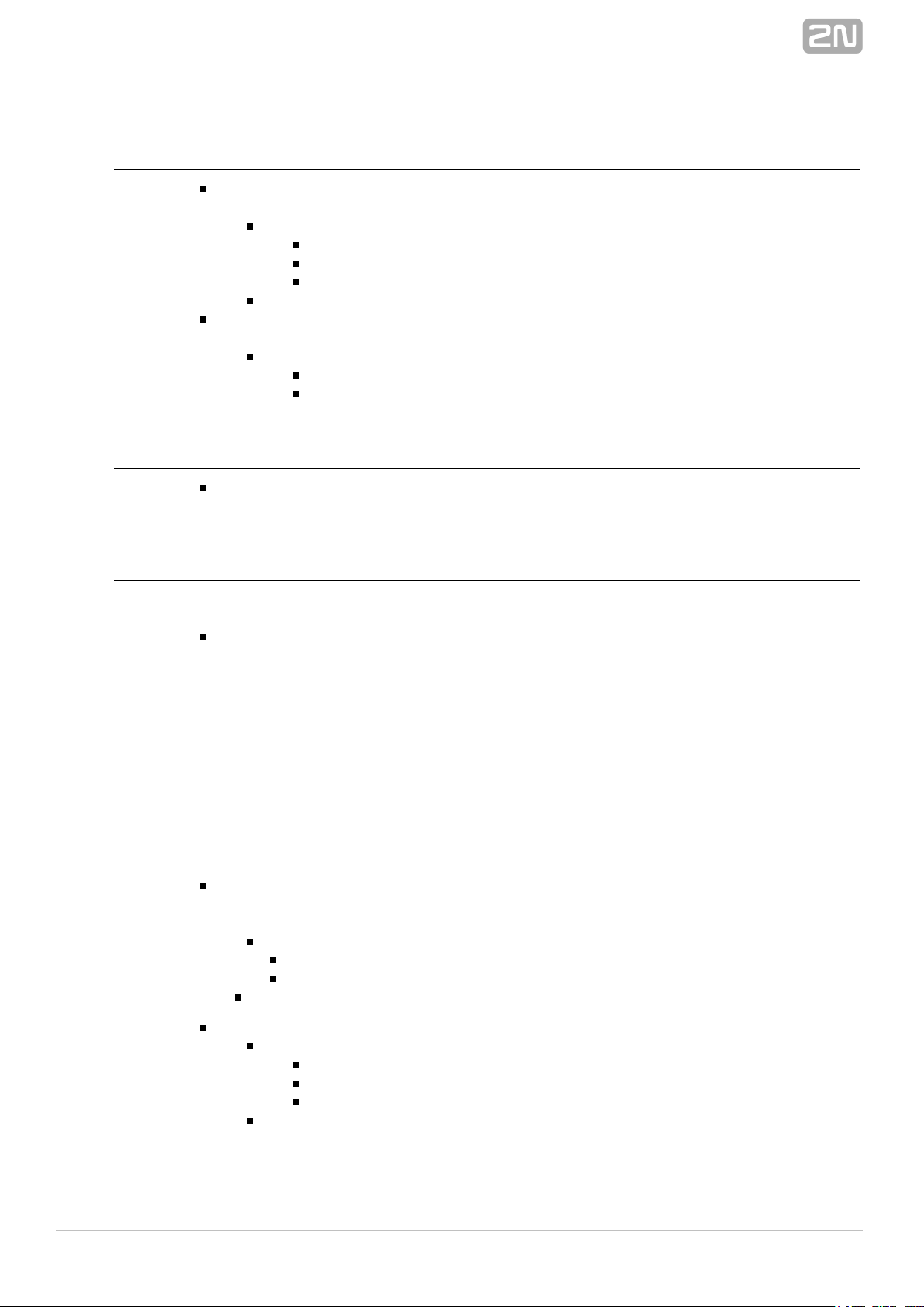
Calling to Dispatching Office in Case of Unauthorised
Door Opening with Service Code Blocking Option
Specification
Call the selected telephone number whenever the tamper switch gets disconnected
(device opened). Enable blocking and re-enable numeric code alarm entered from the
intercom keypad.
Block diagram
The rising edge on the tamper input (1: Event.InputChanged) initiates calling to the
defined telephone number (5: Action.BeginCall) in case the defined condition is met.
The condition (4: Condition.FlipFlopRS) is validated by the intercom restart or entering
the selected code (2: Condition.CodeEntered) on the numeric keypad. If another code
is entered (3: Condition.CodeEntered), the condition will be invalid.
Intercom settings
1: Event.InputChanged: Input=tamper; Edge=rising
2: Event.CodeEntered: Code=164575
3: Event.CodeEntered: Code=111
4: Condition.FlipFlopRS: SetEvent=3; ResetEvent=2; ResetValue=1
5: Action.BeginCall: Number=1111; Event=1; Condition=4
®
392N TELEKOMUNIKACE a.s., www.2n.cz
Page 40

Door Opening by RFID Card
Specification
Activate the door contact switch by tapping/swiping the proper RFID card on/through
the reader.
Block diagram
Entering an RFID card with the defined ID (1: Event.CardEntered) activates switch 1
(2: Action.ActivateSwitch).
Intercom settings
1: Event.CardEntered: Card=0*0000
2: Action.ActivateSwitch: Switch=1; Event=1
Alarm (Dispatching Office Call) Caused by Over 2-Min
Long Door Opening
Specification
Call the dispatching office in case the door remains open for more than 2 minutes. It is
supposed that the door opening signalling contact is connected to Input1.
Block diagram
Whenever the door opens, the rising edge on Input1 signal (1: Event.InputChanged)
calls the defined telephone number (4: Action.BeginCall) with a 120s delay (2:
Event.Delay).The call is only executed if the door remains open for more than 120 s (3:
Condition.InputState).
®
402N TELEKOMUNIKACE a.s., www.2n.cz
Page 41

Intercom settings
1: Event.InputChanged: Input=input1; Edge=rising
2: Event.Delay: Delay=120 s; StartEvent=1
3: Condition.InputState: Input=input1; Level=1
4: Action.BeginCall: Number=1111; Event=2; Condition=3
LED Flashing during Call / Electric Door Lock
Opening
Specification
Enable LED flashing during an active call.
Block diagram
Enable LED flashing by a combination of the periodic timer (1: Event.Timer) and delay
(2: Event.Delay). These two blocks define the period (250 ms) and duty cycle of the
signal or the LED shining period (125 ms). These two events are tied with the
on-switching (4: Action.SetOutput) and off-switching (5: Action.SetOutput) actions.
The LED switch-on action is conditioned by the active call (3: Condition.CallState).
®
412N TELEKOMUNIKACE a.s., www.2n.cz
Page 42

Intercom settings
1: Event.Timer: Period=250 ms
2: Event.Delay: Delay=125 ms; StartEvent=1
3: Condition.CallState: State=Connected
4: Action.SetOutput: Output=led1; Level=1; Event=1; Condition=3
5: Action.SetOutput: Output=led2; Level=0; Event=2
®
422N TELEKOMUNIKACE a.s., www.2n.cz
Page 43

2N TELEKOMUNIKACE a.s.
Modřanská 621, 143 01 Prague 4, Czech Republic
Phone: +420 261 301 500, Fax: +420 261 301 599
E-mail: sales@2n.cz
Web: www.2n.cz
1911v1
®
432N TELEKOMUNIKACE a.s., www.2n.cz
 Loading...