

Page 1
User Manual
Version 1.11.0
Firmware 1.11.x www.2n.cz
®
2N
Door Access Communicator
Helios IP
Page 2

The 2N TELEKOMUNIKACE a.s. joint-stock company is a Czech manufacturer and supplier
of telecommunications equipment.
The product family developed by 2N TELEKOMUNIKACE a.s. includes GSM gateways,
private branch exchanges (PBX), and door and lift communicators.
2N TELEKOMUNIKACE a.s. has been ranked among the Czech top companies for years
and represented a symbol of stability and prosperity on the telecommunications market
for almost two decades. At present, we export our products into over 120 countries
worldwide and have exclusive distributors on all continents.
2N® is a registered trademark of 2N TELEKOMUNIKACE a.s.. Any product and/or other
names mentioned herein are registered trademarks and/or trademarks or brands
protected by law.
Declaration of Conformity
2N TELEKOMUNIKACE a.s. hereby declares that the 2N® Helios IP product complies with
all basic requirements and other relevant provisions of the 1999/5/EC directive. For the
full wording of the Declaration of Conformity see the CD-ROM enclosed and at www.2n.cz.
The 2N TELEKOMUNIKACE company is a holder of the ISO 9001:2000 certificate. All
development, production and distribution processes of the company are managed by this
standard and guarantee a high quality and advanced technical level of and a professional
approach to all of our products.
Page 3

Contents
1. Product Overview............................................................... 7
1.1 Product Description ....................................................................................................... 8
Basic Features.................................................................................................................. 8
Advantages of Use ........................................................................................................... 8
Optional Accessories ........................................................................................................ 9
1.2 2N® Helios IP Components and Associated Products ............................................. 10
Basic Units ...................................................................................................................... 10
Extending modules ......................................................................................................... 11
Extenders ....................................................................................................................... 11
Software Facilities of 2N® Helios IP Basic Units ............................................................ 12
Mounting Accessories .................................................................................................... 13
Increased Resistance Accessories ................................................................................ 15
GSM and UMTS Connection Accessories ..................................................................... 15
VoIP Connection Accessories ........................................................................................ 16
Electric Locks ................................................................................................................. 16
Other Accessories .......................................................................................................... 16
1.3 Terms and Symbols Used ........................................................................................... 17
Manual Symbols ............................................................................................................. 17
2. Description and Installation ............................................ 19
2.1 Before You Start ........................................................................................................... 20
Product Completeness Check ........................................................................................ 20
2.2 Mounting – Mechanical Installation ............................................................................ 21
Overview of Installation Types ....................................................................................... 21
Surface Mounting ........................................................................................................... 22
Flush Mounting ............................................................................................................... 26
Increased Resistance Version Installation ..................................................................... 26
2.3 Mounting – Electrical Installation ............................................................................... 27
Description of Printed Circuit Board Connectors ............................................................ 27
Configuration Connector Connection ............................................................................. 33
Display Connector .......................................................................................................... 33
2.4 Mounting - Completion ................................................................................................ 35
Most Frequent Mounting Errors...................................................................................... 35
2.5 Extending Module Connection .................................................................................... 37
Maximum Count of Extenders ........................................................................................ 37
Module Cable Interconnection........................................................................................ 38
Button Numbering .......................................................................................................... 39
Button Numbering – Info Panel Sets .............................................................................. 40
Page 4

3. 2N® Helios IP Configuration ............................................ 41
3.1 Acoustic Signalling and Keypad Configuration ........................................................ 42
Tone Signalling ............................................................................................................... 42
Switching to Default Network Parameters – Static IP Address ...................................... 43
Switching to Default Network Parameters – Dynamic IP Address ................................. 45
Web Server Switch On ................................................................................................... 46
3.2 Quick Configuration for Calling .................................................................................. 48
Language Selection ........................................................................................................ 48
Network Settings ............................................................................................................ 48
Static Parameter Setting ................................................................................................ 48
SIP Parameter Setting .................................................................................................... 49
Telephone Directory Setting ........................................................................................... 50
Lock Setting .................................................................................................................... 54
3.3 Configuration ................................................................................................................ 55
IP Address Obtaining from DHCP .................................................................................. 55
Manual IP Address Setting ............................................................................................. 55
Description of 2N® Helios IP Network Scanner .............................................................. 56
Login ............................................................................................................................... 57
Language Selection ........................................................................................................ 57
Information ...................................................................................................................... 58
Telephone Directory ....................................................................................................... 60
Scheduler ....................................................................................................................... 62
Locks .............................................................................................................................. 64
Network .......................................................................................................................... 67
Date and Time ................................................................................................................ 68
SIP Settings .................................................................................................................... 69
Administration Web Server ............................................................................................. 72
Audio .............................................................................................................................. 73
Video .............................................................................................................................. 74
Audio Codecs ................................................................................................................. 75
Video Codecs ................................................................................................................. 77
Streaming ....................................................................................................................... 79
Auto Update .................................................................................................................... 85
Display ............................................................................................................................ 86
System Log ..................................................................................................................... 88
Miscellaneous ................................................................................................................. 88
Tools ............................................................................................................................... 92
Configuration .................................................................................................................. 93
Display Program ............................................................................................................. 94
Firmware ......................................................................................................................... 95
User Sounds ................................................................................................................... 96
Network Trace ................................................................................................................ 98
Licence ........................................................................................................................... 98
Page 5

4. Function and Use ........................................................... 101
4.1 2N® Helios IP Control as Viewed by External User ................................................. 102
Quick Dialling Buttons .................................................................................................. 102
Calling to Telephone Directory Position ....................................................................... 102
Calling to User-Defined Telephone Number ................................................................ 102
Incoming Call Answer and Reject ................................................................................ 103
Code Door Opening (Switch Activation) ....................................................................... 103
User Activation and Deactivation ................................................................................. 103
Profile Activation and Deactivation ............................................................................... 103
4.2 Display-Equipped 2N® Helios IP Control as Viewed by External User ................. 104
Advertisement Mode .................................................................................................... 104
Electronic Name Tags .................................................................................................. 104
Calling to Number ......................................................................................................... 105
Telephone Directory ..................................................................................................... 105
Status Information ........................................................................................................ 106
4.3 2N® Helios IP Control as Viewed by Internal User .................................................. 107
Receiving of 2N® Helios IP Calls .................................................................................. 107
Calling to 2N® Helios IP ................................................................................................ 107
Code Door Opening (Switch Activation) ....................................................................... 107
User Activation and Deactivation ................................................................................. 107
Profile Activation and Deactivation ............................................................................... 108
4.4 Maintenance ................................................................................................................ 109
5. Technical Parameters .................................................... 111
5.1 Technical Parameters ................................................................................................ 112
Power Supply ............................................................................................................... 112
VoIP .............................................................................................................................. 112
Interfaces ...................................................................................................................... 112
Others ........................................................................................................................... 112
6. Supplementary Information .......................................... 113
6.1 Regulations and Directives ....................................................................................... 114
6.2 List of Figures ............................................................................................................. 115
6.3 List of Tables .............................................................................................................. 118
Page 6

Page 7

1
1. Product
Overview
In this section, we introduce the 2N® Helios IP product, outline its application options
and highlight the advantages following from its use.
Here is what you can find in this section:
Product Description
2N
Changes
Terms and Pictograms Used
®
Helios IP Components and Associated Products
7
Page 8

Product Description
1.1
1.1 Product Description
Basic Features
The 2N® Helios IP door communicator is capable of replacing the traditional
doorbell button panel with a speakerphone and the entire system of wiring, bells and
intercom installations in buildings where structured cabling is installed. Its installation
is very easy, all you need is connect it to the other LAN elements using a twisted UTP
cable.
By pressing any of the quick dial buttons, 2N® Helios IP will set up a call to the
number that had been stored in the respective memory. The number of buttons can
be extended up to 54 using 8-button or 16-button extending modules.
Thanks to an integrated scheduler it is possible to configure each of the buttons in
such a way that the called party is always available.
It is possible to define up to three telephone numbers for each of the buttons,
between which 2N® Helios IP switches at absence.
Beside the buttons, you can also use the numeric keypad, which also serves as a code
lock. With the use of this keypad you can also use the system as a button telephone.
The keypad can be combined with the quick dialling buttons.
2N® Helios IP supports video streaming. This function allows the user to scan the area
in front of the 2N® Helios IP camera. Thus, 2N® Helios IP provides better and broader
services than a standard house intercom systems. Thanks to the integrated SIP
protocol it can make use of all VoIP services, call forwarding at absence (to another
office, to the VoiceMail system or a cellular phone) or call switching (from the
secretary’s office to a specific person, e.g.).
In addition, 2N® Helios IP includes a switch that helps you control the electric lock
from any VoIP telephone (by entering the code using tone dialling).
Advantages of Use
Works in the Ethernet network
Power supply over Ethernet – PoE
SIP communication protocol
Integrated web server for configuration
Up to 54 quick dialling buttons
Up to 999 users / user groups
Video (camera-equipped models) streaming
Display of information (display-equipped models)
Integrated scheduler with day/night/weekend modes
Can be used as a standard VoIP telephone and a code lock (keypad-equipped
models)
8
Page 9

Product Description
1.1
Modular system – up to 54 buttons + keypad
Smart design, top material – high-quality stainless steel
Flat design – can be mounted without wall cutting
Water resistant
Perfectly hermetic buttons
Electronic part completely separated from the name plates
Electric lock switch – controlled directly from the VoIP telephone
Quality white backlighting of buttons – white LEDs
DTMF according to RFC2833, in-band
High-quality acoustic parameters
Electronic volume setting (without cover opening) and HandsFree
Electronic adjustment of backlight
Optional Accessories
Vandal resistant Mask
A robust metal cover for increased resistance against vandalism.
The cover price includes a steel wall mounting box.
It can also be purchased additionally.
Additional switch
Normally-open/Normally-closed contact (relay).
Can be switched on for an unlimited period of time.
9
Page 10
2N® Helios IP Components and Associated Products
1.2
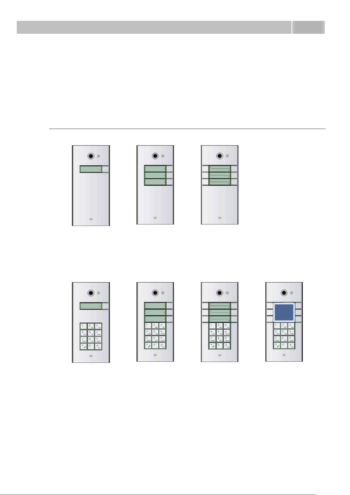
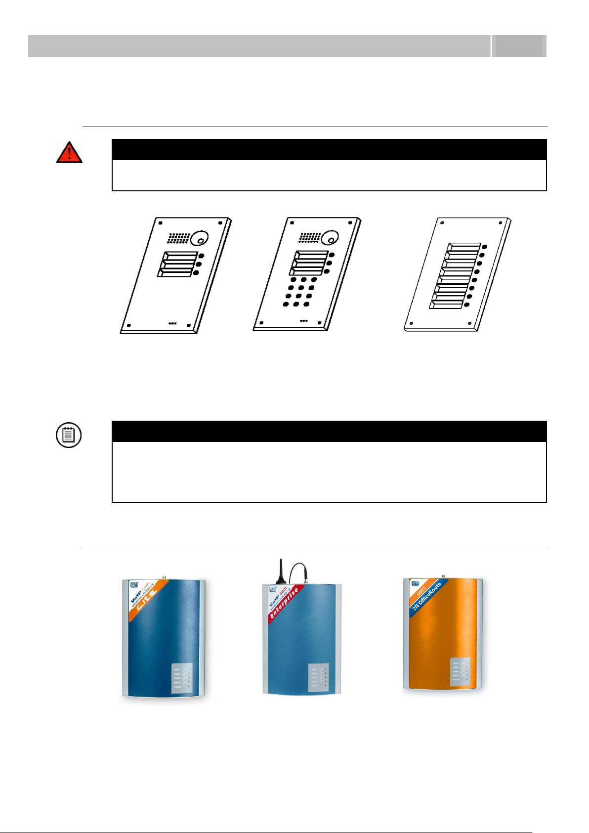
9137110(C)E
9137111(C)E
Basic unit
1 button
9137130(C)E
9137131(C)E
Basic unit
3 buttons
9137160(C)E
9137161(C)E
Basic unit
3×2 buttons
9137110(C)KE
9137111(C)KE
Basic unit
1 button
+ keypad
9137130(C)KE
9137131(C)KE
Basic unit
3 buttons
+ keypad
9137160(C)KE
9137161(C)KE
Basic unit
3×2 buttons
+ keypad
9137160(C)KDE
Basic unit
3×2 buttons
+ keypad
+ display
1.2 2N® Helios IP Components
and Associated Products
Basic Units
(C) = integrated camera
10
Page 11
2N® Helios IP Components and Associated Products
1.2
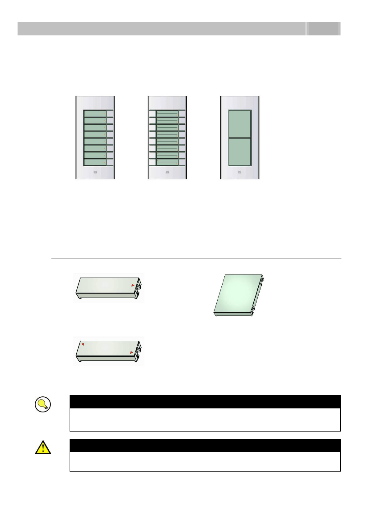
9135181E
Extending module
8 buttons
9135182E
Extending module
8×2 buttons
9135310E
Info panel
Backlit panel without buttons; used
for insertion of a telephone directory,
company logo, house number, etc.
9135311E
Info panel – name plate
Replacing cover for four name tags.
Helps you use a half of the extending
module for insertion of a telephone
directory, working hours, etc.
9135301E
Spare button name plate
9135302E
Spare double-button name plate
Extending modules
Extenders
Tips
All units can be surface mounted without needing any additional accessories.
To make them even more robust and resistant, use a Vandal Resistant mask.
Caution
For flush or outdoor mounting you need to use the accessories; see the
Mounting Accessories subsection.
11
Page 12

2N® Helios IP Components and Associated Products
1.2
91371x1(CK)
2N® Helios IP
Basic
91371x0(CK)
2N® Helios IP
Professional
Number of users
Maximum number of users – phone
directory capacity.
54
999
Number of time profiles
Maximum number of time profiles.
3
20
Electric lock codes
Maximum number of global codes and
user codes for electric lock activation.
2 global,
No user codes
10 global,
User codes available
Telephone mode
Enables 2N Helios IP to behave as an
ordinary telephone – enables the phone
number to be dialled from the keypad.
YES
YES
RTSP server
Built-in RTSP server for audio and video
streaming independently of phone calls.
NO
YES
SIP video
Supports video calls.
YES
YES
Activation codes
Supports codes for activation and
deactivation of users and time profiles.
NO
YES
Substitute function
Enables to enter a substitute for a user
that will be dialled in case the user is
unreachable or inactive.
NO
YES
TFTP client
Automatic configuration and firmware
upgrade from TFTP server.
NO
YES
Extended lock control
Extended settings for built-in and
additional switches.
NO
YES
User sounds
Enables recording of user sounds to
replace standard status signalling
sounds.
NO
YES
Software Facilities of 2N® Helios IP Basic Units
12
Page 13
2N® Helios IP Components and Associated Products
1.2
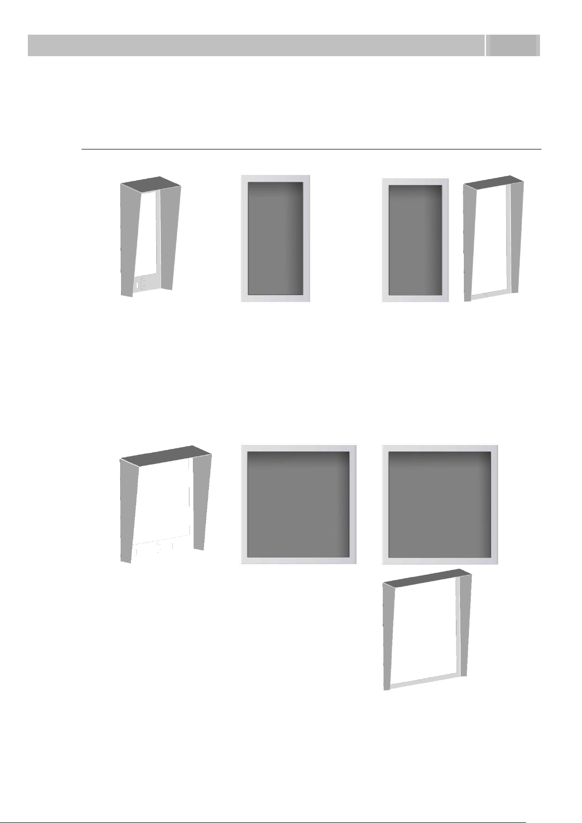
9135331E
Surface 1-module roof
Dimensions
103×218×60 mm
(W×H×D)
9135351E
Wall mounting box
with 1-module frame
Dimensions
125×235×46 mm
(W×H×D)
Wall hole
110×220×50 ±5 mm
9135361E
Wall mounting box
with 1-module roof
Roof dimensions
129×240×41 mm
(W×H×D)
Wall hole
110×220×50 ±5 mm
To upgrade 2N® Helios IP Basic to 2N® Helios IP Professional, use the licence key, Part
No. 9137901.
Mounting Accessories
13
Page 14

2N® Helios IP Components and Associated Products
1.2
9135332E
Surface 2-module roof
Dimensions
203×218×60 mm
(W×H×D)
9135352E
Wall mounting box
with 2-module frame
Dimensions
225×235×46 mm
(W×H×D)
Wall hole
210×220×50 ±5mm
9135362E
Wall mounting box
with 2-module roof
Roof dimensions
229×240×41 mm
(W×H×D)
Wall hole
210×220×50 ±5mm
The mounting accessories are made of stainless steel. For outdoor applications, the
use of the roof is required unless weather protection is provided otherwise. The box
with frame (without roof) allows for installation of 2N® Helios IP in indoor applications
so that the unit does not practically stick out (up to 1 mm).
14
Page 15
2N® Helios IP Components and Associated Products
1.2
9135511E
Vandal resistant mask
basic module + AntiVandal wall mounting
box
9135511KE
1-basic module Vandal
resistant mask with keypad
+ Anti-Vandal wall
mounting box
9135515E
1-extending module Vandal
resistant mask + AntiVandal wall mounting box
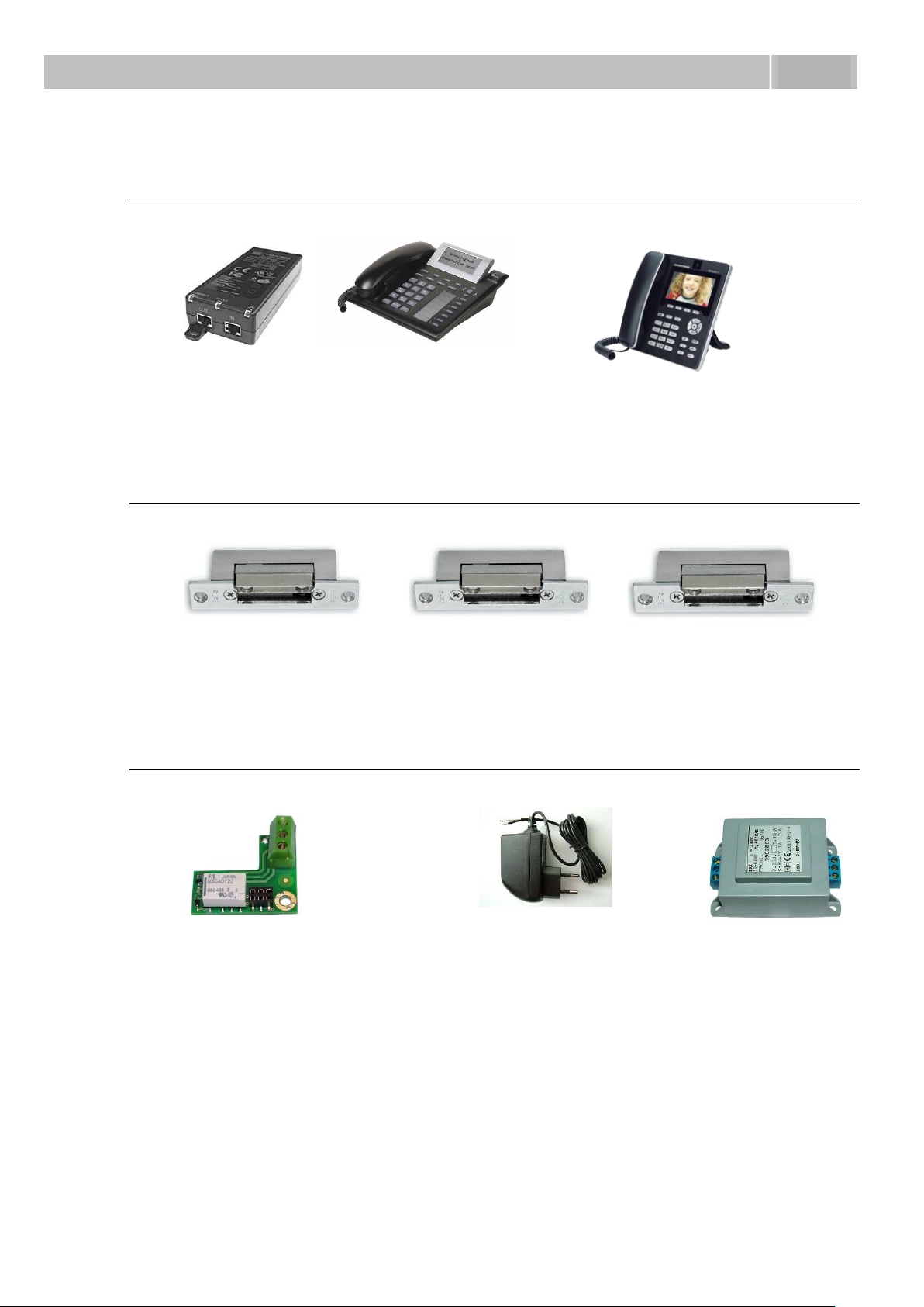
505004E
2N® VoiceBlue Lite
505214E
2N® VoiceBlue Enterprise
505612E
2N® UMTS Office Route
Increased Resistance Accessories
Warning
Item No. 9135351E cannot be used! Use a dedicated box for installation
of the Vandal resistant mask!
Notes
Use these covers to make the basic units or sets with up to 11 buttons
more resistant. Larger assemblies can be provided upon request.
Be sure to use the more resistant version for flush mounting. No roof is
required for outdoor applications of this version.
GSM and UMTS Connection Accessories
15
Page 16
2N® Helios IP Components and Associated Products
1.2
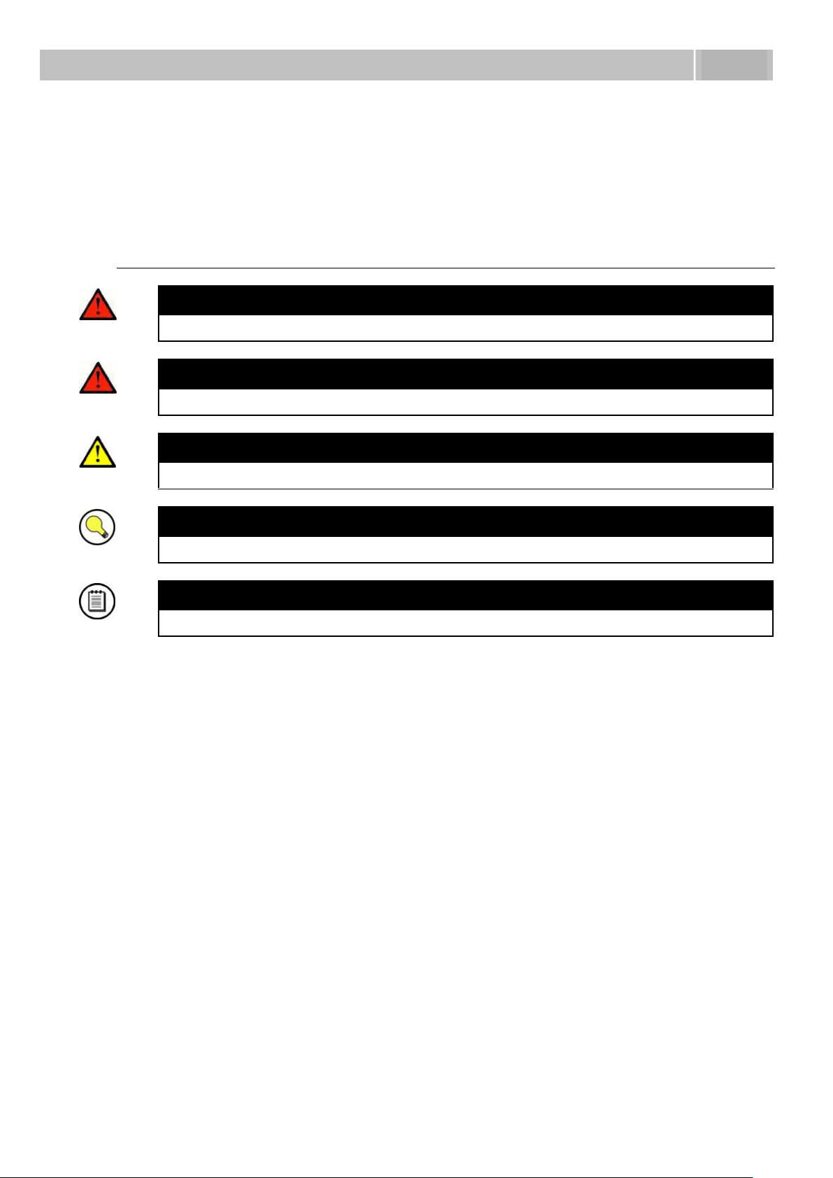
91378100
PoE injector
91378300
Grandstream VoIP telephone
91378350
Grandstream VoIP video telephone
932070E
BEFO 1211 12V / 600 mA
932080E
BEFO 1221
with momentum pin
932090E
BEFO 1211MB
with mechanical blocking
9137310E
Additional switch
Additional appliance control,
normally open/closed contact
option, time-unlimited connection,
up to 48 V/2 A.
91341481E
91341481AU
91341481GB
91341481US
Adapter 12 V/2 A
A stabilised power supply
has to be used if the
Ethernet (PoE) power
supply is not available.
932928E
12 V transformer
VoIP Connection Accessories
Electric Locks
Other Accessories
16
Page 17
Terms and Symbols Used
1.3
1.3 Terms and Symbols Used
Manual Symbols
Safety
Always abide by this information to prevent injury of persons.
Warning
Always abide by this information to prevent damage to the device.
Caution
Important information for system functionality.
Tip
Useful advice.
Note
Additional information.
17
Page 18

Page 19

2
2. Description
and
Installation
This section describes the 2N® Helios IP product and its installation.
Here is what you can find in this section:
Product Description
Before You Start
Mounting – Mechanical Installation
Mounting – Electrical Installation
Connection of Extender Units
19
Page 20

Before You Start
2.1
2.1 Before You Start
Product Completeness Check
Please check whether the contents of the package of your new 2N® Helios IP complies
with the following list.
1 2N
1 installation CD
1 spare seal
1 drilling template
1 hexagonal wrench
1 spare name plate
1 terminal block plug
®
Helios IP
2 screws
2 dowels
20
Page 21
Mounting – Mechanical Installation
2.2
Overview of installation
types
What you need for installation
Indoor, on surface
2N® Helios IP only
Indoor, flush mounting
2N® Helios IP
box with 1-module frame 9135351E
or
box with 2-module frame 9135352E
Outdoor, on surface
2N® Helios IP
Surface 1-module roof 9135331E
or
Surface 2-module roof 9135332E
Outdoor, flush mounting
2N® Helios IP
Wall mounting box with 1-module roof 9135361E
or
Wall mounting box with 2-module roof 9135362E
With increased resistance
2N® Helios IP
Vandal resistant mask with box, version according to
the assembly
2.2 Mounting – Mechanical Installation
Overview of Installation Types
An overview of the installation types and the list of the required components are
provided in the table below.
21
Page 22
Mounting – Mechanical Installation
2.2
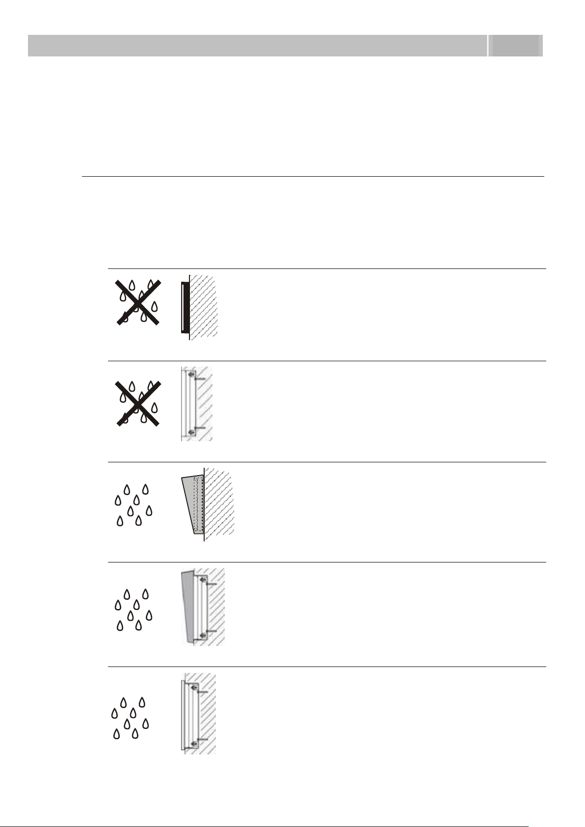
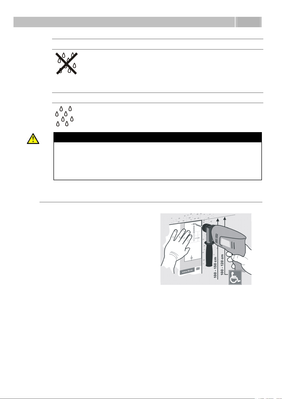
Indoor application means:
Indoor areas with a low relative air humidity value (e.g., hallways,
offices and other heated rooms).
Indoor areas where humidity condenses on walls but never flows
down the walls (porches, storage areas, industrial areas, e.g.).
Outdoor areas where protection against rain and water flowing
down the wall is provided (sheds, passages. e.g.).
Outdoor application means:
Environments where the product is exposed to rain or where water
may flow down the walls (fence, outer wall of a building, e.g.).
Figure 2.1 Hole Drilling
Caution
The warranty shall not apply to product failures and defects caused by
improper installation (contrary to these instructions). The manufacturer is
neither liable for damages caused by theft within an area that is accessible
after the attached electric lock is switched. The product is not designed as
a burglar protection device except when used in combination with a
standard lock, which has the security function.
Surface Mounting
1. Drill holes according to the template included in the 2N
Insert the included dowels in the wall holes.
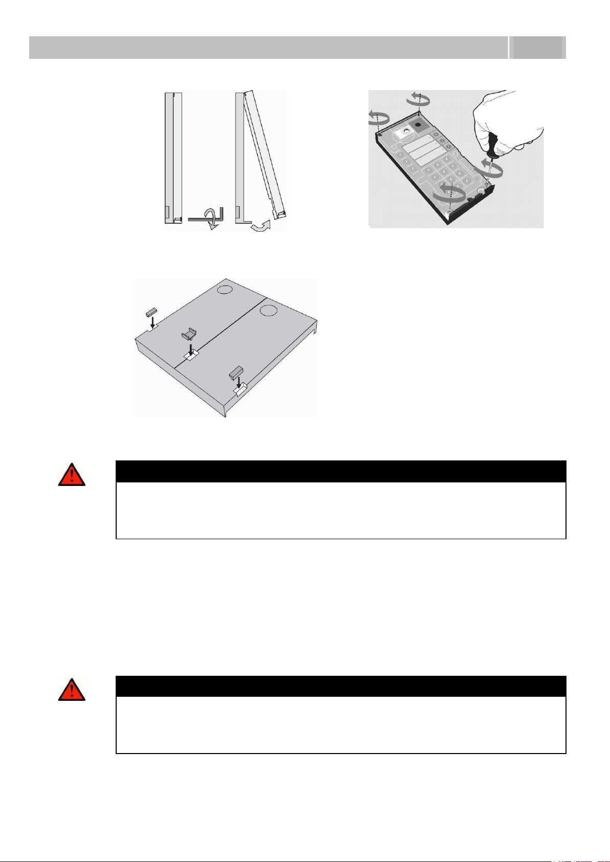
2. Use the hexagonal wrench included in the supply and remove the 2N
IP metal cover. Remove the screw in the lower part of the metal cover and
fold out the cover as shown in Figure 2.2.
3. Use a cross-head screwdriver to remove the plastic cover and demount the
cover.
®
Helios IP supply.
®
Helios
22
Page 23
Mounting – Mechanical Installation
2.2
Figure 2.2 Cover Removing
Figure 2.3 Plastic Cover Removing
Figure 2.4 Multiple-Module Assembly
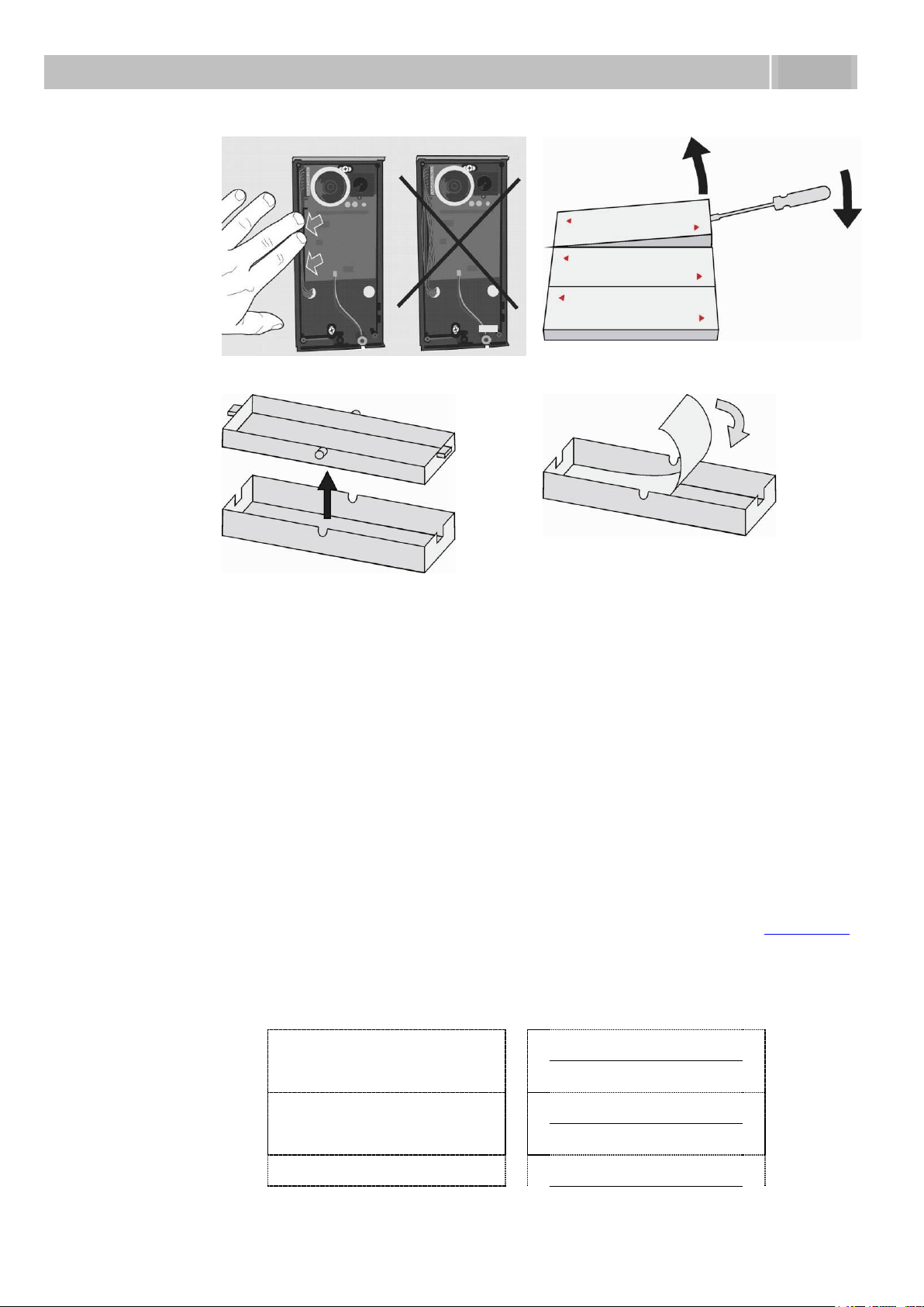
Warning
Never remove the main board or camera electronics from under the lower
cover while installing 2N® Helios IP. Do not disconnect the camera flat
cable from the main board. Do not bend and press upon the flat cable
either.
4. In multiple-module assemblies connect the boxes according to
Figure 2.4, placing the basic module to the left and the extending modules to
the right. The interconnecting cable shall be connected later!
5. Install blank modules on the unused side holes as shown in Figure 2.4.
6. If you are installing a roof module, put it on the wall now.
7. Fix 2N
supply cables (Ethernet, lock, power cables) to the basic module box through
one of the holes.
®
Helios IP on the wall with screws as shown in Figure 2.6. Carry the
Warning
Make sure that the mounting surface for the 2N
communicator is perfectly flat. Avoid mechanical overload upon the
bottom part of the cover. An incorrect installation on an uneven surface
may lead to cover deformation and thus product malfunctions.
®
Helios IP door
23
Page 24

Mounting – Mechanical Installation
2.2
Figure 2.5 Roof Mounting
Figure 2.6 Wall Mounting
8. While installing a roof module, paste its top and side edges to the wall using
silicon glue as shown in Figure 2.5 to prevent water from flowing into the box
along or around the cables.
9. Connect the cables as described in subsection 2.4, Mounting – Electrical
Installation. Make sure that the cables are not squeezed while installing the
plastic cover. For the correct cable installation, refer to Figure 2.7.
10. Remove the protective foil from the display (for display-equipped 2N
IP versions only).
11. Make sure that the cables are placed properly inside and that none of them
obstructs a perfect cover closure.
12. Make sure that the three loudspeaker holder feet fit into the board holes.
Keep the required loudspeaker position to make the seal work properly.
13. Having mounted the unit on the wall and connected all cables, replace the
plastic cover using cross-recessed screws.
®
Helios
Warning
Remember to tighten all the four corner screws to fix the loudspeaker seal
after electric installation to avoid water in-leak! A PH2 cross-head
screwdriver is recommended.
14. Take out the name plates from the plastic cover as shown in Figure 2.8. Use a
flat-bladed screwdriver, for example.
15. Remove the inserts from the name plates.
16. Insert the printed foil labels.
17. Put the inserts back in the name plates.
18. Replace the name plates, clicking them into position. The name plates hold
the matt foil inserted underneath.
19. Check whether a silicon seal is inserted in the top groove of the plastic cover.
A spare seal package is included.
20. Close the metal cover and fix it with screws.
24
Page 25
Mounting – Mechanical Installation
2.2
Figure 2.7 Cabling
Figure 2.8 Name Plate Removing
Figure 2.9 Insert Removing
Figure 2.10 Label Inserting
Single button
(whole)
Double button
(horizontally divided)
Name 01
Name 01
Name 04
Name 02
Name 02
Name 05
Name 03
Name 03
Outdoor installation rules
Always connect button backlighting – it is used for heating.
The joint between the roof module and the wall must be filled with a
waterproof cement to prevent water in-leak (see Figure 2.5).
Water must not leak in along or around the cables.
Name tag material and printing
Each 2N® Helios IP package includes a sheet of transparent foil for laser printing. Cut
the printed foil into pieces and insert the labels in the name plates. Do not use paper
to avoid water in-leak and paper damage.
Red arrows are printed on the name plate. Make sure that the text and the arrow do
not overlap. We recommend you to use a template (MS Word) available at www.2n.cz
for printing.
25
Page 26

Mounting – Mechanical Installation
2.2
Name 06
Flush Mounting
Follow the installation instructions included in the flush mounting box delivery.
Increased Resistance Version Installation
Follow the installation instructions included in the Anti-Vandal box delivery.
26
Page 27

Mounting – Electrical Installation
2.3
2.3 Mounting – Electrical Installation
2N® Helios IP is designed for connection in the Ethernet computer network
(10/100BASE-T) using a UTP cable. Use a CAT 5e UTP cable at least for connection.
2N® Helios IP is fed through the PoE (Power over Ethernet) technology. No additional
cabling is therefore necessary. If your Ethernet is not equipped with the PoE
technology, it is possible to use a PoE injector, Part No. 91378100. As an alternative,
you can use a power adapter, Part No. 91341481E. 2N® Helios IP is configured over
an integrated administration web server, which can be controlled from any web
browser, e.g., Mozilla Firefox.
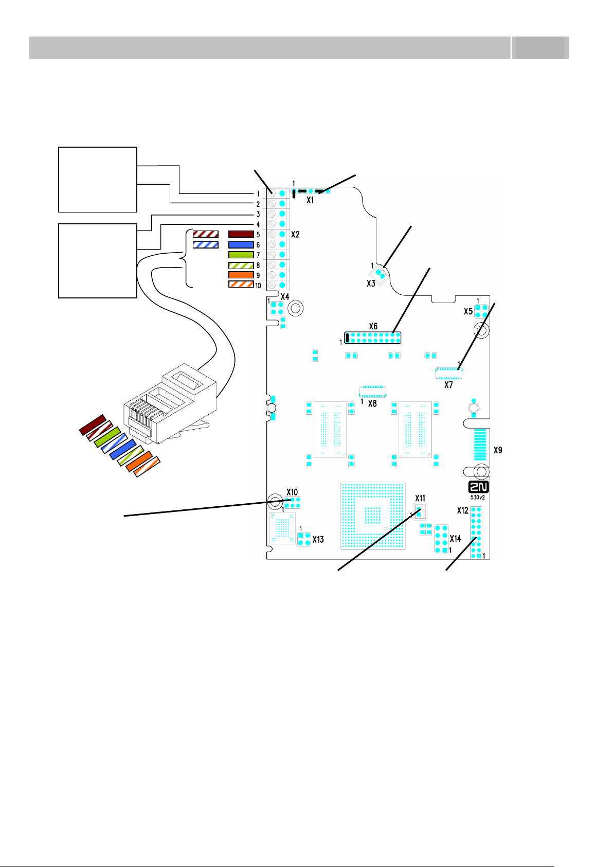
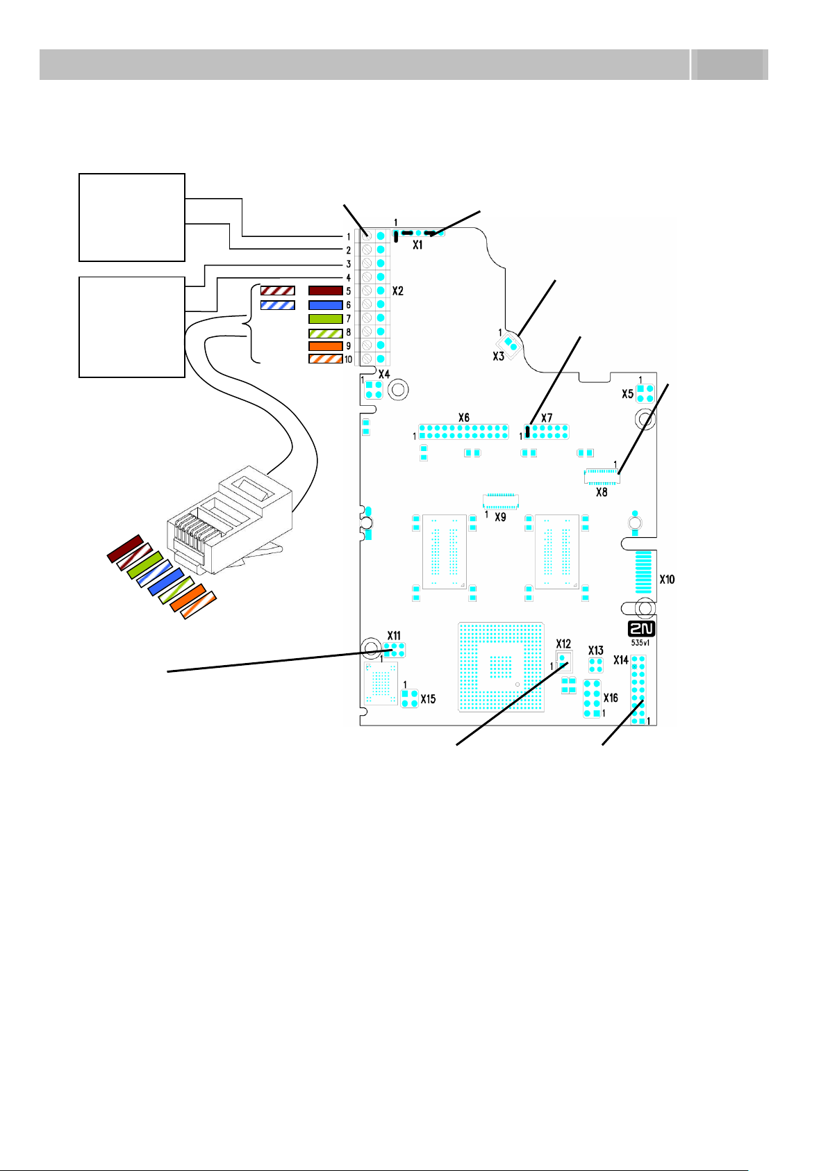
Description of Printed Circuit Board Connectors
In Figure 2.11 you can see the location of the printed circuit board (PCB) connectors.
Connectors to which the accessories can be connected and connectors that serve for
configuring 2N® Helios IP are indicated on the board. The UTP cable for the Ethernet
connection is to be connected to the terminal block X2 as shown in Table 2.1. The
terminal block can be removed from the PCB. The connection of each of the
connectors is described in the subsections below.
27
Page 28
Mounting – Electrical Installation
2.3
+
El. lock
932070E
932080E
932090E
+
Power
adapter
91341481E
Terminal block
–
12V / 2A DC
Configuration connector
Speaker
connector
Microphone
connector
Additional lock
connector
Connector for
extending modules
Camera
connector
Display
connector
+ + –
Figure 2.11 Description of 2N® Helios IP connectors, PCB version 530v2
28
Page 29
Mounting – Electrical Installation
2.3
+
El. lock
932070E
932080E
932090E
+
Power
adapter
91341481E
Terminal block
–
12V / 2A DC
Configuration connector
Speaker
connector
Microphone
connector
Additional lock
connector
Connector for
extending modules
Camera
connector
Display
connector
+ + –
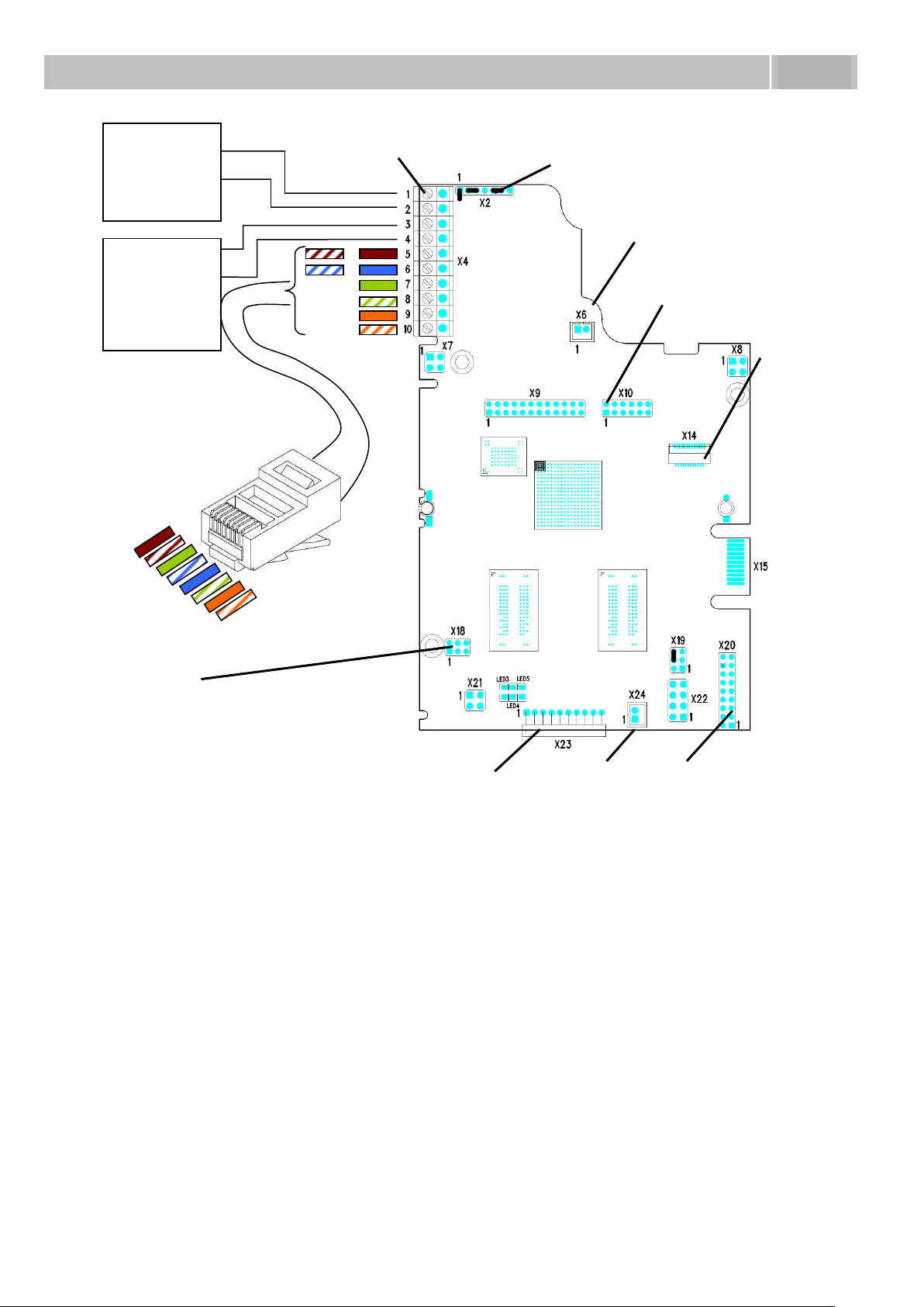
Figure 2.12 Description of 2N® Helios IP connectors, PCB version 535v1, 535v2
29
Page 30
Mounting – Electrical Installation
2.3
+
El. lock
932070E
932080E
932090E
+
Power
adapter
91341481E
Terminal block
–
12V / 2A DC
Configuration connector
Speaker
connector
Microphone
connector
Additional lock
connector
Connector for
extending modules
Camera
connector
Display
connector
+
+
RFID Card reader
connector
Figure 2.13 Description of 2N® Helios IP connectors, PCB version 535v5
Terminal Block X2 Connection
Terminal block X2 includes 10 terminals whose functions are distinguished by colour.
Terminals 5–10 are used for connecting 2N® Helios IP to the Ethernet. Terminals 3–4
are designed for connecting the electric lock and terminals 1–2 help connect an
external 12V / 2A DC power supply if no PoE power supply is available.
1. The terminal block is included in the package. To adjust an already installed
2N® Helios IP, disconnect it IP from the power supply. Then pull to remove
the terminal block from the printed circuit board.
2. Insert the wires under the respective terminals.
3. Tighten the terminals using a flat screwdriver.
4. Replace the terminal block to the printed circuit board.
30
Page 31

Mounting – Electrical Installation
2.3
RJ-45
2N® Helios IP
Pin No.
Marking
Colour
Terminal No.
1
Tx+ 10
2
Tx – 9
3
Rx+ 8
4
PoE – 6
5
PoE – 6
6
Rx – 7
7
PoE + 5
8
PoE + 5
Electric lock
2N® Helios IP
Marking
Colour
Terminal No
932070E
932080E
932090E
– 3
+ 4
5
6
7
8
9
10
1
8
3
4
Caution
Make sure that the cables leading through the 2N
groove are installed properly. For the correct installation of the cables
refer to Figure 2.7.
®
Helios IP cover bottom
Ethernet Connection
For the connections and meanings of the wires see the table below. Join UTP cable
wires 4 (blue) and 5 (white-blue) and attach them under terminal 7 on 2N® Helios IP.
In the same way, join wires 7 and 8 and place them under terminal 5 of 2N® Helios IP.
Table 2.1 Terminal Block Connections
Electric Lock Connection
The electric lock can be connected to terminals 3 and 4 of terminal block X2.
Table 2.2 Terminal Block Connection for Electric Lock
Terminals 3 and 4 are connected to a relay on the 2N® Helios IP board. The relay
terminals may act as normally open or normally closed contacts. Configuration is
performed through the configuration connector X1 as described in the
31
Page 32

Mounting – Electrical Installation
2.3
Electric lock
2N® Helios IP
Marking
Marking
Terminal No.
91341481E
– 1
+ 2
1
2
Configuration Connector Connection subsection. Set on the configuration connector
whether the electric lock will be powered from an external or internal power supply.
External Power Supply Connection
If the Ethernet network is not equipped with the PoE technology, you have two
alternative options how to supply power to 2N® Helios IP.
1. Using a PoE injector, Part No. 91378100. 2N
through an Ethernet cable as shown in Tab. 1 above.
2. Using a power adapter, Part No. 91341481E.
The external power supply from a power adapter can be connected to terminals 1 and
2.
®
Helios IP is then powered
Table 2.3 Terminal Block Connection for Power Adapter
32
Page 33

Mounting – Electrical Installation
2.3
Lock power supply
Relay
Configuration connector
Internal
External
Normally
open
Normally
closed
Connection of jumpers
1 2 3 4 5 6 7
1 2 3 4 5 6 7
1 2 3 4 5 6 7
1 2 3 4 5 6 7
Configuration Connector Connection
The configuration connector is located in the upper part of the printed circuit board.
Use the configuration jumpers to set whether the lock control relay should have a
normally open or normally closed function and whether it should powered internally or
externally.
Table 2.4 Connection of Configuration Connector Jumpers
Display Connector
The display connector includes the name plate backlighting ON/OFF switching pins and
2N® Helios IP resetting pins. The remaining pins are intended for display connection.
33
Page 34

Mounting – Electrical Installation
2.3
Normal
operation
Default
settings
Display
connector X6
PCB version
530v2
Display connector
X7
PCB version
535v1, 535v2
Connector X19
PCB version
535v5
2N® Helios IP resetting procedure
1. Switch 2N
2. Connect the jumper into the resetting (default setting) position (put the
display switch into the F_RES position in the display-equipped models with
535v1 and 535v2 board versions).
3. Switch 2N
4. Switch 2N
5. Remove the jumper from the resetting (default setting) position (put the
display switch into the NORMAL position in the display-equipped models with
535v1 and 535v2 board versions).
6. Switch 2N
®
Helios IP off.
®
Helios IP on and wait for the acoustic start signalling.
®
Helios IP off.
®
Helios IP on.
Table 2.5 Configuration Jumpers on Display Connector
To reset the default values of a display-equipped 2N® Helios IP, put the switch in the
display right-hand bottom corner in position F_RES. This applies to modules with
board versions 535v1 and 535v2 only. For 535v5 versions, use a jumper at connector
X19.
Figure 2.14 Resetting Procedure – Display Model
34
Page 35

Mounting - Completion
2.4
Poorly tightened screw
(a squeezed wire has the same
effect)
WRONG
Gap between plastic cover and
loudspeaker seal
- water may leak in and
damage electronics
2.4 Mounting - Completion
1. Remember to seal the 2N
in-leak and damage to electronics due to condensation.
2. Make sure that the wires inside 2N
plastic top cover (a transparent plastic mould) carefully making its contacts plug
into the electronics board connectors. Push the plastic cover into position
moderately. If the part swings over an obstacle or one corner is higher than the
others, remove the cover and find the obstacle. Then tighten the corner screws
properly.
3. Mounting the metal sheet cover follow the steps included in the subsection
dedicated to name plate removal. Make sure that the cover fits well and is
perfectly flat. If its bottom part is loose, the mounting wall is probably uneven.
Support the corners to avoid 2N® Helios IP bending.
®
Helios IP cable passage hole properly to avoid moisture
®
Helios IP are not squeezed and insert the
Caution
An improper mounting may significantly deteriorate the button function.
A poor outdoor mounting may cause water in-leak and damage to the
electronics.
Most Frequent Mounting Errors
For illustration, a part of the plastic cover is removed in the figures below to reveal the
sealed loudspeaker and the cover–seal touch point. The cross section plane is marked
white for better orientation.
35
Page 36

Mounting - Completion
2.4
WRONG
Gap between plastic cover and
loudspeaker seal
- water may leak in and
damage electronics
If the loudspeaker support is in a
wrong position, the plastic cover
may catch the support brim (see
the arrow) and, if treated roughly,
lead to component deformations.
Leakage may arise, see the upper
arrow.
Properly tightened screw
RIGHT
The seal touches the plastic
cover. Water flows out through a
small hole (not shown in the
figure).
Note: Water does not affect the
loudspeaker Mylar membrane.
36
Page 37

Extending Module Connection
2.5
9135181E (1×8 buttons)
6 5 4 3 2 1 0
9135182E (2×8 buttons)
0 0 1 1 2 2 3
This connector is designed for an
additional extending module.
2.5 Extending Module Connection
2N® Helios IP features an easy installation of extending button modules. Extending
modules are connected using a single cable (included in every extender delivery) in a
chain pattern (every additional unit is connected with the previous one). Each
extending module has two connectors – an input connector (for connection towards
the 2N® Helios IP basic unit) and an output connector (for connection of another,
more remote unit). Be sure to maintain the correct orientation of the units and avoid
connector mismatch to ensure a proper function of the device!
Figure 2.15 Connection of One-Row-Button Extending Modules
Maximum Count of Extenders
Table 2.6 Optional 2N® Helios IP Extension
The table above shows how to combine modules with single (whole) and double
buttons.
37
Page 38

Extending Module Connection
2.5
This connector is designed for
interconnection.
Module Cable Interconnection
The cable is included in every extending module delivery. Both its ends are
the same. Configuration is 1:1. Connectors cannot be shifted or inserted
conversely because they are equipped with a so-called key.
The basic unit is always on the left. Extenders are chain-connected, i.e. each
is linked with its neighbour.
The cable cannot be driven through the box interconnecting holes until the
boxes have been connected (see subsection 2.3 Mounting – Mechanical
Installation).
Figure 2.16 Connection of Two-Button-Row Extending Module
Caution
The extending modules must be connected mutually and with the basic
unit by means of a formed piece supplied with the extending module!!!
38
Page 39

Extending Module Connection
2.5
It is possible to continue to 54
7
15
23
8
16
24
1
9
17
25
10
18
26
11
19
27
Also
applies to
keypad
sets
12
20
28
13
21
29
14
22
30
It is possible to continue to 54
7
15
23
1
8
16
24
2
9
17
25
3
10
18
26
11
19
27
Also
applies to
keypad
sets
12
20
28
13
21
29
14
22
30
Button Numbering
Button numbering – one-button 2N® Helios IP with a
whole-button set
Button numbering – whole-button sets
39
Page 40

Extending Module Connection
2.5
7 15
23 31
39 47
1 4 8
16
24 32
40 48
2 5 9
17
25 33
41 49
3 6
10 18
26 34
42 50
11 19
27 35
43 51
Also
applies to
keypad
sets
12 20
28 36
44 52
13 21
29 37
45 53
14 22
30 38
46 54
Button numbering – double-button set
Caution
For the time being, AntiVandal panels are available only for single-button
sets with one extending module at most.
Button Numbering – Info Panel Sets
Installing the info panel name plate, Part No. 9135311E, into any of the extending
modules will not change the numbering system (the buttons on the info panel sides
will remain functional). Connecting the info panel module, Part No. 9135310E, will
result in omission of eight numbers.
40
Page 41

3
3. 2N
®
Helios IP
Configuration
This section describes the 2N® Helios IP configuration.
Here is what you can find in the section:
Acoustic Signalling and Keypad Configuration
Quick Configuration for Calling
Configuration
41
Page 42

Acoustic Signalling and Keypad Configuration
3.1
Tones
Meaning
User activated
after entering the user activation code. The activation code is
used for activating a user (a telephone directory position). For
activation code setting refer to the Telephone Directory
subsection
User deactivated
after entering the user deactivation code. The deactivation code is
used for deactivating a user (a telephone directory position). A
deactivated user may not be called but the call may, if necessary,
be forwarded to a substitute if defined. For deactivation code
setting refer to the Telephone Directory subsection.
Scheduler activated
used for scheduler activation. It can be used, for example, to
enable alerting of a user group of users in an office. For activation
code setting refer to the Scheduler subsection.
Scheduler deactivated
used for scheduler deactivation. It can be used, for example, to
disable alerting a user group in an office and forward the call to a
selected telephone number, or the reception or a cellular phone.
For deactivation code setting refer to the Scheduler subsection.
Call prolongation confirmation signalling
a maximum call duration is set for blocking protection reasons,
see the Miscellaneous subsection.
Internal application launched
after turning on or restarting of 2N® Helios IP, the internal
application of 2N® Helios IP is launched. A successful launch is
signalled by this tone combination.
Connected to LAN, IP address received
after the launch of the internal application 2N® Helios IP logs into
the LAN. A successful login is signalled by this tone combination.
3.1 Acoustic Signalling and Keypad
Configuration
2N® Helios IP generates sounds to signal operational mode switching and changes.
There are different types of acoustic signals for each type of status change. The list of
signals is included in Table 3.1.
Tone Signalling
42
Page 43

Acoustic Signalling and Keypad Configuration
3.1
Disconnected from LAN, IP address lost
whenever the UTP cable is disconnected from 2N® Helios IP, this
status is signalled by this tone combination.
Invalid telephone number or invalid unlocking code
you can dial an extension telephone number or enter the dooropening code using the keypad. An invalid code is signalled by
this tone sequence.
Switching to default network parameters
after power up, a 30-second timeout is set for entering the
resetting code. For switching to default network parameters refer
to the Switching to Default Network Parameters – Static IP
Address and Switching to Default Network Parameters – Dynamic
IP Address subsections.
Call end signalling
a time limit can be set after which your call will be terminated. To
prolong a call, push a VoIP telephone key. The time limit is set
due to protection against call blocking.
Connected call for VoIP phone-to-2N® Helios IP calling
a short tone is played to signal call connection.
Table 3.1 List of Tone Signals
Switching to Default Network Parameters – Static IP
Address
Switching to the default network parameters with the static IP address can be
performed in two ways. Either through a web interface as described in the Network
subsection or by pushing a combination of the quick dialling buttons as shown in
Figures 3.1–3.3. Upon resetting, the web server is automatically switched on if
switched-off before. The buttons have to be entered within 30 seconds after the
internal application launch as signalled by the tone sequence. The maximum
delay between the buttons is 2 s.
Figure 3.1 Switching to Default Network Parameters – Static IP Address (Part Nos. 9137130E,
9137130CE, 9137130CKE, 9137131E, 9137131CE, 9137131CKE)
43
Page 44

Acoustic Signalling and Keypad Configuration
3.1
Figure 3.2 Switching to Default Network Parameters – Static IP Address (Part Nos. 9137160E,
9137160CE, 9137160CKE, 9137161E, 9137161CE, 9137161CKE)
Figure 3.3 Switching to Default Network Parameters – Static IP Address (Part Nos. 9137110E,
9137110CE, 9137110CKE, 9137111E, 9137111CE, 9137111CKE)
For one-button 2N® Helios IP modules (Part Nos. 9137110E, 9137110CE,
9137110CKE, 9137111E, 9137111CE, 9137111CKE), pushing key 1 fifteen times
within 30 seconds after the internal application launch results in turning on of the
web server and switching the network parameters from the DHCP to the default static
IP address and vice versa.
44
Page 45

Acoustic Signalling and Keypad Configuration
3.1
Switching to Default Network Parameters – Dynamic
IP Address
Switching to the default network parameters with the dynamic IP address can be
performed in two ways. Either through a web interface as described in the Network
subsection or by pushing a combination of the quick dialling buttons as shown in
Figures 3.4–3.6. Upon resetting, the web server is automatically switched on if
switched-off before. The buttons have to be entered within 30 seconds after the
internal application launch as signalled by the tone sequence. The maximum delay
between the buttons is 2 s.
Figure 3.4 Switching to Default Network Parameters – DHCP (Part Nos. 9137130E, 9137130CE,
9137130CKE, 9137131E, 9137131CE, 9137131CKE)
Figure 3.5 Switching to Default Network Parameters – DHCP (Part Nos. 9137160E, 9137160CE,
9137160CKE, 9137161E, 9137161CE, 9137161CKE)
45
Page 46

Acoustic Signalling and Keypad Configuration
3.1
Figure 3.6 Switching to Default Network Parameters – DHCP (Part Nos. 9137110E, 9137110CE,
9137110CKE, 9137111E, 9137111CE, 9137111CKE)
For one-button 2N® Helios IP modules (Part Nos. 9137110E, 9137110CE,
9137110CKE, 9137111E, 9137111CE, 9137111CKE), pushing key 1 fifteen times
within 30 seconds after the internal application launch as signalled by the tone
sequence results in turning on of the web server and switching the network
parameters from the default static IP address to the dynamic address and vice versa.
Web Server Switch On
If the web server is switched off, switch it on using the quick dialling buttons of the
2N® Helios IP basic module as described in Figures 3.7–3.9. The buttons have to be
entered within 30 seconds after the internal application launch as signalled by the
tone sequence. The maximum delay between the buttons is 2 s.
Figure 3.7 Switching on Web Server Using Quick Dialling Buttons (Part Nos. 9137130E, 9137130CE,
9137130CKE, 9137131E, 9137131CE, 9137131CKE)
46
Page 47

Acoustic Signalling and Keypad Configuration
3.1
Figure 3.8 Switching on Web Server Using Quick Dialling Buttons (Part Nos. 9137160E, 9137160CE,
9137160CKE, 9137161E, 9137161CE, 9137161CKE)
Figure 3.9 Switching Web Server Using Quick Dialling Buttons (Part Nos. 9137110E, 9137110CE,
9137110CKE, 9137111E, 9137111CE, 9137111CKE)
For one-button 2N® Helios IP modules (Part Nos. 9137110E, 9137110CE,
9137110CKE, 9137111E, 9137111CE, 9137111CKE), pushing key 1 fifteen times
within 30 seconds after the internal application launch as signalled by the tone
sequence results in turning on of the web server and switching the network
parameters from the default static IP address to the dynamic address and vice versa.
47
Page 48

Quick Configuration for Calling
3.2
3.2 Quick Configuration for Calling
This section describes the most common and convenient way of configuration. For
details on the configuration parameters refer to the subsections below.
Language Selection
Before starting to configure, select the administration web server language using the
folder menu in the right-hand upper corner of the screen.
Network Settings
If you have not set the IP address obtaining from the DHCP server, change the default
IP address of your 2N® Helios IP. To set the IP address, use the Other settings –>
Network menu as shown in the Network subsection.
Static Parameter Setting
For Windows OS users: to know your network parameters, enter in the command line:
ipconfig –all.
Static IP address
Set the IP address assigned by your LAN administrator.
Network mask
Set the network mask.
Default gateway
Set the default network gateway.
Primary DNS
Set the primary Domain Name Server IP address for your LAN.
Secondary DNS
Set the secondary Domain Name Server IP address for your LAN.
48
Page 49

Quick Configuration for Calling
3.2
SIP Parameter Setting
Set your VoIP network parameters to make calls from your 2N® Helios IP. To do this,
use the Other settings –> SIP setting menu.
Display name
Set the name to be displayed to the called subscriber. The name will also be
displayed in the right-hand upper corner of the web interface and used for
2N® Helios IP identification in the 2N® Helios IP Network Scanner application.
User ID
Set the user name to be used for registration.
Domain
Set the domain name or IP address of the server to be used for calling.
Use authorisation ID
Define whether the authorisation ID or user ID shall be used for authorisation.
Authorisation ID
Set the authorisation ID to be used for authorisation if the Use authorisation ID is
set to Yes.
Password
Define the authorisation password for registration and calling.
Local SP port
Set the port to be used by 2N® Helios IP for SIP signalling.
Proxy address
Set the SIP proxy address to be used by 2N® Helios IP for calling.
Proxy port
Set the SIP proxy communication port for SIP signalling.
2N® Helios IP registration
Define whether 2N® Helios IP should register at the SIP proxy.
Registration restricted to:
Set the time for 2N® Helios IP registration.
Registrar address:
Set the registrar address.
Registrar port:
Set the registrar communication port.
49
Page 50

Quick Configuration for Calling
3.2
Telephone Directory Setting
The telephone directory menu is used for configuring the quick dialling buttons (Basic
settings –> Telephone directory). The telephone directory contains 999 positions (only
54 positions are supported in the 9137131(CK), 9137161(CK) and 9137111(CK)
models, 999 positions are supported after the licence key is inserted, Part No.
9137901). The first 54 positions correspond to the quick dialling buttons of 2N® Helios
IP and the buttons of the extending modules attached (see the Mounting - Completion
4. Remember to seal the 2N
in-leak and damage to electronics due to condensation.
5. Make sure that the wires inside 2N
plastic top cover (a transparent plastic mould) carefully making its contacts plug
into the electronics board connectors. Push the plastic cover into position
moderately. If the part swings over an obstacle or one corner is higher than the
others, remove the cover and find the obstacle. Then tighten the corner screws
properly.
6. Mounting the metal sheet cover follow the steps included in the subsection
dedicated to name plate removal. Make sure that the cover fits well and is
perfectly flat. If its bottom part is loose, the mounting wall is probably uneven.
Support the corners to avoid 2N® Helios IP bending.
®
Helios IP cable passage hole properly to avoid moisture
®
Helios IP are not squeezed and insert the
Caution
An improper mounting may significantly deteriorate the button function.
A poor outdoor mounting may cause water in-leak and damage to the
electronics.
Most Frequent Mounting Errors
For illustration, a part of the plastic cover is removed in the figures below to reveal the
sealed loudspeaker and the cover–seal touch point. The cross section plane is marked
white for better orientation.
50
Page 51

Quick Configuration for Calling
3.2
Poorly tightened screw
(a squeezed wire has the same
effect)
WRONG
Gap between plastic cover and
loudspeaker seal
- water may leak in and
damage electronics
WRONG
Gap between plastic cover and
loudspeaker seal
- water may leak in and
damage electronics
If the loudspeaker support is in a
wrong position, the plastic cover
may catch the support brim (see
the arrow) and, if treated roughly,
lead to component deformations.
Leakage may arise, see the upper
arrow.
51
Page 52

Quick Configuration for Calling
3.2
Properly tightened screw
RIGHT
The seal touches the plastic
cover. Water flows out through a
small hole (not shown in the
figure).
Note: Water does not affect the
loudspeaker Mylar membrane.
Extending Module Connection subsection). To retrieve the remaining positions, use the
numeric keypad if available. To select a telephone directory position, use the upper
navigation bar with button numbers. For numbering of 2N® Helios IP buttons,
including extending module buttons, refer to the Button Numbering subsection. To
move between the positions, either use the arrow keys or enter the position number
and push the Move to button (see Figure 3.10).
Figure 3.10 Telephone Directory Navigation Bar
52
Page 53

Quick Configuration for Calling
3.2
Position enable
The Position enable switch defines whether the particular position is enabled or
disabled. You have to enable a position to dial its telephone number. To select a
position status, either push a quick dialling button (for positions 1–54) or enter
the position number using the 2N® Helios IP numeric keypad.
Position name
Here enter a personal name for the selected telephone directory position. This
parameter is optional and facilitates the telephone directory search.
Telephone numbers
Enter up to three telephone numbers for a selected telephone directory position.
These numbers are called sequentially, one after another.
Number 1, 2 and 3:
Enter the station telephone number to which the call should be forwarded. If the
station number included in Number 1 fails to answer, the call will be forwarded
automatically to Number 2, and so on. For the call forwarding timeout refer to the
Miscellaneous subsection.
It is unnecessary to define the remaining parameters for a quick configuration. For
details on the parameters necessary for a detailed configuration, refer to the
subsections below.
53
Page 54

Quick Configuration for Calling
3.2
Lock Setting
To set the lock 1 codes use the Basic settings –> Lock 1 menu.
Lock setting
Set whether and for how long the lock should be active after the correct unlocking
code has been entered.
Lock codes
Enter the lock 1 opening codes for 2N® Helios IP. If a code matches another code
entered earlier in 2N® Helios IP, press . The symbol will appear next to the
code.
Having completed the configuration, restart 2N® Helios IP, refer to the appropriate
subsection. From now on, 2N® Helios IP is ready to make calls.
54
Page 55

Configuration
3.3
3.3 Configuration
2N® Helios IP is configured through an integrated administration web server. Connect
2N® Helios IP to the IP network and make sure that 2N® Helios IP is powered.
IP Address Obtaining from DHCP
By default, obtaining the IP address from the DHCP server is selected in 2N®Helios IP.
After power up, 2N® Helios IP automatically receives the IP address from the DHCP
server. If you do not have access to the DHCP server, you can find the IP address
received with the HeliosIPNetScanner program, which is available on the installation
CD. If 2N® Helios IP is switched to the static IP address mode, switch it to the DHCP IP
address obtaining mode as follows:
1. Power on 2N
2. Wait until 2N
by a sequence of tones .
®
Helios IP.
®
Helios IP completes the booting process. The end is signalled
3. Within 30 seconds push the buttons as described in the Switching to Default
Network Parameters – Dynamic IP Address subsection.
4. Switching to the DHCP IP address obtaining mode is signalled by a sequence
of tones .
5. Wait until the device is restarted.
Manual IP Address Setting
If the DHCP server is unavailable, you can set a default static IP address in your
2N® Helios IP. Proceed as follows:
1. Power on 2N
2. Wait until 2N
by a sequence of tones
3. Within 30 seconds push the buttons as described in the Switching to Default
Network Parameters – Static IP Address subsection.
4. Switching to the default static IP address mode is signalled by a sequence of
tones
®
Helios IP.
®
Helios IP completes the booting process. The end is signalled
.
.
5. Wait until the device is restarted.
6. Now, 2N
®
Helios IP has the following network parameters:
IP address: 192.168.1.100
Network mask: 255.255.255.0
Default gateway: 192.168.1.1
55
Page 56

Configuration
3.3
Description of 2N® Helios IP Network Scanner
The purpose of this application is to find the dynamic IP address of 2N® Helios IP in
the local IP network. The application is available on the installation CD, which is part
of the 2N® Helios IP package. Microsoft NET Framework 2.0 is required for installation.
1. Run the 2N
2. The installation wizard will guide you through the installation.
®
Helios IP Toolkit installer.
Figure 3.11 2N® Helios IP Network Scanner Installation Wizard
3. After installing the 2N
application using the Start menu of the Microsoft Windows operating system.
4. Upon launch, the application starts searching the LAN automatically for all
2N® Helios IP communicators with an assigned or statically set IP address.
The communicators are then listed in a table.
Figure 3.12 2N® Helios IP Network Scanner Window
5. Select the 2N
right-hand mouse button and select Browse... to open the web browser
window, log in to 2N® Helios IP and start configuring as described in the Login
subsection below.
®
Helios IP communicator to be configured. Click on it with the
®
Helios IP Network Scanner application, run the
56
Page 57

Configuration
3.3
Login
In the web browser enter the IP address of 2N® Helios IP. Subsequently, a login
screen will be displayed. The default login username and password are as follows:
Username: Admin
Password: 2n
If the login screen does not appear, an incorrect IP address was entered into the web
browser or the 2N® Helios IP administration web server was turned off. If you are not
sure of the IP address of 2N® Helios IP, use the 2N® Helios IP Network Scanner
application as described in the Description of 2N® Helios IP Network Scanner
subsection.
Find how to switch on the administration web server in the Web Server Switch-On
subsection. Please check the IP address entered, or, if applicable, check the way the
IP address was obtained as described at the beginning of subsection 3.1., Acoustic
Signalling and Keypad Configuration.
Language Selection
You can select the language using the tag menu in the right-hand upper corner as
shown in Figure 3.13.
Figure 3.13 Language Selection
57
Page 58

Configuration
3.3
Information
In this subsection find the basic information on the respective 2N® Helios IP system.
Figure 3.14 Basic Information
Software version – the current 2N® Helios IP firmware version. For firmware
update refer to the
Auto Update subsection.
Bootloader version – the bootloader version.
Hardware version – the 2N® Helios IP hardware version.
Serial number – the product serial number.
MAC address – the Ethernet interface address.
Uptime – the period of time since the last restart.
Registration status – the current 2N® Helios IP-to-SIP proxy registration status:
- In progress – registration in progress.
- Registered – 2N
®
Helios IP is registered to the SIP proxy.
58
Page 59

Configuration
3.3
- Not registered – 2N
proxy.
Registration at – the IP address or domain name of SIP proxy to which 2N® Helios IP
is registered.
Registration time – registration date and time.
Call state – the current call status:
- Inactive – system inactive;
- Call set-up – call being set up;
- Ringing – ringing at VoIP phone;
- Incoming – VoIP phone-to-2N
- Outgoing – 2N
Opponent – displays the SIP address called from 2N® Helios IP.
Call duration – the current call duration.
Audio codec – the audio codec used for the current call.
Video codec – the video codec used for the current call.
DHCP status – displays whether the obtaining of the IP address from the DHCP
server is on.
®
Helios IP is not registered to the SIP
®
®
Helios IP-to-VoIP phone call being set-up.
Helios IP call being set-up;
IP address – the current IP address of 2N® Helios IP.
Net mask – the current subnet mask.
Default gateway – the current default network gateway.
Primary DNS – the current primary Domain Name Server.
Secondary DNS – the current secondary Domain Name Server.
Ethernet frames transmitted – the count of Ethernet frames transmitted.
Ethernet frames received – the count of Ethernet frames received.
Ethernet frames dropped – the count of Ethernet frames dropped due to damage.
UDP packet transmitted – the count of UDP packets transmitted.
UDP packet received – the count of UDP packets received.
UDP packet dropped – the count of UDP packets dropped due to damage.
TCP packet transmitted – the count of TCP packets transmitted.
TCP packet received – the count of TCP packets received.
TCP packet dropped – the count of TCP packets dropped due to damage.
59
Page 60

Configuration
3.3
Telephone Directory
To set the telephone directory, use the Basic settings –> Telephone directory tag. The
telephone directory includes 999 records – positions. Typically, one position
corresponds to one user. You can assign up to three phone numbers to each
position/user.
Figure 3.15 Telephone Directory
To move between the positions either use the arrow buttons, or enter the position
number and push the Move to button in the right-hand upper corner.
The first 54 positions are the same as the quick dialling buttons on 2N® Helios IP and
buttons on the extending modules (refer to the Button Numbering subsection). For the
other positions use the numeric keypad if available in your 2N® Helios IP.
60
Page 61

Configuration
3.3
General Settings
Position enabled
Here select whether the selected telephone directory position shall be enabled or
disabled. Remember to enable a position to call to its number.
Position name
Enter the name of the person to be assigned to a selected telephone directory
position. This parameter is optional and helps you search the telephone directory
more easily.
Telephone Numbers
Here define up to three telephone numbers to be called one after another when a
quick dialling button or keypad is used.
Numbers 1,2 and 3
Enter the telephone number to which the call is to be routed. If the call is not
answered by the station with the telephone number specified under Number 1, it
will be forwarded automatically to the telephone number specified under Number
2 and so on.
2N® Helios IP also allows for direct calling in the format sip:user_id@domain:port,
e.g.: sip:200@192.168.22.15:5062 or sip:name@yourcompany.
Time schedule
Assign a time schedule to a telephone number for validity management. Refer to
the Scheduler subsection for details on time schedule settings.
Substitute if inaccessible
Enter the person to whom the call will be routed if the original person is not
reached (for Part Nos. 9137131(CK)E, 9137161(CK)E, 9137111(CK)E with a
proper licence key only, Part No. 9137901).
User Activation and Deactivation
Here set the user activation and deactivation codes. The user may activate or
deactivate 2N® Helios IP using the user telephone or numeric keypad. If just one code
is set, or both the codes are the same, the current user status will be switched after
code entering. You can verify the selected status by a sound signalling. Together with
the scheduler settings, the user activation and deactivation define whether a call will
be established for the given telephone number (for Part Nos. 9137131(CK)E,
9137161(CK)E and 9137111(CK)E with a licence key only, Part No. 9137901).
User Door Lock Codes
Write the user codes for 2N® Helios IP unlocking. Each user may be assigned two
unique codes for lock 1 and 2 opening. If the codes are identical with other codes
already entered in 2N® Helios IP, the following mark will appear with the respective
codes: (for Part Nos. 9137131(CK)E, 9137161(CK)E and 9137111(CK)E a licence
key is required, Part No. 9137901).
61
Page 62

Configuration
3.3
Scheduler
The scheduler helps you set conditioned calling to user numbers. In case a user is not
present, 2N® Helios IP need not set up a call to his or her telephone number but can
automatically call other telephone numbers in the directory or the substitute number.
Each user number can be assigned a scheduler – profile. A total of 20 profiles can be
shared by the users (for Part Nos. 9137131(CK)E, 9137161(CK)E, 9137111(CK) this
number is 3, or 20 with a licence key only, Part No. 9137901). There are two possible
ways of profile validity condition setting: time setting in the Time schedule, or manual
setting of the profile activation and deactivation codes. For you to use both the
functions at the same time, the two conditions must be met at the same time.
Figure 3.16 Scheduler Set-up
General Settings
Profile name
Enter the scheduler profile name. This parameter is optional and helps you search
the list of profiles more easily.
62
Page 63

Configuration
3.3
Profile Time Schedule
Set the presence of a user in a week period. A profile is active if the current time
matches the set parameters. To use this function properly, make sure that the current
time data have been set properly on the device (see the Date and Time subsection).
Profile Activation and Deactivation
Set the manual user activation and deactivation codes. To activate or deactivate a
profile, use the DTMF code from the user telephone or the 2N® Helios IP numeric
keypad. If just one code is set, or both the codes are the same, the current user
status will be switched over after code entering. You can verify the selected status by
a sound signalling. If no code is set, the function is inactive and the profile status
depends on the time schedule.
User Active if…
Set at what user and profile status the telephone directory numbers will be called. The
settings are applicable only if the time schedule is set for the given telephone number
in the directory. See the Telephone Directory subsection (for Part Nos. 9137131(CK)E,
9137161(CK)E and 9137111(CK)E this function is supported with a licence key only,
Part No. 9137901.)
Profile active only (user independent)
A telephone directory number is called only if the profile is active.
Example of use: you want to call the reception desk during working hours.
Profile & user active
A telephone directory number is called only if the profile and the user are active.
Example of use: you want to call the secretary‘s office during working hours and
the secretary‘s presence.
Profile active & user inactive
A telephone directory number is called only if the profile is active and the user is
inactive.
Example of use: you want to call the reception desk during working hours when
the secretary is absent.
Profile or user active
A telephone directory number is called if the profile or the user is active.
Example of use: you want to call the stock release department during working
hours or when the personnel are present.
Profile active or user inactive
A telephone directory number is called if the profile is active or the user is
inactive.
Example of use: you want to call a technician’s cellular phone during lunch time or
the technician’s absence.
63
Page 64

Configuration
3.3
Locks
This menu helps you set the opening codes and modes for locks 1 to 4 attached to
2N® Helios IP (for Part Nos. 9137131(CK)E, 9137161(CK)E and 9137111(CK), locks 3
and 4 are supported only if a licence key is inserted, Part No. 9137901).
Figure 3.17 Lock Settings
Lock Settings
Lock enabled
Enable or disable lock control globally. If disabled, the lock cannot be opened with
any of the codes entered (including the user lock codes) or activated by a call or
speed dialling button.
Time profile
Assign a time schedule to the lock code for global management. If the assigned
time schedule is not active, the lock switch cannot be opened with a lock code or
activated by a call or speed dialling button. Refer to the Scheduler subsection for
details on time schedule settings.
64
Page 65

Configuration
3.3
Lock mode
Select either the mono-stable and bi-stable lock switch mode. The switch is
automatically switched off after a predefined switch-on time in the mono-stable
mode. The first activation opens and the second activation closes the switch in the
bi-stable mode.
Switch-on duration
Set the lock switch-on time in the mono-stable mode. The time interval set here is
not applied to the bi-stable mode.
Sound signalling
Set the sound signalling type during lock switch-on status. Select one of the
following: Short tone, Long tone (during the whole switch-on time), or a User
sound, refer to Subs. User Sounds.
Display info
Enable or disable displaying of lock switch-on signalling.
Output relay
Assign one of the following switching relays to the lock: Basic switch or Additional
switch (Part No. 9137310E).
Synchronise with
Enable lock synchronisation for automatic lock switch activation after a predefined
time interval after another lock switch activation. Use the Synchronisation delay
parameter to set the timeout value.
Synchronisation delay
Set the time interval for synchronised activation of lock switches. The parameter
is not applied if the Synchronise with function (above) is not enabled.
Activate by call
Set lock activation by an incoming/outgoing call. The switch is active during the
whole call in the bi-stable lock switch mode. The switch is activated by the call
start and deactivated after a predefined switch-on time in the mono-stable mode.
Quick dial button
Assign one of the speed (quick) dial buttons to the lock switch. Push this speed
dial button to activate the lock switch. Once assigned to a lock switch, this button
cannot be used for dialling.
External command
Switch-on command
Set the command to be sent to an external device (WEB relay, e.g.) via the HTTP
protocol (GET request) whenever the lock switch is activated. The required format
is http://ip_address/path. Example: http://192.168.1.50/relay1=on.
Switch-off command
Set the command to be sent to an external device (WEB relay, e.g.) via the HTTP
protocol (GET request) whenever the lock switch is deactivated. The required
format is http://ip_address/path. Example: http://192.168.1.50/relay1=off.
65
Page 66

Configuration
3.3
Lock Codes
A list of the universal lock codes to be entered using a telephone set or the 2N® Helios
IP keypad. The count of these global lock codes is 10 (or 3 for Part Nos.
9137131(CK)E, 9137161(CK)E, 9137111(CK)E unless a licence key is used, Part No.
9137901). In addition to these ten codes, each user may be assigned a user-dedicated
unlocking code (for Part Nos. 9137131(CK)E, 9137161(CK)E and 9137111(CK)E with a
licence key only, Part No. 9137901.)
Access
Disable code entering from the user‘s numeric keypad or telephone set.
Time profile
Assign a time schedule to the lock code for validity management. Refer to the
Scheduler subsection for details on time schedule settings.
Lock code options
Enable ON/OFF mode
You are recommended to enable different activation/deactivation codes while
setting the bi-stable lock mode. Use this parameter to set a mode where odd
codes (1, 3, 5, …) are used for lock switch activation and even codes (2, 4, 6, …)
for lock switch deactivation. If this mode is OFF (default setting), then any code
makes the lock switch turn into the opposite state (ON/OFF). This does not apply
to the mono-stable lock switch mode where the activation time is prolonged.
66
Page 67

Configuration
3.3
Network
This menu is used for setting the 2N® Helios IP network parameters. A change of any
of these parameters will not show until the next 2N® Helios IP restart.
By default, obtaining the IP address from the DHCP server is switched on in
2N® Helios IP (DHCP client enabled). To find the IP address of your 2N® Helios IP, use
the 2N® Helios IP Network Scanner program included on the CD. If, in your LAN, the
DHCP server is not used or properly configured for your 2N® Helios IP, you can push
the appropriate quick dialling button sequence to switch 2N® Helios IP into the fixed IP
address mode (see the Switching to Default Network Parameters – Dynamic IP
Address subsection).
DHCP Settings
DHCP client enabled
Switch on the function of obtaining the IP address from the DHCP server.
Static Settings
For Windows OS users: find the network parameters by entering ipconfig –all in the
command line.
Static IP address
Set the static IP address assigned by your local network administrator.
Network mask
Set the network mask.
Default gateway
Set the default network gateway.
Primary DNS
Set the IP address of the primary Domain Name Server used in your LAN.
Secondary DNS
Set the IP address of the secondary Domain Name Server used in your LAN.
NAT Settings
These settings are applicable only if 2N® Helios IP is operated in a LAN and assigned
no public IP address.
67
Page 68

Configuration
3.3
External IP address
Set the public IP address for your router to which 2N® Helios IP is connected. If
2N® Helios IP’s IP address is public, leave this field blank.
Figure 3.18 Network Parameter Setting
Date and Time
This menu helps you set the time zone and time synchronisation using the NTP server.
For manual data and time setting refer to the Tools subsection.
Time Zone
Time zone
Set the time offset at the place of installation relative to the GMT – Greenwich
Mean Time. This setting is intended for switching on/off the daylight saving time
in spring and autumn.
68
Page 69

Configuration
3.3
TZ rule
If 2N® Helios IP is installed in a location not included in the Time zone parameter,
specify the time shift offset and daylight saving time switch on/off manually here.
Remember to set the Time zone to the Use TZ rule below function.
Figure 3.19 Date and Time Settings
Time Synchronisation
Use NTP server
Enable or disable the 2N® Helios IP synchronisation using the NTP (Network Time
Protocol) server.
NTP server address
Set the IP address of the NTP server for 2N® Helios IP time synchronisation.
SIP Settings
In order to set up calls from 2N® Helios IP, define your VoIP network parameters. To
do this use the Advanced settings –> SIP settings menu.
Remember to restart 2N® Helios IP after setting the SIP parameters.
69
Page 70

Configuration
3.3
Figure 3.20 SIP Settings
User Settings
Display name
The name to be displayed to the called party. The name will also be displayed in
the right-hand upper corner of the web interface and used for 2N® Helios IP
identification in the 2N® Helios IP Network Scanner application.
User ID
Set the user ID for registration.
Domain
Enter the domain name or IP address of the server to be used for calling.
Use authorisation ID
Set whether 2N® Helios IP should use the authorisation ID or user ID only for
authorisation.
Auth ID
Enter the authorisation ID to be used for authorisation if the Use authorisation ID
parameter is set to Yes.
70
Page 71

Configuration
3.3
Password
Enter the password to be used for authorisation during registration and calling.
Other Settings
Local SIP port
Set the communication port to be used for SIP signalling by 2N® Helios IP. The
change of this parameter will not show until the next 2N® Helios IP restart. The
default value is 5060.
Send KeepAlive packets
Set whether or not 2N® Helios IP should periodically query about the state of the
called station using the SIP OPTIONS requests during a call. Use this option to
detect a disconnected or defective station.
Initial RTP port
Set the initial port for the range of 60 RTP ports to be used for audio and video
transfers. The default value is 5000 (i.e. the range of 5060-5059).
RTP Timeout
Set the time limit for receiving audio stream RTP packets during a call. When the
limit is exceeded, the call is terminated by 2N® Helios IP. Set 0 to disable this
limitation.
SIP Proxy Settings
Proxy address
Set the IP address of the SIP proxy used by 2N® Helios IP for calling.
Proxy port
Set the SIP signalling port to the SIP proxy.
SIP Proxy Registration
Register 2N® Helios IP
Set whether 2N® Helios IP should register with the SIP proxy.
Registration expires
Set the minimum time for 2N® Helios IP registration attempts.
Registrar address
Set the registrar IP address.
Registrar port
Set the registrar communication port.
71
Page 72

Configuration
3.3
Administration Web Server
This menu helps you configure the administration web server.
Web Server Settings
Web server
You can disable the administration web server launching. The change of this
parameter will not show until the next 2N® Helios IP restart. To enable the web
server, follow the instructions mentioned in the Web Server subsection.
Web server port
Set the web server communication port. The change of this parameter will not
show until the next 2N® Helios IP restart
Web server language
Set the default language after login to the web server.
Figure 3.21 Web Server Configuration
72
Page 73

Configuration
3.3
Access Passwords
Admin password
Set the administrator password for 2N® Helios IP configuration through the
administration web server. Enter the new password into both of the Admin
password and Confirm password fields.
Audio
This menu is used to set the 2N® Helios IP audio parameters.
Figure 3.22 Audio Parameter Settings
Speaker Settings
Master volume
Set the global loudspeaker volume. This parameter controls the volume of the
calls and all acoustic signalling.
Audio volume
Adjust the loudspeaker volume for a call.
73
Page 74

Configuration
3.3
Warning volume
Set the volume of the 2N® Helios IP signal tones that announce status changes.
Key beep volume
Set the volume of the tone generated whenever a key is pushed.
Lock open volume
Set the volume of the unlocking signalling tone.
Call tones
Set the volume of the dialling, ringing and busy tones if generated by 2N® Helios IP.
Ringing
Set the volume of the incoming call signalling tone – ringing tone. Incoming calls
are signalled when the automatic incoming call receiving function is off, see the
Miscellaneous subsection.
Microphone Settings
Sensitivity
Set the microphone sensitivity.
AGC (Automatic Gain Control)
Set whether the Automatic Gain Control function should be used.
Noise reduction
Set the mode for noise reduction arising primarily during echo cancellation.
Video
This menu is used to set the video camera. To set the codec properties use the
Advanced Settings –> Video codecs menu, see the Video Codecs subsection.
Brightness
Set the intensity of the video camera stream.
Colour saturation
Set the colour saturation of the video camera stream.
Flip horizontally
Set whether the picture is to be flipped horizontally.
Frame rate decreasing
Enable an automatic decreasing of the frame rate under poor light conditions,
which improves the video quality to the detriment of the frame rate.
Flicker avoidance
Here you can eliminate flicker caused by artificial sources of light such as fluorescent
lamps. The flicker frequency depends on the light source power supply frequency.
74
Page 75

Configuration
3.3
Figure 3.23 Video Parameter Settings
Audio Codecs
This tag is used for configuration of priorities of the use of audio codecs.
Preferred Audio Codecs
Set the audio codecs for 2N® Helios IP telephone call set-ups. Select G.711 (PCMA or
PCMU), L16, or G.729. Audio codec priorities are determined by the sequence: the
first codec in the sequence has the highest priority. Codec G.729 is available with a
licence key only, Part No. 9137902.
75
Page 76

Configuration
3.3
Transmission Quality Settings
Jitter compensation
Set the buffer length to compensate jitter caused by variable delays between
incoming RTP packets. A longer buffer mans a better transmission quality yet a
higher transmission delay.
QoS DSCP for audio
Set the priority of the audio transmitting packets in the network. The value is
copied into the ToS (Type of Service) field in the IP packet header.
Caution
Wrong settings may deteriorate the transfer quality. Do not change this
parameter if you are not sure. The change in transfer quality will show
only in case the network components support this service.
Figure 3.24 Audio Codec Settings
DTMF receiving and Sending
Defines how DTMF signalling should be received and sent. Check the opponent‘s
parameters for correct settings.
76
Page 77

Configuration
3.3
1. Receive as audio / Send as tones – transmits the DTMF signals in the audio
channel. This setting is unsuitable for cases where the audio channel is
comprised using high-compression codecs such as GSM codecs.
2. Receive as RTP / Send as RTP – transmits DTMF signalling as special RTP
packets according to the RFC2833 recommendation.
3. Receive as SIP INFO / Send as SIP INFO – transmits DTMF signalling using
the SIP INFO packets as recommended in RFC2976.
To send DTMF signalling during a call use the 0 to 9, * and # keys. You can
also disable this function, enable for outgoing calls only, or enable for
incoming and outgoing calls by setting the Send during call parameter.
Video Codecs
2N® Helios IP uses video codec H.264 or H.263. You can set their parameters in such
a manner that the video transmitted conforms to the needs of the opponent.
Figure 3.25 Video Codec Settings
Preferred Video Codecs
Set the priority of video codecs for call set-ups.
77
Page 78

Configuration
3.3
Video Codec Settings
Video resolution
Set the picture formats of the video transmitted. The resolution values range from
QCIF (176x144) to VGA (640×480).
Frame rate
Set the frame rate for frames to be sent by 2N® Helios IP to the VoIP network.
Video bit rate
Set the transmission rate for video transmission from 2N® Helios IP. The lower the
bit rate the greater picture compression is necessary. This results in a lower
picture quality on the receiving end. A high bit rate does not have to mean
significant improvement of transmission as a whole because the network may get
overloaded, resulting in a greater packet loss rate or delay.
Video packet size
Set how large the video transmitting packet should be.
Quality Settings
QoS DSCP for video
Set the priority of the video transmitting packets in the network. The value is
copied into the ToS (Type of Service) field in the IP packet header.
Caution
Wrong settings may deteriorate the transfer quality. Do not change this
parameter if you are not sure. The change in the transfer quality will show
only in case the network components support this service.
Advanced RTP Settings
RTP payload type
Set the Media Format value of the Media attribute (a) in the SPD part of the
INVITE message. Some SIP proxies require this value for a successful video call
set-up. If 0 is selected, the given RTP payload type is not used. It is necessary to
disable one RTP payload type in some SIP proxies, e.g. the Cisco Call Manager.
Caution
Wrong settings may result in a loss of network compatibility. Do not
change this parameter if you are not sure. Losing network compatibility
may cause video transmission errors.
78
Page 79

Configuration
3.3
Polycom phone compatibility
Set compatibility of SDP messages with some Polycom and Cisco phones. With
this mode on, 2N® Helios IP does not include the sendonly flag in the codec
specification for video streams.
Streaming
This function is available to 2N® Helios IP Part Nos. 9137131(CK)E, 9137161(CK)E and
9137111(CK)E with a valid licence key only, Part No. 9137901.
This menu allows the user to enable audio and video streaming into your LAN without
affecting the other functions of 2N® Helios IP. This function may be used for security
purposes. An RTSP supporting receiver is required for acceptance of audio and video
streaming. For this purpose, it is possible to download the VLC Media player software
free of charge. For the VLC media player configuration see below.
RTSP Server
RTP server
Enable and disable audio and video streaming.
Allow IP address
Specify the allowed IP address of the stream-receiving user. If the value is not
entered, you can require the stream from any IP address.
Caution
2N
®
Helios IP enables to send a single stream at a time. When a stream
request comes from another IP address, the current stream is
discontinued and the stream is distributed to the IP address that sent the
request.
79
Page 80

Configuration
3.3
Enable audio stream
Set whether the audio channel is part of the stream transmitted.
Enable video stream
Set whether the video channel is part of the stream transmitted.
Figure 3.26 Video Streaming Setting
Quality Settings
QoS DSCP for video
Set the priority of the video transmitting packages in the network. The value is a
decimal number and defines individual bits in the ToS (Type of Service) field in the
IP packet header (bits 8–16).
Caution
Wrong settings may deteriorate the transfer quality. Do not change this
parameter if you are not sure. The change in transfer quality will show
only in case the network components support this service.
80
Page 81

Configuration
3.3
Video Codec Settings
Video codec
Set one of the following codec modes for video streaming: H.264/MPEG4-AVC or
MPEG4 Part2.
Video resolution
Set the individual picture formats for the video transmitted. The resolution values
range from QCIF (176x144) to VGA (640×480).
Frame rate
Set the frame rate for frames to be transmitted.
Video bit rate
Set the bit rate for video transmission. The parameter affects the compression
ratio and thus the video transmission quality.
Video packet size
Set the size limits for the video transmitting RTP packet.
VLC Set-Up for Streaming Video from 2N® Helios IP
1. Install the VLC Media player application (version 0.9.4 in this manual).
2. After installation and start, the window will be displayed as shown in the
figure below.
Figure 3.27 VLC Media Player Main Window
3. In the main menu select the source for playing the video, Media->Open
Network.
Figure 3.28 Open Network Connection
81
Page 82

Configuration
3.3
4. In the network card select the RTSP protocol and insert the IP address of the
2N® Helios IP device that is sending the video streaming (192.168.3.175 in
this case).
Figure 3.29 RTSP Stream IP Address Setting
5. After the confirmation button OK is pushed, the video player window will
appear.
Figure 3.30 Streaming Video Receiving
6. Push the STOP button to stop receiving the video signal.
7. Open a window of the playlist, Playlist –> Show playlist.
82
Page 83

Configuration
3.3
Figure 3.31 Show Playlist
8. The playlist window will display the list of played records, in this case the
RTSP stream from 2N® Helios IP (IP address 192.168.3.175).
Figure 3.32 Playlist Window
9. Save the playlist using the Playlist –> Save playlist to file... menu.
Figure 3.33 Save Playlist
10. From now on, whenever opened, the playlist will immediately display video
streaming from the selected 2N® Helios IP device.
83
Page 84

Configuration
3.3
Figure 3.34 Streaming Video Receiving
JPEG Video Setting
Anonymous access
You can download a JPEG video from any IP address without authentication.
Otherwise, the video is only accessible after login or during a call if the Call
activation is enabled.
Call activation
Set whether the JPEG video is available to the terminal upon the call beginning.
The function must be supported by the terminal (Snom 820/870, e.g.).
Frame rate
Set the transmission rate to be offered to the end terminal.
JPEG quality
Set the JPEG image quality. The recommended value is 85. The parameter affects
the image size and quality.
JPEG Video Use
The JPEG video can be used for any application that is capable of downloading
JPEG images from 2N® Helios IP web interface.
To load an image from a camera enter any of the links below in your web
browser:
http://helios_ip_address/enu/camera160x120.jpg
http://helios_ip_address/enu/camera320x240.jpg
http://helios_ip_address/enu/camera352x272.jpg
84
Page 85

Configuration
3.3
http://helios_ip_address/enu/camera352x288.jpg
http://helios_ip_address/enu/camera640x480.jpg
Be sure to enable the Anonymous access to the JPEG video (see above) for
this function.
You can assign displaying JPEG images to a Snom 820/870 terminal button.
To do this, set the Action URL function and enter one of the commands below
as the parameter:
Chyba! Odkaz není platný. or
http://helios_ip_address/enu/snom870-video.xml.
Auto Update
2N® Helios IP allows both for manual and automatic updates of configuration and
firmware. The automatic update is done through a TFTP server. For Part Nos.
9137131(CK)E, 9137161(CK)E and 9137111(CK)E this function is supported only if a
licence key is inserted, Part No. 9137901.
Figure 3.35 Firmware Update
85
Page 86

Configuration
3.3
Automatic Update
TFTP server address
The IP address of the TFTP server where the firmware and configuration are
located that are to be automatically uploaded to 2N® Helios IP.
Update firmware
Enable/disable automatic firmware downloading from the TFTP server.
Update time
Set a period for automatic firmware downloading attempts from the TFTP server.
2N® Helios IP periodically (at a predefined time once a day) checks the TFTP
server for a later firmware version. Having found one, 2N® Helios IP updates the
firmware and restarts automatically. With this parameter you can choose the most
convenient time of a day for updating (when 2N® Helios IP is not very busy).
File prefix
Specify the TFTP firmware directory path or file prefix. 2N® Helios IP expects the
firmware file to be named Xiphelios_app.bin, where X is the prefix specified in this
parameter.
Update configuration
Enable or disable automatic configuration downloading from the TFTP server.
Update period
Set the time interval after which 2N® Helios IP gets connected to the TFTP server
for configuration file downloading.
File prefix
Specify the TFTP configuration directory path or file prefix. 2N® Helios IP expects
the configuration file to be named Xiphelios_config.ini, where X is the prefix
specified in this parameter.
Update display data
Enable/disable automatic display data/program updating from the TFTP server.
The display data are updated in the same time intervals together with the
configuration file.
File prefix
Specify the TFTP display data directory path or file prefix. 2N® Helios IP expects
the configuration file to be named Xiphelios_disp.bin, where X is the prefix
specified in this parameter.
Display
The 9137161KDE and 9137161CKDE 2N® Helios IP models are equipped with a colour
TFT display, which shows variable information such as digital name tags, telephone
directories, 2N® Helios IP statuses and/or user-defined images. You can set the basic
display parameters in this menu. For the display data uploading to 2N® Helios IP refer
to the Display Program.
86
Page 87

Configuration
3.3
Figure 3.36 Display
Display Settings
Display enable
Enable or disable the display use.
Maximum idle timeout (ads)
Set the maximum display idle time (i.e. when the user does not control the device
using the buttons or numeric keypad), after which the advertisement or userdefined image displaying mode is switched on automatically.
Maximum idle timeout (name tags)
Set the maximum display idle time (i.e. when the user does not control the device
using the buttons or numeric keypad), after which the structured telephone
directory mode is switched into the name tag displaying mode.
Search mode
Set the mode of searching users in the telephone directory displayed. Either use
the initial name characters (prefixes) or every occurrence of the set characters in
the name (any occurrence).
87
Page 88

Configuration
3.3
System Log
This menu is used for configuration of system and log message sending. This service is
useful for solving 2N® Helios IP errors if any and contacting the 2N TELEKOMUNIKACE
a.s. Technical Support. Normally, it is not necessary to configure this menu. To receive
syslog messages, a syslog server has to be installed in your PC.
Figure 3.37 System Log
Logging enable
Enable or disable sending of system and log reports and storing them on the
syslog server.
Trace level
Set the level of detail of the reports.
Syslog server
The IP address of the server on which the system log application is running.
Miscellaneous
Here set the additional parameters of 2N® Helios IP that were not included in the
above-described menus.
88
Page 89

Configuration
3.3
Figure 3.38 Miscellaneous Settings
Outgoing Calls
Ring time limit
Set the call set-up and ringing time limits for outgoing calls. If the calls are routed
through the GSM gateways of Part Nos. 505004, 505214 or 505612 to the GSM
network, it is advisable to set a time value longer than 20 s.
Call time limit
Set the maximum call duration. When the call end is approaching, 2N® Helios IP
starts generating tones signalling the end of the call. The call will automatically be
terminated 10s after this signal. To prolong the call, send a DTMF code (push #,
e.g.) on your phone.
Dial cycles limit
Set the maximum count of telephone directory searching attempts. The function is
useful whenever the substitute is defined and in the case of deadlock.
89
Page 90

Configuration
3.3
Incoming Calls
Automatic answer
Defines how 2N® Helios IP should behave when a call is coming. If the Automatic
answer is disabled, 2N® Helios IP signals an incoming calls by ringing and the
external subscriber can answer or reject the call by pushing * or # respectively. If
the Automatic answer is enabled, 2N® Helios IP receives the call automatically and
processes as selected in the Activation mode and Activation code parameters.
Activation mode
If the Automatic answer is enabled, incoming calls are received automatically by
2N® Helios IP. 2N® Helios IP enables you to receive up to 3 incoming calls at the
same time. You can control 2N® Helios IP through incoming calls using tone
dialling from your telephone keypad (activate or deactivate users or profiles,
e.g.). A single incoming call may only be connected with the 2N® Helios IP
microphone, loudspeaker and camera. Use the Activation mode parameter to
define whether the incoming call should be connected automatically, or the
activation code should be required for connection (see below).
Activation code
Set the activation code necessary for interconnecting the incoming call audio and
video if the Automatic answer is enabled and the Activation code is set to Manual.
Beep on connect
Use this parameter to enable/disable 2N® Helios IP connection signalling by a beep
during an incoming call.
Keyboard Settings
Hang up by # button
Enable call termination with the # key.
Same button function
Assign a function to the call-establishing quick dialling button when re-pushed.
None – re-pushing the quick dialling button does not affect the set up or
active call.
Hang-up – re-pushing the quick dialling button ends the set-up or active call.
Dial next – re-pushing the quick dialling button allows you to skip an attempt
to set up a call and proceed to the next telephone
number in the directory for another set-up.
Flash – re-pushing the quick dialling button sends the FLASH signal into the
active call.
Quick dialling using digits
Enable user calling from the telephone directory by dialling the user number (two
or three digits) and confirmation with *.
Floor & Apartment dialling
Enable special calling to numbers included in the telephone directory by entering a
floor number on the numerical keypad and pushing a quick dialling button.
Buttons 1 – 6 represent apartments on the floor (A through F). The following
90
Page 91

Configuration
3.3
floors and apartments are assigned to telephone directory positions: 01A – 1, 01B
– 2, 01C – 3, 01D – 4, 01E – 5, 01F – 6, 02A – 7, 02B – 8 etc. until 99F – 594.
Keystroke timeout
Set the delay between two digits when entering a code or telephone number using
the 2N® Helios IP keypad.
Enable telephone mode
Enable to set up calls directly to the telephone numbers entered from the
2N® Helios IP numeric keypad using the *telephone_number* key sequence.
Dial digits limit
Define the maximum number of digits of a telephone number in the Telephone
mode. When the defined count is reached, the telephone number is dialled
automatically without the need to push * subsequently.
Legacy lock code
Set whether the first code in the lock 1 and lock 2 list may be entered from a VoIP
phone valid without an * confirmation.
Other Settings
Backlight level
Set the level of the keypad backlight.
DHCP on/off by buttons
Set whether a quick dialling button combination may switch to obtaining the IP
address from the DHCP server upon the 2N® Helios IP restart as described in the
Switching to Default Network Parameters – Dynamic IP Address subsection.
Enable lock control by HTTP
Enable lock control by HTTP requests sent by 2N® Helios IP. Select ON, OFF or
change over upon the following HTTP (GET) request:
http://helios_ip_address/enu/lockstate.xml.p?lockXstate=Y, where X is the lock
number (1-4) and Y is 0 for switch off, 1 for switch on and 2 for change over.
91
Page 92

Configuration
3.3
Tools
This menu helps you set the 2N® Helios IP date and time manually and reboot the device.
Figure 3.39 Tools
Local Date and Time Setting
Used for date and time setting in case the NTP synchronisation is disabled (see the
Date and Time subsection). Push the button to synchronise the 2N® Helios IP
time with your PC time.
Reboot device
Used for device restarting in case of changes of some configuration parameters,
namely network settings, administration web interface settings and some SIP
configuration parameters.
92
Page 93

Configuration
3.3
Configuration
This menu is used for configuration downloading, uploading and resetting.
Figure 3.40 Configuration Setting
Download configuration from device
Used for downloading configuration from 2N® Helios IP. To save the configuration,
push . Use the checkboxes to select the configuration parts to be downloaded.
Upload configuration to device
Used for uploading configuration to 2N® Helios IP. Use the Browse button to select
the configuration file and push to upload it to 2N® Helios IP. Use the
checkboxes to select the configuration parts to be uploaded. For copying the
configuration file from another 2N® Helios IP device, disable the network and SIP
setting downloading to avoid network collision and use of one and the same SIP
configuration. For automatic configuration update refer to the
Auto Update subsection.
Resetting of all parameters
Resets all 2N® Helios IP parameters to default values.
93
Page 94

Configuration
3.3
Caution
This selection does not apply to the network settings to avoid network
collision and disabling the option to configure using the administration web
server. To reset the network settings to default values use the procedure
described in the Switching to Default Network Parameters – Static IP
Address and Switching to Default Network Parameters – Dynamic IP
Address subsections.
Display Program
This menu is used for display program uploading. The display program is prepared
using the configuration tool available on the attached CD. For display settings refer to
the Display subsection.
Display Program Uploading
Used for uploading the display program to 2N® Helios IP. Use the Browse button
to select the configuration file and push to upload it to 2N® Helios IP. If no
file is selected, the current display program is removed from the memory when
this button is pressed.
Figure 3.41 Display Program Uploading
94
Page 95

Configuration
3.3
Firmware
This menu is used for manual firmware updating.
Manual Firmware Update
Used for manual firmware updating using the configuration web interface. Use
the Browse button to select the new firmware file and push to upload it
to 2N® Helios IP. For automatic update refer to the
Auto Update subsection.
Figure 3.42 Firmware
95
Page 96

Configuration
3.3
User Sounds
This menu helps create customised signalling of 2N® Helios IP states by replacing the
default tone signalling with user sound files.
User Sound Upload
Used for handling user sound files within 2N® Helios IP. Push the Browse button to
select a sound file and then push to upload the file into 2N® Helios IP. The user
sound format is an 8bit or 16bit .WAV file with 8kHz sampling frequency. Push to
remove the file uploaded. Push to play and verify the recorded sound on your PC.
Figure 3.43 User sounds
The following user sounds can be used:
96
Page 97

Configuration
3.3
Hang-up by remote party – here replace the disconnect tone signalling that
the called station has hung up.
Busy tone – replace the standard busy tone.
Invalid input – replace the invalid lock switch password sound.
Invalid position – replace the speed dial button sound signalling a non-
programmed telephone directory position.
Lock switch activation – replace the lock switch activation sound.
Ringing – replace the standard incoming ringing tone when the Automatic
call answering function is off, refer to the Miscellaneous
subsection.
97
Page 98

Configuration
3.3
Network Trace
This menu helps capture incoming and outgoing packets on the 2N® Helios IP network
interface. The file with the captured data can be downloaded and analysed, using,
e.g., Wireshark (www.wireshark.org). Push the Start button to launch capturing and
the Stop button to terminate capturing.
The captured packets are stored in the ring buffer of the size of 4MB. Whenever the
buffer is filled up, the oldest packets are deleted automatically. You are recommended
to reduce the video stream transmission speed for packet capturing below 512kbps.
Figure 3.44 Network trace
Licence
This menu is used for entering licence keys, Part Nos. 9137901 and 9137902. Licence
keys upgrade the 2N® Helios IP functionality (see the Software Facilities of 2N® Helios
IP Basic Units subsection). Contact your local distributor for the licence key to your
2N® Helios IP.
98
Page 99
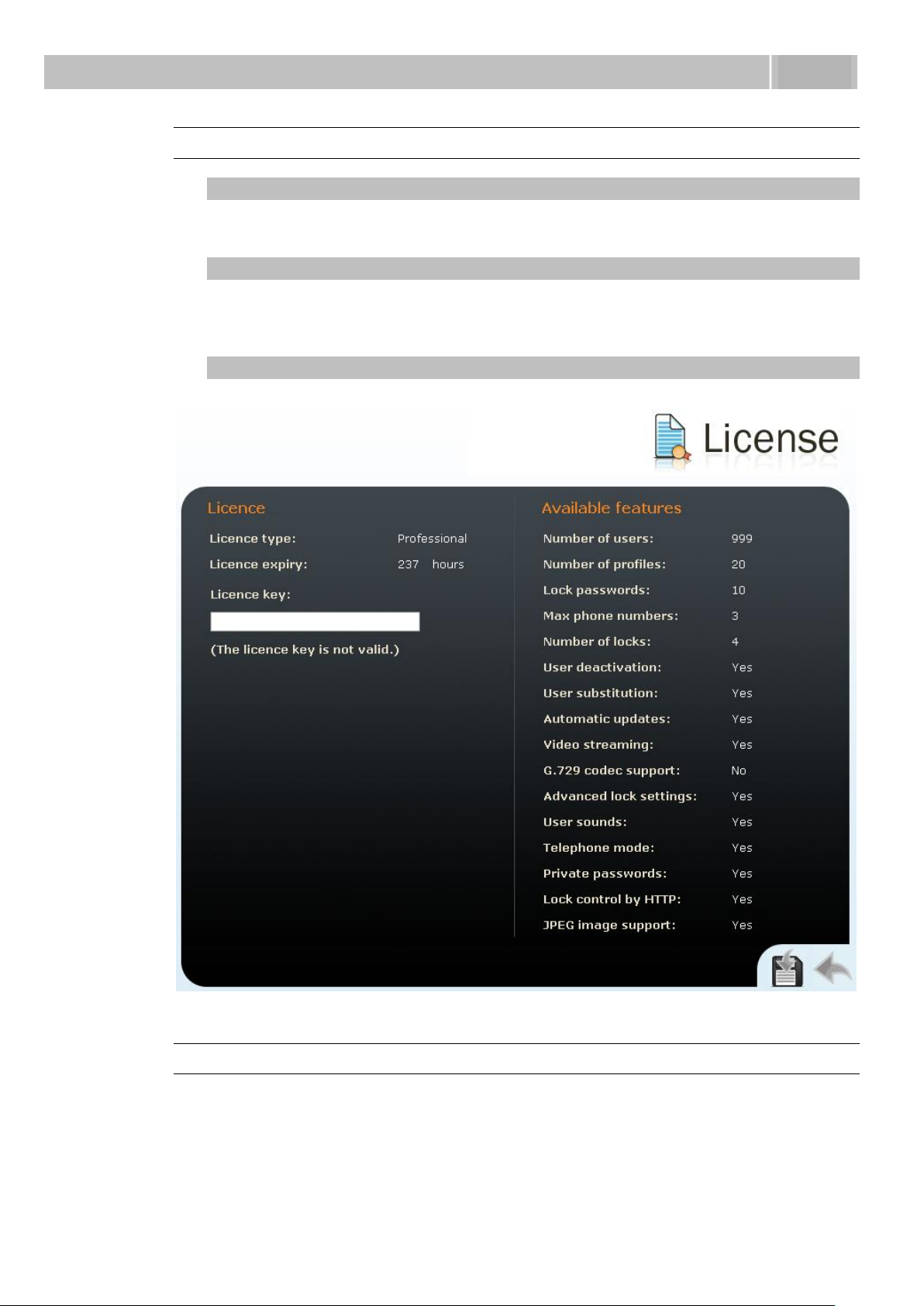
Configuration
3.3
Licence
Licence type
Displays the type of licence currently saved in 2N® Helios IP. The available
features of your licence are displayed in the Available features subsection.
Licence expiry
2N® Helios IP models of Part Nos. 9137131(CK), 9137161(CK) and 9137111(CK)
are distributed with the Professional trial licence limited to 800 hours. Every
restart subtracts 1 hour from this value.
Licence key
Enter the licence key received from your distributor in this field.
Figure 3.45 Licence
Available Features
Provides details on the 2N® Helios IP features following from the applicable licence.
99
Page 100

 Loading...