


Toshiba RAM-SM800BT-E, RAM-SM800UT-E, RAM-SM560KRT-E, RAM-SM560BT-E, RAM-SM560UT-E User Manual
...FILE NO. A02-013
SERVICE MANUAL
<OWNER’S MANUAL/INSTALLATION MANUAL>
SPLIT TYPE
RAV-SM560AT-E/RAV-SM800AT-E RAV-SM560UT-E/RAV-SM800UT-E RAV-SM560BT-E/RAV-SM800BT-E RAV-SM560KRT-E/RAV-SM800KRT-E
R410A
PRINTED IN JAPAN, Apr.,2003 ToMo

ADOPTION OF NEW REFRIGERANT
This Air Conditioner is a new type which adopts a new refrigerant HFC (R410A) instead of the conventional refrigerant R22 in order to prevent destruction of the ozone layer.
WARNING
Cleaning of the air filter and other parts of the air filter involves dangerous work in high places, so be sure to have a service person do it. Do not attempt it yourself. The cleaning diagram for the air filter is there for the service person, and not for the customer.
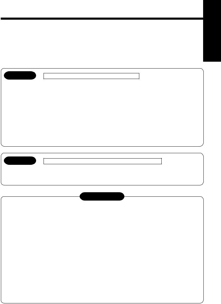
4-Way Air Discharge Cassette Type ————————————
OWNER’S MANUAL |
|
ACCESSORIES ...................................................................... |
15 |
PRECAUTIONS FOR SAFETY .............................................. |
15 |
PARTS NAME ......................................................................... |
17 |
PARTS NAME OF REMOTE CONTROLLER ......................... |
18 |
CORRECT USAGE ................................................................. |
20 |
AUTOMATIC OPERATION (Auto Changeover) .................... |
21 |
ADJUSTMENT OF WIND DIRECTIONd ................................ |
22 |
TIMER OPERATION ............................................................... |
23 |
MAINTENANCE ..................................................................... |
24 |
AIR CONDITIONER OPERATIONS AND PERFORMANCE . 27 |
|
RE-INSTALLATION ................................................................ |
28 |
TROUBLES AND CAUSES .................................................... |
28 |
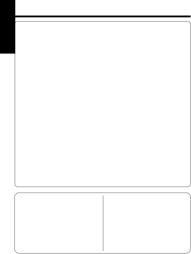
Concealed Duct Type ——————————————————
OWNER’S MANUAL |
|
ACCESSORIES ...................................................................... |
49 |
PRECAUTIONS FOR SAFETY .............................................. |
49 |
PARTS NAME ......................................................................... |
51 |
PARTS NAME OF REMOTE CONTROLLER ......................... |
52 |
CORRECT USAGE ................................................................. |
54 |
AUTOMATIC OPERATION (Auto Changeover) .................... |
55 |
TIMER OPERATION ............................................................... |
56 |
MAINTENANCE ..................................................................... |
57 |
AIR CONDITIONER OPERATIONS AND PERFORMANCE . 59 |
|
RE-INSTALLATION ................................................................ |
60 |
TROUBLES AND CAUSES .................................................... |
60 |
TROUBLES AND CAUSES |
|
(Concerning Remote Controller) ......................................... |
62 |
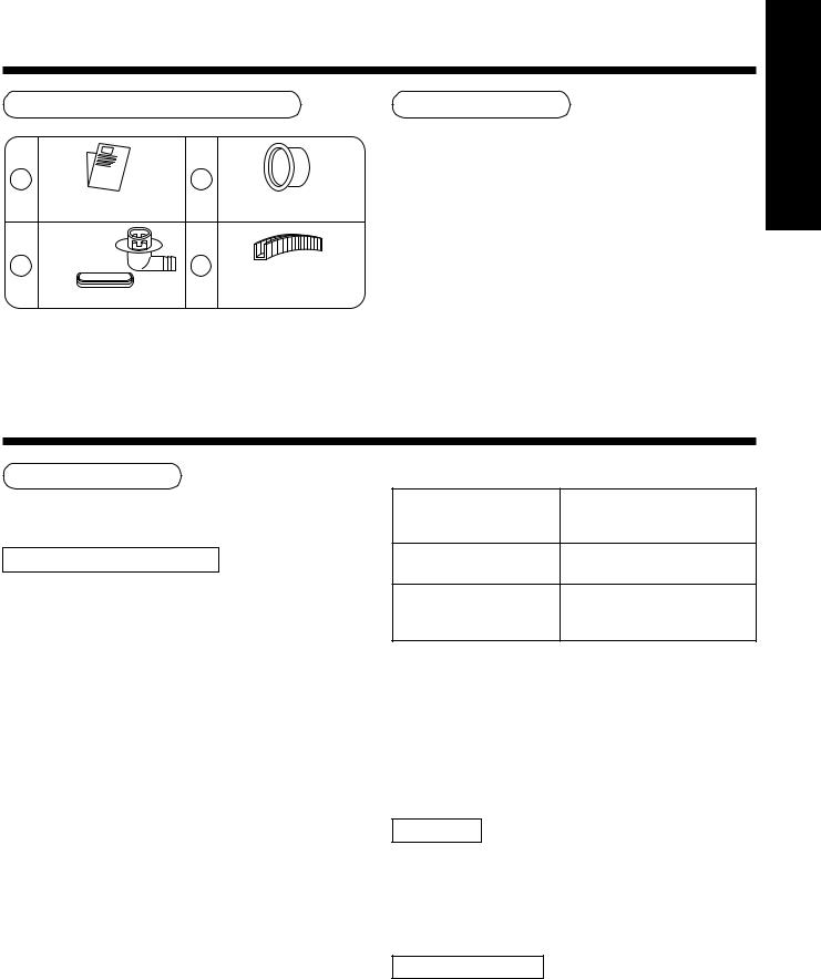
High-Wall Type —————————————————————
OWNER’S MANUAL |
|
ACCESSORIES ...................................................................... |
79 |
PRECAUTIONS FOR SAFETY .............................................. |
79 |
PARTS NAME ......................................................................... |
81 |
NAME AND FUNCTIONS OF |
|
INDICATORS AND CONTROLS ............................................ |
81 |
NAME AND OPERATIONS OF |
|
INDICATORS AND CONTROLS ............................................ |
82 |
CORRECT USAGE ................................................................. |
84 |
DRY OPERATION ................................................................... |
85 |
AUTOMATIC OPERATION (Auto Changeover) .................... |
85 |
ADJUSTING AIR FLOW DIRECTION .................................... |
86 |
HOW THE AIR CONDITIONER WORKS ................................ |
86 |
TEMPORARY OPERATION ................................................... |
87 |
MAINTENANCE ..................................................................... |
87 |
AIR CONDITIONER OPERATIONS AND PERFORMANCE . 89 |
|
PROBLEMS AND CAUSES ................................................... |
90 |
??? ——————————————————————————
OWNER’S MANUAL
Outdoor Unit ––––––––– RAV-SM800AT-E/RAV-SM800AT-E
INSTALLATION MANUAL
PRECAUTIONS FOR SAFETY ................................................ |
1 |
ACCESSORY AND REFRIGERANT ........................................ |
3 |
SELECTION OF INSTALLATION ............................................. |
3 |
REFRIGERANT PIPING ........................................................... |
8 |
EVACUATING ......................................................................... |
10 |
ELECTRICAL WORK ............................................................. |
12 |
FINAL INSTALLATION CHECKS ........................................... |
13 |
RAV-SM800AT-E RAV-SM800AT-E
RAV-SM560UT-E/RAV-SM800UT-E
INSTALLATION MANUAL
Accessory parts and Parts to be procured locally ............ |
31 |
PRECAUTIONS FOR SAFETY .............................................. |
32 |
SELECTION OF INSTALLATION PLACE .............................. |
34 |
DRAIN PIPING WORK ........................................................... |
39 |
REFRIGERANT PIPING ......................................................... |
41 |
EVACUATING ......................................................................... |
42 |
ELECTRICAL WORK ............................................................. |
44 |
TEST RUN .............................................................................. |
47 |
TROUBLESHOOTING ............................................................ |
48 |
RAV-SM560BT-E/RAV-SM800BT-E
INSTALLATION MANUAL |
|
Accessory parts and Parts to be procured locally ............ |
63 |
PRECAUTIONS FOR SAFETY .............................................. |
64 |
SELECTION OF INSTALLATION PLACE .............................. |
66 |
INSTALLATION OF INDOOR UNIT ........................................ |
67 |
AIR DUCTING WORK ............................................................ |
70 |
DRAIN PIPING WORK ........................................................... |
74 |
REFRIGERANT PIPING ......................................................... |
75 |
EVACUATING ......................................................................... |
76 |
ELECTRICAL WORK ............................................................. |
77 |
INSTALLATION/SERVICING TOOLS ..................................... |
78 |
RAV-SM560KRT-E/RAV-SM800KRT-E
INSTALLATION MANUAL
Accessory parts and Parts to be procured locally |
............ 91 |
PRECAUTIONS FOR SAFETY .............................................. |
92 |
INSTALLATION PROCEDURE .............................................. |
94 |
SELECTION OF INSTALLATION PLACE .............................. |
95 |
INSTALLATION OF INDOOR UNIT ........................................ |
95 |
DRAIN PIPING WORK ........................................................... |
96 |
REFRIGERANT PIPING ......................................................... |
98 |
EVACUATING ......................................................................... |
99 |
ELECTRICAL WORK ........................................................... |
102 |
IMPROVING SYSTEM EFFICIENCY ................................... |
104 |
FINAL INSTALLATION CHECKS ......................................... |
104 |
ENVIRONMENT .................................................................... |
106 |
|
|
???
INSTALLATION MANUAL
RAV-SM560UT-E RAV-SM800UT-E
RAV-SM560BT-E RAV-SM800BT-E
RAV-SM560KRT-E RAV-SM800KRT-E
???
1 PRECAUTIONS FOR SAFETY
•Ensure that all Local, National and International regulations are satisfied.
•Read this “PRECAUTIONS FOR SAFETY” carefully before Installation.
•The precautions described below include the important items regarding safety. Observe them without fail.
•After the installation work, perform a trial operation to check for any problem.
Follow the Owner’s Manual to explain how to use and maintain the unit to the customer.
•Turn off the main power supply switch (or breaker) before the unit maintenance.
•Ask the customer to keep the Installation Manual together with the Owner’s Manual.
CAUTION New Refrigerant Air Conditioner Installation
•THIS AIR CONDITIONER ADOPTS THE NEW HFC REFRIGERANT (R410A) WHICH DOES NOT DESTROY OZONE LAYER.
The characteristics of R410A refrigerant are ; easy to absorb water, oxidizing membrane or oil, and its pressure is approx. 1.6 times higher than that of refrigerant R22. Accompanied with the new refrigerant, refrigerating oil has also been changed. Therefore, during installation work, be sure that water, dust, former refrigerant, or refrigerating oil does not enter the refrigerating cycle.
To prevent charging an incorrect refrigerant and refrigerating oil, the sizes of connecting sections of charging port of the main unit and installation tools are charged from those for the conventional refrigerant.
Accordingly the exclusive tools are required for the new refrigerant (R410A).
For connecting pipes, use new and clean piping designed for R410A, and please care so that water or dust does not enter. Moreover, do not use the existing piping because there are problems with pressure-resistance force and impurity in it.
RAV-SM800AT-E RAV-SM800AT-E
CAUTION To Disconnect the Appliance from Main Power Supply.
This appliance must be connected to the main power supply by means of a switch with a contact separation of at least 3 mm.
The installation fuse (25A D type  ) must be used for the power supply line of this conditioner.
 WARNING
•Ask an authorized dealer or qualified installation professional to install/maintain the air conditioner.
Inappropriate installation may result in water leakage, electric shock or fire.
•Turn off the main power supply switch or breaker before attempting any electrical work.
Make sure all power switches are off. Failure to do so may cause electric shock.
•Connect the connecting cable correctly.
If the connecting cable is connected in a wrong way, electric parts may be damaged.
•When moving the air conditioner for the installation into another place, be very careful not to enter any gaseous matter other than the specified refrigerant into the refrigeration cycle.
If air or any other gas is mixed in the refrigerant, the gas pressure in the refrigeration cycle becomes abnormally high and it may resultingly causes pipe burst and injuries on persons.
•Do not modify this unit by removing any of the safety guards or by by-passing any of the safety interlock switches.
•Exposure of unit to water or other moisture before installation may cause a short-circuit of electrical parts.
Do not store it in a wet basement or expose to rain or water.
1
E-SM800AT E-SM800AT • After unpacking the unit, examine it carefully if there are possible damage.
• Do not install in a place that might increase the vibration of the unit.
-RAV -RAV • To avoid personal injury (with sharp edges), be careful when handling parts.
• Perform installation work properly according to the Installation Manual.
Inappropriate installation may result in water leakage, electric shock or fire.
• When the air conditioner is installed in a small room, provide appropriate measures to ensure that the concentration of refrigerant leakage occur in the room does not exceed the critical level.
• Install the air conditioner securely in a location where the base can sustain the weight adequately.
• Perform the specified installation work to guard against an earthquake.
If the air conditioner is not installed appropriately, accidents may occur due to the falling unit.
• If refrigerant gas has leaked during the installation work, ventilate the room immediately.
If the leaked refrigerant gas comes in contact with fire, noxious gas may generate.
• After the installation work, confirm that refrigerant gas does not leak.
If refrigerant gas leaks into the room and flows near a fire source, such as a cooking range, noxious gas might generate.
• Electrical work must be performed by a qualified electrician in accordance with the Installation Manual. Make sure the air conditioner uses an exclusive power supply.
An insufficient power supply capacity or inappropriate installation may cause fire.
• Use the specified cables for wiring connect the terminals securely fix. To prevent external forces applied to the terminals from affecting the terminals.
• Be sure to provide grounding.
Do not connect ground wires to gas pipes, water pipes, lightning rods or ground wires for telephone cables.
• Conform to the regulations of the local electric company when wiring the power supply.
Inappropriate grounding may cause electric shock.
• Do not install the air conditioner in a location subject to a risk of exposure to a combustible gas.
If a combustible gas leaks, and stays around the unit, a fire may occur.
Required tools for installation work
1) |
Philips screw driver |
9) |
Thermometer |
2) |
Hole core drill (65 mm) |
10) |
Mega-tester |
3) |
Spanner |
11) |
Electro circuit tester |
4) |
Pipe cutter |
12) |
Hexagonal wrench |
5) |
Knife |
13) |
Flare tool |
6) |
Reamer |
14) |
Pipe bender |
7) |
Gas leak detector |
15) |
Level vial |
8) |
Tape measure |
16) |
Metal saw |
R410A (Special requirement)
17)Gauge manifold
(Charge hose : R410A special requirement)
18)Vacuum pump
(Charge hose : R410A special requirement)
19)Torque wrench
1/4 (17 mm) 16 N•m (1.6 kgf•m) 3/8 (22 mm) 42 N•m (4.2 kgf•m) 1/2 (26 mm) 55 N•m (5.5 kgf•m)
5/8 (15.9 mm) 120 N•m (12.0 kgf•m)
20)Copper pipe gauge adjusting projection margin
21)Vacuum pump adapter
2
2 ACCESSORY AND REFRIGERANT
Accessory and Installation Parts
1 |
3 |
|
Outdoor unit |
|
Protective bush |
Installation manual x 1 |
|
(For SM800AT only) |
Drain nipple |
|
|
2 |
4 |
Guard material for |
|
|
|
|
|
passage part |
Waterproof rubber cap |
|
(For SM800AT only) |
Refrigerant Piping
•Piping kit used for the conventional refrigerant cannot be used.
•Use copper pipe with 0.8 mm or more thickness for Ø6.4, Ø9.5, Ø12.7.
Use copper pipe with 1.0 mm or more thickness for Ø15.9.
•Flare nut and flare works are also different from those of the conventional refrigerant. Take out the flare nut attached to the main unit of the air conditioner, and use it.
RAV-SM800AT-E RAV-SM800AT-E
3 SELECTION OF INSTALLATION
Before installation
Be careful to the following items before installation.
Length of refrigerant pipe
<SM560AT-E>
Length of refrigerant pipe |
|
|
connected to |
Item |
|
indoor/outdoor unit |
|
|
|
|
|
20m or shorter |
Addition of refrigerant is |
|
unnecessary at the local site. |
||
|
||
|
|
|
*21m to 30m |
<Addition of refrigerant> |
|
Add 20g of refrigerant for every |
||
|
1m of pipe which exceeds 20m. |
|
|
|
*Caution at addition of refrigerant
When the total length of refrigerant pipe exceeds 20m, add 20g/m of refrigerant and the maximum total length of pipe is 30m.
(Max. amount of additional refrigerant is 200g.)
Charge the refrigerant accurately. Overcharge may cause a serious trouble of compressor.
<SM800AT-E>
Length of refrigerant pipe
connected to Item indoor/outdoor unit
20m or shorter |
Addition of refrigerant is |
|
unnecessary at the local site. |
||
|
<Addition of refrigerant>
*21m to 50m Add 40g of refrigerant for every 1m of pipe which exceeds 20m.
*Caution at addition of refrigerant
When the total length of refrigerant pipe exceeds 20m, add 40g/m of refrigerant and the maximum total length of pipe is 50m.
(Max. amount of additional refrigerant is 1200g.)
Charge the refrigerant accurately. Overcharge may cause a serious trouble of compressor.
Air purge
•For air purge, use a vacuum pump.
•Do not use refrigerant charged in the outdoor unit for air purge. (The refrigerant for air purge is not contained in the outdoor unit.)
Electrical cabling
•Be sure to fix the power cables and indoor/outdoor connecting cables with clamps so that they do not contact with the cabinet, etc.
3
SM800AT-RAV -E SM800AT-RAV -E |
|
Installation Place |
|
|
|
|
• |
A place which provides a specified space around the |
|
|
outdoor unit. |
|
• |
A place where the operation noise and discharged air |
|
|
are not given to your neighbors. |
|
• |
A place that is not exposed to a strong wind. |
|
• |
A place that does not block a passage. |
|
• |
When the outdoor unit is installed in an elevated |
|
|
position, be sure to secure its feet. |
|
• |
There must be sufficient space for carrying in the |
|
|
unit. |
|
• |
A place where the drain water does not make any |
|
|
problem. |
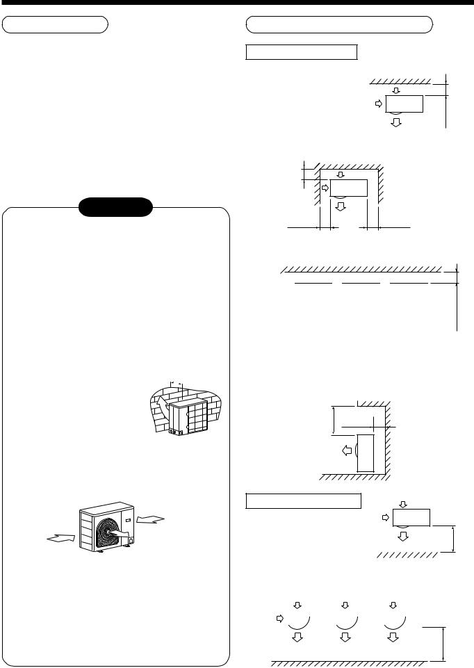
CAUTION
1.Install the outdoor unit at a place where discharge air is not blocked.
2.When an outdoor unit is installed in a place that is always exposed to a strong wind like a coast or on a high storey of a building, secure a normal fan operation by using a duct or a wind shield.
3.When installing the outdoor unit in a place that is constantly exposed to a strong wind such as the upper stairs or rooftop of a building, apply the windproof measures referring to the following examples.
1)Install the unit so that its
discharge port faces to the 500 wall of the building. Keep a
distance 500 mm or more
between the unit and the
wall surface. 
2)Supposing the wind direction during the operation season of the air conditioner, install the unit so that the discharge port is set at right angle to the wind direction.
Strong wind
Strong wind
4.Installation in the following places may result in some troubles. Do not install the unit in such places below.
•A place full of machine oil.
•A place full of sulphuric gas.
•A place where high-frequency radio waves are likely to be generated as from audio quipment, welders, and medical equipment.
Necessary Space for Installation
Obstacle at rear side
<Upper side is free>
1. Single unit installation
150 or more
2. Obstacles at both right and left sides.
200 ormore |
obstacle should be |
|
The height of the |
|
lower than the height |
|
of the outdoor unit. |
150 |
300 |
or more |
or more |
3. Serial installation of two or more units


 200 or more
150 |
300 |
300 |
300 |
or more |
or more |
or more |
or more |
The height of the obstacle should be lower than the height of the outdoor unit.
<Obstacle also at the upper side>
500 ormore |
150 |
or more |
|
|
Obstacle at front side
<Upper side is free>
1. |
Single unitIn installation |
|
500 moreor |
||||||
|
|
||||||||
|
|
|
|
|
|||||
2. |
Serial installation of two or more units |
|
|
||||||
|
|
|
|
|
|
|
|
|
|
|
|
|
|
|
|
|
|
|
|
1000 or more
4
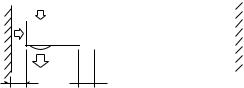
3 SELECTION OF INSTALLATION
<Obstacle also at the upper side>
1000 |
1000 moreor |
or more |
|
Obstacles at both front and rear sides
Open the upper side and both right and left sides. The height of obstacle at both front and rear side, should be lower than the height of the outdoor unit.
<Standard installation>
1. Single unit installation
1000 150 or more or more
2. Serial installation of two or more units
|
|
200 or more |
300 |
300 |
1000 moreor |
or more |
or more |
|
Installation of Outdoor Unit
•Before installation, check strength and horizontality of the base so that abnormal sound does not generate.
•According to the following base diagram, fix the base firmly with the anchor bolts.
(Anchor bolt, nut: M10 x 4 pairs)
<SM560AT-E>
|
90 |
600 |
90 |
|
|
115 |
|
330 |
310 |
76 |
|
Ø28 Drain hole
<SM800AT-E>
|
|
150 |
|
600 |
150 |
|
|
|
|
|
430 |
|
|
|
Drain hole |
40 |
|
|
|
|
|
|
|
400 |
365 |
Knockout hole |
Drain nipple mounting hole |
||
|
|
|
|
||
Set the out margin of the anchor bolt to 15mm or less.
15 or less
Serial installation at front and rear sides
Open the upper side and both right and left sides. The height of obstacle at both front and rear sides should be lower than the height of the outdoor unit.
<Standard installation>
•In case of drainning through the drain hose, attach the following drain nipple and the waterproof rubber cap, and use the drain hose (Inner diam.: 16mm) sold on the market. And also seal the screws securely with silicone material, etc. so that water does not drop down. Some conditions may cause dewing or dripping of water.
|
|
|
|
|
|
|
|
|
|
|
|
|
|
|
|
|
|
|
|
|
|
|
|
|
|
|
|
|
|
|
|
|
|
|
|
|
|
|
|
|
|
|
|
|
|
|
|
|
|
|
|
|
|
|
|
|
|
|
|
|
|
|
|
Drain nipple |
Waterproof rubber cap |
|||
|
|
|
|
|
|
|
|
|
|
|
|
|
|
|
|
|
|
|||||
1000 |
300 |
|
|
1500 |
|
2000 |
|
200 |
|
|||||||||||||
or more |
or more |
|
or more |
|
|
or more |
or more |
|
|
|
|
|
||||||||||
5
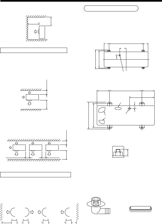
<SM560AT-E> |
Refrigerant Piping Connection |
|
 Waterproof rubber cap
Base plate
Drain nipple
<SM800AT-E>
Knockout hole
Open
Waterproof rubber cap

 Drain nipple
•When there is a possibility of freezing of drain at the cold district or a snowfall area, be careful for drainage ability of drain. The drainage ability increases when a knockout hole on the base plate is opened. (Open the knockout hole to outside using a screwdriver, etc.)
Optional Installation Parts
(Local Procure)
|
Parts name |
Q’ty |
|
|
|
|
|
A |
Refrigerant piping |
Each one |
|
Liquid side : Ø6.35 mm or Ø9.52 mm |
|||
|
Gas side : Ø12.7 mm or Ø15.9 mm |
|
|
|
|
|
|
B |
Pipe insulating material |
1 |
|
(polyethylene foam, 6 mm thick) |
|||
|
|
||
|
|
|
|
C |
Putty, PVC tapes |
Each one |
|
|
|
|
CAUTION
TAKE NOTICE THESE IMPORTANT
4 POINTS BELOW FOR PIPING WORK
1.Keep dust and moisture away from inside the connecting pipes.
2.Tightly connect the connection between pipes and the unit.
3.Evacuate the air in the connecting pipes using VACUUM PUMP.
4.Check gas leak at connected points.
<Piping connection>
Capacity |
Liquid side |
Gas side |
|||
rank |
|
|
|
|
|
Outer |
Thickness |
Outer |
Thickness |
||
RAV- |
|||||
diameter |
diameter |
||||
|
|
|
|
|
|
SM560 |
Ø6.4 |
0.8 |
Ø12.7 |
0.8 |
|
|
|
|
|
|
|
SM800 |
Ø9.5 |
0.8 |
Ø15.9 |
1.0 |
|
|
|
|
|
|
|
6
3 SELECTION OF INSTALLATION
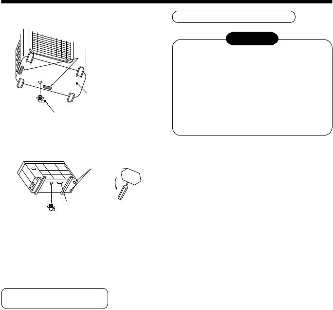
Knockout of Pipe Cover
<SM800AT-E>
Rear direction
Pipe cover
Side direction
Front direction
Down direction
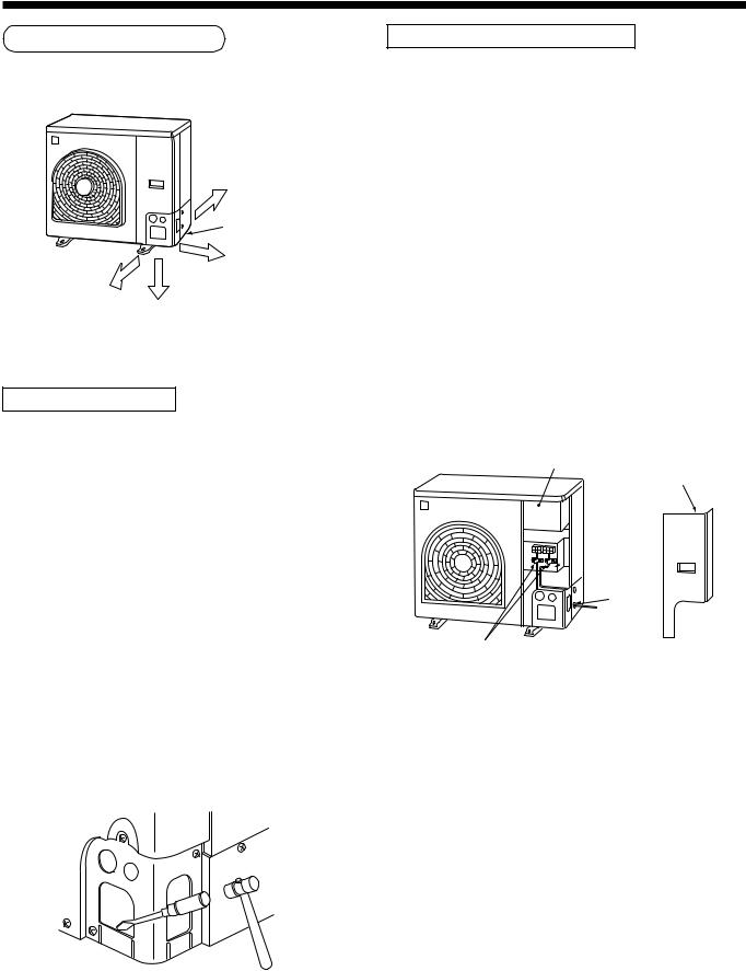
Knockout procedure
•The indoor/outdoor connecting pipes can be connected to 4 directions.
Take off the knockout part of the pipe cover in which pipes or wires pass through the base plate.
•As shown in the figure, do not remove the pipe cover from the cabinet so that the knockout hole can be easily punched. To knock out, it is easily taken off by hands by punching a position at the lower side of 3 connected parts with screwdriver along the guide line.
•After marking the knockout hole, remove the burr and mount the attached protective bush and guard material for pass-through part in order to protect pipes and wires.
After connecting the pipes, be sure to mount the pipe cover. The pipe cover is easily mounted by cutting off the slit at the lower part of the pipe cover.
How to remove the front panel
1.Remove screws of the front panel.
2.Pull the front panel downward.
Removing the front panel, the electric parts appear at the front side.
•The metal pipes are attachable to the piping holes. If the size of the used power pipe does not match with the hole, adjust the hole size to match with pipe size.
•Be sure to fix the power cable and indoor/outdoor connecting cable with bundling band sold on the market so that they do not make contact with the compressor and discharge pipe.
(Temperature of the compressor and discharge pipe becomes high.)
In order to avoid the force applied to on the connecting section, be sure to fix the cables to the cord clamps provided on the pipe valve fixing plate and the electric parts box.
Electric parts box
Front panel
Pipe valve
 fixing plate
 Piping
hole
Cord clamp
7
4 REFRIGERANT PIPING
Pipe Forming/End Positioning
<SM560AT-E>
•Forming of pipe
Form the pipe along with a marked line of the cabinet.
•End positioning of pipe
Match the ends of both pipes at at a distance of 85 mm apart from the marked line.
85mm
 Marked line
• Flaring size : A (Unit : mm)
|
A |
+0 |
|
Outer dia. of copper pipe |
- 0.4 |
||
|
|
||
R410A |
R22 |
||
|
|||
|
|
|
|
6.35 |
9.1 |
9.0 |
|
|
|
|
|
9.52 |
13.2 |
13.0 |
|
|
|
|
|
12.7 |
16.6 |
16.2 |
|
|
|
|
|
15.9 |
19.7 |
19.4 |
|
|
|
|
*In case of flaring for R410A with the conventional flare tool, pull it out approx. 0.5 mm more than that of R22 to adjust to the specified flare size. The copper pipe gauge is useful for adjusting projection margin
size.
A
Flaring
1. Cut the pipe with a pipe cutter.
90˚ |
Obliquity Roughness |
Warp |
2.Insert a flare nut into the pipe, and flare the pipe.
As the flaring sizes of R410A differ from those of refrigerant R22, the flare tools newly manufactured for R410A are recommended.
However, the conventional tools can be used by adjusting projection margin of the copper
pipe.
B |
• Projection margin in flaring : B (Unit : mm)
Rigid (Clutch type)
Outer dia. |
R410A tool used |
Conventional tool used |
|||
of copper |
|
|
|
|
|
R410A |
R22 |
R410A |
R22 |
||
pipe |
|||||
|
|
|
|
|
|
6.35 |
0 to 0.5 |
(Same as left) |
1.0 to 1.5 |
0.5 to 1.0 |
|
|
|
|
|
|
|
9.52 |
0 to 0.5 |
(Same as left) |
1.0 to 1.5 |
0.5 to 1.0 |
|
|
|
|
|
|
|
12.7 |
0 to 0.5 |
(Same as left) |
1.0 to 1.5 |
0.5 to 1.0 |
|
|
|
|
|
|
|
15.9 |
0 to 0.5 |
(Same as left) |
1.0 to 1.5 |
0.5 to 1.0 |
|
|
|
|
|
|
|
Imperial (Wing nut type)
Outer dia. of copper pipe |
R410A |
R22 |
|
|
|
6.35 |
1.5 to 2.0 |
1.0 to 1.5 |
|
|
|
9.52 |
1.5 to 2.0 |
1.0 to 1.5 |
|
|
|
12.7 |
2.0 to 2.5 |
1.5 to 2.0 |
|
|
|
15.9 |
2.0 to 2.5 |
1.5 to 2.0 |
|
|
|
8
4 REFRIGERANT PIPING
Tightening of Connecting Part
|
(Unit: N•m) |
|
|
Outer dia. of copper pipe |
Tightening torque |
|
|
6.35mm (diam.) |
14 to 18 (1.4 to 1.8kgf•m) |
|
|
9.52mm (diam.) |
33 to 42 (3.3 to 4.2kgf•m) |
|
|
12.7mm (diam.) |
50 to 62 (5.0 to 6.2kgf•m) |
|
|
15.9mm (diam.) |
63 to 77 (6.3 to 7.7kgf•m) |
|
|
Flare at
indoor unit side
Flare at
outdoor unit side
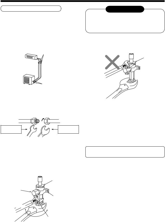
•Align the centers of the connecting pipes and tighten the flare nut strong as far as possible with your fingers.
Then fix the nut with a spanner and tighten it with torque wrench as shown in the figure.
Half union or packed valve |
Flare nut |
|
Externally |
|
Internally |
threaded side |
|
threaded side |
Fix with spanner. |
Tighten with torque wrench. |
|
•As shown in the figure, be sure to use a double spanner to loosen or tighten the flare nut of the valve at gas side. If using a single spanner, the nut cannot be tightened with necessary tightening torque.
On the contrary, use a single spanner to loosen or tighten the flare nut of the valve at liquid side.
REQUIREMENT
1.Do not put the spanner on the cap. The valve may be broken.
2.If applying excessive torque, the nut may be broken according to some installation conditions.
•After the installation work, be sure to check gas leak of connecting part of the pipes with nitrogen.
Cover
•Pressure of R410A is higher than that of R22 (Approx. 1.6 times). Therefore, using a torque wrench, tighten the flare pipe connecting sections which connect the indoor/outdoor units at the specified tightening torque. Incomplete connections may cause not only a gas leak, but also a trouble of the refrigeration cycle.
Do not apply refrigerating machine oil to the flared surface.
Cover
Cap
Piping valve
Loosened |
Tightened |
|
Flare nut |
SM800 type valve at gas side
9
5 EVACUATING
Air Purge
This air conditioner can be installed up to the connecting pipe length and height difference in the following table.
Capacity rank |
Max. connecting |
Height difference (m) |
Hexagonal |
||
|
|
||||
|
pipe length (m) |
Outdoor unit at upper side |
Outdoor unit at lower side |
wrench size |
|
|
|
|
|||
|
|
|
|
|
|
SM560 type |
30 |
30 |
15 |
4mm |
|
|
|
|
|
||
SM800 type |
50 |
30 |
15 |
||
|
|||||
|
|
|
|
|
|
With respect to the preservation of terrestrial environment, adopt “Vacuum pump” for air purge (Evacuate air in the connecting pipes) when installing the unit.
•Do not discharge the refrigerant gas to the atmosphere to preserve the terrestrial environment.
•Use a vacuum pump to discharge the air (nitrogen, etc.) remained in the set. If the air remains, the capacity may decrease.
For the vacuum pump, be sure to use one with backflow preventer so that the oil in the pump does not backflow into the pipe of the air conditioner when the pump stops. (If oil in the vacuum pump is put in an air conditioner including R410A, it may cause trouble on the refrigeration cycle.)
Vacuum pump
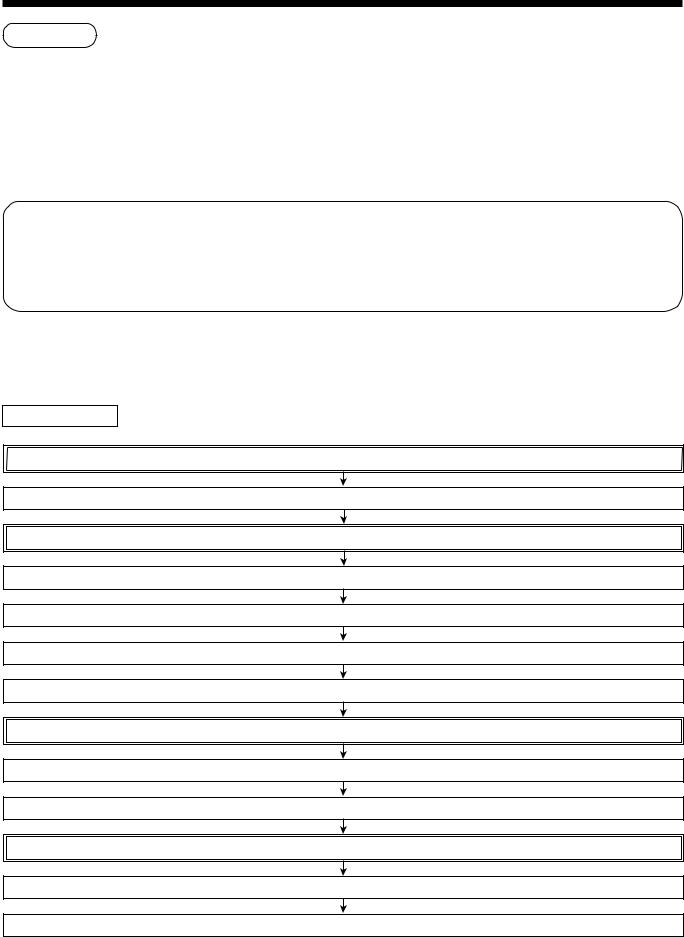
As shown in the right figure, connect the charge hose after the manifold valve are closed completely.
Attach the connecting port of the charge hose with a projection to push the valve core (setting pin) to the charge port of the set.
Open handle Low fully.
Turn ON the vacuum pump (*1)
Loosen the flare nut of the packed valve (Gas side) a little to check the air passes through. (*2)
Tighten the flare nut again.
Execute vacuuming until the compound pressure gauge indicates –101kPa (–76cmHg). (*1)
Close handle Low completely.
Turn OFF the vacuum pump.
Leave the vacuum pump as it is for 1 or 2 minutes, and check the indicator of the compound pressure gauge does not return.
Open fully the valve stem or the valve handle. (First, at liquid side, then gas side)
Disconnect the charge hose from the charge port.
Tighten valve and caps of the charge port surely.
10
5 EVACUATING
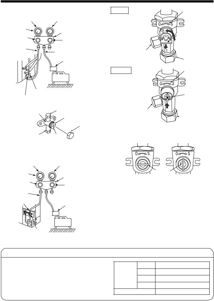
<SM560AT-E>
Compound pressure gauge |
Pressure gauge |
|
–101kPa |
|
|
(–76cmHg) |
Manifold valve |
|
|
||
Handle Lo |
Handle Hi |
|
|
(Keep fully closed) |
|
Charge hose |
Charge hose |
|
(For R410A only) |
||
(For R410A only) |
||
|
||
|
Vacuum pump adapter |
|
|
for counter-flow prevention |
|
|
(For R410A only) |
|
|
Vacuum |
|
|
pump |
Packed valve (Gas side)
Service port (Valve core (Setting pin))
Valve unit |
|
|
|
Flare nut |
|
|
|||
|
|
|
|
|
|
Stopper |
|
Charge cap |
Charge port |
Valve rod |
|
<SM800AT-E>
Compound pressure gauge |
Pressure gauge |
–101kPa |
|
(–76cmHg) |
Manifold valve |
|
Handle Lo
Charge hose (For R410A only)
Service port
(Valve core (Setting pin))
Handle Hi
(Keep fully closed)
Charge hose
 (For R410A only)
Vacuum pump adapter
for counter-flow prevention (For R410A only)
Vacuum
pump
Packed valve at gas side
OPEN
Charge port
Valve unit
Handle
Pull out the handle and using cutting pliers, etc. turn it counterclockwise by 90˚. (Open fully)
|
Flare nut |
CLOSE |
Valve unit |
|
Push in handle.
Charge port
 Flare nut
Handle position
Handle
Opened fully |
Closed completely |
*1. Use the vacuum pump, vacuum pump adapters, and gauge manifold referring to the manuals attached to each tool before using them. For the vacuum pump, check oil is filled up to the specified line of the oil gauge.
*2. While the air is purged, check again that the connecting port of charge hose, which has a projection to push the valve core, is firmly connected to the charge port.
Valve handling precautions
•Open the valve stem or the handle until it strikes the stopper. It is unnecessary to apply further force.
•Securely tighten the cap with a torque wrench.
•Cap tightening torque
Ø6.4 14 to 18N•m (1.4 to 1.8kgf•m)
Ø9.5 33 to 42N•m (3.3 to 4.2kgf•m)
Valve size
Ø12.7 33 to 42N•m (3.3 to 4.2kgf•m)
Ø15.9 20 to 25N•m (2.0 to 2.5kgf•m)
Charge port |
14 to 18N•m (1.4 to 1.8kgf•m) |
11
6 ELECTRICAL WORK
For the air conditioner that has no power cable, connect a power cable as mentioned below.
Model |
RAV- |
SM560AT-E |
SM800AT-E |
||
|
|
|
|
||
Power supply |
220 – 240 V |
||||
Single phase 50 Hz |
|||||
|
|
||||
|
|
|
|||
Maximum running current |
12A |
|
15A |
||
|
|
|
|
||
Installation fuse rating |
25 A (D type |
) |
|||
|
|
|
|||
Power cable |
H07 RN-F or 245 IEC 66 |
||||
(2.5 mm2 or more) |
|||||
|
|
|
|
|
|
CAUTION
•Wrong wiring may cause a burn-out to some electrical parts.
•Be sure to use the cord clamps attached to the product.
•Do not damage or scratch the conductive core and inner insulator of power and inter-connecting cables when peeling them.
•Be sure to comply with local regulations of the cable from outdoor unit to indoor unit.
(wire size and cabling method etc.)
•Use the power and Inter-connecting cables with specified thickness, specified type and protective devices required.
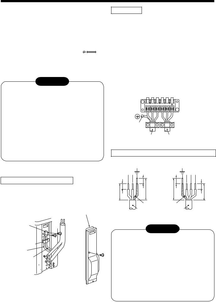
<SM560AT-E>
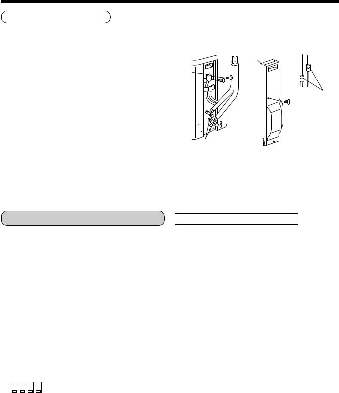
How to remove the valve cover
1.Remove screws of the valve cover.
2.Pull the valve cover downward to remove it.
Valve cover
Piping cover
Cord clamp
Indoor/outdoor connecting cables
Power cable
How to wire
1.Connect the connecting cable to the terminal as identified with their respective numbers on the terminal block of indoor and outdoor unit.
H07 RN-F or 245 IEC 66 (1.0 mm2 or more)
2.When connecting the connecting cable to the outdoor unit terminal, prevent water coming in the outdoor unit.
3.Insulate the unsheathed cords (conductors) with electrical insulation tape. Process them so that they do not touch any electrical or metal parts.
4.For inter connecting cable, do not use a wire jointed to another on the way.
Use wires long enough to cover the entire length.
Terminal block
1 2 3 L N
Screw
Connecting Power cable cable
Stripping length power cord and connecting cable
L N |
10 |
10 |
1 2 3 |
10 |
|
|
10 |
40 |
40 |
30 |
30 |
Earth line |
Earth line |
(mm) |
|
|
|
Power cable |
Connecting |
|
|
cable |
|
CAUTION
•The installation fuse (25A D type  ) must be used for the power supply line of this air conditioner.
•Incorrect/incomplete wiring might cause an electrical fire or smoke.
•Prepare the exclusive power supply for the air conditioner.
•This product can be connected to the mains. Connection to the fixed wiring :
A switch which disconnects all poles and has a contact separation of at least 3 mm must be incorporated in the fixed wiring.
12
7 FINAL INSTALLATION CHECKS
Check and Test Operation
For R410A, use the leak detector exclusively manufactured for HFC refrigerant (R410A, R134a, etc.).
*The conventional leak detector for HCFC refrigerant (R22, etc.) cannot be used because its sensitivity for HFC refrigerant lowers to approx. 1/40.
•Pressure of R410A is approx. 1.6 times higher than that of R22.
If installation work is incompletely finished, a gas leakage may occur when pressure rises during operation.
Therefore, be sure to test the piping connections for leakage.
•Check gas leakage at the flare nut connections, valve stem cap connections and service port cap fittings with a leak detector or soap water.
Valve cover
Piping cover
Check points of outdoor unit
Flare nut connections (Indoor unit)
Useful Functions (SM800AT-E only)
Self-Diagnosis by LED Indication
In addition to the code checking by remote controller of the indoor unit, troubles of the outdoor unit can be diagnosed by LED indications on the cycle control P.C. board of the outdoor unit. Utilize them for various checks. For the check by remote controller of the indoor unit, refer to the Installation Manual of the indoor unit.
Before a check, confirm each bit of the DIP switch is set to OFF position.
LED indication and code checking
|
DIP switch |
Cycle control P.C. board |
|
|
|
|||||
|
LED indication |
Cause |
|
|
||||||
|
SW800 |
|
|
|
|
|||||
|
|
|
D800 |
D801 |
D802 |
D803 |
|
|
|
|
|
|
|
|
|
|
|
||||
|
|
|
|
¡ |
l |
l |
l |
Heat exchanger sensor (TE) error |
|
|
|
|
|
|
|
|
|
|
|
|
|
|
|
|
|
l |
l |
¡ |
l |
Suction sensor (TS) error |
|
|
|
|
|
|
|
|
|
|
|
|
|
|
|
|
|
¡ |
¡ |
l |
l |
Discharge sensor (TD) error |
|
|
|
|
|
|
|
|
|
|
|
|
|
|
|
|
|
l |
¡ |
l |
¡ |
High-pressure protection error |
|
|
|
|
|
|
|
|
|
|
|
|
|
|
|
|
|
l |
¡ |
l |
l |
Outdoor temperature sensor (TO) error |
LED |
|
|
|
|
|
|
|
|
|
|
||
|
|
|
|
¡ |
¡ |
¡ |
l |
DC outside fan error |
||
|
|
|
|
indication |
||||||
|
|
|
|
|
|
|
|
|
||
|
|
|
|
¡ |
l |
l |
¡ |
Communication error between IPDU |
||
|
|
|
|
D800 |
|
|||||
|
|
|
|
|
|
|
|
|
: Red |
|
|
|
|
|
l |
¡ |
¡ |
l |
Discharge temp. error |
||
|
ON |
|
|
¡ |
||||||
|
|
|
|
|
|
|
|
|
||
|
|
¡ |
¡ |
l |
¡ |
EEPROM error |
|
|||
|
|
|
|
D801 |
: Yellow |
|||||
|
|
|
|
|
|
|
|
|
||
|
1 2 3 |
4 |
|
l |
l |
|
|
Communication error between IPDU |
||
|
|
|
|
¡ |
¡ |
¡ |
|
|||
|
|
|
|
|
||||||
|
|
|
|
¥ |
l |
l |
l |
G-Tr short-circuit protection |
D802 |
: Yellow |
|
|
|
|
l |
¥ |
l |
l |
Detect circuit error |
¡ |
|
|
|
|
|
D803 |
|
|||||
|
|
|
|
|
|
|
|
|
: Yellow |
|
|
|
|
|
¥ |
¥ |
l |
l |
Current sensor error |
||
|
|
|
|
|
|
|
|
|
¡ |
|
|
|
|
|
l |
l |
¥ |
l |
Comp. lock error |
|
|
|
|
|
|
|
|
|||||
|
|
|
|
|
|
|
|
|
|
|
|
|
|
|
¥ |
l |
¥ |
l |
Comp. break down |
¥ : Rapid flash |
|
|
|
|
|
l |
l |
l |
¥ |
Phase missing detection, Detection of coming-off of CT current sensor |
l : Go off |
|
|
|
|
|
|
|
|
|
|
¡ : Go on |
|
|
|
|
|
l |
¡ |
l |
¡ |
Serial communication error by thermo. operation of Comp. case |
||
|
|
|
|
|
|
|
|
|
|
|
13
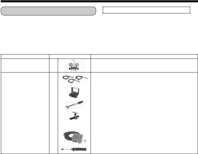
Installation/Servicing Tools |
Changes in the product and components |
In the case of an air conditioner using R410A, in order to prevent any other refrigerant from being charged accidentally, service port diameter of the outdoor unit control valve (3 way valve) has been changed. (1/2 UNF 20 threads per inch)
•In order to increase the pressure resisting strength of the refrigerant piping flare processing diameter and size of opposite side of flare nuts has been changed. (for copper pipes with nominal dimensions 1/2 and 5/8)
New tools for R410A
New tools for R410A |
Applicable to R22 model |
Changes |
|
× |
As pressure is high, it is impossible to measure by means of conventional |
Gauge manifold |
|
gauge. In order to prevent any other refrigerant from being charged, each |
|
|
port diameter is changed. |
|
× |
|
In order to increase pressure resisting strength, hose materials and port |
Charge hose |
|
|
size are changed (to 1/2 UNF 20 threads per inch). |
|
|
|
When purchasing a charge hose, be sure to check the port size. |
|
|
|
|
Electronic balance |
¡ |
|
As pressure is high and gasification speed is fast, it is difficult to read the |
for refrigerant charging |
|
indicated value by means of charging cylinder, as air bubbles occur. |
|
|
|
||
|
|
|
|
Torque wrench |
× |
|
The size of opposite sides of flare nuts have been increased. Incidentally, |
(nominal diam. 1/2, 5/8) |
|
a common wrench is used for nominal diameters 1/4 and 3/8. |
|
|
|
|
|
Flare tool |
¡ |
|
By increasing the clamp bar’s receiving hole, strength of spring in the tool |
(clutch type) |
|
has been improved. |
|
|
|
||
|
|
|
|
Gauge for projection adjustment |
— |
— |
Used when flare is made with using conventional flare tool. |
|
|
|
|
|
|
|
Connected to the conventional vacuum pump. It is necessary to use an |
|
|
|
adapter to prevent vacuum pump oil from flowing back to the charge hose. |
Vacuum pump adapter |
¡ |
|
The charge hose connecting part has two ports-one for conventional |
|
refrigerant (7/16 UNF 20 threads per inch) and one for R410A. |
||
|
|
|
|
|
|
|
If the vacuum pump oil (mineral) mixes with R410A a sludge may occur |
|
|
|
and damage the equipment. |
Gas leakage detector |
× |
X |
Exclusive for HFC refrigerant. |
|
•Incidentally, the “refrigerant cylinder” comes with the refrigerant designation (R410A) and protector coating in the U,S.’s ARI specified rose color (ARI color code: PMS 507).
•Also, the “charge port and packing for refrigerant cylinder” require 1/2 UNF 20 threads per inch corresponding to the charge hose’s port size.
14
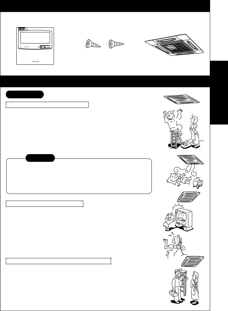
ACCESSORIES
Remote controller |
|
Screws (two pcs.) |
|
Standard 4-way cassette |
|
|
|
|
panel optional parts |
|
|
|
|
|
|
|
|
|
|
PRECAUTIONS FOR SAFETY
WARNING 
WARNINGS ABOUT INSTALLATION
• Make sure to ask the qualified installation professional in electric work to install the air conditioner.
If the air conditioner is inappropriate installed by yourself, it may cause water leak, electric shock, fire, and so on.
•Ground the air conditioner without fail.
Do not connect the ground wire to gas pipe, water pipe, lightning rod or ground
wire of telephone. If the air conditioner is imperfectly grounded, it may cause electric shock.
CAUTION
TO DISCONNECT THE APPLIANCE FROM THE MAINS SUPPLY
This appliance must be connected to the mains by means of a switch with a contact separation of at least 3 mm.
The installation fuse (25A D type  ) must be used for the power supply line of this conditioner.
WARNINGS ABOUR OPERATION
• Avoid cooling the room too strong or exposing the human body to cool breeze for a long time as it is bad for the health.
• When you notice something abnormal with the air conditioner (smells like something scorching, poor cooling, etc.), immediately turn off the main switch, the circuit breaker, from the mains to stop the air conditioner, and contact the dealer.
If the air conditioner is continuously operated with something abnormal, it may cause machine failure, electric shock, fire, and so on.
WARNINGS ABOUT MOVEMENT AND REPAIR
• Do not move or repair any unit by yourself.
Since there is high voltage inside the unit, you may get electric shock when removing the cover and main unit.
• Whenever the air conditioner needs repair, make sure to ask the dealer to do it. If it is repaired imperfectly, it may cause electric shock or fire.
• When moving the air conditioner for re-installing at another place, ask the dealer to do it. If it is imperfectly installed, it may cause electric shock or fire.
RAV-SM560UT-E RAV-SM800UT-E
15

RAV-SM560UT-E RAV-SM800UT-E
CAUTION
CAUTIONS ABOUT INSTALLATION
•Certainly lay the drain hose for perfect draining.
Bad drainage may cause flooding in the house and getting furniture wet.
•Make sure to connect the air conditioner to an exclusive AC outlet of the rated voltage, otherwise the unit may break down or cause a fire.
•Do not install the unit in a place where inflammable gas may leak. If inflammable gas accumulates around the unit, it may cause a fire.
CAUTIONS ABOUT OPERATION
•Carefully read this manual before starting the air conditioner.
There are many important things to keep in mind for daily operation.
•Do not use this air conditioner for special purpose such as preserving food, precision instruments, art objects, breeding animals, growing potted plants, etc.
•Avoid exposing potted plants and animals to the wind of the air conditioner, since it badly affects the health and growth of them.
•When the air conditioner is operated with a combustion appliance in the same place, be careful of ventilation to let fresh air enter the room.
Poor ventilation causes oxygen shortage.
•When the air conditioner is used in a closed room, be careful of sufficient ventilation of the room. Poor ventilation causes oxygen shortage.
•Do not touch any switches with wet finger, otherwise you may get an electric shock.
•Do not place any combustion appliance in a place where it is directly exposed to the wind of air conditioner, otherwise it may cause imperfect combustion.
•If the air conditioner won’t be used for a considerably long time, turn off the main switch or the circuit breaker, for safety. Disconnect from the power supply prevents the unit from lightning and power supply surge.
•Check the concrete blocks, etc. of the base of the outdoor unit occasionally.
If the base is left damaged or deteriorated, the unit may topple over and inflict an injury to a person as the worst case.
•When cleaning the unit, make sure to turn off the main switch or the circuit breaker beforehand for preventing you from getting injured by the electric fan running inside. For details of cleaning method, refer to “Maintenance” on page 10.
•Do not put anything on the outdoor unit nor step onto it. If you do so, it may not only topple over the unit but also injure yourself.
•To make the air conditioner operate in its original performance, operate it within the range of the operating temperature specified in the instructions.
Otherwise it may cause a malfunction, or water leak from the unit.
•Prevent any liquid from falling into the remote controller. Do not spill juice, water or any kind of liquid.
16

PARTS NAME
Indoor unit
Button |
Button to open/close the |
suction port |
Earth screw
Provided in the electric parts box
Air filter
Removes dust or trash. (Provided on the suction port.)
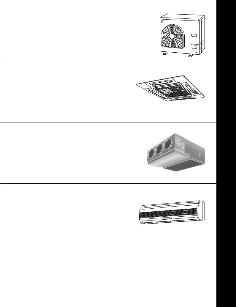
Outdoor unit
Air inlet (Side and rear)
Discharge flap of discharge port
Change the direction of the air to be discharged according to cool/heat mode.
Suction air port
The air in the room is sucked in from this port.
Projection of air filter
Remote controller
REMOTE CONTROLLER
Air outlet |
Pipes and electric wires |
RAV-SM560UT-E RAV-SM800UT-E
17
RAV-SM560UT-E RAV-SM800UT-E
PARTS NAME OF REMOTE CONTROLLER
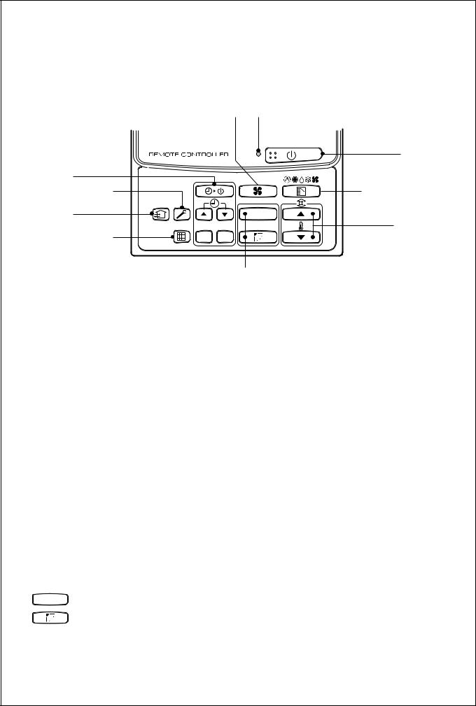
Display section
In the display example, all indicators are displayed for the explanation.
In reality only, the selected contents are indicated.
•When turning on the leak breaker at the first time, [SET DATA] flashes on the display part of the remote controller. While this display is flashing, the model is being automatically confirmed. Accordingly, wait for a while after [SET DATA] display has disappeared, and then use the remote controller.
 CODE No.
SET DATA
UNIT No.


 SETTINGTEST R.C. No.
UNIT
SET CL
Display section
Operation section
|
|
1 8 |
|
|
|
2 |
|
|
|
CODE No. |
9 |
|
3 |
|
|
|
|
4 |
SET DATA |
|
10 |
|
|
|
|
|
|
||
|
|
UNIT No. |
|
|
|
5 |
SETTINGTEST |
R.C. No. |
|
11 |
|
|
12 |
||||
|
|
|
|||
|
6 |
|
|
13 |
|
7 |
|
|
|
14 |
|
1 SET DATA display
Displayed during setup of the timer.
2 Operation mode select display
The selected operation mode is displayed.
3 CHECK display
Displayed while the protective device works or a trouble occurs.
4 Timer time display
Time of the timer is displayed.
(When a trouble occurs, the check code is displayed.)
5 Timer SETIN setup display
When pushing the Timer SETIN button, the display of the timer is selected in order of [OFF]
→  [OFF] repeat OFF timer → [ON]
→ No display.
6 Filter display
If “FILTER  ” is displayed, clean the air filter.
7 TEST run display
Displayed during a test run.
8 Flap position display
Displays flap position.
9 SWING display
Displayed during up/down movement of the flap.
10 Set up temperature display
The selected set up temp. is displayed.
11 Remote controller sensor display
Displayed while the sensor of the remote controller is used.
12 PRE-HEAT display
Displayed when the heating operation starts or defrost operation is carried out.
While this indication is displayed, the indoor fan stops or the mode enters in LOW.
13 No function display
Displayed if there is no function even if the button is pushed.
14 Air volume select display
The selected air volume mode is displayed.
(AUTO) (HIGH) (MED.)
(LOW)
18
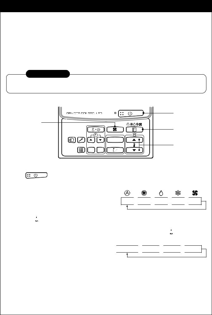
Operation section
Push each button to select a desired operation.
•The details of the operation needs to be set up once, afterward, the air conditioner can be used by pushing  button only.
|
|
1 |
7 |
2 |
|
|
8 |
|
|
9 |
|
3 |
|
|
|
4 |
|
|
UNIT |
5 |
SET |
CL |
10 |
|
|||
|
|
||
|
|
6 |
|
1 Air volume select button
Selects the desired air volume mode.
2 Timer set button
TIMER SET button is used when the timer is set up.
3 Check button
The CHECK button is used for the check operation. During normal operation, do not use this button.
4 Fan button
FAN button is used when a fan which is sold on the market or etc. is connected.
•If “No function” is displayed on the remote controller when pushing the FAN button, a fan is not connected.
5 Filter reset button
Resets (Erases) “FILTER  ” display.
6 UNIT and AUTO flap button
UNIT (No function)
7 Operation lamp
Lamp is lit during the operation. Lamp is off when stopped.
Although it flashes when operating the protection device or abnormal time.
8  button
When the button is pushed, the operation starts, and it stops by pushing the button again.
When the operation has stopped, the operation lamp and all the displays disappear.
9 Operation select button
Selects desired operation mode.
10 Set up temperature button
Adjusts the room temperature.
Set the desired set temperature by pushing  or
or  .
.
OPTION :
Remote controller sensor
Usually the TEMP. sensor of the indoor unit senses the temperature. The temperature on the surrounding of the remote controller can also be sensed.
For details, contact the dealer from which you have purchased the air conditioner.
19
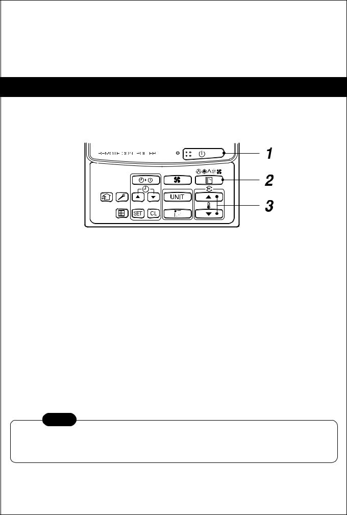
CORRECT USAGE
When you use the air conditioner for the first time or when you change the SET DATA value, follow the procedure below. From the next time, the operation displayed on the remote controller will start by pushing the  button only.
Preparation
Turn on the main power switch and/or the leakage breaker.
• When the power supply is turned on, a partition line is displayed on the display part of the remote controller.
*After the power supply is turned on, the remote controller does not accept an operation for approx. 1 minute, but it is not a failure.
REQUIREMENT
•While using the air conditioner, operate it only with  button without turning off the main power switch and the leak breaker.
3
UNIT
SET CL
1 Push |
button. |
1
2
4
The operation lamp goes on, and the operation starts.
2 Select an operation mode with the “MODE” button.
One push of the button, and the display changes in the order shown on the right.
AUTO 
 HEAT
HEAT 
 DRY
DRY 
 COOL
COOL 
 FAN
FAN
•In HEAT 
 mode, if the room temperature reaches to the set temperature, the outdoor unit stops and the air flow becomes LOW and the air volume decreases.
•In the defrost mode, the fan stops so that cool air is not discharged and PRE-DEF  is displayed.
3 Select air volume with “FAN  ” button.
One push of the button, and the display changes in the order shown on the right.

 AUTO
AUTO 

 HIGH
HIGH 

 MED.
MED. 

 LOW
LOW
•When air volume is “AUTO  ”, air volume differs according to the room temperature.
•In DRY  mode, “AUTO
  ” is displayed and the air volume is LOW.
•In heating operation, if the room temperature is not heated sufficiently with VOLUME “LOW ” operation, select “MED.
 ” or “HIGH
  ” operation.
4 Determine the set up temperature by pushing the “TEMP.  ” or “TEMP.
  ” button.
20
Stop
Push  button.
The operation lamp goes off, and the operation stops.
AUTOMATIC OPERATION (Auto Changeover)
When you set the air conditioner in  mode or switch over from AUTO operation because of some settings change, it will automatically select either cooling, heating, or fan only operation depending on the indoor temperature.
Start
1
2
 button
Push this button to start the air conditioner.
Mode select button (MODE)
Select Auto.
3 Temperature button
Set the desired temperature.
•In case of cooling, start the operation after approx. 1 minute.
•In case of heating, the operation mode is selected in accordance with the room temperature and operation starts after approximately 3 to 5 minutes.
•When you select the Auto mode, it is unnecessary to set the fan speed. The FAN speed display will show AUTO and the fan speed will be automatically controlled.
•After the heating operation has stopped, FAN operation may continue for approx. 30 seconds.
•When the room temperature reaches the set temperature and the outdoor unit stops, the supper low wind is discharged and the air volume decreases excessively. During defrost operation, the fan stops so that cool air is not discharged and “HEAT READY” is displayed.
•If the Auto mode is uncomfortable, you can select the desired conditions manually.
NOTE
When restarting the operation after stop
•When restarting the operation immediately after stop, the air conditioner does not operate for approx. 3 minutes to protect the machine.
Stop
Push  button.
Push this button again to stop the air conditioner.
21
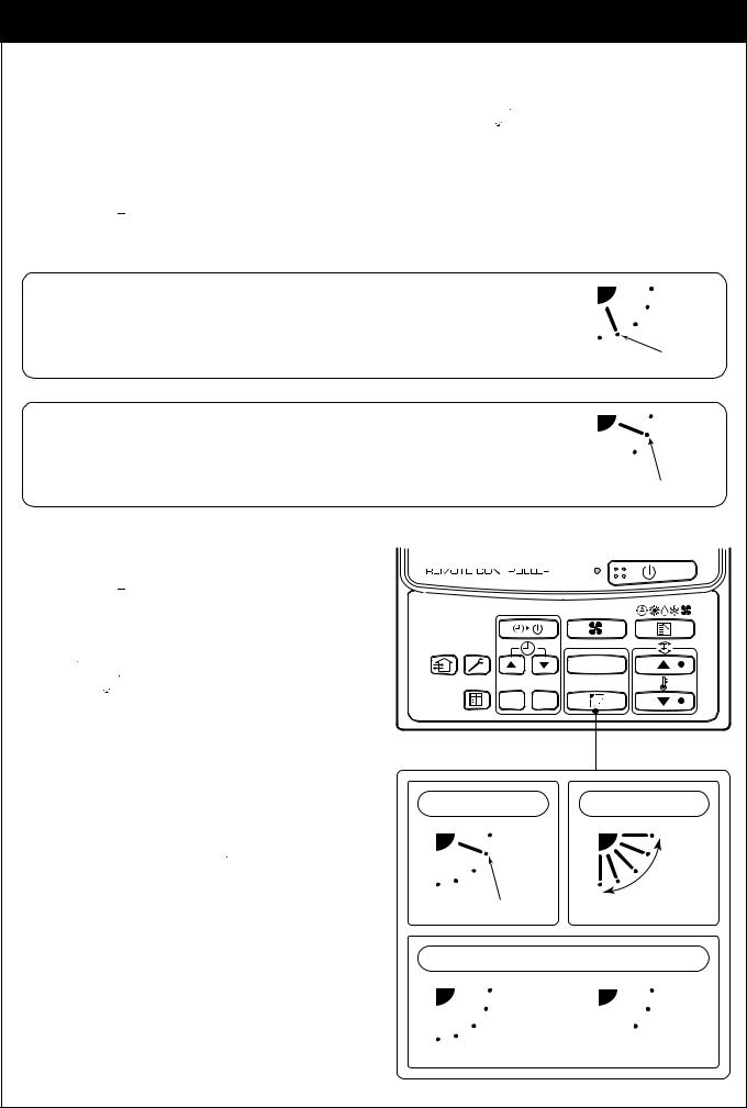
ADJUSTMENT OF WIND DIRECTIONd
•When the air conditioner stops, the flap (adjustment plate of up/down wind direction) directs downward automatically.
•When the heating operation is in READY states, the flap (adjustment plate of up/down wind direction) directs upward. The swinging starts after HEAT READY status cleared, SWING
 is displayed on the remote controller even if the heating operation is in READY status.
How to set up the wind direction
1 Push  during operation.
The wind direction changes for every push of the button.
In HEAT operation
Direct the flap (adjustment plate of up/down wind direction) downward. If directing at upward, hot air may not come to the foot.
Initial setup
In COOL/DRY operation
Direct the flap (adjustment plate of up/down wind direction) upward. If directing it downward, the dew may from on the surface of the air discharge port and may
drop down.
Initial setup
How to start swinging
1 Push  , set the flap (adjustment
plate of up/down wind direction) direction to the lowest position, and then push  again.
SWING 

 is displayed and the up/down wind direction is automatically selected.
How to stop swinging
1 Push SWING/WIND again while the flap is swinging.
•The flap stops at a position when you push.
After then, if pushing  , the wind direction descends from the highest position.
•In COOL/DRY operation, the flap does not stop as it directs downward. If stopping the flap as it directs downward during swing operation, it stops after moving to the 3rd position from the highest position.
UNIT
SET CL
In FAN operation |
In all modes |
Series of operation
Initial setup
Display when stopping the swing
Fan/Heat |
Cool/Dry |
operation |
operation |
22
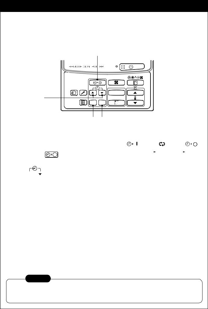
TIMER OPERATION
A type of timer operation can be selected from the following three types.
OFF timer |
: The operation stops when the time of timer has reached the set time. |
Repeat OFF timer |
: Every time, the operation stops after the set time has passed. |
ON timer |
: The operation starts when the time of timer has reached the set time. |
Timer operation |
1 |
|
UNIT
2
SET CL
3 4
1 Push TIMER SET button.
2
3
•The timer display (type) changes for every push of the button.
• SET DATA and |
display flashes. |
|
OFF |
|
|
|
|
OFF |
|
|
|
ON |
|
|
|
|
|
|
|
|
|
|
|
||||||
|
|
|
|
|
|
|
|
|
|
|
|
|||
(OFF timer) |
(Repeat OFF timer) |
(ON timer) |
||||||||||||
|
|
|||||||||||||
|
|
|
|
|
|
No display |
|
|
|
|
||||
|
|
|
|
|
|
|
|
|
|
|||||
Push  to select “SET TIME”.
For every push of  button, the set time increases in the unit of 0.5 hr (30 minutes). The maximum set time is 72.0 hr.
For every push of  button, the set time decreases in the unit of 0.5 hr (30 minutes). The minimum set time is 0.5 hr.
Push SET button.
•SET DATA display disappears and  display goes on.
(When ON timer is activated, time is displayed, and after time of the timer has been up, displays other than ON disappear.)
Cancel of timer operation
4 Push CL button.
• TIMER display disappears.
NOTICE
•When the operation stops after the timer reached the preset time, the Repeat OFF timer resumes the
operation by pushing  button and stops the operation after the time of the timer has reached the set time.
23
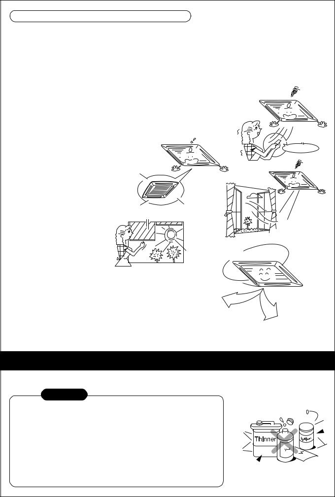
HINTS FOR ECONOMICAL OPERATION
Maintain room temperature at comfortable level
Clean air filters
The clogged air filter impairs the performance of the air conditioner.
Clean them every 2 weeks.
Never open doors and windows more often than necessary
To keep cool or warm air in the room, never open doors and windows more often than necessary.
Window curtains
In cooling, close the curtains to avoid direct sunlight.
In heating, close the curtains to keep the heat in.
Get uniform circulation of room air
Adjust the air flow direction for the even circulation of room air.
Clean, please.
Gee, chilly
Control
Please |
close |
|
Blows upward
Air flow adjustment
Cool and dry air
Warm
air
Blows downward
MAINTENANCE
Cleaning of remote controller
CAUTION
•Use a dry cloth to wipe the remote controller.
•A cloth dampened with cold water may be used on the indoor unit if
it is very dirty.
•Never use a damp cloth on the remote controller.
•Do not use a chemically-treated duster for wiping or leave such
materials on the unit for long. It may damage or fade the surface of the unit.
•Do not use benzine, thinner, polishing powder, or similar solvents for cleaning. These may cause the plastic surface to crack or deform.
24
If you do not plan to use the unit for more than 1 month
(1)Operate the fan for 3 to 4 hours to dry inside the unit
• Operate “FAN ONLY” mode with set temperature 30°C.
(2)Stop the air conditioner and turn off the main power switch or the circuit breaker.
Checks before operation
(1)Check that the air filters are installed.
(2)Check that the air outlet or inlet is not blocked.
(3)Turn on the main power switch or the circuit breaker for the mains AC outlet to turn on the air conditioner.
FAN ONLY operation or thermo.-off operation
WARNING
Make sure to ask the qualified maintenance professional for cleaning.
Turn off the main power supply switch or breaker before the unit maintenance.
Before maintenance, be sure to turn off the leakage breaker.
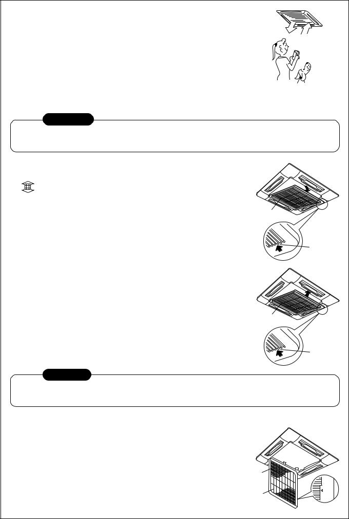
Cleaning of air filter
• |
If |
is displayed on the remote controller, maintain the air filter. |
• |
Clogging of the air filter reduce cooling/heating performance. |
|
Cleaning of panel and air filter |
Suction grille |
|
|
Preparation : |
|
1. Turn off the air conditioner by the remote controller.
2. Open the suction air port. |
Button |
|
•Slide the button of the suction air port inward, and open the suction port slowly while holding it.
Clean the panel and air filter with water:
• Wipe down the panel and air filter with a sponge or towel moistened with a kitchen detergent. (Do not use any metallic brush for cleaning.)
• Carefully rinse the panel and air filter to wash out the detergent.
• After rinsing the panel and air filter with water, dry it in the shade. |
Suction grille |
|
|
3. Close the suction air port. |
|
• Close the suction air port, slide the button outward, and fix the |
Button |
suction port securely. |
|
CAUTION
• Do not start the air conditioner while leaving the panel and air filter removed.
• Push the filter reset button. ( indication will be turn off.)
Cleaning of Air Filters
•Recommended cleaning intervals: Every two weeks.
•If the air filters are not cleaned, it not only reduce the cooling a performance of air conditioner but causes a failure in the air conditioner such as water falling in drops.
Preparation :
1.Stop the operation by remote controller.
2.Dismount the air filter.
Strap to prevent falling
Air filter
Push
25
Use a vacuum cleaner to remove dust from the filters or wash them with water.
•After rinsing the air filters with water, dry them in the shade.
•Set the air filter into the air conditioner.
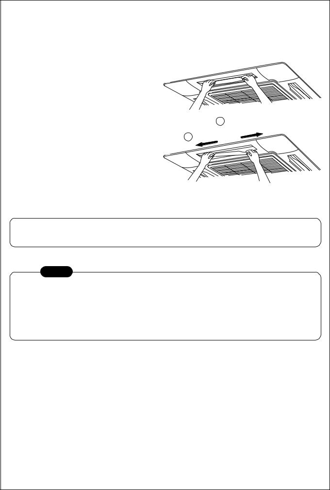
Cleaning of discharge flap
The discharge flap can be removed to clean.
1. Remove the discharge flap.
• Holding the both ends of the discharge flap, remove the flap sagging the center downward.
2. Cleaning with water |
|
• If the dirt is terrible, clean the flap by tepid |
|
water with neutral detergent or water. |
1 Insert |
3. Mount the discharge flap.
•First push in one side of the flap, and then insert the other side sagging the center downward.
2Insert in the flap sagging down the center downward.
Be careful to the direction of the flap when mounting.
Mount the flap so that the side with the mark faces upward and the arrow direction of the mark directs.
NOTE
For Air conditioning system which is operated regularly, cleaning and maintenance of the indoor/outdoor units are strongly recommended.
As a general rule, if an indoor unit is operated for about 8 hours daily, the indoor/outdoor units will need to be cleaned at least once every 3-MONTH. This cleaning and maintenance shall be carried out by a qualified person.
Failure to clean the indoor/outdoor units regularly will result in poor performance, icing, water leaking and even compressor failure.
26

AIR CONDITIONER OPERATIONS AND PERFORMANCE
3 minutes protection function
3-minutes protection function prevents the air conditioner from starting for initial 3 minutes after the main power switch/circuit breaker is turned on for re-starting the air conditioner.
Power failure
Power failure during operation will stop the unit completely.
•To restart the operation, push the START/STOP button on the remote controller.
•Lightning or a wireless car telephone operating nearby may cause the unit to malfunction. Turn off the main power switch or circuit breaker and then turn them on again. Push the START/STOP button on the remote controller to restart.
Heating characteristics
Preheating operation
The air conditioner will not deliver warm air immediately after it is turned on. Warm air will start to flow out after approximately 5 minutes when the indoor heat exchanger warmed up.
Warm air control (In heating operation)
When the room temperature reaches the set temperature, the fan speed is automatically reduced to prevent to blow cold draft. At this time, the outdoor unit will stop.
Defrosting operation
If the outdoor unit is frosted during the heating operation, defrosting starts automatically (for approximately 2 to 10 minutes) to maintain the heating capacity.
•The fans in both indoor and outdoor units will stop during the defrosting operation.
•During the defrosting operation, the defrosted water will be drained from the bottom plate of the outdoor unit.
Heating capacity
In the heating operation, the heat is absorbed from the outside and brought into the room. This way of heating is called heat pump system. When the outside temperature is too low, it is recommended to use another heating apparatus in combination with the air conditioner.
Attention to snowfall and freeze on the outdoor unit
•In snowy areas, the air inlet and air outlet of the outdoor unit are often covered with snow or frozen up. If snow or freeze on the outdoor unit is left as it is, it may cause machine failure or poor warming.
•In cold areas, pay attention to the drain hose so that it perfectly drains water without water remaining inside for freeze prevention. If water freezes in the drain hose or inside the outdoor unit, it may cause machine failure or poor warming.
Air conditioner operating conditions
For proper performance, operate the air conditioner under the following temperature conditions:
Cooling |
Outdoor temperature |
: –5°C to 43°C |
|
operation |
|
|
|
Room temperature |
: 21°C to 32°C (Dry valve temp.), 15°C to 24°C (Wet valve temp.) |
||
|
|||
|
|
||
|
CAUTION Room relative humidity – less than 80 %. If the air conditioner operates |
||
|
in excess of this figure, the surface of the air conditioner may cause dewing. |
||
Dry operation |
Outdoor temperature |
: 15°C to 43°C (Maximum suction air temp. 46°C) |
|
|
|
|
|
|
Room temperature |
: 17°C to 32°C |
|
|
|
|
|
Heating |
Outdoor temperature |
: –15°C to 15°C (Wet valve temp.) |
|
operation |
|
|
|
Room temperature |
: 15°C to 28°C (Dry valve temp.) |
||
|
|||
|
|
|
|
If air conditioner is used outside of the above conditions, safety protection may work.
27
 Loading...