


B-SA4T
Table of contents
 Loading...
PRINTED IN JAPAN
TOSHIBA Thermal Printer
B-SA4T SERIES
Document No. EO15-33001A
Original Jul., 2005
(Revised Sep., 2005)
Option Installation Manual

EO15-33001A
(Revision Date: Feb. 14, 2008)
TABLE OF CONTENTS
Page
1. Cutter Module------------------------------------------------------------------------------------------------------1- 1
1.1 B-SA204-QM/ B-SA204-QM-R ----------------------------------------------------------------------------1- 1
1.2 B-SA204P-QM-R----------------------------------------------------------------------------------------------1- 4
2. Strip Module--------------------------------------------------------------------------------------------------------2- 1
2.1 B-SA904-H-QM-R---------------------------------------------------------------------------------------------2- 1
2.2 B-SA904P-H-QM-R-------------------------------------------------------------------------------------------2- 5
3. Wireless LAN Module: B-SA704-WLAN-QM-------------------------------------------------------------3- 1
4. Serial Interface Board: B-SA704-RS-QM-R --------------------------------------------------------------4- 1
5. 300 dpi Print Head Kit: B-SA704-TPH3-QM-R-----------------------------------------------------------5- 1
6. Real Time Clock: B-SA704-RTC-QM-R --------------------------------------------------------------------6- 1
7. Expansion I/O Board: B-SA704-IO-QM-R-----------------------------------------------------------------7- 1
8. RFID Module: B-SA704-RFID-U2-EU-R--------------------------------------------------------------------8- 1
CAUTION!
1. This manual may not be copied in whole or in part without prior written permission of TOSHIBA
TEC.
2. The contents of this manual may be changed without notification.
3. Please refer to your local Authorised Service representative with regard to any queries you
may have in this manual.
Copyright © 2005
by TOSHIBA TEC CORPORATION
A
ll Rights Reserved
570 Ohito, Izunokuni-shi, Shizuoka-ken, JAPAN
INSTALLATION PROCEDURE FOR OPTIONAL EQUIPMENT EO15-33001A
1. Cutter Module
1- 1
INSTALLATION PROCEDURE FOR OPTIONAL
EQUIPMENT
1. Cutter Module
1.1 B-SA204-QM / B-SA204-QM-R
B-SA204-QM/ B-SA204-QM-R is an optional cutter module for the B-SA4TM Series (Metal cover).
•
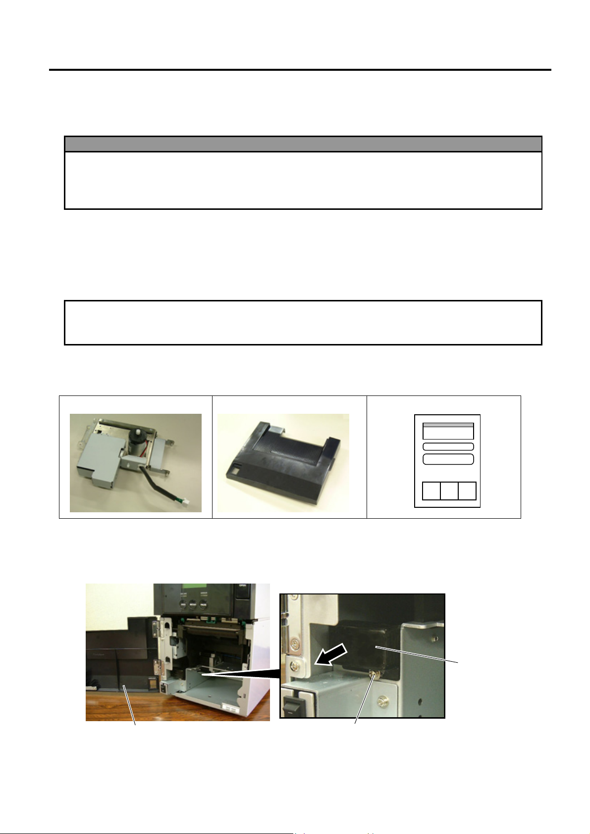
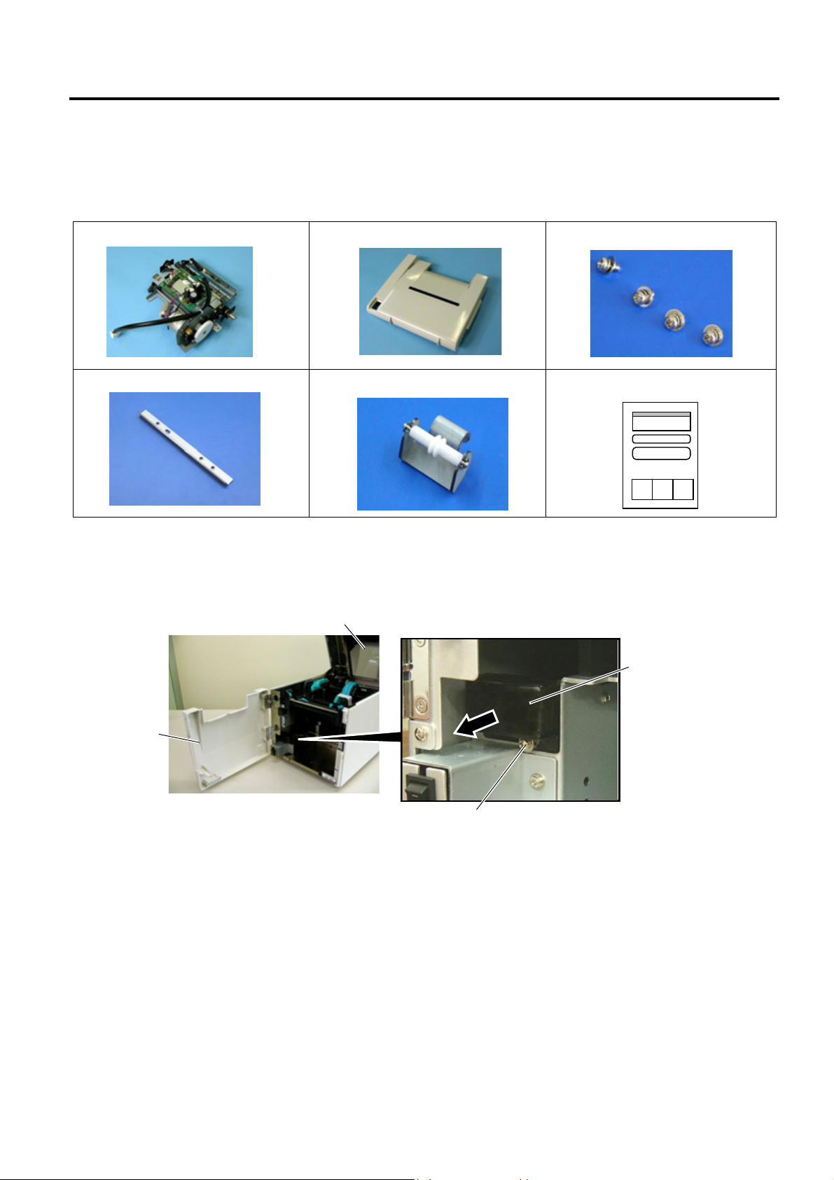
Packing List
The following parts are supplied with the kit. Make sure you have all items shown below.
Cutter Unit (1 pc.)
Cutter Module Cover (1 pc.)
Installation Manual (1 copy)
• Installation Procedure
1. Open the Front Cover, and remove the B-3x6 screw to detach the Connector Cover.
WARNING!
1. Turn the printer power off and disconnect the power cord before installing an optional
equipment.
2. Be careful not to pinch your fingers or hands with the covers.
3. Be careful not to injure your fingers when installing the cutter module.
CAUTION
!
Do not connect/disconnect the cutter harness to/from the printer within one minute from a power off
to
p
rotect the internal electrical circuit of the
p
rinter.
Front Cove
r
Connector Cover
B-3x6 Screw
INSTALLATION PROCEDURE FOR OPTIONAL EQUIPMENT EO15-33001A
1. Cutter Module
1- 2
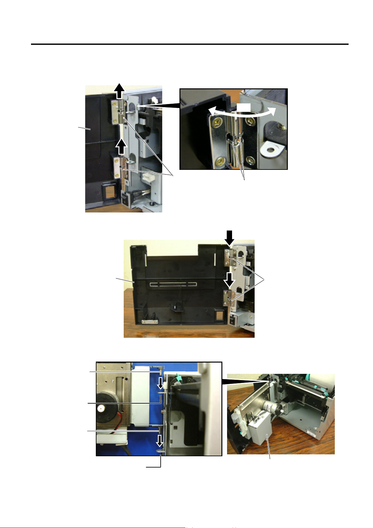
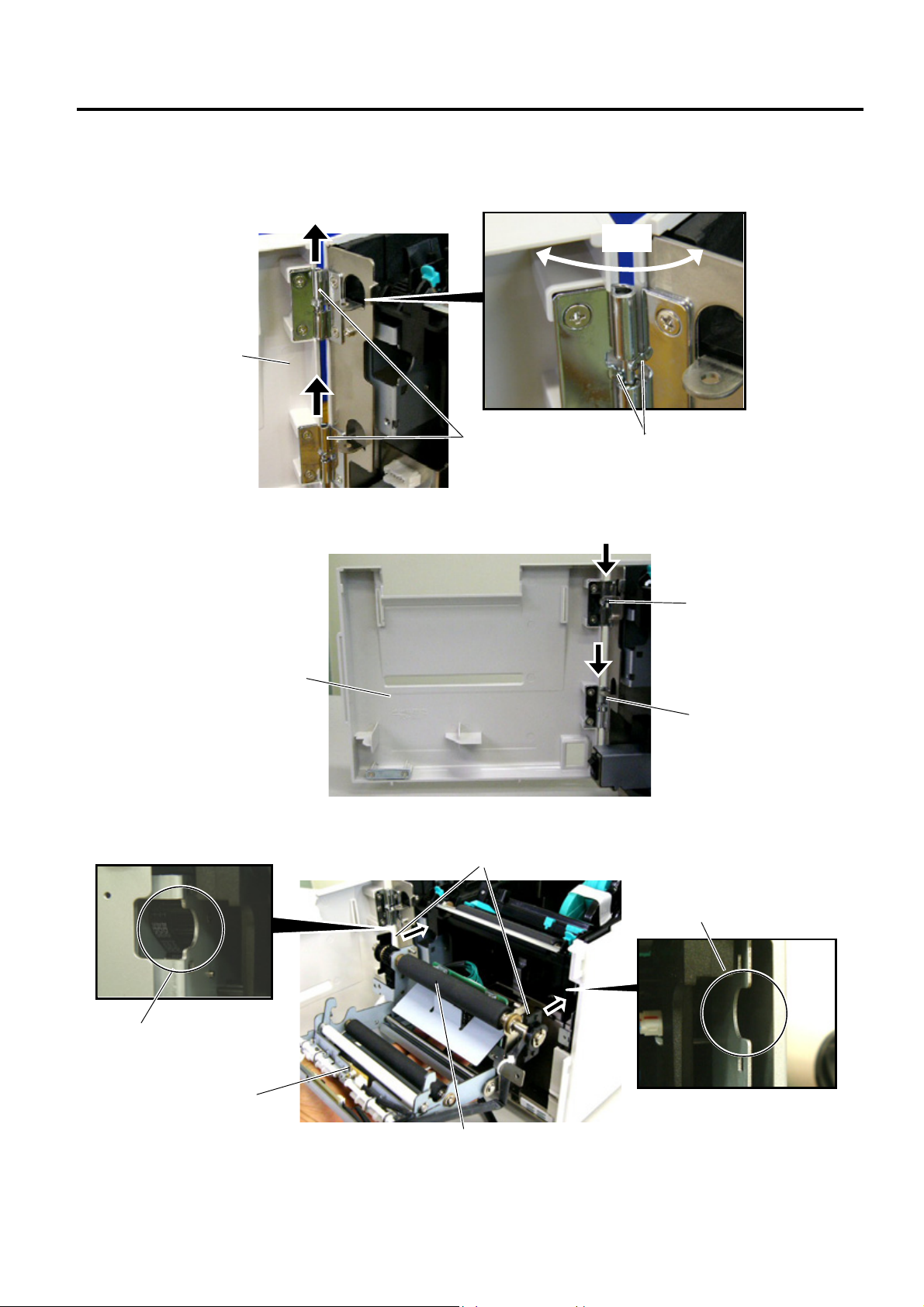
2. Open the Front Cover wider. Remove the Front Cove r by lifting it to disengage the hinge pins from the
hinge. The Front Cover cannot be removed unless it is opened at an angle of over 100 degrees a s the
stoppers of the hinge prevent disengagement.
3. Mount the Cutter Module Cover by inserting the hinge pins into the hinges.
4. Fit the Cutter Unit to the front of the printer by inserting the Hinge Pins into the Hinge Pin Holes.
Cutter Module Cove
r
Hinge
Hinge
Front Cove
r
Scre
w
100°
Cutter Unit
Hinge Pin Hole
Hinge Pin
Hinge Pin Hole
Hinge Pin
INSTALLATION PROCEDURE FOR OPTIONAL EQUIPMENT EO15-33001A
1. Cutter Module
1- 3
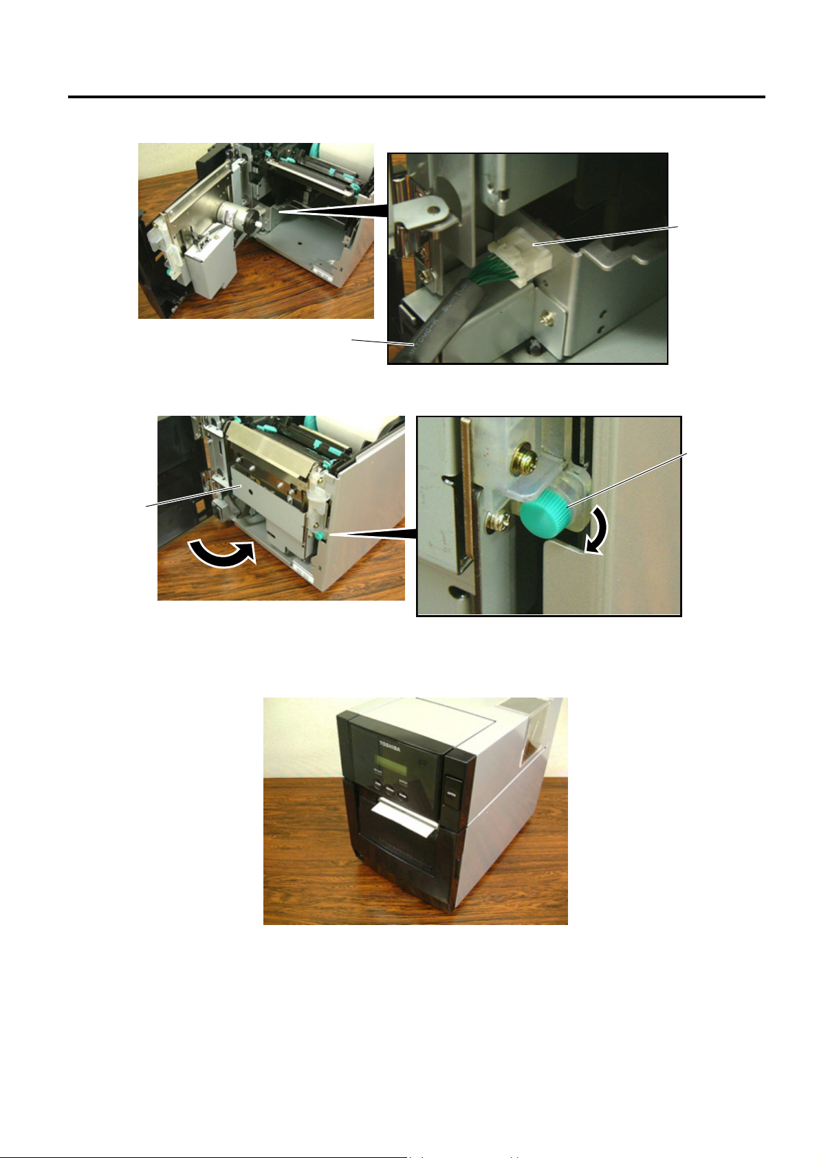
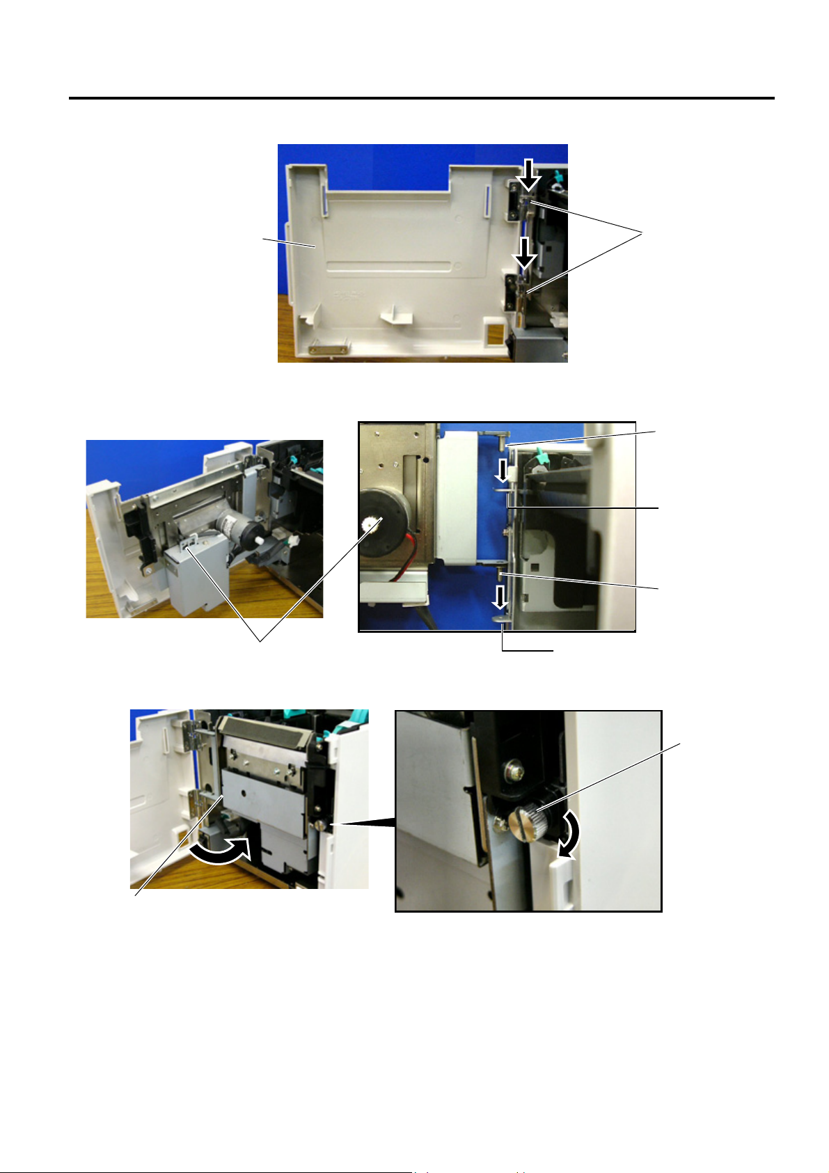
5. Connect the Cutter Harness to the connector at the front of the printer.
6. Close the Cutter Unit and secure it to the printer with the Set Screw.
7. Close the Cutter Module Cover.
• Media loading procedure------------- Owner’s Manual, Section 2.3
• Operation check------------------------ Owner’s Manual, Section 2.9
• System mode setting------------------System Mode Manual
• Cleaning --------------------------------- Owner’s Manual, Section 4.1.3
Cutter Harness
Connector
Cutter Unit
Set Screw
INSTALLATION PROCEDURE FOR OPTIONAL EQUIPMENT EO15-33001A
1. Cutter Module
1- 4
1.2 B-SA204P-QM-R
B-SA204P-QM-R is an optional cutter module for the B-SA4TP Series (Plastic cover).
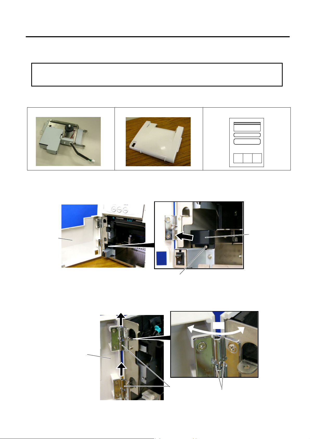
• Packing List
The following parts are supplied with the kit. Make sure you have all items shown below.
Cutter Unit (1 pc.)
Cutter Module Cover (1 pc.)
Installation Manual (1 copy)
• Installation Procedure
1. Open the Front Cover, and remove the Connector Cover.
2. Open the Front Cover wider. Remove the Front Cove r by lifting it to disengage the hinge pins from the
hinge. The Front Cover cannot be removed unless it is opened at an angle of over 100 degrees a s the
stoppers of the hinge prevent disengagement.
CAUTION
!
Do not connect/disconnect the cutter harness to/from the printer within one minute from a
p
ower of
f
to
p
rotect the internal electrical circuit of the
p
rinter.
Front Cove
r
Connector Cover
B-3x6 Scre
w
Front Cove
r
Hinge
100°
Stopper
INSTALLATION PROCEDURE FOR OPTIONAL EQUIPMENT EO15-33001A
1. Cutter Module
1- 5
3. Mount the Cutter Module Cover by inserting the hinge pins into the hinges.
4. Fit the Cutter Unit to the front of the printer by inserting the Hinge Pins into the Hinge Pin Holes.
5. Close the Cutter Unit and secure it to the printer with the Set Screw.
Cutter Module Cove
r
Hinge
Cutter Unit
Hinge Pin
Hinge Pin
Hinge Pin Hole
Hinge Pin Hole
Cutter Unit
Set Screw
INSTALLATION PROCEDURE FOR OPTIONAL EQUIPMENT EO15-33001A
1. Cutter Module
1- 6
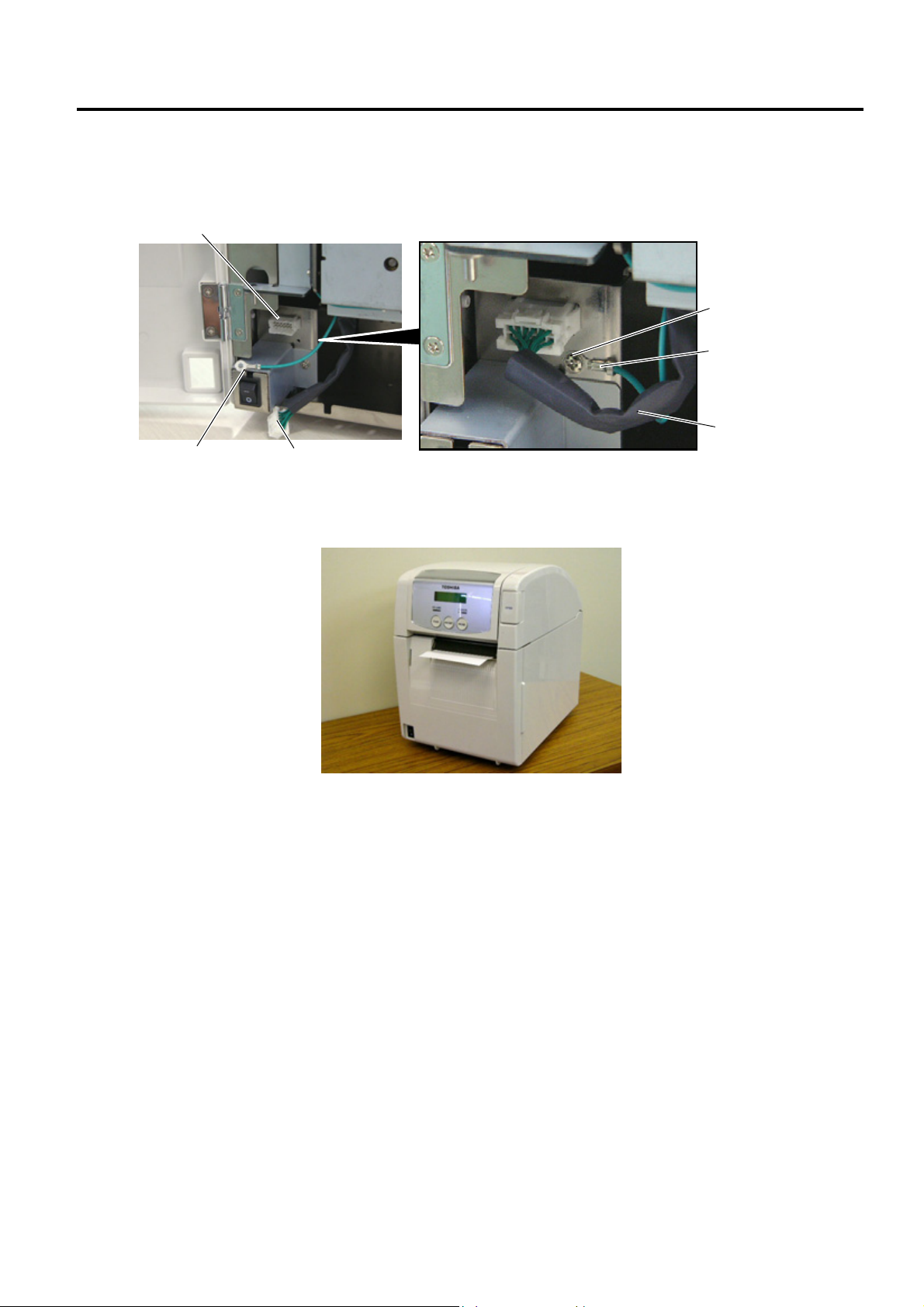
6. Secure the ground wire of the cutter unit to the printer with the B-3x6 screw removed in Step 1, as shown
in the picture.
7. Connect the cutter harness to the connector at the front of the printer.
8. Close the Cutter Module Cover. After that, perform an operation check for a proper cut issue.
• Media loading procedure------------- Owner’s Manual, Section 2.3
• Operation check------------------------ Owner’s Manual, Section 2.9
• System mode setting------------------System Mode Manual
• Cleaning --------------------------------- Owner’s Manual, Section 4.1.3
Cutter Harness
Ground Wire
B-3x6 Screw
Ground Wire
Cutter Harness
Connecto
r
INSTALLATION PROCEDURE FOR OPTIONAL EQUIPMENT EO15-33001A
(Revision Date: Jan. 19, 2006)
2. Strip Module
2- 1
2. Strip Module
NOTE: Make sure that the firmware version is V1.1 or greater. Firmware V1.0 does not support the strip module.
2.1 B-SA904-H-QM-R
B-SA904-H-QM-R is an optional strip module for the B-SA4TM Series (Metal cover).
• Packing List
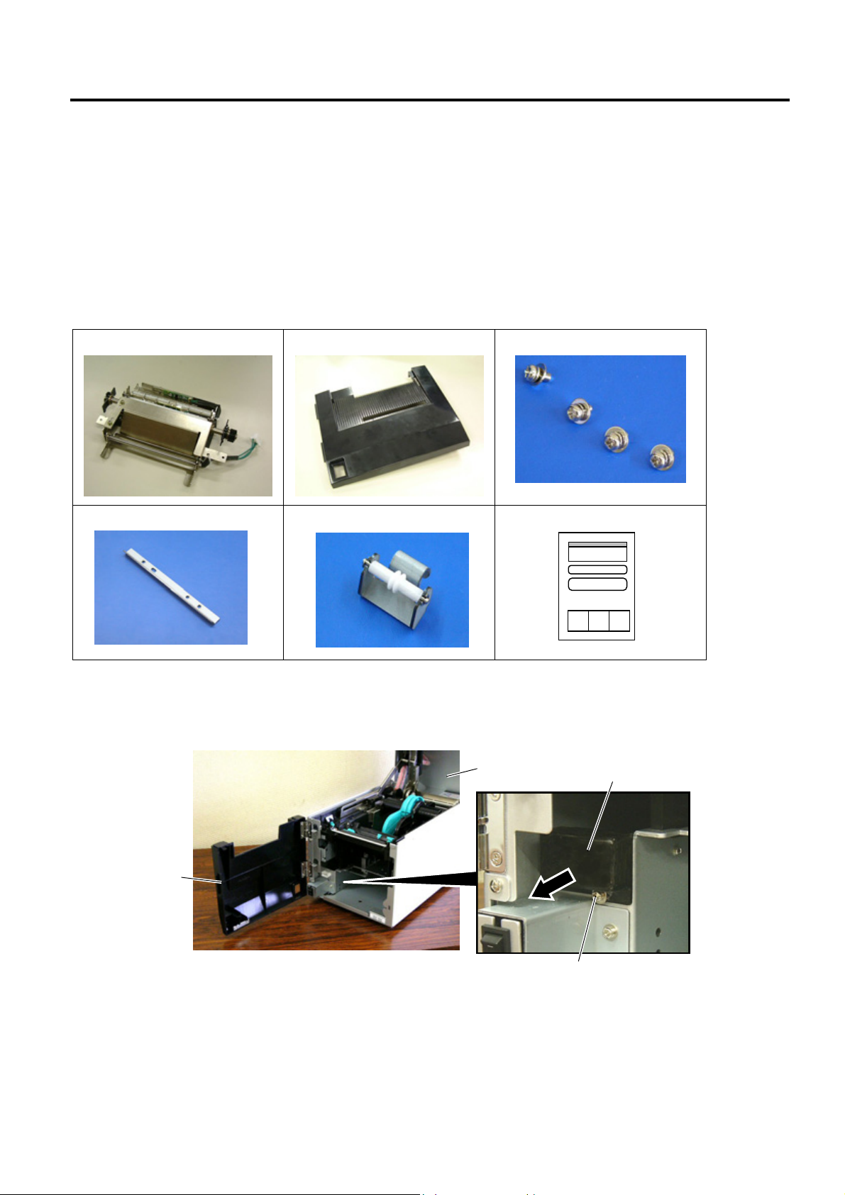
The following parts are supplied with the kit. Make sure you have all items shown below.
Strip Unit (1 pc.)
Strip Module Cover (1 pc.)
SMW-3x6 Screw (4 pc.)
Cutter (1 pc.)
Guide Roller (1 pc.)
Installation Manual (1 copy)
NOTE: When issuing labels in batch mode even though the strip module is fitted, please use the provided cutter
to tear off the issued labels. Do not attach the cutter when labels are stripped one by one.
• Installation Procedure
1. Open the Top Cover and the Front Cover. Remove the B-3x6 screw to detach the Connector Cover.
Front Cove
r
Top Cover
Connector Cover
B-3x6 Scre
w
INSTALLATION PROCEDURE FOR OPTIONAL EQUIPMENT EO15-33001A
2. Strip Module
2- 2
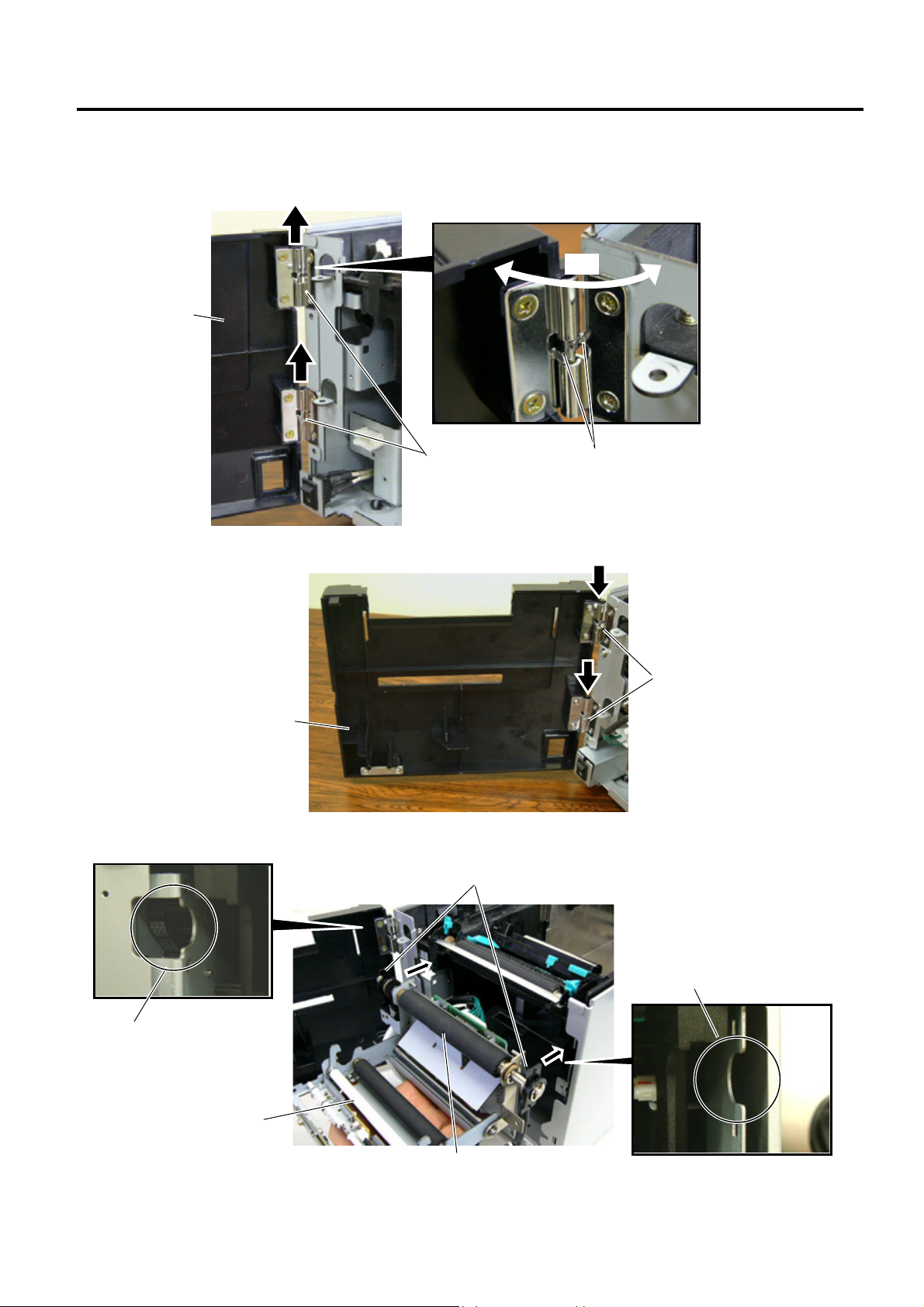
2. Open the Front Cover wider. Remove the Front Cove r by lifting it to disengage the hinge pins from the
hinge. The Front Cover cannot be removed unless it is opened at an angle of over 100 degrees a s the
stoppers of the hinge prevent disengagement.
3. Mount the Strip Module Cover by inserting the hinge pins into the hinges.
4. Fit the Shaft Holders of the Backing Paper Feed Roller into the cuts of the printer.
Hinge
Strip Module Cove
r
Shaft Holder
Strip Unit
Cut
Cut
Backing Paper Feed Roller
Hinge
Front Cove
r
Scre
w
100°
INSTALLATION PROCEDURE FOR OPTIONAL EQUIPMENT EO15-33001A
2. Strip Module
2- 3
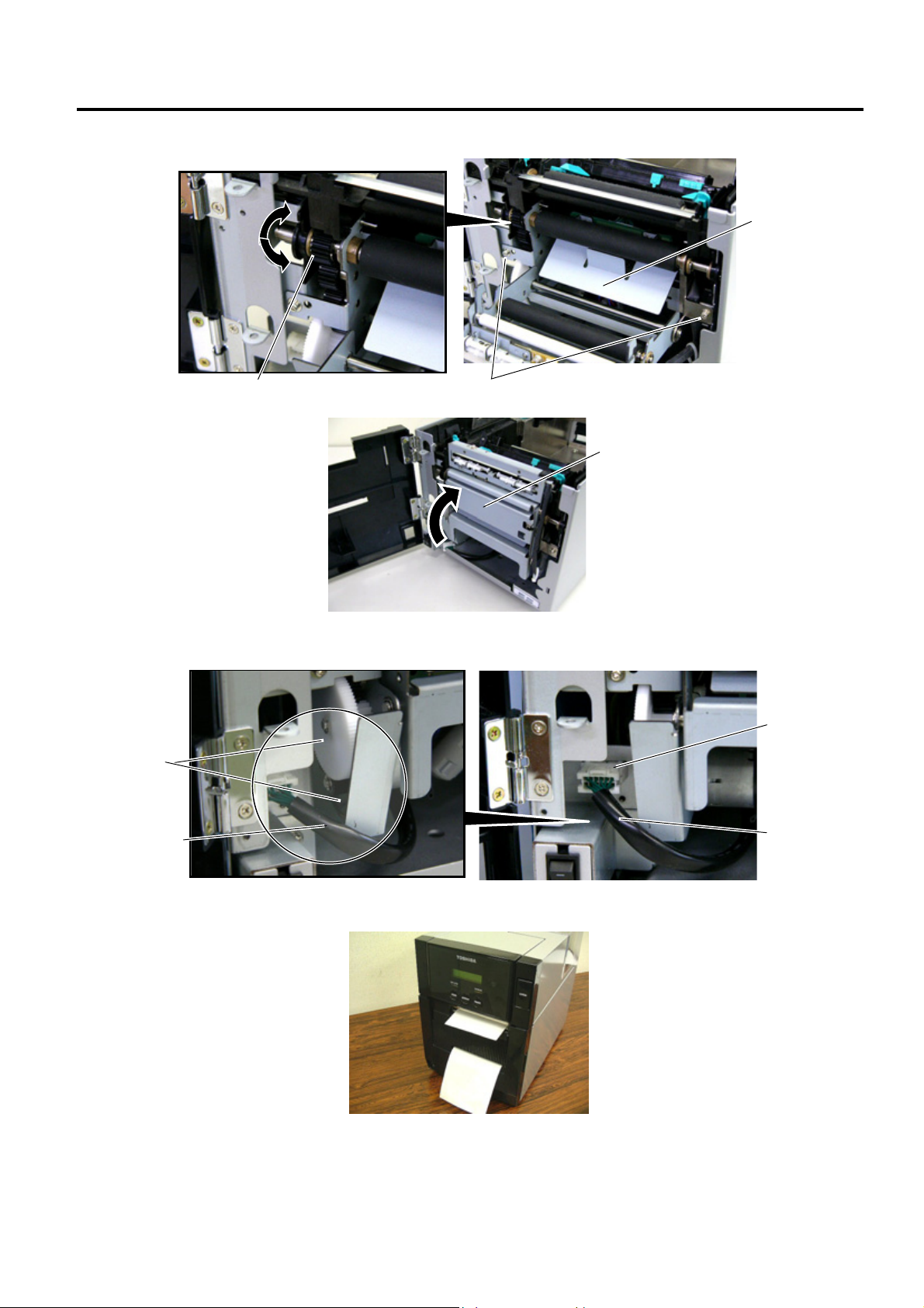
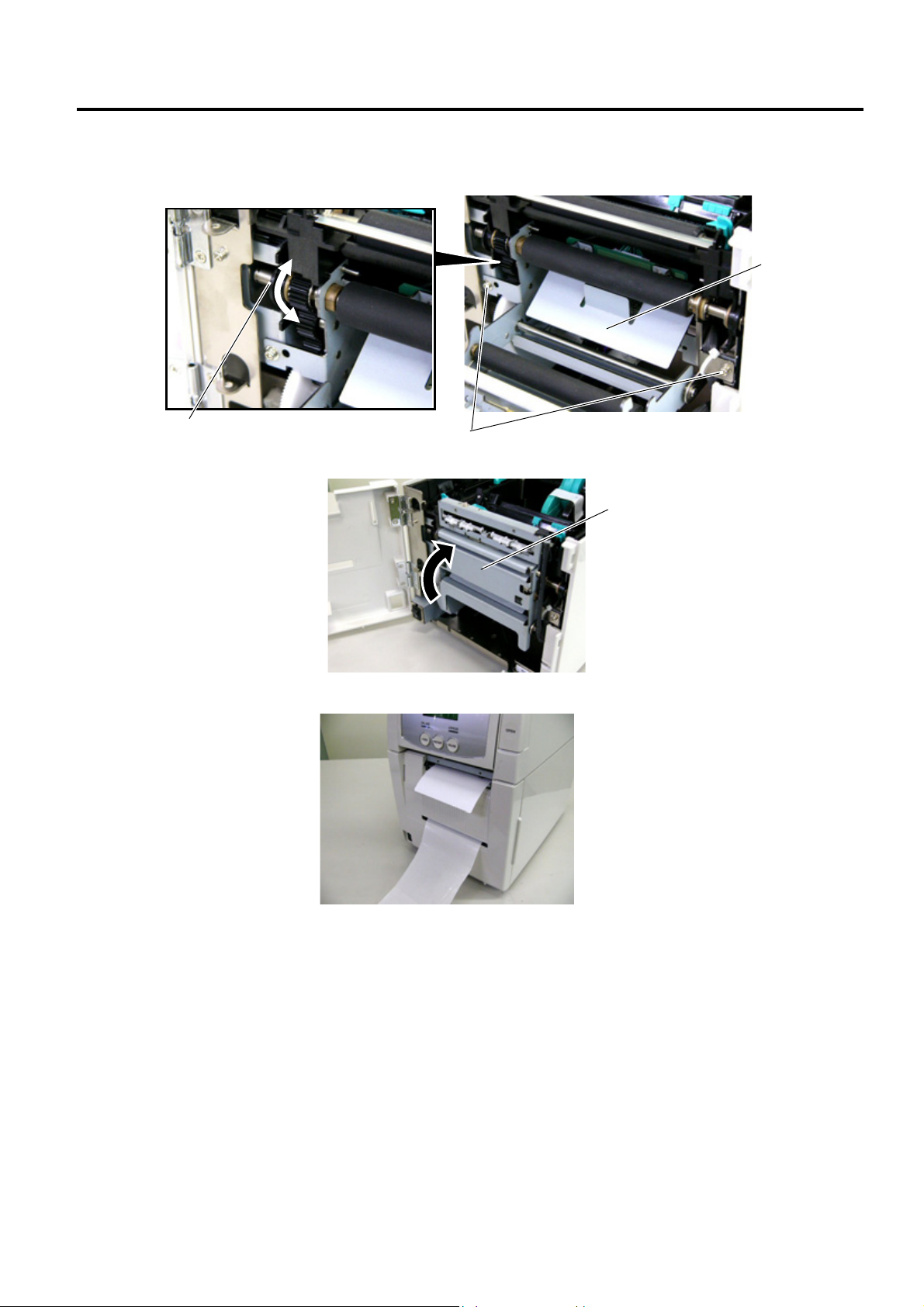
5. Secure the Strip Unit to the printer with the two screws. Make sure that the Feed Roller Gear rotates
smoothly.
6. Close the Strip Unit.
7. Connect the Strip Harness to the connector at the front of the printer. At this time, carefully avoid contact
of the strip harness with the gears.
8. Close the Strip Module Cover.
Perform an operation check for a proper strip issue.
• Media loading procedure------------- Owner’s Manual, Section 2.3
• Operation check------------------------ Owner’s Manual, Section 2.9
• System mode setting------------------System Mode Manual
• Cleaning --------------------------------- Owner’s Manual, Section 4.1.4
SMW-3x6 Screw
Feed Roller Gear
Strip Unit
Strip Unit
Connector
Strip Harness
Strip Harness
Gea
r
INSTALLATION PROCEDURE FOR OPTIONAL EQUIPMENT EO15-33001A
(Revision Date: Jan. 19, 2006)
2. Strip Module
2- 4
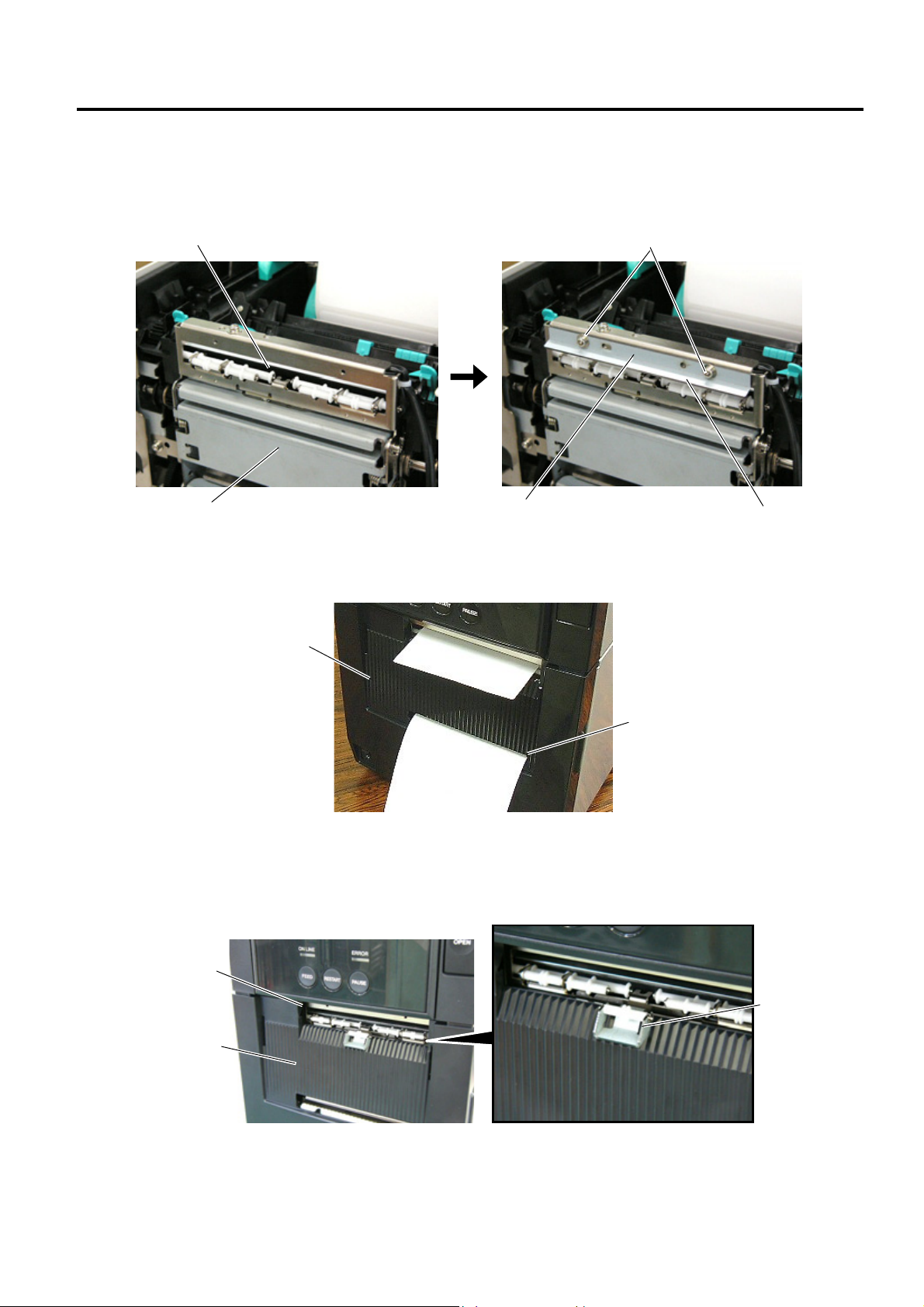
• Attaching the Cutter
The enclosed cutter is used to tear off the batch-issued labels. Attach the cutter with the two SMW-3x6
screws as shown in the picture below. Insert the leading edge of the labels into the opening under the
cutter.
NOTE: Depending on the backing paper types, tearing off the backing paper against the slot of the strip module
cover may cause it to wind onto the inner rollers. It is advisable to tear off or cut the backing paper
outside the strip module cover.
• How to use the Guide Roller
When issuing the label with the length of 50 mm or more, fit the guide roller to the center of the strip module
cover to prevent the stripped label from sticking to the cover.
Strip Unit
SMW-3x6 Screw
Cutte
r
Opening
Edge
Slot
Strip Module Cove
r
Strip Module Cove
r
Guide Roller
Opening
INSTALLATION PROCEDURE FOR OPTIONAL EQUIPMENT EO15-33001A
(Revision Date: Jan. 19, 2006)
2. Strip Module
2- 5
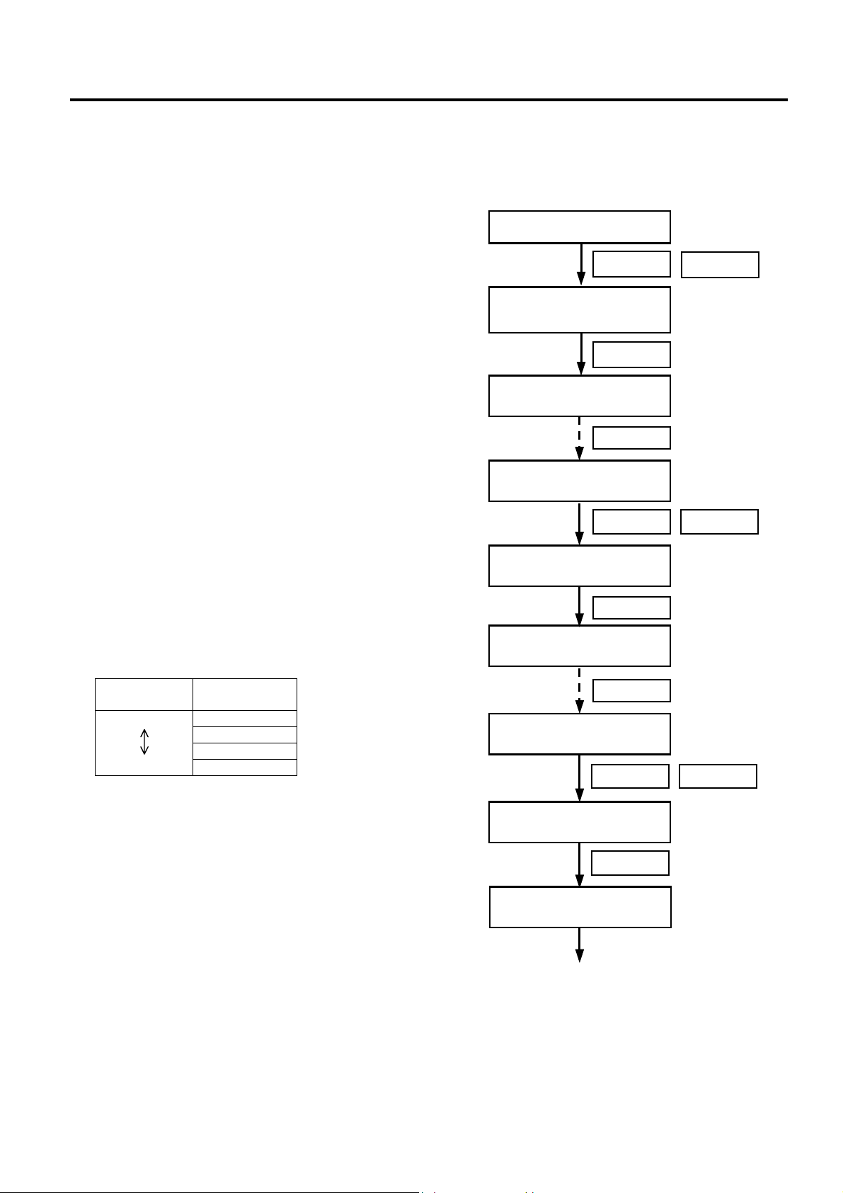
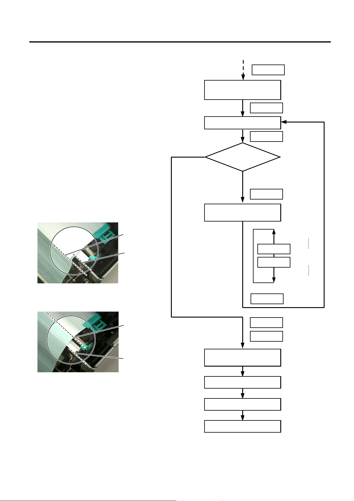
• System Mode Settings for Stripping PET Labels
When using PET labels on the strip module, please set the following system mode parameters in advance.
1. Connect the printer to a PC.
2. Load a PET label stock on the printer.
3. Turn ON the printer while holding down the
[FEED] key and [PAUSE] key.
4. When “<1>DIAG. “ is displayed on the LCD,
press the [FEED] key to choose
<2>PARAMETER SET” menu.
5. Press the [PAUSE] key repeatedly until
“PRE PEEL OFF” appears on the LCD.
6. As the default is OFF, choose “PRE PEEL
OFF ON” with the [FEED] or [RESTART]
key. Then, press the [PAUSE] key.
7. “P.P. FEED +0.0mm” is displayed on the
LCD.
Press the [PAUSE] key repeatedly until
“PEEL OFF TRQ” appears on the LCD.
8. This menu is to set the strip motor torque.
As the default is R0, choose R3 with the
[FEED] or [RESTART] key. Then, press
the [PAUSE] key.
NOTE: Setting the motor torque higher
makes the strip issue easier.
Strip motor
torque
Value
R0
R1
R2
Low
High
R3
RESTARTFEED
<2>PARAMETER SET
PRE PEEL OFF ON
<2>PARAMETER SET
P.P.FEED +0.0mm
<1>DIAG.
V1.1
Turn the power ON.
FEED
PAUSE
FEED
PAUSE
<2>PARAMETER SET
<2>PARAMETER SET
PRE PEEL OFF OFF
PAUSE
<2>PARAMETER SET
PEEL OFF TRQ R0
RESTARTFEED
<2>PARAMETER SET
PEEL OFF TRQ R3
PAUSE
<2>PARAMETER SET
PAUSE
(Continued.)
INSTALLATION PROCEDURE FOR OPTIONAL EQUIPMENT EO15-33001A
(Revision Date: Jan. 19, 2006)
2. Strip Module
2- 6
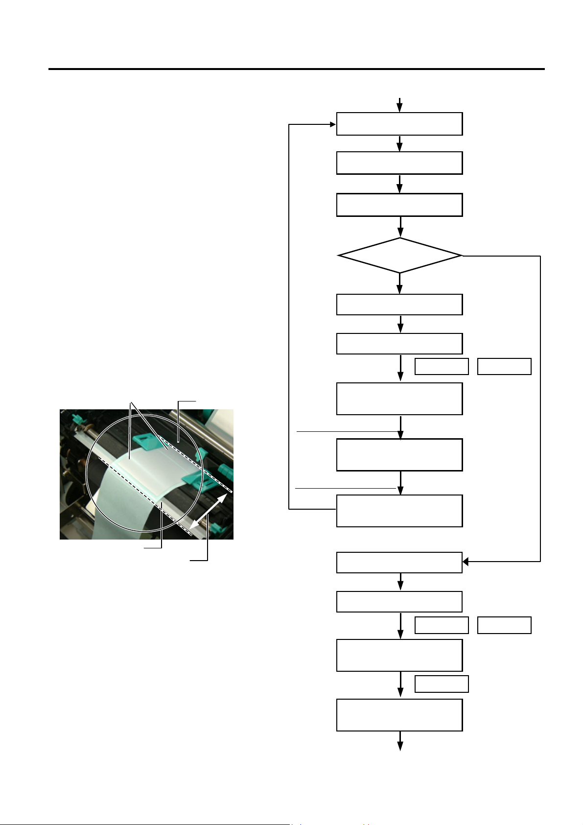
9. Turn off the printer, and then back to on.
Send an issue command to the printer for
strip issue.
10. If necessary, fine adjust the print start
position and strip position in the system
mode.
NOTES:
1. It is recommended that the print start
position and strip position are adjusted on
the actual print condition.
2. When short-pitch labels are used, the print
start position may misalign on the first few
labels. In that case, feed the labels
between the media sensor and the strip
shaft, and discard them.
11. Repeat Steps 9 and 10 for position fine
adjustment.
12. After the print position and strip position
are properly adjusted, access
“<2>PARAMETER SET” menu in the
system mode again.
Turn the power OFF.
Issue labels.
(Continued.)
<3>ADJUST SET
FEED ADJ. +0.0mm
<3>ADJUST SET
CUT ADJ. +0.0mm
Print position fine adjustment
Strip position fine adjustment
Power OFF
Power ON
FEED RESTART
<1>DIAG.
V1.1
Turn the power ON.
Print position
Adjustment
is re
q
uired.
Good
Turn the power OFF.
Turn the power ON.
FEED RESTART
<1>DIAG.
V1.1
FEED
<2>PARAMETER SET
Continued.
Strip Shaft
Media Senso
r
Discard labels between the
media sensor and the strip shaft.
Label
INSTALLATION PROCEDURE FOR OPTIONAL EQUIPMENT EO15-33001A
(Revision Date: Jan. 19, 2006)
2. Strip Module
2- 7
13. Press the [PAUSE] key repeatedly until
“P.P.FEED” appears on the LCD.
14. Press the [FEED] key to feed a label for
checking the next label’s stop position. If
the next label stops with its top edge
aligning with the strip shaft edge, an
adjustment is not required. Go to Step 15.
If not, press the [RESTART] key to return
to “P.P.FEED +0.0mm” display, and
adjust the pre-strip amount. Set the value
in a range from +9.9 to −2.5 with the
[FEED] or [RESTART] key.
When the top edge of the label stops past
the strip shaft edge, set a negative (−)
value.
When the top edge of the label stops short
of the strip shaft edge, set a positive (+)
value.
15. When the adjustment is completed, press
the [PAUSE] key twice to finish the setting.
16. Send an issue command to the printer
and check for proper strip issue.
Top edge of
the label
Strip Shaft Edge
Top edge of
the label
Strip Shaft Edge
Continued.
PAUSE
<2>PARAMETER SET
P.P.FEED +0.0mm
PAUSE
A label is fed.
+9.9mm
+9.8mm
:
:
+0.1mm
+0.0mm
-0.1mm
:
:
-2.4mm
-2.5mm
RESTART
FEED
PAUSE
<2>PARAMETER SET
P.P.FEED +0.0mm
Check the next
label’s stop
p
osition
The next label stops with its
top edge aligning with the
strip shaft edge.
The next label stops with its
top edge misaligning with the
strip shaft edge.
RESTART
PAUSE
PAUSE
<2>PARAMETER SET
BACK SPEED STD
Turn the powe
r
OFF.
Turn the power ON.
Label issue
FEED
INSTALLATION PROCEDURE FOR OPTIONAL EQUIPMENT EO15-33001A
(Revision Date: Jan: 19, 2006)
2. Strip Module
2- 8
2.2 B-SA904P-H-QM-R
B-SA904P-H-QM-R is an optional strip module for the B-SA4TP Series (Plastic cover).
• Packing List
Strip Unit (1 pc.)
Strip Module Cover (1 pc.)
SMW-3x6 Screw (4 pcs.)
Cutter (1 pc.)
Guide Roller (1 pc.)
Installation Manual (1 copy)
NOTE: When issuing labels in batch mode even though the strip module is fitted, please use the provided
cutter to tear off the issued labels. Do not attach the cutter when labels are stripped one by one.
• Installation Procedure
1. Open the Top Cover and the Front Cover. Remove the Connector Cover.
Front Cove
r
Connector Cover
Top Cove
r
B-3x6 Scre
w
INSTALLATION PROCEDURE FOR OPTIONAL EQUIPMENT EO15-33001A
2. Strip Module
2- 9
2. Open the Front Cover wider. Remove the Front Cover by lifting it to disengage the hi nge pins from the
hinge. The Front Cover cannot be removed unless it is opened at an angle of over 100 deg rees as the
stoppers of the hinge prevent disengagement.
3. Mount the strip Module Cover by inserting the hinge pins into the hinges.
4. Fit the Shaft Holders of the Backing Paper Feed Roller into the cuts of the printer.
Front Cove
r
Hinge
100°
Stopper
Hinge
Hinge
Strip Module Cove
r
Shaft Holder
Strip Uni
t
Cut
Cut
Backing Paper Feed Roller
INSTALLATION PROCEDURE FOR OPTIONAL EQUIPMENT EO15-33001A
2. Strip Module
2- 10
5. Secure the Strip Unit to the printer with the two screws. Make sure that the Feed Roller Gear rotates
smoothly.
6. Close the Strip Unit.
7. Close the Strip Module Cover. Perform an operation check for a proper strip issue.
• Media loading procedure------------- Owner’s Manual, Section 2.3
• Operation check------------------------ Owner’s Manual, Section 2.9
• System mode setting------------------System Mode Manual
• Cleaning --------------------------------- Owner’s Manual, Section 4.1.4
Strip Unit
SMW-3x6 Screw
Strip Unit
Feed Roller Gear
Loading...