


 Loading...
TEC Thermal Printer
B-480-QP SERIES
Owner’s Manual Mode d’emploi Bedienungsanleitung
Manual de instrucciones Gebruikershandleiding Manuale Utente

LIST OF STANDARDS OF CONFORMITY
Manufacturer |
: |
TOSHIBA TEC Corporation |
Address |
: 570 Ohito, Ohito-Cho, Tagata-Gun, Shizuoka-Ken, 410-2323 |
|
|
|
Japan |
|
|
declares that following product |
Product Name |
: |
Bar Code Printer |
Model |
: B-48X-YY |
|
Options |
: |
All |
|
|
conforms to the following product specifications |
Safety |
: |
EN 60 950 |
EMC |
: EN 55 022 |
|
|
|
EN 50082-1 |
Harmonics |
: |
EN 60 555-2 |
Voltage Fluctuations |
: |
EN 60 555-3 |
Supplementary Information
The product herewith complies with the requirements of the Low Voltage Directive 73/23/ EEC, and the EMC directive 89/336/EEC.
1)The product was tested in a typical set up TOSHIBA TEC personnel advocated.
2)The following technical documentation has been filed for review.
•Factory Inspection Certificate by TÜV
•Owner's Manual
•Schematic
•Certificates and Test Reports
Copyright © 1999
by TOSHIBA TEC CORPORATION All Rights Reserved
570 Ohito, Ohito-cho, Tagata-gun, Shizuoka-ken, JAPAN

TEC Thermal Printer
B-480-QP SERIES
Owner’s Manual
Safety Summary
ENGLISH VERSION EO1-33007
Safety Summary
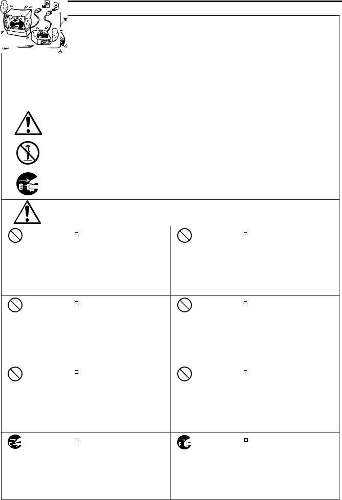
Personal safety in handling or maintaining the equipment is extremely important. Warnings and Cautions necessary for safe handling are included in this manual. All warnings and cautions contained in this manual should be read and understood before handling or maintaining the equipment.
Do not attempt to effect repairs or modifications to this equipment. If a fault occurs that cannot be rectified using the procedures described in this manual, turn off the power, unplug the machine, then contact your authorized TOSHIBA TEC representative for assistance.
Meanings of Each Symbol
This symbol indicates warning items (including cautions). Specific warning contents are drawn inside the  symbol. (The symbol on the left indicates a general caution.)
This symbol indicates prohibited actions (prohibited items). Specific prohibited contents are drawn inside or near the symbol. (The symbol on the left indicates “no disassembling”.)
This symbol indicates actions which must be performed. Specific instructions are drawn inside or near the symbol.
(The symbol on the left indicates “disconnect the power cord plug from the outlet”.)
|
|
This indicates that there is the risk of death or serious injury if the |
||||
WARNING machines are improperly handled contrary to this indication. |
||||||
Any other than the |
|
Do not use voltages other than the |
Prohibited |
|
Do not plug in or unplug the power |
|
specified AC voltage |
|
|
||||
voltage (AC) specified on the rating |
cord plug with wet hands as this may |
|||||
is prohibited. |
|
|||||
|
plate, as this may cause fire or |
|
cause electric shock. |
|||
|
electric shock. |
|
|
|
||
Prohibited |
|
If the machines share the same |
Prohibited |
|
|
Do not place metal objects or |
|
|
|
||||||
|
|
||||||
outlet with any other electrical |
water-filled containers such as flower |
||||||
|
|
||||||
|
appliances which consume large |
|
vases, flower pots or mugs, etc. on |
||||
|
amounts of power, the voltage will |
|
top of the machines. If metal objects |
||||
|
fluctuate widely each time these |
|
or spilled liquid enter the machines, |
||||
|
appliances operate. Be sure to |
|
this may cause fire or electric |
||||
|
provide an exclusive outlet for the |
|
shock. |
||||
|
machine as this may cause the |
|
|
|
|
||
|
machines to malfunction. |
|
|
|
|
||
|
|
|
|
|
|
|
|
Prohibited |
|
Do not insert or drop metal, |
Prohibited |
|
|
Do not scratch, damage or modify |
|
|
|
|
|||||
|
|
|
|||||
flammable or other foreign objects into |
the power cords. Also, do not place |
||||||
|
|
||||||
|
the machines through the ventilation |
|
heavy objects on, pull on, or exces- |
||||
|
slits, as this may cause fire or electric |
|
sively bend the cords, as this may |
||||
|
shock. |
|
cause fire or electrical shock. |
||||
Disconnect |
|
If the machines are dropped or their |
Disconnect |
|
Continued use of the machines in an |
|
|
||||
|
|
||||
the plug. |
cabinets damaged, first turn off the |
the plug. |
abnormal condition such as when the |
||
|
power switches and disconnect the |
|
machines are producing smoke or |
||
|
power cord plugs from the outlet, and |
|
strange smells may cause fire or elec- |
||
|
then contact your authorized |
|
tric shock. In these cases, immedi- |
||
|
|
ately turn off the power switches and |
|||
|
TOSHIBA TEC representative for |
|
|||
|
|
disconnect the power cord plugs from |
|||
|
assistance. Continued use of the |
|
|||
|
|
the outlet. Then, contact your author- |
|||
|
machine in that condition may cause |
|
|||
|
|
ized TOSHIBA TEC representative for |
|||
|
fire or electric shock. |
|
|||
|
|
assistance. |
|||
|
|
|
|
||
(i)

Safety Summary
ENGLISH VERSION EO1-33007
|
|
Disconnect |
|
If foreign objects (metal fragments, |
Disconnect |
|
|
When unplugging the power cords, |
|
|
|
|
|
||||
|
|
|
|
|
||||
|
|
the plug. |
water, liquids) enter the machines, |
the plug. |
be sure to hold and pull on the plug |
|||
|
|
|
first turn off the power switches and |
|
portion. Pulling on the cord portion |
|||
|
|
|
disconnect the power cord plugs from |
|
may cut or expose the internal wires |
|||
|
|
|
the outlet, and then contact your |
|
and cause fire or electric shock. |
|||
|
|
|
authorized TOSHIBA TEC repre- |
|
|
|
|
|
|
|
|
sentative for assistance. Continued |
|
|
|
|
|
|
|
|
use of the machine in that condition |
|
|
|
|
|
|
|
|
may cause fire or electric shock. |
|
|
|
|
|
|
|
|
|
|
|
|
|
|
|
|
Connect a |
|
Ensure that the equipment is |
No disassem- |
|
|
Do not remove covers, repair or |
|
|
grounding |
|
|
|
|||
|
|
properly grounded. Extension cables |
bling. |
modify the machine by yourself. You |
||||
|
|
wire. |
||||||
|
|
|||||||
|
|
should also be grounded. Fire or |
|
may be injured by high voltage, very |
||||
|
|
|
|
|||||
|
|
|
|
hot parts or sharp edges inside the |
||||
|
|
|
electric shock could occur on |
|
||||
|
|
|
|
machine. |
||||
|
|
|
improperly grounded equipment. |
|
||||
|
|
|
|
|
|
|
||
|
|
|
|
|
|
|
|
|
 CAUTIONThis indicates that there is the risk of personal Injury or damage to objects if the machines are improperly handled contrary to this indication.
Precautions
The following precautions will help to ensure that this machine will continue to function correctly.
•Try to avoid locations that have the following adverse conditions:
* |
Temperatures out of the specification |
* |
Direct sunlight |
* |
High humidity |
* |
Shared power source |
* |
Excessive vibration |
* |
Dust/Gas |
•The cover should be cleaned by wiping with a dry cloth or a cloth slightly dampened with a mild detergent solution. NEVER USE THINNER OR ANY OTHER VOLATILE SOLVENT on the plastic covers.
•USE ONLY TOSHIBA TEC SPECIFIED paper and ribbons.
•DO NOT STORE the paper or ribbons where they might be exposed to direct sunlight, high temperatures, high humidity, dust, or gas.
•Ensure the printer is operated on a level surface.
•Any data stored in the memory of the printer could be lost during a printer fault.
•Try to avoid using this equipment on the same power supply as high voltage equipment or equipment likely to cause mains interference.
•Unplug the machine whenever you are working inside it or cleaning it.
•Keep your work environment static free.
•Do not place heavy objects on top of the machines, as these items may become unbalanced and fall causing injury.
•Do not block the ventilation slits of the machines, as this will cause heat to build up inside the machines and may cause fire.
•Do not lean against the machine. It may fall on you and could cause injury.
•Care must be taken not to injure yourself with the printer paper cutter.
•Unplug the machine when it is not used for a long period of time.
Request Regarding Maintenance
•Utilize our maintenance services.
After purchasing the machine, contact your authorized TOSHIBA TEC representative for assistance once a year to have the inside of the machine cleaned. Otherwise, dust will build up inside the machines and may cause a fire or a malfunction. Cleaning is particularly effective before humid rainy seasons.
•Our preventive maintenance service performs the periodic checks and other work required to maintain the quality and performance of the machines, preventing accidents beforehand. For details, please consult your authorized TOSHIBA TEC representative for assistance.
•Using insecticides and other chemicals
Do not expose the machines to insecticides or other volatile solvents. This will cause the cabinet or other parts to deteriorate or cause the paint to peel.
(ii)

|
|
|
ENGLISH VERSION EO1-33007 |
|
|
TABLE OF CONTENTS |
|
|
|
|
Page |
1. |
INTRODUCTION ............................................................................ |
E1-1 |
|
|
1.1 |
Applicable Model ................................................................................... |
E1- 2 |
|
1.2 |
Accessories ........................................................................................... |
E1- 2 |
2. |
SPECIFICATIONS ......................................................................... |
E2-1 |
|
|
2.1 |
Printer .................................................................................................... |
E2- 1 |
|
2.2 |
Options .................................................................................................. |
E2- 2 |
|
2.3 |
Ribbon ................................................................................................... |
E2- 2 |
|
2.4 |
Media ..................................................................................................... |
E2- 3 |
3. |
OVERVIEW .................................................................................... |
E3-1 |
|
|
3.1 |
Front/Rear View..................................................................................... |
E3- 1 |
|
3.2 |
Operation Panel .................................................................................... |
E3- 1 |
4. |
INSTALLING THE PRINTER ......................................................... |
E4-1 |
|
|
4.1 |
Connecting the Power Cord and Cables ............................................... |
E4- 1 |
|
4.2 |
Procedure for Fitting Fan Filter .............................................................. |
E4- 1 |
5. |
LOADING THE MEDIA .................................................................. |
E5-1 |
|
6. |
LOADING THE RIBBON ............................................................... |
E6-1 |
|
7. |
INSERTING THE OPTIONAL PCMCIA CARD.............................. |
E7-1 |
|
8. |
CARE/HANDLING OF THE MEDIA AND RIBBON ....................... |
E8-1 |
|
9. |
GENERAL MAINTENANCE .......................................................... |
E9-1 |
|
|
9.1 |
Cleaning ................................................................................................ |
E9- 1 |
|
9.2 |
Covers and Panels ................................................................................ |
E9- 2 |
|
9.3 |
Removing Jammed Paper ..................................................................... |
E9- 2 |
|
9.4 |
Threshold Setting .................................................................................. |
E9- 4 |
10. |
TROUBLESHOOTING ................................................................. |
E10-1 |
|
CAUTION:
1.This manual may not be copied in whole or in part without prior written permission of TOSHIBA TEC.
2.The contents of this manual may be changed without notification.
3.Please refer to your local Authorized Service representative with regard to any queries you may have in this manual.

1. INTRODUCTION
ENGLISH VERSION EO1-33007
1. INTRODUCTION
1. INTRODUCTION
Thank you for choosing the TEC B-480 series thermal/transfer printer. This high performance printer is equipped with superior hardware including the specially developed (12 dots/mm, 304.8 dots/inch) near edge print head which will allow very clear print at a maximum speed of 203.2 mm/sec. (8 inches/sec.). The media supply is internal. Optional features include an automatic ribbon saver, a built-in rewinder/strip mechanism and external media supply.
This manual contains general set-up and maintenance information and should be read carefully to help gain maximum performance and life from your printer. For most queries please refer to this manual and keep it safe for future reference.
WARNING
This is a Class A product. In a domestic environment this product may cause radio interference in which case the user may be required to take adequate measures.
CAUTION
To avoid injury, be careful not to catch or jam your fingers while opening or closing the cover.
CAUTION
Do not touch moving parts. To reduce the risk that fingers, jewelry, clothing, etc., be drawn into the moving parts, push the switch in the "OFF" position to stop movement.
E1-1
1. INTRODUCTION
ENGLISH VERSION EO1-33007
1.1 Applicable Model
1.1Applicable Model
•B-482-TS10-QP Model name description
B - 4 8 2 - T S 1 0 - Q P
QP: European version
Issue mode
S: Batch
Resolution
T:12 dots/mm
2:Thermal direct/Thermal transfer
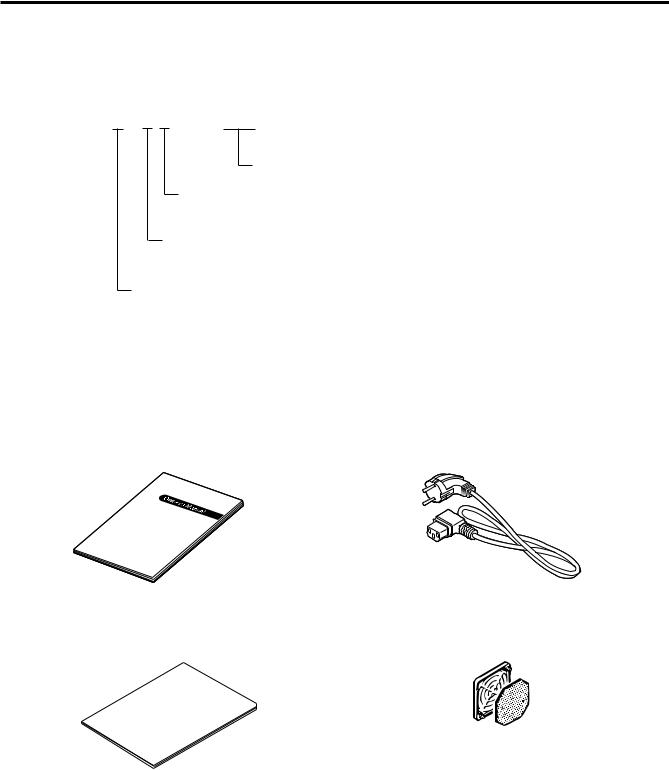
1.2Accessories
Owner's Manual |
Power Cord |
(EO1-33007) |
|
Unpacking Procedure |
Fan Filter |
|
(FMBB0036801) |
E1-2

2. SPECIFICATIONS
ENGLISH VERSION EO1-33007
2.1 Printer
2. SPECIFICATIONS
2.1 Printer
Model |
B-480-TS10-QP |
|
Item |
||
|
||
Supply voltage |
AC 220V ~ 240V +10%, -15%, 50Hz |
|
Power consumption |
1.13A, 128W maximum (standby: 250mA, 23W) |
|
Operating temperature range |
5 C ~ 40 C (41 F ~ 104 F) |
|
Relative humidity |
25% ~ 85%RH (no condensation) |
|
Print head |
Thermal print head 12 dots per mm (304.8 dots per inch) |
|
Printing methods |
Thermal direct or Thermal transfer |
|
Print speeds |
76.2 mm/sec. (3 inch/sec.), 127 mm/sec. (5 inch/sec.), |
|
|
203.2 mm/sec. (8 inch/sec.), |
|
|
101.6 mm/sec. (4inch/sec.) ... Thermal direct only |
|
Maximum print width |
106.6 mm (4.09 inches) |
|
Dispensing modes |
Batch (Continuous), Strip (On-demand) and Cut modes |
|
|
(Both cut and strip modes are available only when their respective |
|
|
modules are fitted.) |
|
Message display |
16 characters x 1 line |
|
Dimensions |
291 mm (width) x 460 mm (depth) x 308 mm (height) |
|
Weight |
17 kg (without media and ribbon) |
|
Available bar code types |
JAN8, EAN8, JAN13, EAN13, UPC-A, UPC-B |
|
|
EAN8, EAN13, UPC-A, UPC-E + 2digit |
|
|
EAN8, EAN13, UPC-A, UPC-E + 5digit |
|
|
NW-7 |
|
|
CODE39 (STANDARD) |
|
|
CODE39 (FULL ASCII) |
|
|
ITF |
|
|
MSI |
|
|
CODE93 |
|
|
CODE128 |
|
|
EAN128 |
|
|
Data Matrix |
|
|
PDF417 |
|
|
QR Code |
|
|
industrial 2 of 5 |
|
|
Customer Bar Code |
|
|
POSTNET |
|
|
RM4SCC (ROYAL MAIL 4STATE CUSTOMERCODE) |
|
|
KIX CODE |
|
|
Maxi Code |
|
|
Micro PDF417 |
|
Fonts |
Times Roman (6 sizes), Helvetica (6 sizes), Presentation (1 size), |
|
|
Letter Gothic (1 size), Prestige Elite (2 sizes), Courier (2 sizes), |
|
|
OCR (2 types), Writable characters (2-byte character is available), |
|
|
Outline font (4 type), Price font (3 types) |
|
Rotations |
0 , 90 , 180 , 270 |
|
Standard interface |
Serial interface (RS-232C) |
|
|
Parallel interface (Centronics) |
|
Optional interfaces |
Expansion I/O interface |
|
|
PCMCIA card interface |
|
|
|
E2-1

2. SPECIFICATIONS
ENGLISH VERSION EO1-33007
2.2 Option
2.2 Option
Option Name |
Type |
Usage |
|
|
|
Swing cutter module |
B-4205-QM |
A stop and cut swing cutter |
|
|
|
Rotary cutter module |
B-8204-QM |
Rotary cutter |
|
|
|
Peel off module |
B-4905-H-QM |
This allows use of on-demand (peel-off) operation or to |
|
|
rewind labels and backing paper together when using the |
|
|
rewind guide plate. To purchase the strip module, please |
|
|
inquire at your local distributor. |
|
|
|
Fanfold paper guide |
B-4905-FF-QM |
This is a paper guide exclusively used for fanfold paper. |
module |
|
Attaching it in place of the standard paper guide allows the |
|
|
printer to print on fanfold paper. |
|
|
|
PCMCIA interface |
B-8700-PC-QM |
This board enables the following PCMCIA cards to be used. |
board |
|
* LAN card: 3 COM EtherLink®III (recommended) |
|
|
3 COM 3CCE589ET (recommended) |
|
|
* ATA card: Conforming to PC card ATA standard |
|
|
* Flash memory card:1MB and 4MB cards (See Page 7-1.) |
|
|
|
Expansion I/O interface |
B-8700-IO-QM |
Installing this board allows connection to external device. |
board |
|
|
|
|
|
2.3 Ribbon
Type |
Spool type |
NOTES: 1. "On the fly issue" means that the printer can draw and |
|
Width |
68 mm ~ 112 mm |
|
print without stopping between labels. |
Length |
600 m |
2. To ensure print quality and print head life use only |
|
Outer diameter |
ø90 mm (max.) |
|
TOSHIBA TEC specified media and ribbons. |
|
|
3. |
When using the cutter ensure that label length B plus |
|
|
||
|
|
|
inter label gap length E exceeds 35 mm. (i.e. label |
|
|
|
pitch should be greater that 35 mm.) (See Page 2-3.) |
|
|
4. |
When rewinding the media onto the take-up spool in |
|
|
|
batch mode, the max. outer roll diameter should be 180 |
|
|
|
mm. |
|
|
5. |
Use of rough media for the ribbon saving issue may |
|
|
|
cause ribbon smudges. |
E2-2
2. SPECIFICATIONS
ENGLISH VERSION EO1-33007
2.4 Media
2.4 |
Media |
|
|
Label |
|
|
Refer to the following |
Tag paper |
|
|
|
|
|
|
|
|
|||
|
|
|
|
|
NOTE 2. Black Mark |
|
Black Mark |
||
|
Stop |
I |
|
|
|
|
(on reverse side) |
I |
(on reverse side) |
|
|
|
|
|
Stop |
Tag paper |
|||
|
|
|
|
|
|
|
|||
|
position |
|
|
|
|
|
|
||
|
|
|
|
|
|
|
position |
|
|
|
|
|
|
|
|
E |
Cut |
|
F |
|
Cut |
|
|
|
|
|
|
|
|
|
position |
|
|
|
|
|
position |
Reference |
|
|
|
|
|
Reference |
|
|
|
|
|
|
|
F |
|
1 |
|
A |
coordinate 1 |
A |
|
|
|
|
H |
coordinate |
B |
|
H |
|
|
|
|
|
|
|
|
|
|||
|
|
|
|
Reference |
|
|
|
Reference |
|
|
|
|
|
coordinate |
2 |
|
|
coordinate |
2 |
|
|
|
|
G |
|
|
Feed direction |
G |
|
|
|
|
|
D |
|
|
|
|
|
|
|
|
|
|
|
Fig. 2-1 |
C |
|
|
|
|
|
|
C |
|
|
|
||
|
|
|
|
|
|
|
|
|
|
|
|
|
|
|
|
|
|
|
[Unit: mm] |
Label dispensing mode |
|
|
|
|
|
Cut mode |
|
|||
Item |
|
|
|
Batch mode |
|
Strip mode |
Rotary cutter |
Swing cutter |
||
|
|
|
|
|
|
|
Head-up is OFF |
Head-up is ON |
||
|
|
|
|
|
|
|
|
3"/sec.:94.0 |
3"/sec.:38.0 |
|
|
|
|
Min. |
10.0 |
|
25.4 |
|
4"/sec.:98.0 |
4"/sec.:38.0 |
38.0 |
|
Label |
|
|
|
5"/sec.:102.0 |
5"/sec.:38.0 |
||||
|
|
|
|
|
|
|
|
|||
|
|
|
|
|
|
|
|
8"/sec.:113.0 |
8"/sec.:38.0 |
|
|
|
|
|
|
|
|
|
|
|
|
A : Span of one label/tag |
|
|
Max. |
|
|
|
|
2730.0 |
|
|
|
|
|
|
|
|
|
3"/sec.:30.0 |
|
||
|
|
|
|
|
|
|
|
|
||
|
|
|
Min. |
10.0 |
|
- |
|
4"/sec.:30.0 |
25.4 |
|
|
Tag |
|
|
|
5"/sec.:30.0 |
|||||
|
|
|
|
|
|
|
|
|||
|
|
|
|
|
|
|
|
8"/sec.:38.0 |
|
|
|
|
|
Max. |
2730.0 |
|
- |
|
|
2730.0 |
|
|
|
|
|
|
|
|
|
3"/sec.:81.0(*1) |
3"/sec.:25.0 |
|
|
|
|
Min. |
8.0 |
|
23.4 |
|
4"/sec.:85.0(*2) |
4"/sec.:25.0 |
25.0 (*5) |
B : Label/tag length |
|
|
|
|
|
|
||||
|
|
|
|
5"/sec.:89.0(*3) |
5"/sec.:25.0 |
|||||
|
|
|
|
|
|
|
|
|||
|
|
|
|
|
|
|
|
8"/sec.:100.0(*4) |
8"/sec.:25.0 |
|
|
|
|
|
|
|
|
|
|
|
|
|
|
|
Max. |
2728.0 |
|
|
2724.0 |
|
||
C : Width including backing paper |
|
Min. |
|
|
|
|
50.8 |
|
|
|
|
Max. |
|
|
|
|
112.0 |
|
|
||
|
|
|
|
|
|
|
|
|
||
D : Label width |
|
|
Min. |
|
|
|
|
47.8 |
|
|
|
|
Max. |
|
|
|
|
109.0 |
|
|
|
|
|
|
|
|
|
|
|
|
||
E : Gap length |
|
|
Min. |
2.0 |
|
|
|
6.0 |
|
|
|
|
Max. |
|
|
|
|
20.0 |
|
|
|
|
|
|
|
|
|
|
|
|
||
F : Black mark length (Tag paper) |
|
Min. |
|
|
|
|
2.0 |
|
|
|
|
Max. |
|
|
|
|
10.0 |
|
|
||
|
|
|
|
|
|
|
|
|
||
G : Effective print width |
|
|
Min. |
|
|
|
|
10.0 |
|
|
|
|
Max. |
|
|
|
|
106.7 0.2 |
|
|
|
|
|
|
|
|
|
|
|
|
||
|
|
|
|
|
|
|
|
3"/sec.:79.0 |
3"/sec.:23.0 |
|
|
|
|
|
|
|
|
|
|
|
|
|
|
|
Min. |
6.0 |
|
21.4 |
|
4"/sec.:83.0 |
4"/sec.:23.0 |
23.0 |
|
Label |
|
|
|
5"/sec.:87.0 |
5"/sec.:23.0 |
||||
|
|
|
|
|
|
|
|
|||
|
|
|
|
|
|
|
|
8"/sec.:98.0 |
8"/sec.:23.0 |
|
H : Effective print length |
|
|
Max. |
|
|
|
|
2726.0 |
|
|
|
|
|
|
|
|
|
3"/sec.:28.0 |
|
||
|
|
|
|
|
|
|
|
|
||
|
|
|
Min. |
8.0 |
|
- |
|
4"/sec.:28.0 |
23.0 |
|
|
Tag |
|
|
|
5"/sec.:28.0 |
|||||
|
|
|
|
|
|
|
|
|||
|
|
|
|
|
|
|
|
8"/sec.:36.0 |
|
|
|
|
|
Max. |
2726.0 |
|
- |
|
|
2726.0 |
|
I : Print speed up/slow down area |
|
|
|
|
|
|
1.0 |
|
|
|
Thickness |
Label |
|
|
|
|
|
|
|
|
|
Tag |
|
|
|
|
|
|
|
|
||
|
|
|
|
|
|
|
|
|
||
Maximum effective length for |
on the fly issue |
|
|
|
|
1361.0 |
|
|
||
Outer roll diameter |
|
|
|
|
|
|
|
|
|
|
NOTES: 1. The media specification other than above are unchanged.
2.The label length specifications for use with both cutters are:
(*1) When issuing a label using the rotary cutter, printing at a speed of 3"/sec., label length should be:
91.0mm - (Gap length/2) or more
(*2) When issuing a label using the rotary cutter, printing at a speed of 4"/sec., label length should be: 95.0mm - (Gap length/2) or more
(*3) When issuing a label using the rotary cutter, printing at a speed of 5"/sec., label length should be: 99.0mm - (Gap length/2) or more
(*4) When issuing a label using the rotary cutter, printing at a speed of 8"/sec., label length should be: 110.0mm - (Gap length/2) or more
(*5) When issuing a label using the swing cutter, label length should be: 35.0mm - (Gap length/2)
E2-3
3. OVERVIEW
ENGLISH VERSION EO1-33007
3.1 Front/Rear View
3. OVERVIEW
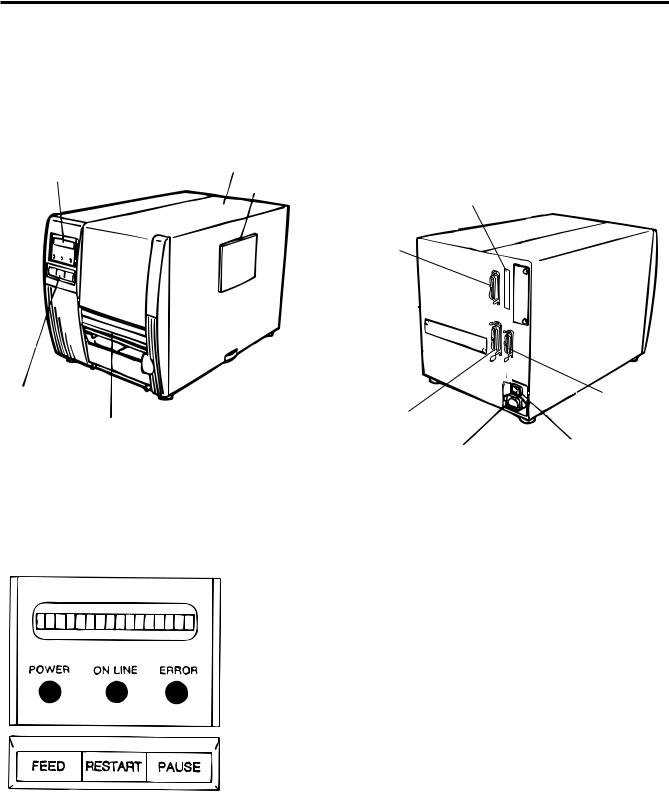
3.1 Front/Rear View
Front View |
Rear View |
Message Display (LCD)
Operation Panel
Media Outlet
Top Cover
Supply Window
PCMCIA Card Slot (2 slots)
Serial Interface Connector (RS-232C)
Parallel I/F Connector |
Expansion I/O |
Interface Connector |
|
(Centronics) |
(Option) |
AC Power Inlet |
Power Switch |
|
0: OFF |
||
|
||
Fig. 3-1 |
1: ON |
|
|
3.2 Operation Panel
Fig. 3-2
MESSAGE DISPLAY (LCD)
When power is turned on and it is ready to print, "ON LINE" is displayed.
POWER LED (Green)
Lights when the power is turned on.
ON-LINE LED (Green)
1)Flashes when communicating with a host computer.
2)On while printing.
ERROR LED (Red)
Lights when a communication error occurs, when the media/ ribbon ends or the printer does not operate correctly.
FEED key
Feeds paper.
RESTART key
Resets the printer when paused or when an error occurs. Used to set the threshold. (Refer to page 9-4)
PAUSE key
Pauses printing.
Message display shows "PAUSE" and an unprinted count. Used to set the threshold. (Refer to page 9-4)
E3-1
4. INSTALLING THE PRINTER
ENGLISH VERSION EO1-33007
4.1 Connecting the Power Cord and Cables
4. INSTALLING THE PRINTER
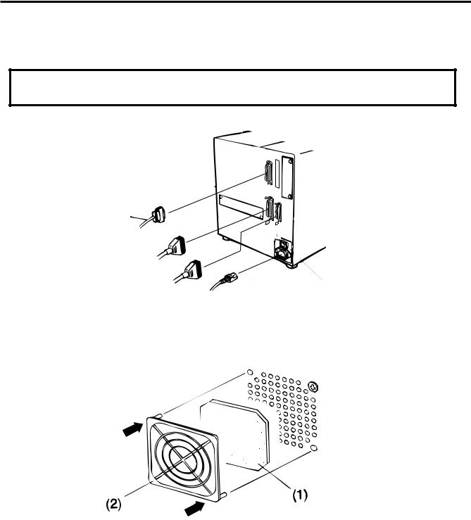
4.1 Connecting the Power Cord and Cables
WARNING:
Turn the POWER SWITCH to OFF before connecting the power cord or cables.
Serial I/F Cable (RS-232C)
Parallel I/F Cable (Centronics)
Expansion I/O Cable (Option)
Power Cord |
Fig. 4-1 |
|
4.2 Procedure for Fitting Fan Filter
Snap on
Snap on
Fig. 4-2
When installing the printer, it is important to ensure that the fan filter is attached before using the printer. The filter comes in 2 parts:
(1)FILTER PAD
(2)FILTER RETAINER
To fit put the filter pad inside the filter retainer and simply press into place according to the diagram above, ensuring connecting pins are aligned with connecting holes.
E4-1
5. LOADING THE MEDIA
ENGLISH VERSION EO1-33007
5. LOADING THE MEDIA
5. LOADING THE MEDIA
WARNING:
1.Do not touch moving parts. To reduce the risk that fingers, jewelry, clothing, etc., be drawn into the moving parts, push the switch in the “OFF” position to stop movement.
2.To avoid injury, be careful not to catch or jam your fingers while opening or closing the cover.
The printer prints both labels and tags.
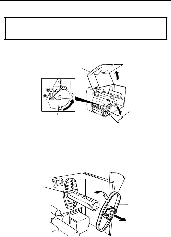
1.Turn off the power and open the top cover.
2.Turn the head lever to position 3, then release the ribbon shaft holder plate.
Top Cover
Ribbon Shaft Holder Plate
Head Lever
Fig. 5-1
NOTES: 1. When the head lever is turned to position 2, the print head is raised.
2.When the head lever is turned to position 3, the print head and the pinch roller are raised.
3.To allow printing the head lever must be set to position 1. (This ensures that the print head and the pinch roller are closed.)
3.Untape the supply holder.
4.Turn the outside supply holder 30 degrees and remove from the supply shaft.
30
Supply Shaft
Supply Holder (FMHD0005502)
Fig. 5-2
NOTE: Set the inside supply holder to the scale on the shaft according to media to be used.
E5-1
5. LOADING THE MEDIA
ENGLISH VERSION EO1-33007
5. LOADING THE MEDIA
5.Put the media on the supply shaft.
6.Pass the media around the damper, then pull the media towards the front of the printer. Fix the remaining supply holder to the supply shaft with the pinchers facing away from the printer.
Damper
Media
Supply Holder (FMHD0005502)
Supply Shaft
Fig. 5-3
7.Insert the media into the paper holders of the media guide, adjust the media guides to the media width, and tighten the locking screw.
8.Check that the media path through the printer is straight. The media should be centered under the print head.
Media Guide |
|
Media |
Supply Holder |
|
Media Guide |
|
Paper Holder |
Paper Holder |
Print Head |
Locking Screw |
Media |
Fig. 5-4
NOTE: When using the label rolled with labels facing outside, please remove the upper plates of both paper holders using the following procedure. Failure to do this may cause a paper jam error.
If you have any questions, please contact your nearest TOSHIBA TEC service representative.
E5-2
5. LOADING THE MEDIA
ENGLISH VERSION EO1-33007
5. LOADING THE MEDIA
■ Removing the paper holders' upper plates from the media guide
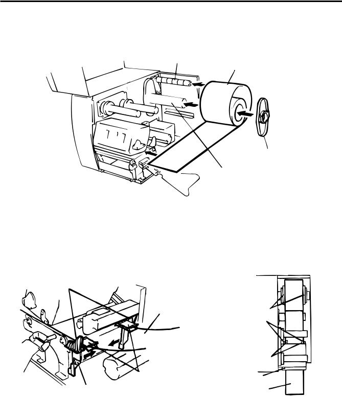
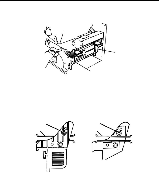
1 Remove the two T-4x8 screws to detach the media guide from the printer.
Media Guide
 Screw (T-4x8)
Fig. 5-5
2Remove the SM-3x6 screw or the SM-3x8 screw to detach the paper holders' upper plates from the media guide.
(Right) |
(Left) |
Screw (SM-3x6) |
Screw (SM-3x8) |
Paper Holder |
Paper Holder |
Fig. 5-6
3 Attach the media guide back in position.
NOTE: Do not lose the removed upper plates because they are required when using the label rolled with labels facing inside.
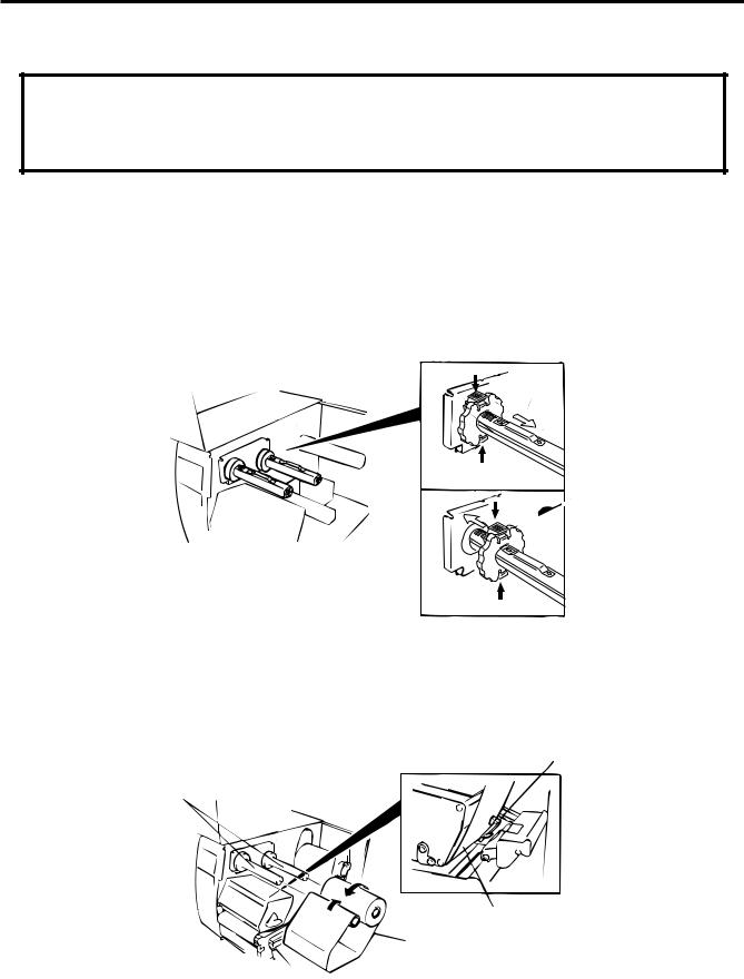
9.Set the black mark/feed gap sensor to the correct position by turning the adjusting knob. Turning the knob right will move the sensor towards the center of the media while turning left will move it away from the center of the media.
E5-3

5. LOADING THE MEDIA
ENGLISH VERSION EO1-33007
5. LOADING THE MEDIA
■An easy way to set the black mark sensor position
1 Pull the media about 500 mm out of the front of the printer, turn the media back on it's self and feed it under the print head past the sensor so that the black mark can be seen from above.
2Adjust the sensor position to that of the black mark (the upper hole indicates the position of the black mark sensor).
Black Mark Sensor |
Black Mark |
Media
(Feed Gap Sensor)
Adjusting Knob
Fig. 5-7
NOTE: Make sure to set the sensor to detect the center of the black mark, otherwise a paper jam error could occur.
■Setting the feed gap sensor position
1 Adjust the sensor to detect on the gap (the lower hole indicates the position of the feed gap sensor.)
(Black Mark Sensor)
Backing Paper
Media
Media
Feed Gap Sensor
Adjusting Knob
Fig. 5-8
E5-4
5. LOADING THE MEDIA
ENGLISH VERSION EO1-33007
5. LOADING THE MEDIA
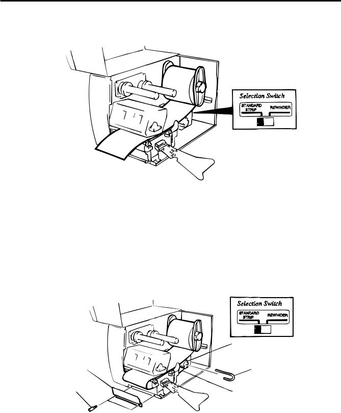
10. The media is now loaded and the sensor position is set.
Batch type:
Media
Fig. 5-9
NOTE: Set the selection switch to the STANDARD/STRIP position. Improper setting can affect the print quality.
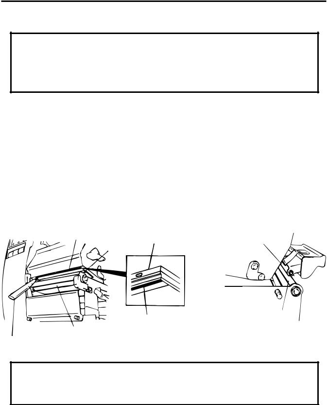
Strip type:
1 Remove enough labels from the leading edge media to leave 500 mm of backing paper exposed.
2 Wind the backing paper onto the take-up spool and fix in position with the take-up clip. (Wind the paper counter clockwise around the spool as this is the direction it rotates.)
3 Rotate the take-up spool anti-clockwise a few times to take up any slack in the backing paper.
|
Media |
|
Take-up Spool |
Front Plate |
Take-up Clip |
Black Screw |
|
(HAA-0004001) |
Backing Paper |
|
Fig. 5-10
NOTES: 1. The backing paper is easier to feed back to the take-up spool if the front plate is removed.
2.When fitting the tace-up clip the longer side of the clip should be fitted into the shallow groove on the take-up spool.
3.Set the selection switch to the STANDARD/STRIP position.
E5-5

5. LOADING THE MEDIA
ENGLISH VERSION EO1-33007
5. LOADING THE MEDIA
Cutter type: Where a cutter is fitted load the media as standard and feed it through the cutter module. Swing cutter and rotary cutter are available as an option. They are used in the same way regardless of different shapes. Now, how to load the media using the swing cutter will be introduced.
NOTES: 1. Be sure to cut the backing paper of label. Cutting labels will cause the glue to stick to the cutter, which may affect the cutter quality and shorten the life.
2.If a label winds onto the platen during cut issue, please contact your nearest TOSHIBA TEC service representative.
3.For the cutter type, the selection switch can be set to either position.
Media Outlet
Media
Cutter Module |
Fig. 5-11 |
Built-in rewinder type:
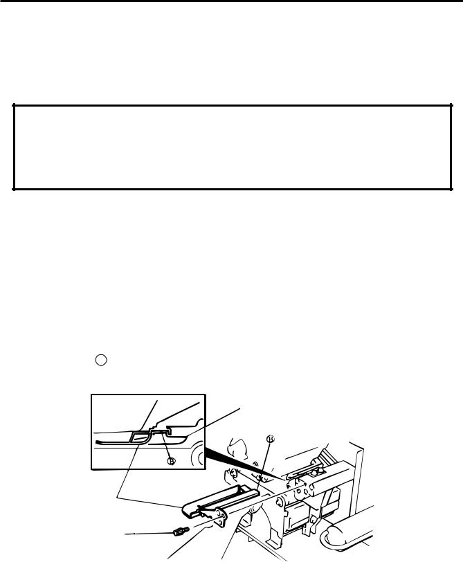
1 Remove two black screws and front plate.
2 Fit the rewinder guide plate to the strip shaft, then attach it with the sems screws.
Tear-off Bar
Rewinder Guide Plate (FMBD0034501)
SM-4x6B Sems Screw |
SM-4x6B Sems Screw |
SM-4x8 Sems Screw |
|
Adjustment Knob |
Fig. 5-12 |
NOTES: Set the selection switch to the REWINDER position.
3 Follow the procedure for strip type.
4Adjustment
If the label skews when using built-in rewinder unit, turn the adjustment knob of the rewinder guide plate to correct the label feed. Clockwise turn moves the rewinder guide plate forward and counterclockwise moves it backward.
*When labels skew to the right:
Loosen the SM-4x8 sems screw with a philips-head screw driver. Turn the adjustment knob clockwise, and tighten the SM-4x8 screw when the rewinder guide plate is positioned correctly.
*When labels skew to the left:
Loosen the SM-4x8 screw with a phillips-head screw driver. Turn the adjustment knob counterclockwise, and tighten the SM-4x8 screw when the rewinder guide plate is positioned correctly.
E5-6
6. LOADING THE RIBBON
ENGLISH VERSION EO1-33007
6. LOADING THE RIBBON
6. LOADING THE RIBBON
WARNING:
1.Do not touch moving parts. To reduce the risk that fingers, jewelry, clothing, etc., be drawn into the moving parts, push the switch in the “OFF” position to stop movement.
2.To avoid injury, be careful not to catch or jam your fingers while opening or closing the cover.
There are two types of media available for printing on, these are standard media and direct thermal media (a chemically treated surface). DO NOT LOAD a ribbon when using a direct thermal media.
1.When using a narrow width ribbon, slide the ribbon stoppers along the shafts to a position where the ribbon will be centered when it is fitted. When changing from a narrow width to a wider one rotate the ribbon stoppers by 90 , push them back to the correct position and then rotate back to lock.
NOTE: When attaching the ribbon stoppers, fit them to the shafts with the pinchers facing into the printer.
 Ribbon Stopper
 Ribbon Stopper
Fig. 6-1
2.Leaving plenty of slack between the spools, fit the ribbon as shown below. When the ribbon is fitted it must be positioned over the ribbon sensor.
3.Wind both shafts towards each other to tighten the ribbon.
Ribbon Sensor
Ribbon Shafts
Ribbon
Ribbon
Fig. 6-2
4.Reset the ribbon shaft holder plate by aligning it with the ribbon shaft.
5.Turn the head lever clockwise to lower the print head.
6.Close the top cover.
E6-1
7. INSERTING THE OPTIONAL PCMCIA CARD
ENGLISH VERSION EO1-33007
7. INSERTING THE OPTIONAL PCMCIA CARD
7. INSERTING THE OPTIONAL PCMCIA CARD
WARNING:
Turn the power OFF when inserting or removing the PCMCIA card.
CAUTION:
To protect PCMCIA cards, discharge static electricity from your body by touching the printer rear cover prior touching the PCMCIA cards.
1.Turn the power off.
2.Insert the PCMCIA card into the card slot at the rear of the printer.
3. Turn the power on. |
1 |
0 |
|
PCMCIA Card
Fig. 7-1
NOTES: 1. Be sure to protect a PCMCIA card when not in use in the printer by putting it in its protective cover.
2.Do not subject the card to any shocks or excessive forces.
3.Do not expose the card to extremes of heat by either storing in direct sunlight or close to a heater.
4.Do not expose the card to excessive humidity by wiping it with a wet cloth or storing it in a damp place.
5.Before inserting or removing the card, make sure that the power switch is turned off.
6.The following flash cards can be used. (The 1MB-card is read only and the 4MB card can read/ write.)
Capacity |
Maker |
Type |
Device code |
Maker code |
|
1M Byte |
Maxell |
EF-1M-TB AA |
D0H |
1CH |
|
|
|
Mitsubishi |
MF81M1-GBDAT01 |
|
|
4M Byte |
Maxell |
EF-4M-TB CC |
88H |
B0H |
|
|
|
Maxell |
EF-4M-TB DC |
ADH |
04H |
|
|
Centennial Technologies INC. |
FL04M-15-11119-03 |
|
01H |
|
|
INTEL |
IMC004FLSA |
A2H |
89H |
|
|
Simple TECHNOLOGY |
STI-FL/4A |
|
|
|
|
|
|
|
|
|
|
Mitsubishi |
MF84M1-G7DAT01 |
|
|
|
|
|
|
|
|
|
|
PC Card KING MAX |
FJN-004M6C |
|
|
|
|
|
|
|
|
|
|
PC Card |
FJP-004M6R |
A0H |
89H |
|
|
|
|
|
|
7. Install the LAN card into the slot (1).
E7-1

8. CARE/HANDLING OF THE MEDIA AND RIBBON |
ENGLISH VERSION EO1-33007 |
8. CARE/HANDLING OF THE MEDIA AND RIBBON
8. CARE/HANDLING OF THE MEDIA AND RIBBON
CAUTION:
Be sure to read carefully and understand the Supply Manual. Use only media and ribbon which meet specified requirements. Use of non-specified media and ribbon may shorten the head life and result in problems with bar code readability or print quality. All media and ribbon should be handled with care to avoid any damage to the media, ribbon or printer. Read the following guideline carefully.
•Do not store the media and ribbon for longer than the manufactures recommended shelf life.
•Store media rolls on the flat end, do not store them on the curved sides as this might flatten that side causing erratic media advance and poor print quality.
•Store the media in plastic bags and always reseal after opening. Unprotected media can get dirty and the extra abrasion from the dust and dirt particles will shorten the print head life.
•Store the media and ribbon in a cool, dry place. Avoid areas where they would be exposed to direct sunlight, high temperature, high humidity, dust or gas.
•The thermal paper used for direct thermal printing must not have the specifications which exceed Na+ 800 ppm, K+ 250 ppm and CL- 500 ppm.
•Some ink used on pre-printed labels may contain ingredients which shorten the print head's product life.
Do not use labels pre-printed with ink which contain hard substances such as carbonic calcium (CaCO3) and kaolin (Al2O3, 2SiO2, 2H2O).
For further information please contact your local distributor or your media and ribbon manufacturer.
E8-1
9. GENERAL MAINTENANCE
ENGLISH VERSION EO1-33007
9.1 Cleaning
9. GENERAL MAINTENANCE
WARNING:
1.Be careful when handling the print head as it becomes very hot.
2.Care must be taken not to injure yourself with the printer paper cutter.
3.Do not touch moving parts. To reduce the risk that fingers, jewelry, clothing, etc., be drawn into the moving parts, push the switch in the “OFF” position to stop movement.
4.To avoid injury, be careful not to catch or jam your fingers while opening or closing the cover.
9.1Cleaning
To help retain the high quality and performance of your printer it should be regularly cleaned. The greater the usage of the printer, the more frequent the cleaning. (i.e. low usage=weekly : high usage=daily). A print head cleaner is not enclosed with the printer, so please inquire at your local distributor.
1.Turn the power off.
2.Open the top cover.
3.Turn the head lever to raise the print head.
4.Remove the ribbon and media.
5.Clean the element of print head with print head cleaner.
6.Wipe the platen, feed roller and pinch roller with a cleaner moistened with alcohol. Remove dust or foreign substances from the internal part of the printer, if any.
Element |
Pinch Roller |
Print Head |
|
Print Head |
|
|
Element |
Feed Roller |
|
|
|
|
Platen |
|
Print Head Cleaner |
|
Fig. 9-1 |
(24089500013) |
|
WARNING:
1.Be sure to disconnect the power cord prior ot performing any maintenance.
2.Do not use any tool that may damage the print head.
3.DO NOT POUR WATER directly onto the printer.
E9-1
9. GENERAL MAINTENANCE
ENGLISH VERSION EO1-33007
9.2 Covers and Panels
9.2 Covers and Panels
The covers should be cleaned by wiping with a dry cloth or a cloth slightly dampened with a mild detergent
solution.
NOTE: Clean the printer cover with an electrostatic free cleaner for automated office equipment.
WARNING:
1.DO NOT POUR WATER directly onto the printer.
2.DO NOT APPLY cleaner or detergent directly onto any cover or panel.
3.NEVER USE THINNER OR OTHER VOLATILE SOLBENT on the plastic covers.
4.DO NOT clean the panel covers or the supply window with alcohol as it may cause them to discolor, loose their shape or develop structural weakness.
9.3Removing Jammed Paper
1.Turn the power off.
2.Open the top cover.
3.Turn the head lever to position 3, then release the ribbon shaft holder plate.
4.Remove the flanged screw to detach the media guide plate. (See Fig. 9-2.)
5.Remove the ribbon and media.
6.Remove the jammed paper. DO NOT USE any sharp implement or tool as these could damage the printer.
7.Clean the print head and platen, then remove any further dust or foreign substances.
8.Place the portion B of the media guide plate on the media sensor. Secure the media guide plate with the flanged screw.
Media Sensor
Media Guide Plate
Flanged Screw
FL-4x 12
Fig. 9-2
9.Paper jams in the cutter unit can be caused by wear or residual glue from label stock on the cutter. Do not use none specified media in the cutter. If you get frequent jams in the cutter contact your Authorized Service representative.
E9-2
9. GENERAL MAINTENANCE
■ Cleaning the Cutter Unit
WARNING:
ENGLISH VERSION EO1-33007
9.3 Removing Jammed Paper
1.Be sure to turn the power off before cleaning the cutter unit.
2.The cutters are sharp and care should be taken not to injure yourself when cleaning.
The swing cutter and rotary cutter are available as an option. They are both cleaned in the same way regardless of different shapes. Now, how to clean the cutter unit installing the swing cutter will be introduced.
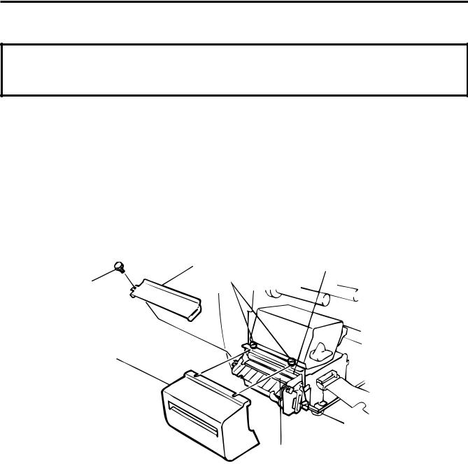
1.Loosen two screws and remove the cutter cover.
2.Remove the white screw and media guide.
3.Remove the jammed paper and trash.
4.Clean the cutter with dry cloth.
5.Assembling is reverse order of removal.
Media Guide |
Fixed Cutter |
Screw |
|
White Screw (24741710304)
Cutter Cover
Cutter Unit
Swing Cutter
Fig. 9-3
E9-3
9. GENERAL MAINTENANCE
ENGLISH VERSION EO1-33007
9.4 Threshold Setting
9.4 Threshold Setting
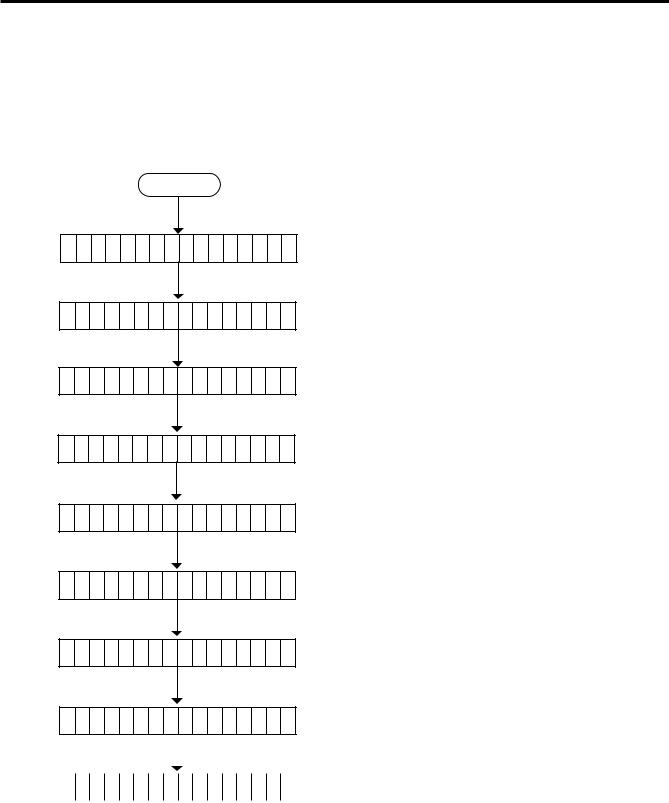
For the printer to maintain a constant print position it uses the feed gap sensor to detect the gap between labels by measuring the amount of light passing through the media. When the media is pre-printed, the darker (or more dense) inks can interfere with this process causing paper jammed errors. To get around this problem a minimum threshold can be set for the sensor in the following way.
■ Threshold setting procedure
Power on
O N L I N E
[PAUSE] key.
P A U S E
[PAUSE] key.
T R A N S M I S S I V E
(1)Online
(2)Load the preprinted label. (No particular positioning is required.)
(3)Press the [PAUSE] key.
(4)The printer is in the pause state.
(5)Press the [PAUSE] key for 3 seconds or more while the printer is paused.
(6)The sensor selection to set the threshold manually is displayed. The transmissive sensor designation is displayed.
[FEED] key. |
(7) Press the [FEED] key. |
R E F L E C T I V E
[FEED] key.
T R A N S M I S S I V E
[PAUSE] key.
T R A N S M I S S I V E
P A U S E
[RESTART] key.
O N L I N E

 Command
(8)The reflective sensor designation is displayed.
(9)Press the [FEED] key.
(10)The transmissive sensor designation is displayed.
(11)Press and hold the [PAUSE] key.
(12)The printer feeds labels until the [PAUSE] key is released.
(13)The [PAUSE] key should be held until more than 1.5 sheets of the label are fed. When the [PAUSE] key is released, the printer stops feeding the label. (Threshold setting for the selected sensor is completed.)
(14)Press the [RESTART] key.
(15)Online
O N L I N E |
(16) The label is printed according to the command issued from the |
|
PC. |
|
< Supplementary Explanation >
(1)When the [PAUSE] key is released within 3 seconds while printer pauses, the [PAUSE] key is invalid.
(2)When the threshold is programmed, 1.5 sheets of the label should be fed. (If less than 1.5 labels are fed, the threshold may not be properly programmed. In this case, reprogramming is required.)
(3)When the [PAUSE] key is pressed for 3 seconds or more in a head-up state, the [PAUSE] key is invalid.
(4)During a label feed, an error including the paper end, ribbon end or cutter error is not detected.
E9-4

9. GENERAL MAINTENANCE
ENGLISH VERSION EO1-33007
9.4 Threshold Setting
■ Auto Ribbon Saving Mode
Auto ribbon saving function is activated when a no print area extends more than 17 mm.
For further information on this function, please ask your nearest TOSHIBA TEC service representative.
NOTE: According to the relation between the outer diameter of rewound ribbon and print speed, ribbon loss per saving varies as follows:
Print speed |
Ribbon loss |
|
3"/sec. |
Approx. 5 mm |
|
5"/sec. |
Approx. 8 mm |
|
|
|
|
8"/sec. |
Approx. 17 mm |
|
E9-5

10. TROUBLESHOOTING
ENGLISH VERSION EO1-33007
10. TROUBLESHOOTING
10. TROUBLESHOOTING
WARNING:
If you cannot solve a problem with the following solutions, do not attempt to repair it yourself. Turn the power off, unplug the printer, then contact your Authorized Service representative for assistance.
Error Message |
Problem |
Solution |
|
|
|
PAPER JAM |
1. The media is not fitted correctly. |
1. Re-fit the media correctly. |
**** |
|
Press the [RESTART] key. |
|
2. The media path is jammed and |
2. Remove the cause of the jam and |
|
does not feed smoothly. |
replace the media correctly. |
|
|
Press the [RESTART] key. |
|
3. The installed media type does not |
3. Turn the power off then on again. |
|
match the selected sensor. |
Select the correct sensor. |
|
|
Feed the media. |
|
4. The black mark position on the |
4. Adjust the sensor position. |
|
media does not match the sensor |
Press the [RESTART] key. |
|
position. |
|
|
5. The installed media size is different |
5. Turn the power off then on again. |
|
from the programmed size. |
Set the correct media size. |
|
|
Feed the media. |
|
6. The feed gap sensor cannot see |
6. Set the threshold (see page 9-4). |
|
the difference between the print |
Else |
|
area and the gap. |
Turn the power off and call your |
|
|
Authorized Service representative. |
|
|
|
HEAD OPEN |
Feed or printing has been attempted |
Lower the print head. |
**** |
while the print head is raised. |
Press the [RESTART] key. |
|
|
|
NO PAPER |
The media has run out. |
Load new media. |
**** |
|
Press the [RESTART] key. |
|
|
|
NO RIBBON |
The ribbon has run out. |
Load a new ribbon. |
**** |
|
Press the [RESTART] key. |
|
|
|
REWIND FULL |
Too much backing paper or media is |
Remove the backing paper or media |
**** |
wound on the internal take-up spool. |
from the internal take-up spool. |
|
|
Then press the [RESTART] key. |
|
|
|
EXCESS HEAD |
The print head is too hot. |
Turn the power off and decrease the |
TEMP |
|
print head temperature. |
|
|
|
RIBBON ERROR |
There is a fault with the ribbon sensor. |
Turn the power off. Contact your Au- |
**** |
|
thorized Service representative. |
|
|
|
E10-1

10. TROUBLESHOOTING |
ENGLISH VERSION EO1-33007 |
|
10. TROUBLESHOOTING |
|
|
Error Message |
Problem |
Solution |
|||
|
|
|
|
|
|
CUTTER ERROR |
Media is jammed in the cutter. |
Remove the jammed media and feed |
|||
**** |
|
the undamaged media through the |
|||
|
|
|
|
|
cutter. |
|
|
|
|
|
Press the [RESTART] key. |
|
|
|
|
|
Else |
|
|
|
|
|
Turn the power off and contact your |
|
|
|
|
|
Authorized Service representative. |
|
|
|
|
|
|
FLASH WRITE |
An error has occurred when loading |
1. Turn the power off, re-seat the flash |
|||
ERR. |
data onto a flash memory card or ATA |
memory card or ATA card and try again. |
|||
|
|
|
|
card. |
2. Replace the flash memory card or |
|
|
|
|
|
ATA card and retry. |
|
|
|
|
|
3. Turn the power off and contact your |
|
|
|
|
|
Authorized Service representative. |
|
|
|
|
|
|
FORMAT ER- |
An error has occurred while formatting |
1. Turn the power off, re-seat the flash |
|||
ROR |
a flash memory card or ATA card. |
memory card or ATA card and try again. |
|||
|
|
|
|
|
2. Replace the flash memory card or |
|
|
|
|
|
ATA card and retry. |
|
|
|
|
|
3. Turn the power off and contact your |
|
|
|
|
|
Authorized Service representative. |
|
|
|
|
|
|
FLASH CARD |
No more data can be saved in the |
Replace the card with a new one and |
|||
FULL |
flash memory card or ATA card. |
re-send data. |
|||
|
|
|
|
|
(In case of flash memory card, only |
|
|
|
|
|
1MB and 4MB cards can be used.) |
|
|
|
|
|
|
COMMS ERROR |
A communication error has occurred |
Turn the power off then on again or |
|||
|
|
|
|
with the host. |
press the [RESTART] key. |
|
|
|
|
|
Check the program data. |
|
|
|
|
|
Call your Authorized Service repre- |
|
|
|
|
|
sentative if necessary. |
|
|
|
|
|
|
example) |
When an error is detected in a com- |
Correct the command and re-send it |
|||
PC001; 0A00, |
mand 16 bytes of the command are |
again. |
|||
|
|
|
|
displayed. |
|
Command error |
(ESC, LF, NUL are not displayed.) |
|
|||
0300, 2, 2 |
|
|
|||
|
|
|
|||
Other Error |
Hardware or software trouble. |
Turn the power off then on again. If the |
|||
Message |
|
problem still exists turn the power off |
|||
|
|
|
|
|
and contact your Authorized Service |
|
|
|
|
|
representative. |
|
|
|
|
|
|
NOTE: If an error is not cleared by pressing the [RESTART] key, the power must be switched off then on again.
After the power has been switched off and on, all print data in the printer is cleared.
**** denotes a remaining count of unprinted labels.
E10-2
10. TROUBLESHOOTING |
ENGLISH VERSION EO1-33007 |
|
10. TROUBLESHOOTING |
|
|
Problem |
|
Solution |
|
|
|
No print. |
1. |
Check that media and the ribbon is loaded correctly. |
|
2. |
Check whether the print head is set correctly or not. |
|
3. |
Check the cabling between the printer and the host. |
|
|
|
Dots missing in the print. |
Dirty print head. Clean the print head. |
|
|
Call your Authorized Service representative if necessary. |
|
|
|
|
Unclear (or blurred) printing. |
1. |
Dirty print head. Clean the print head. |
|
2. |
Bad or faulty ribbon. Replace ribbon. |
|
3. |
Poor media quality. Change media type. |
|
|
|
Power does not come on. |
1. |
Plug power cord into an AC socket. |
|
2. |
Check the circuit breakers or fuses. |
|
3. |
Plug another appliance into the AC socket to check if |
|
|
there is power supplied. |
|
Call your Authorized Service representative if necessary. |
|
|
|
|
Printer does not cut. |
Check for a paper jam in the cutter. |
|
|
Call your Authorized Service representative if necessary. |
|
|
|
|
You see a raised nap where the media |
1. |
Clean the cutter blades. |
has been cut. |
2. |
The blades are worn. |
|
|
Call your Authorized Service representative. |
|
|
|
E10-3
Loading...