


ASD-G9ETH
ASD INTERFACE SERIES
ICC
INDUSTRIAL CONTROL COMMUNICATIONS, INC.
ASD-G9ETH
MULTIPROTOCOL ETHERNET INTERFACE FOR
TOSHIBA G9 / VFAS1 ADJUSTABLE SPEED DRIVES
June 2011
ICC #10639-2.300-000

ICC
ASD-G9ETH Multiprotocol Ethernet Interface
User's Manual
Part Number 10639-2.300-000
Printed in U.S.A.
©2007-2011 Industrial Control Communications, Inc.
All rights reserved
N
OTICE TO USERS
Industrial Control Communications, Inc. reserves the right to make changes and
improvements to its products without providing notice.
Industrial Control Communications, Inc. shall not be liable for technical or editorial
omissions or mistakes in this manual, nor shall it be liable for incidental or
consequential damages resulting from the use of information contained in this
manual.
INDUSTRIAL CONTROL COMMUNICATIONS, INC.’S PRODUCTS ARE NOT
AUTHORIZED FOR USE AS CRITICAL COMPONENTS IN LIFE-SUPPORT
DEVICES OR SYSTEMS. Life-support devices or systems are devices or systems
intended to sustain life, and whose failure to perform, when properly used in
accordance with instructions for use provided in the labeling and user's manual, can
be reasonably expected to result in significant injury.
No complex software or hardware system is perfect. Bugs may always be present in
a system of any size. In order to prevent danger to life or property, it is the
responsibility of the system designer to incorporate redundant protective
mechanisms appropriate to the risk involved.
This user’s manual may not cover all of the variations of interface applications, nor
may it provide information on every possible contingency concerning installation,
programming, operation, or maintenance.
The contents of this user’s manual shall not become a part of or modify any prior
agreement, commitment, or relationship between the customer and Industrial Control
Communications, Inc. The sales contract contains the entire obligation of Industrial
Control Communications, Inc. The warranty contained in the contract between the
parties is the sole warranty of Industrial Control Communications, Inc., and any
statements contained herein do not create new warranties or modify the existing
warranty.
Any electrical or mechanical modifications to this equipment without prior written
consent of Industrial Control Communications, Inc. will void all warranties and may
void any UL/cUL listing or other safety certifications. Unauthorized modifications may
also result in equipment damage or personal injury.
1

s
ICC
Usage Precautions
Operating Environment
• Please use the interface only when the ambient temperature of the
environment into which the unit is installed is within the following
specified temperature limits:
Operation: -10 ∼ +50°C (+14 ∼ +122°F)
Storage: -40 ∼ +85°C (-40 ∼ +185°F)
• Avoid installation locations that may be subjected to large shocks or
vibrations.
• Avoid installation locations that may be subjected to rapid changes in
temperature or humidity.
Installation and Wiring
• Proper ground connections are vital for both safety and signal reliability
reasons. Ensure that all electrical equipment is properly grounded.
• Route all communication cables separate from high-voltage or noise-
emitting cabling (such as ASD input/output power wiring).
ASD Connection
• Do not touch charged parts of the drive such as the terminal block
while the drive’s CHARGE lamp is lit. A charge will still be present in
the drive’s internal electrolytic capacitors, and therefore touching these
areas may result in an electrical shock. Always turn the drive’s input
power supply OFF, and wait at least 5 minutes after the CHARGE lamp
has gone out before connecting communication cables.
• For further drive-specific precaution, safety and installation information,
please refer to the appropriate documentation supplied with your drive.
• Internal ASD EEPROMs have a limited life span of write cycles.
Observe all precautions contained in this manual and your ASD
manual regarding which drive registers safely may and may not be
repetitively written to.
2

ICC
TABLE OF CONTENTS
1. Introduction ................................................................................... 6
2. Features ......................................................................................... 7
3. Precautions and Specifications .................................................. 9
3.1 Installation Precautions ......................................................................... 9
3.2 Maintenance Precautions .................................................................... 10
3.3 Inspection ............................................................................................ 11
3.4 Storage................................................................................................ 11
3.5 Warranty .............................................................................................. 11
3.6 Disposal .............................................................................................. 11
3.7 Environmental Specifications .............................................................. 12
4. Interface Board Overview .......................................................... 13
5. Installation ................................................................................... 14
5.1 Installation Procedure .......................................................................... 14
5.2 Installing Multiple Option Cards ........................................................... 16
6. LED Indicators ............................................................................ 17
6.1 Front Panel .......................................................................................... 17
6.2 Ethernet Jack ...................................................................................... 18
7. Configuring the IP Address ....................................................... 19
7.1 Via the Finder Utility ............................................................................ 19
7.2 Via the Drive’s Keypad ........................................................................ 20
7.3 Via the Web Page ............................................................................... 20
8. Using the ICC Finder Utility ....................................................... 21
9. Parameter Numbering ................................................................ 22
10. Embedded Web Server ........................................................... 24
10.1 Overview ............................................................................................. 24
10.2 Authentication ..................................................................................... 25
10.3 Page Select Tabs ................................................................................ 25
10.4 Monitor Tab ......................................................................................... 26
10.4.1 Information Window .................................................................... 26
10.4.2 Parameter Group Selection List .................................................. 26
10.4.3 Parameter Subgroup Selection List ............................................ 27
10.4.4 Parameter List ............................................................................ 27
3

ICC
10.4.5 Parameter List Filter ................................................................... 28
10.4.6 Radix Selection........................................................................... 29
10.5 PROFINET Tab ................................................................................... 30
10.5.1 Information Window .................................................................... 30
10.5.2 Device Identification and Configuration ...................................... 31
10.5.3 I/O Data Configuration Arrays .................................................... 31
10.5.4 Submitting Changes ................................................................... 32
10.6 BACnet Tab ......................................................................................... 33
10.6.1 Information Window .................................................................... 33
10.6.2 Device Identifiers ........................................................................ 34
10.6.3 Submitting Changes ................................................................... 34
10.7 Config Tab ........................................................................................... 35
10.7.1 Information Window .................................................................... 35
10.7.2 Drive Configuration Parameter Write Selection .......................... 36
10.7.3 Authentication Configuration....................................................... 36
10.7.4 IP Address Configuration ............................................................ 37
10.7.5 Timeout Configuration ................................................................ 37
10.7.6 Submitting Changes ................................................................... 38
10.8 EtherNet/IP Tab .................................................................................. 39
10.8.1 Information Window .................................................................... 39
10.8.2 Device Identification ................................................................... 40
10.8.3 Run/Idle Flag Behavior ............................................................... 40
10.8.4 Class 1 (I/O) Data Configuration Arrays ..................................... 40
10.8.5 Submitting Changes ................................................................... 41
10.9 Alarm Tab............................................................................................ 43
10.9.1 Information Window .................................................................... 44
10.9.2 Email Configuration .................................................................... 44
10.9.3 Alarm Configuration .................................................................... 45
10.9.4 Submitting Changes ................................................................... 47
10.10 Modbus Tab .................................................................................... 48
10.10.1 Information Window .................................................................... 48
10.10.2 Supervisory Timer Selection ....................................................... 49
10.10.3 Register Remap Configuration ................................................... 49
10.10.4 Submitting Changes ................................................................... 50
10.11 Dashboard Tab ............................................................................... 51
10.11.1 Information Window .................................................................... 52
10.11.2 Gauge Window Navigation ......................................................... 52
10.11.3 Gauge Window Configuration ..................................................... 52
10.11.4 Submitting Changes ................................................................... 56
11. Interacting With the Filesystem ............................................. 57
11.1 Initiating FTP via the Finder Utility ....................................................... 58
4

ICC
11.2 Using FTP with Windows Explorer ...................................................... 59
11.3 Using FTP with a Windows Command Prompt .................................... 60
11.4 Using FTP with Core FTP LE .............................................................. 62
12. Loading New Application Firmware ..................................... 64
13. Protocol-Specific Information ............................................... 66
13.1 Modbus/TCP ....................................................................................... 66
13.1.1 Overview .................................................................................... 66
13.1.2 Coil & Discrete Input Mappings .................................................. 67
13.2 EtherNet/IP .......................................................................................... 69
13.2.1 Overview .................................................................................... 69
13.2.2 ODVA AC/DC Drive Profile ......................................................... 70
13.2.3 ControlLogix Examples: Setup ................................................... 73
13.2.4 ControlLogix Example: I/O Messaging ....................................... 75
13.2.5 ControlLogix Example: Generic Default I/O Add-On Instruction . 78
13.2.6 ControlLogix Example: AC/DC Drive Profile Add-On Instruction 81
13.2.7 Explicit Messaging Tag Reference ............................................. 83
13.2.8 ControlLogix Example: Read a Register Block ........................... 85
13.2.9 ControlLogix Example: Read a Single Register .......................... 91
13.2.10 ControlLogix Example: Multiple MSG Instructions ...................... 91
13.2.11 ControlLogix Example: Reading and Writing .............................. 92
13.3 Allen Bradley CSP ............................................................................... 94
13.3.1 Tag Reference ............................................................................ 94
13.3.2 SLC-5/05 Example: Read a Register Block ................................ 95
13.3.3 SLC-5/05 Example: Read a Single Register ............................. 100
13.3.4 SLC-5/05 Example: Multiple MSG Instructions ......................... 101
13.3.5 SLC-5/05 Example: Reading and Writing ................................. 102
13.4 BACnet .............................................................................................. 104
13.4.1 Overview .................................................................................. 104
13.4.2 Protocol Implementation Conformance Statement ................... 104
13.4.3 Supported Objects .................................................................... 108
13.4.4 Supported Object Details .......................................................... 110
13.5 PROFINET IO ................................................................................... 113
13.5.1 Overview .................................................................................. 113
13.5.2 PROFIdrive Profile.................................................................... 114
5

ICC
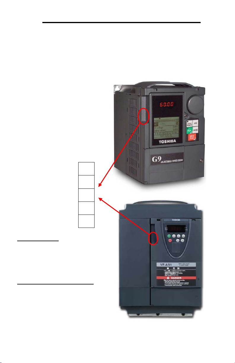
1. Introduction
Congratulations on your purchase of the ICC Multiprotocol Ethernet Interface for the
Toshiba G9, H9, Q9 and VFAS1 families of Adjustable Speed Drives (ASDs). This
interface allows information to be transferred seamlessly between the drive and
several different Ethernet-based fieldbus networks with minimal configuration
requirements. The interface installs directly into the drive enclosure and presents a
standard 10/100BaseT Ethernet port for connection to the Ethernet network. In
addition to the supported fieldbus protocols, the interface also hosts an embedded
web server, which provides access to all drive information via a standard web
browser for remote monitoring, configuration and control.
Before using the interface, please familiarize yourself with the product and be sure to
thoroughly read the instructions and precautions contained in this manual. In
addition, please make sure that this instruction manual is delivered to the end user of
the interface and ASD, and keep this instruction manual in a safe place for future
reference or unit inspection.
For the latest information, support software and firmware releases, please visit
http://www.iccdesigns.com.
Before continuing, please take a moment to ensure that you have received all
materials shipped with your kit. These items are:
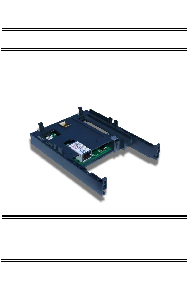
• Ethernet interface in plastic housing
• Documentation CD-ROM
Note that different interface firmware versions may provide varying levels of support
for the various protocols. When using this manual, therefore, always keep in mind
that the firmware version running on your interface must match this manual’s
respective revision in order for all documented aspects to apply.
This manual will primarily be concerned with the interface board’s hardware
specifications, installation, wiring, configuration and operational characteristics. For
more advanced ASD application-level information, please contact Toshiba’s ASD
Marketing Department for copies of available application notes.
To maximize the abilities of your new ASD interface, a working familiarity with this
manual will be required. This manual has been prepared for the interface installer,
user, and maintenance personnel. With this in mind, use this manual to develop a
system familiarity before attempting to install or operate the interface or ASD.
6

ICC
2. Features
Ethernet Port
IEEE 802.3 10/100BaseT Ethernet compliant. Shielded RJ45 connector accepts
standard CAT5-type 8-conductor unshielded twisted-pair (UTP) patch cables.
Supports multiple simultaneous protocols.
Supported Protocols
The interface currently provides server support for the following fieldbus protocols:
• Modbus TCP
• EtherNet/IP
• Allen Bradley CSP (also known as “PCCC” and “AB Ethernet”)
• BACnet/IP
• PROFINET IO
Note that use of PROFINET IO is mutually exclusive of the other supported
protocols. In order to use PROFINET IO, a separate application firmware file must
be loaded into the interface (refer to section 12).
Adobe® Flash-Enabled Embedded Web Server
Interface configuration and real-time drive parameter monitoring & control are
provided via an embedded web server. The interface’s web server feature provides
direct data access and control via standard web browsers such as Microsoft Internet
Explorer and Mozilla Firefox. The latest version of Adobe Flash Player browser plugin is required. Refer to section 10.
XML Configuration File Upload/Download
All interface configuration files are stored in the unit’s internal filesystem in XML
format. These files can be transferred to/from a PC via the FTP protocol, which
provides the capability for PC-based file backup and easy configuration copying to
multiple units. Configuration files can also be viewed and edited via standard text
editors, XML editors and web browsers. Refer to section 11.
Email-Based Alarm Notifications
Up to 20 configurable alarm conditions can be programmed into the interface. Value,
logical comparison and time-based conditions can be provided for the interface to
autonomously monitor any available drive register. When an alarm condition is
triggered, a notification email can be sent to up to four destination email addresses.
Refer to section 10.9.
Dashboard GUI
A dashboard tab on the embedded web server provides 10 gauge windows, each of
which can be configured to display any available drive register in a variety of meter,
graph and gauge formats. Refer to section 10.11.
7

ICC
Network Timeout Action
A configurable network timeout action can be programmed that allows registers to
have their own unique "fail-safe" conditions in the event of a network interruption.
Refer to section 10.7.5.
Field-Upgradeable
As new firmware becomes available, the interface can be upgraded in the field by the
end-user. Refer to section 12 for more information.
EtherNet/IP Data Access Options
The EtherNet/IP protocol provides access to inverter data via explicit messaging,
user-defined I/O assembly instances, and the ODVA AC/DC drive profile. Refer to
section 13.2 for more information.
PROFINET Data Access Options
The PROFINET protocol provides access to drive data via acyclic services, userdefined cyclic I/O modules, and the PROFIdrive profile. Refer to section 13.5 for
more information.
8

ICC
3. Precautions and Specifications
Rotating shafts and electrical equipment can be hazardous. Installation,
operation, and maintenance of the ASD and interface board shall be
performed by Qualified Personnel only.
Qualified Personnel shall be:
• Familiar with the construction and function of the ASD and interface
board, the equipment being driven, and the hazards involved.
• Trained and authorized to safely clear faults, ground and tag
circuits, energize and de-energize circuits in accordance with
established safety practices.
• Trained in the proper care and use of protective equipment in
accordance with established safety practices.
Installation of ASD systems and associated interface boards should
conform to all applicable National Electrical Code (NEC)
Requirements For Electrical Installations, all regulations of the
Occupational Safety and Health Administration, and any other
applicable national, regional, or industry codes and standards.
DO NOT install, operate, perform maintenance, or dispose of this
equipment until you have read and understood all of the following
product warnings and user directions. Failure to do so may result in
equipment damage, operator injury, or death.
3.1 Installation Precautions
• Use lockout/tagout procedures on the branch circuit disconnect
before installing the interface board into the ASD.
• Avoid installation in areas where vibration, heat, humidity, dust,
metal particles, or high levels of electrical noise (EMI) are present.
• Do not install the ASD or interface board where it may be exposed
to flammable chemicals or gasses, water, solvents, or other fluids.
• Where applicable, always ground the interface board appropriately
to prevent electrical shock to personnel and to help reduce electrical
noise. The ASD’s input, output, and control power cables are to be
run separately from the interface board’s associated cables.
Note: Conduit is not an acceptable ground.
• Turn the power on only after attaching the front cover.
9

ICC
• Follow all warnings and precautions and do not exceed equipment
ratings.
• The ASD maintains a residual charge for a while after turning supply
power off. After turning supply power off, wait at least ten minutes
before servicing the ASD or interface board. Ensure that the
Charge LED is off prior to beginning installation.
• For further ASD-specific precaution, safety and installation
information, please refer to the applicable Adjustable Speed Drive
Operation Manual supplied with your ASD.
3.2 Maintenance Precautions
• Use lockout/tagout procedures on the branch circuit disconnect
before servicing the ASD or installed interface board.
• The ASD maintains a residual charge for a while after turning supply
power off. After turning supply power off, wait at least ten minutes
before servicing the ASD or interface board. Ensure that the
Charge LED is off prior to beginning maintenance.
• Do Not attempt to disassemble, modify, or repair the interface
board. Contact your ICC or Toshiba sales representative for repair
or service information.
• Turn the power on only after attaching the front cover and Do Not
remove the front cover of the ASD when the power is on.
• If the ASD should emit smoke or an unusual odor or sound, turn the
power off immediately.
• The ASD heat sink and discharge resistors may become extremely
hot to the touch. Allow the unit to cool before coming into contact or
performing service on the ASD or interface board.
• The system should be inspected periodically for damaged or
improperly functioning parts, cleanliness, and to determine that all
connectors are tightened securely.
10

ICC
3.3 Inspection
Upon receipt, perform the following checks:
• Inspect the unit for shipping damage.
• Check for loose, broken, damaged or missing parts.
Report any discrepancies to your ICC or Toshiba sales representative.
3.4 Storage
• Store the device in a well ventilated location (in its shipping carton, if possible).
• Avoid storage locations with extreme temperatures, high humidity, dust, or metal
particles.
3.5 Warranty
This communication interface is covered under warranty by ICC, Inc. for a period of
12 months from the date of installation, but not to exceed 18 months from the date of
shipment from the factory. For further warranty or service information, please
contact Industrial Control Communications, Inc. or your local distributor.
3.6 Disposal
• Contact the local or state environmental agency in your area for details on the
proper disposal of electrical components and packaging.
• Do not dispose of the unit via incineration.
11

ICC
3.7 Environmental Specifications
Item Specification
Indoors, less than 1000m above sea level, do not
Operating Environment
expose to direct sunlight or corrosive / explosive
gasses
Operating Temperature
Storage Temperature
Relative Humidity
Vibration
Grounding
Cooling Method Self-cooled
Communication Speed 10/100BaseT auto sensing
The ASD-G9ETH interface is lead-free / RoHS-compliant.
-10 ∼ +50°C (+14 ∼ +122°F)
-40 ∼ +85°C (-40 ∼ +185°F)
20% ∼ 90% (without condensation)
5.9m/s2 {0.6G} or less (10 ∼ 55Hz)
Non-isolated, referenced to ASD control power
ground
12
ICC
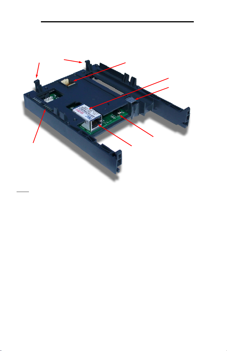
4. Interface Board Overview
Mounting Tabs
LEDs
Drive Connector
MAC ID
Ground Plate
Configuration Switches
Shielded RJ45 Ethernet Jack
Note: The configuration switches are used for factory test only, and should remain in
the OFF (up) position at all times.
13

ICC
5. Installation
This interface card has been designed for quick and simple installation. The card is
connected to the drive's control board via a 30-pin rectangular connector, and is
mechanically supported via an integral housing that seamlessly mates with the
drive’s enclosure. The only tool required for installation is a flat-blade screwdriver.
Before opening the drive, please observe all safety precautions as outlined on the
drive's front cover and in the operation manual.
5.1 Installation Procedure
1. CAUTION! Verify that all input power sources to the drive have
been turned OFF and are locked and tagged out.
2. DANGER! Wait at least 5 minutes for the drive’s electrolytic
capacitors to discharge before proceeding to the next step. Do not touch any
internal parts with power applied to the drive, or for at least 5 minutes
after power to the drive has been removed. A hazard exists temporarily for
electrical shock even if the source power has been removed. Verify that the
CHARGE LED has gone out before continuing the installation process.
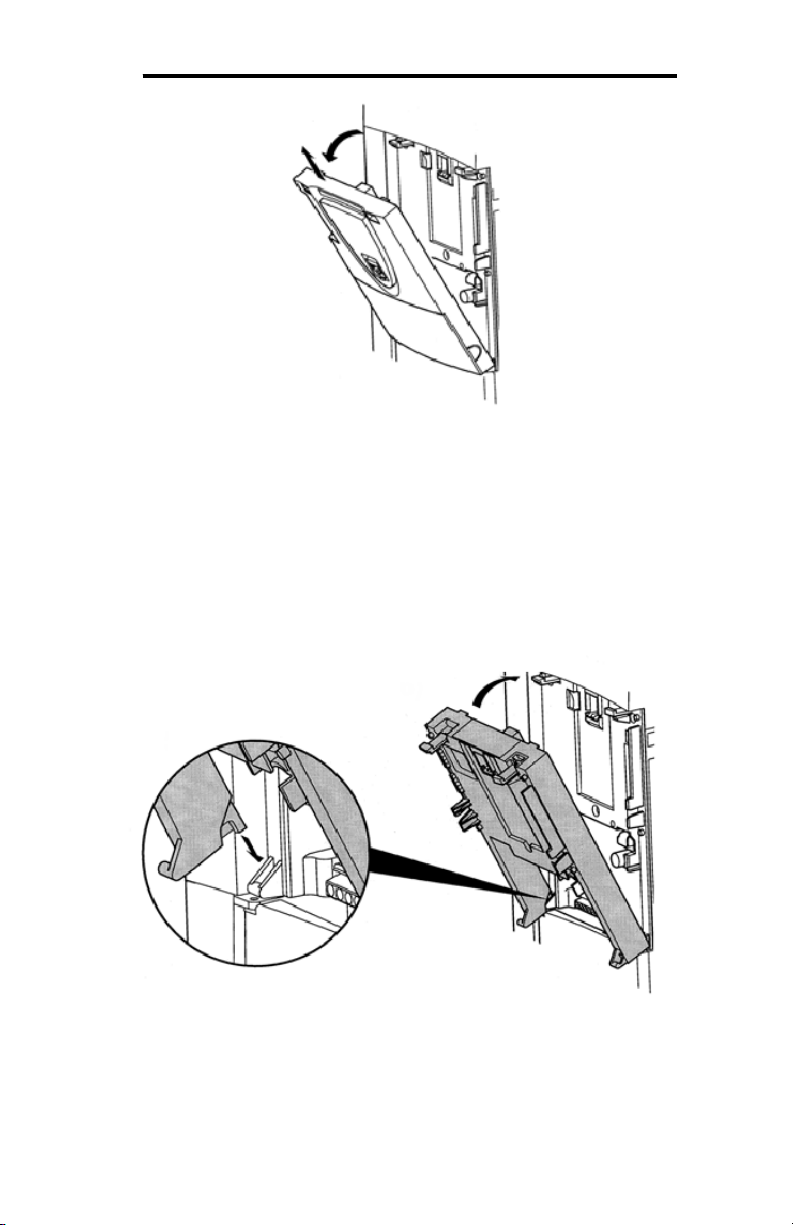
3. Remove the drive’s display panel and front cover by inserting a flat-blade
screwdriver into each of the two mounting tab access openings at the top of the
front cover and depressing each of the mounting tabs (Figure 1). Rotate the top
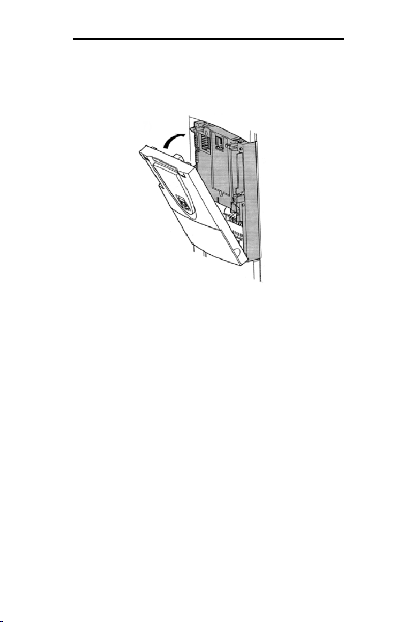
of the font cover outward and remove the cover (Figure 2).
Figure 1: Releasing the Drive's Front Cover
14
ICC
Figure 2: Removing the Drive's Front Cover
4. Install the interface card into the drive by inserting the tabs on the lower legs of
the interface housing into the corresponding slots on the drive’s enclosure.
Rotate the interface housing up and press it onto the drive enclosure’s mounting
tabs, depressing firmly until the housing snaps into place (Figure 3). Doublecheck that the plastic bosses located on the left and right side of the drive
enclosure are properly inserted into the corresponding recesses on the back of
the interface housing, and that the interface housing is overall secure and flush
with the drive enclosure.
Figure 3: Installing the Interface Card
5. Reinstall the drive’s front cover by inserting the tabs on the bottom part of the
front cover into the corresponding slots on the interface housing. Rotate the
front cover up and press it onto the interface housing’s mounting tabs,
15
ICC
depressing firmly until the front cover snaps into place (Figure 4). Double-check
that the plastic bosses located on the left and right side of the interface housing
are properly inserted into the corresponding recesses on the back of the front
cover, and that the front cover is overall secure and flush with the interface
housing.
Figure 4: Reinstalling the Drive's Front Cover
6. Insert the network cable into the Ethernet jack. Ensure that the connector is fully
seated into the jack, and route the cable such that it is located well away from
any electrical noise sources, such as drive’s input power or motor wiring. Also
take care to route the cable away from any sharp edges or positions where it
may be pinched.
7. Turn the power source to the drive ON, and verify that it functions properly. If
the drive does not appear to power up, or does not function properly,
immediately turn power OFF. Repeat steps 1 and 2 to remove all power from
the drive. Then, verify all connections. Contact ICC or your local Toshiba
representative for assistance if the problem persists.
5.2 Installing Multiple Option Cards
When this communication interface is installed into a drive in conjunction with an I/O
option card, the I/O option card must be installed first (adjacent to the drive’s
enclosure), and the communication interface must be installed last (adjacent to the
drive’s front panel).
16
ICC
6. LED Indicators
6.1 Front Panel
The interface board has 5 bicolor (red/green) LEDs that are visible through the
ASD’s front cover (labeled 2.1 through 2.5).
2.2
2.3
Interface Status 2.1
EIP Module Status /
Reserved
EIP Network Status /
PROFINET Cnxn Status
Ethernet Activity 2.4
Heartbeat 2.5
Interface Status: Normally solid
green during operation. If a fatal error
occurs, this LED will flash a red error
code. The number of sequential blinks
(followed by 3s of OFF time) indicates
the error code.
EIP Module Status / Reserved:
When the multi-protocol firmware
image (with EtherNet/IP support) is
loaded, this LED conforms to the
prescribed “module status LED”
behavior as dictated in the
EtherNet/IP specification, Volume 2,
Chapter 9. When the PROFINET IO
firmware image is loaded, this LED is
reserved, and therefore always OFF.
17
ICC
EIP Network Status / PROFINET IO Connection Status: When the multi-protocol
firmware image (with EtherNet/IP support) is loaded, this LED conforms to the
prescribed “network status LED” behavior as dictated in the EtherNet/IP
specification, Volume 2, Chapter 9. When the PROFINET IO firmware image is
loaded, this LED is on solid green when the controller has established a link with the
interface board and is communicating with it.
Ethernet Activity: Blinks green briefly when network packets are sent or received.
Heartbeat: Blinks green to indicate communication between the interface card and
the drive. Contact ICC technical support if a blinking red error code is observed.
6.2 Ethernet Jack
The Ethernet jack also contains two embedded LEDs.
Reserved
Ethernet Link
Ethernet Link: This amber LED is lit whenever a viable Ethernet network is
connected to the port.
Reserved: This green LED is currently unused and is therefore always OFF.
18
ICC
7. Configuring the IP Address
Before you can access the interface from your web browser or begin using it as a
part of your automation network, you must know its IP address. The interface comes
from the factory configured to obtain an IP address dynamically (DHCP/BOOTP).
You can determine the interface’s current IP address using the discovery software
included on the CD provided with the interface, or available from the ICC homepage
at http://www.iccdesigns.com.
7.1 Via the Finder Utility
To configure the interface to use a static IP address:
1. Connect the interface to your network and apply power to the ASD. When the
interface boots up, it will attempt to obtain an IP address from a DHCP server or,
failing that, will fallback to either the last static IP address assigned, or a default
static IP address of 192.168.16.102 if no static IP address has yet been
assigned.
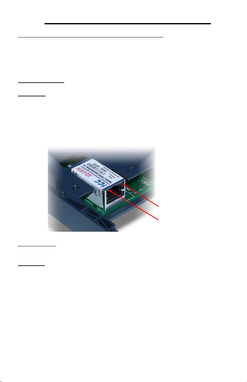
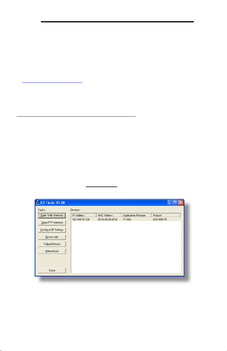
2. To determine the initial IP address of your interface, start the ICC FINDER.EXE
discovery utility.
3. The discovery utility scans the network for ICC devices and then lists each
device’s IP Address, MAC Address, Firmware Version and Product ID.
Identify your device by its MAC address (printed on a label on the top of the
Ethernet network jack). Refer to Figure 5.
Figure 5: ICC Finder Discovery Utility
4. To change the IP address, select the device in the list of detected devices and
click the Configure IP Settings button.
5. In the dialog that appears, select Manually configure network settings.
19

ICC
6. Enter the desired IP Address, Subnet Mask and Default Gateway in the
appropriate boxes, then click Apply.
7. Enter the case-sensitive system password (default is “icc”) in the Authentication
dialog box, then click Submit.
8. A popup dialog box will prompt you to reboot. Click Reboot. Rebooting may
require 30s or more to complete. When the device status indicates “Ready”,
click Close.
9. The discovery utility will automatically rescan the network. Confirm that the new
IP address has been accepted by the device.
7.2 Via the Drive’s Keypad
This section applies to G9 (drive control board firmware V203R5 and later) and H9
(drive control board firmware V204R4) drives only.
The interface card’s IP Address, Subnet Mask, Default Gateway, and DHCP/Static IP
mode can be viewed and modified via the drive’s keypad by navigating to
Program…Communications…Ethernet Settings. Additionally, the interface card’s
unique MAC ID can be viewed (but not modified) in this screen.
Note that these parameter values are read by the interface card only during initial
boot-up. Therefore, be sure to power cycle the drive whenever any of these values
are changed to allow the changes to take effect.
7.3 Via the Web Page
Once an initial IP address has been assigned to the device and the configuration
web page can be accessed, the IP address-related parameters can also be modified
via the web page. Refer to section 10.7.4.
20

ICC
8. Using the ICC Finder Utility
The “ICC Finder” utility is a simple Windows PC program (just a single .exe file, no
installations, DLL’s etc.), which when executed discovers all ICC communication
interfaces on the current Ethernet subnet, regardless of whether or not their network
parameters are currently compatible with the subnet upon which they reside. Refer
to Figure 5 on page 19.
In order for the Finder application to discover devices, certain UDP Ethernet traffic
must be allowed in and out of the computer, and firewall applications (such as
Windows Firewall) are often configured to block such traffic by default. If the Finder
is unable to discover any devices on the current subnet, be sure to check the
computer’s firewall settings during troubleshooting, and add an exception to the
firewall configuration if necessary.
All discovered devices can be organized in ascending or descending order by
clicking on the desired sort header (IP Address, MAC Address, Application Firmware
or Product). The buttons on the left side of the window perform the following actions:
Open Web Interface: Opens a web browser page of the selected device. Refer to
section 10.
Open FTP Interface: Opens the computer’s default FTP application, which could be
either Windows Explorer, a web browser, or a 3rd-party FTP program (whatever the
computer/operating system is configured for by default). This allows you to interact
directly with the unit’s on-board flash filesystem, enabling you to drag and drop files
to/from the unit and upload new firmware. Refer to section 11.
Configure IP Settings: Allows configuration of whether the device will use static IP
parameters or will obtain its IP parameters via DHCP. Refer to section 7 for more
information.
Device Info: Opens a dialog box containing relevant device information.
Reboot Device: Opens a dialog box which prompts for a password to reboot the
interface. Enter the case-sensitive system password (default is “icc”), then click
Reboot. The reboot cycle has completed when the displayed status changes from
“Rebooting” to “Ready” (note that this may require 30s or more to complete.)
Clicking Close will then close the dialog box and cause the discovery utility to
automatically rescan the network.
Refresh List: Causes the discovery utility to rescan the network.
Close: Closes the discovery utility.
21

ICC
9. Parameter Numbering
Inspection of the Toshiba ASD user’s manual reveals that the ASD’s parameters are
organized as hexadecimal numbers ranging from F000 to FFFF. These parameters
are made accessible to the interface board as “registers”, and are numerically
remapped to present a more natural interface to the communications user. There
are 1500 total registers available via the interface board, and their mappings are as
shown in Table 1.
Table 1: ASD Parameter-to-Register Mapping
Hexadecimal ASD
Parameter Numbers…
F000 - F999 1 - 1000
FA00 - FA99 1001 - 1100
FB00 - FB99 1101 - 1200
FC00 - FC99 1201 - 1300
FD00 - FD99 1301 - 1400
FE00 - FE99 1401 - 1500
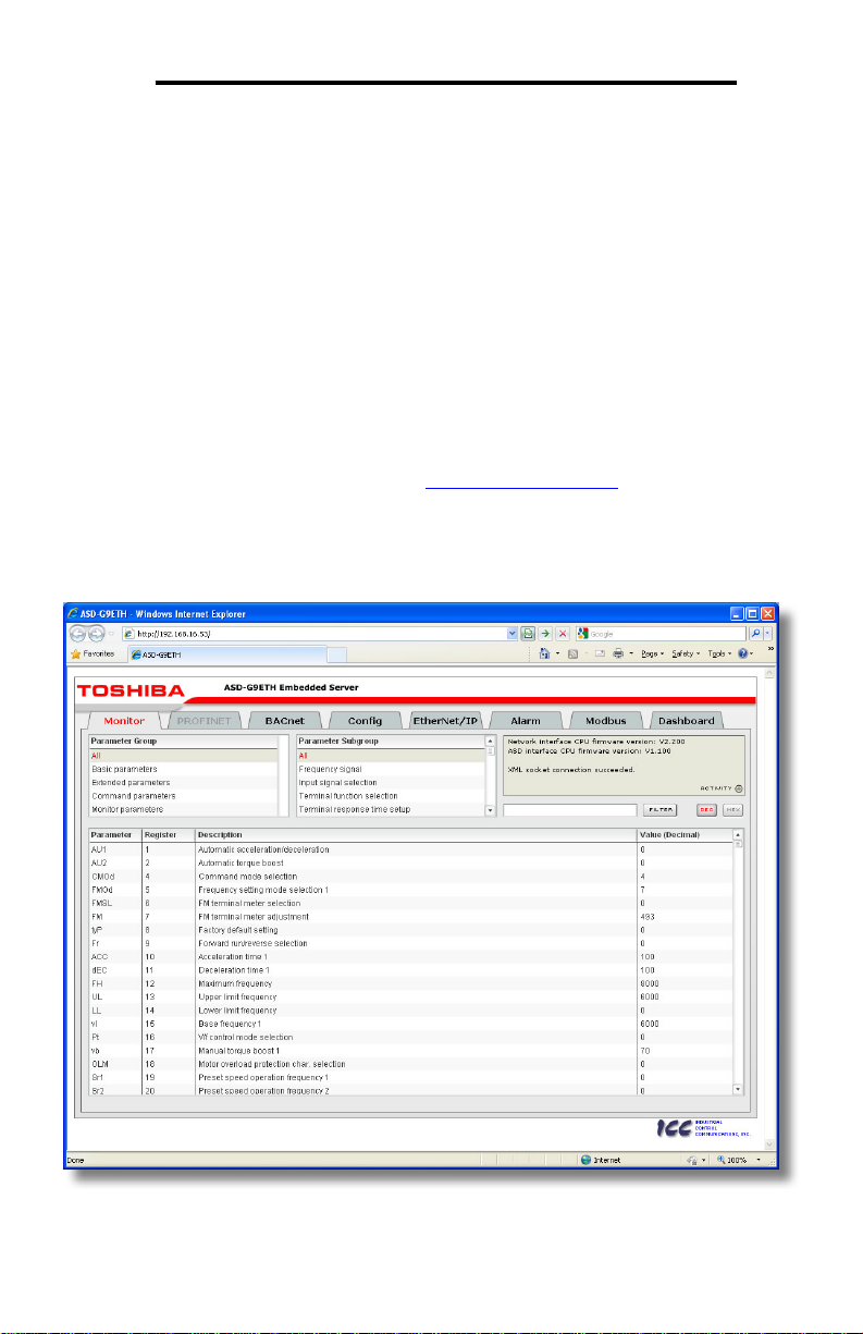
This mapping is easier to understand if one just uses the interface's web page as a
guide (refer to Figure 6 and section 10.4.4). The "parameter” numbers (ASD
references) and "register” numbers (network references) for all available parameters
are shown in the first two columns. Commanding the drive over the network
therefore entails writing to registers 1007 (option board command 1) and 1008
(option board frequency command), which correspond to ASD parameters FA06 and
FA07, respectively.
…Map to Decimal Register
Numbers
Figure 6: Web Page Register Assignment Reference
22

ICC
To avoid confusion, when this user’s manual uses the term “parameter”, it will be
referring to the ASD’s hexadecimal number as documented in the ASD user’s
manual. Similarly, when this user’s manual uses the term “register”, it will be
referring to the decimal number as it is exposed to the network interface.
Note that although 1500 total registers are available in the register space, not all of
those registers have corresponding parameters that exist in the drive. In other
words, if a read from or write to a register that does not correspond to an existing
drive parameter takes place, the read/write will be successful, but the data will have
no meaning. This feature is beneficial in situations where the accessing of noncontiguous registers can be made more efficient by accessing an all-inclusive block
of registers (some of which correspond to drive parameters and some of which do
not), while only manipulating those in your local programming that are known to exist.
For a complete listing of all available drive parameters, their bit mappings, scaling
values etc., please refer to the Toshiba “TOSVERT VF-AS1 Series RS485
Communication Function Instruction Manual” (Toshiba document #E6581315). As a
user convenience, the structure of the commonly-used “option board command 1”
word (drive parameter FA06 / register 1007) is replicated here (refer to Table 2).
Table 2: Structure of "Command 1" Word (Drive Parameter FA06)
23
ICC
10. Embedded Web Server
10.1 Overview
The interface contains an embedded web server (also known as an HTTP server),
which allows users to access the drive’s internal data in a graphical manner with web
browsers such as Microsoft Internet Explorer or Mozilla Firefox. In this way, the drive
can be monitored, configured and controlled from across the room or from across the
globe.
In order to view the interface’s web page, the free Adobe Flash Player browser plugin is required. If the plug-in is not already installed on your computer, then your
browser will automatically be redirected to the appropriate Adobe download web site
when you initially attempt to access the interface’s web page. Alternatively, the plugin can be downloaded directly by going to http://www.adobe.com, and choosing the
“get Adobe Flash Player” link. Always ensure that you have the latest version of the
Flash Player installed: if some aspect of the web page does not appear to be
displayed properly, installing the latest Flash Player update usually resolves the
problem.
Figure 7: Embedded Web Server
24
ICC
To access an interface’s embedded web server, either use the finder utility (refer to
section 8) and select the “Open Web Interface” button when the target unit is
highlighted, or just directly enter the target unit’s IP address into the address (URL)
field of your web browser. Refer to Figure 7 for a representative screenshot of the
web server interface.
In order to access the web server and view the parameter values, destination TCP
ports 80 and 2000 must be accessible from the client computer. If an “XML socket
connection failed” error message is displayed in the information window, and no
parameter values are shown, this is typically indicative of port 2000 being blocked by
a firewall or Ethernet router situated between the client computer and the interface
card.
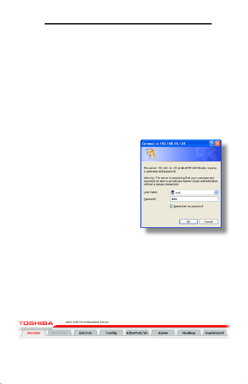
10.2 Authentication
For security, the interface requires valid user
authentication whenever the web page is
accessed. The authentication request will
appear as a browser popup box that will
request entry of a user name and password.
Refer to Figure 8.
The factory-default user name is “root”, and
the password is “icc”. Note that the username
and password are case-sensitive, and that
once authenticated, the authentication will
remain in effect from that point until all browser
windows are closed. The authentication
credentials can also be changed from their
default settings (refer to section 10.7.3.)
10.3 Page Select Tabs
Figure 8: Web Server
Authentication
The web interface is subdivided into several different “tabs” of associated
information, much the same as how folders in a filing cabinet are arranged. Refer to
Figure 9. To change tabs, just click on the tab you wish to view. The title of the
currently-selected tab is red. Note that because different protocols are supported by
the interface with different firmware images, not all tabs may be accessible with the
firmware image currently loaded. The titles of tabs that are not accessible are
grayed-out, and clicking them has no effect.
Figure 9: Page Select Tabs
25
ICC
10.4 Monitor Tab
10.4.1 Information Window
Figure 10 shows the Information
Window, which is located in the upperright hand corner of the monitor tab.
This window displays various
informational messages regarding the
status of the interface card or web
browser session. There is also an
“activity” indicator located in the lowerright hand corner of the Information
Window, which blinks periodically to
show the status of data communication between the web browser and the interface
card. If you do not observe the activity indicator blink at all for several seconds or
more, it is possible that the web browser may have lost contact to the web server due
to a drive reset or a network problem: to reestablish communications, select “refresh”
on your web browser.
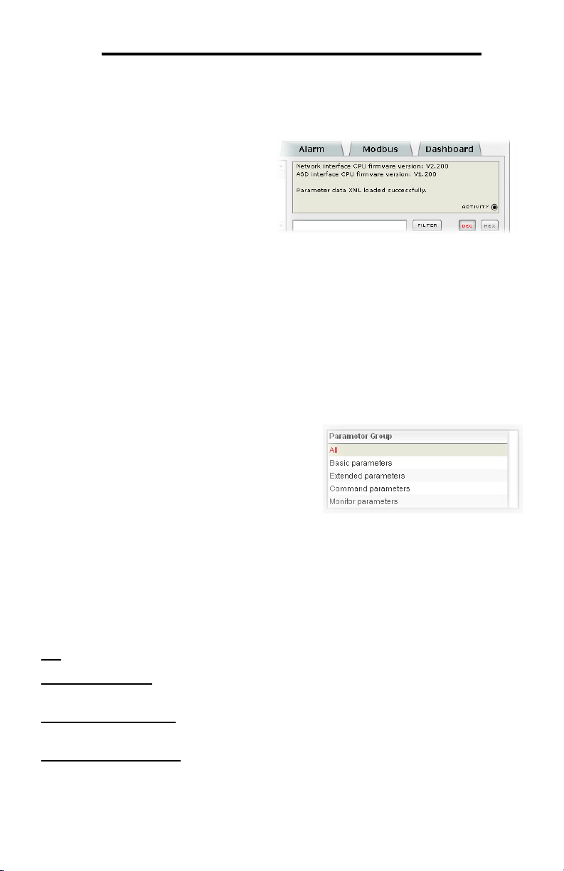
10.4.2 Parameter Group Selection List
Figure 10: Monitor Tab Information
Window
The Parameter Group Selection List is located
in the upper-left hand corner of the Monitor
Tab. Refer to Figure 11. Individual groups can
be selected by clicking on the group name.
Multiple groups may also be selected by
holding down the CTRL key while clicking on
the group names, or a range of groups can be
selected by first selecting the starting group,
and then holding down the SHIFT key while
selecting the last group in the range. When a
parameter group is selected, the parameter subgroups (if any) contained in that
parameter group are displayed in the Parameter Subgroup Selection List (refer to
section 10.4.3), and the corresponding parameters are displayed in the Parameter
List (refer to section 10.4.4). The following parameter groups are available:
All: All parameters are available (configuration, command and monitor parameters).
Basic Parameters: The configuration parameters most commonly used for drive
setup are available.
Extended Parameters: All other configuration parameters that are not “basic
parameters” are available.
Command Parameters: Drive command parameters are available. Note that
although all parameters associated with drive control are available in this selection,
only those parameters that are identified as being for the “internal option board” can
Figure 11: Parameter Group
Selection List
26
ICC
be used to actually control the drive via the option board: all other drive command
parameters can only be monitored via the option board.
Monitor Parameters: Drive monitor parameters are available.
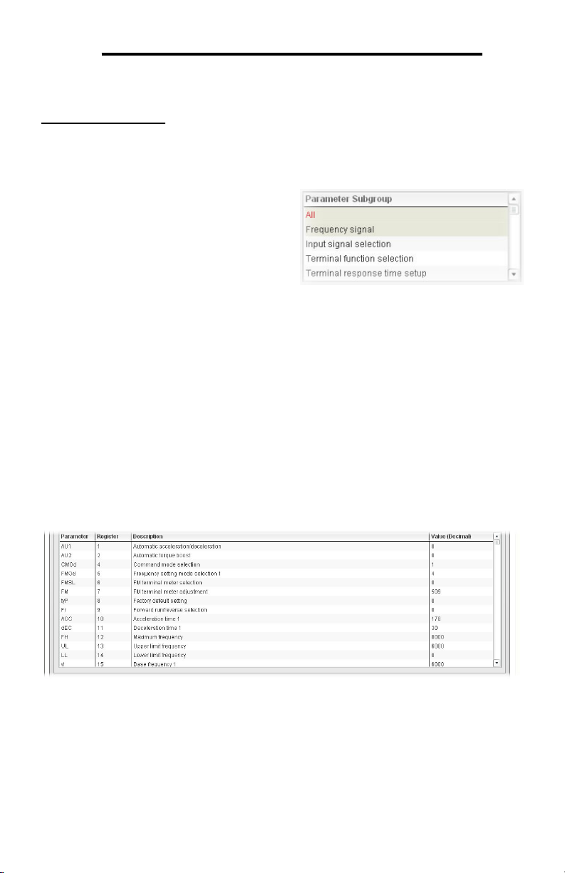
10.4.3 Parameter Subgroup Selection List
Subgroups can be used to further filter the
parameters of a group that are to be
displayed in the Parameter List. Refer to
Figure 12.
If the group currently selected in the
Parameter Group Selection List (refer to
section 10.4.2) has subgroups available,
then choosing one or more desired
subgroups will further filter the parameters
that are displayed in the Parameter List. If the currently-selected group does not
have any available subgroups, then only the “All” subgroup will be shown, and all
parameters in that group will be shown in the Parameter List.
Figure 12: Parameter Subgroup
Selection List
10.4.4 Parameter List
The bottom half of the Monitor tab contains the parameter list (refer to Figure 13).
The parameters that are displayed in the list at any given time depend on the
groups/subgroups selected, as well as whether or not any filters have been applied
(refer to section 10.4.5).
Figure 13: Parameter List
The first two columns of the Parameter List show the parameter name and the
register number that provides access to that parameter, and were discussed in detail
in section 9. The third column contains the parameter descriptions, which are used
by the filter function. The last column performs two functions: it displays the current
27

ICC
value of the parameter, and also allows changing the parameter’s value by clicking
on the number in the value column and entering the new value.
Some items to keep in mind when interacting with the Parameter List are:
• When entering new parameter values, be sure that the number being entered is
appropriate for the currently-selected radix (refer to section 10.4.6): for example,
an entered value of “1000” in hexadecimal is equal to 4096 in decimal.
• If desired, the column widths can be changed by dragging the vertical bars that
separate the header row’s cells to a different position.
• If you begin changing a parameter value and then decide to abandon the
change, pressing the ESC key on your keyboard will abandon the change and
redisplay the current parameter value.
• When editing a parameter value, clicking someplace off the entry cell is
equivalent to hitting the ENTER key.
10.4.5 Parameter List Filter
A filter function provides Parameter List search capabilities. To use the filter
function, simply type a word or portion of a word into the filter entry box and then click
the “filter” button. Refer to Figure 14.
The filter will then display only those
parameters currently available in the
Parameter List that satisfy the search criteria.
For example, to find all monitor parameters
that contain some derivative of the word “volt”
(such as “voltage” or “volts”), select the
“Monitor Parameters” group, the “All”
subgroup, enter “volt” in the filter entry box, and then click the “filter” button.
Once a filter has been entered, it will continue to be applied to all information
normally displayed in the Parameter List for as long as the filter term is left in the
filter entry box. Continuing the previous example where we filtered on the root term
“volt” in the monitor parameters, we can then easily apply this filter to all parameters
(configuration, command or monitor) simply by selecting the “All” parameter group.
The Parameter List will now display all configuration, command or monitor
parameters that contain the root term “volt”.
To remove the filter, delete any characters contained in the filter entry box and then
click the “filter” button.
Figure 14: Parameter List Filter
28

ICC
10.4.6 Radix Selection
Figure 15 shows the radix selection buttons.
These selection buttons allow changing the
Parameter List “value” column data display and
entry radix between decimal and hexadecimal
formats.
When “DEC” is selected, the “value” column heading will be “Value (Decimal)”,
current parameter values will be displayed in decimal, and values to be written to
parameters must be entered in decimal format. For example, to change the drive’s
frequency command to 40.00Hz, enter the decimal value 4000.
Similarly, when “HEX” is selected, the “value” column heading will be “Value
(Hexadecimal)”, current parameter values will be displayed in hexadecimal, and
values to be written to parameters must be entered in hexadecimal format. For
example, to turn on bits #15, #14 and #10 in the drive’s “command 1” word, enter the
hexadecimal number C400.
Figure 15: Radix Selection
29
 Loading...