


No. 2B771-004EN*M
OPERATION MANUAL
FOR
DIAGNOSTIC ULTRASOUND SYSTEM
MODEL TUS-A500
[FUNDAMENTALS] (2B771-004EN*M)
CAUTION:
In the USA, federal law restricts this device to sale by or on the order of a physician.
IMPORTANT!
Read and understand this manual before operating the equipment. After reading, keep this manual in an easily accessible place.
TOSHIBA MEDICAL SYSTEMS CORPORATION 2010-2014
ALL RIGHTS RESERVED

Introduction
This operation manual describes the operating procedures for the diagnostic ultrasound system TUS-A500. To ensure safe and correct operation of the system, carefully read and understand the manual before operating the system.
Trademarks
Windows® is a registered trademark of Microsoft Corporation in the United States and other countries.
Clorox Healthcare is a trademark of The Clorox Company. Dispatch® is a registered trademark of The Clorox Company. Cleanisept® is a registered trademark of Dr. Schumacher GmbH. Java is a registered trademark of Oracle and/or its affiliates.
APLIO, Dynamic Flow, ApliPure, MicroPure, and TwinView are trademarks of Toshiba Medical Systems Corporation.
This manual may include trademarks or registered trademarks of other companies.
Note that the trademark symbol " " and the registered trademark symbol " " may or may not be used in this manual.
IMPORTANT!
1.No part of this manual may be copied or reprinted, in whole or in part, without prior written permission.
2.The contents of this manual are subject to change without prior notice and without legal obligation.
3.The contents of this manual are correct to the best of our knowledge. Please inform us of any ambiguous or erroneous descriptions, missing information, etc.
No. 2B771-004EN*M

Organization of the Operation
Manuals
1.Notation Conventions
In this operation manual, the following word is used in addition to the signal words related to the safety precautions (refer to section 2 "General Safety Information"). Please read this operation manual before using the system.
NOTE: Indicates reference information that enables more efficient use of the equipment.
2.Operation Manuals
A TOSHIBA service person or instructor will explain the basic operating procedures for this system at the time of delivery. However, read this operation manual carefully before using the system in order to understand the detailed operating procedures, functions, performance, and maintenance procedures.
Operation manual for the main unit of the ultrasound system
Fundamentals volume (this manual)
.........Describes the basic information concerning the system, such as preparation for examination, operation, inspection, and functional descriptions of the system.
|
Applications volume |
|
.........Describes the exam data manipulation |
|
|
|
procedures and optional unit operation |
||
|
|
|
||
|
|
|
||
|
|
|
procedures. |
|
|
|
|
.........Describes the registration and |
|
|
Measurements volume |
|
||
|
|
measurement procedures. |
||
|
|
|
||
|
|
|
||
|
|
|
.........Describes the acoustic power |
|
|
Acoustic power and surface |
|
||
|
|
transmitted from the ultrasound |
||
|
temperature data |
|
||
|
|
transducer. |
||
|
|
|
||
|
|
|
||
|
|
.....................Describes the operating and |
||
Operation manual for each |
||||
|
disinfection/sterilization procedures for |
|||
transducer |
|
|||
|
the transducer. |
|||
|
|
|
||
|
|
|
||
NOTE: For certain applications, the following manuals are available in English:
2B771-005EN Applications volume
2B771-006EN Measurements volume
2B771-007EN Acoustic power and surface temperature data (For regions other than the USA)
2B771-008EN Acoustic power and surface temperature data (For the USA only)
2B771-010EN Operation card
NOTE: The operation manuals Applications volume and Measurements volume may be supplied on electronic media.
No. 2B771-004EN*M
U-1
3. |
Switch Configuration |
|
|
The descriptions in this operation manual are based on the standard switch configuration. If |
|
|
the switch configuration has been changed, the differences between the current configuration |
|
|
and the standard configuration must be understood before use. |
|
|
The layout, shapes, labels, and icons of the switches on the touch panel can be changed. All |
|
|
the figures of touch panel and switches in this manual are examples and may differ from the |
|
|
actual display. |
|
4. |
Operation Switches |
|
Some operations can be performed using either the switches on the main panel or the corresponding switches on the touch panel.
The switches displayed on the touch panel differ depending on the selected exam type, transducer, and mode.
No. 2B771-004EN*M
U-2 |
* |
Table of Contents
Organization of the Operation Manuals...................................................... |
U-1 |
1. |
Intended Use..................................................................................... |
1-1 |
1.1 |
Intended Medical Use .......................................................................... |
1-1 |
1.2 |
Intended Patient Information.......................................................... |
1-1 |
1.3 |
User Profile.................................................................................................. |
1-1 |
1.4 |
Operating Principles............................................................................. |
1-1 |
2. |
General Safety Information........................................... |
2-1 |
2.1 |
Meaning of Signal Words.................................................................. |
2-1 |
2.2 |
Meaning of Safety Symbols ............................................................ |
2-1 |
2.3 |
Ensuring the Safety of Patients and Operators................ |
2-2 |
2.4Preventing Electric Shocks, Fires, and
|
Power Supply Interruptions ............................................................ |
2-3 |
2.5 |
Chemical Hazard ..................................................................................... |
2-5 |
2.6 |
Electromagnetic Compatibility (EMC)...................................... |
2-5 |
2.7 |
Acoustic Power........................................................................................ |
2-6 |
2.8 |
Preventing System Malfunctions ................................................ |
2-7 |
2.9 |
Handling Patient and Image Data................................................ |
2-9 |
2.10 |
Warning Labels ........................................................................................ |
2-9 |
2.11 |
Regulatory Labels ................................................................................ |
2-12 |
2.12Precautions Concerning Clinical
Examination Techniques................................................................. |
2-13 |
No. 2B771-004EN*M
- a -
3.General Information on Usage and
|
Maintenance....................................................................................... |
3-1 |
4. |
Use Conditions .............................................................................. |
4-1 |
4.1 |
Power and Environmental Requirements ............................. |
4-1 |
4.2Environmentally Friendly Usage and
|
Maintenance Management ............................................................... |
4-2 |
5. |
System Configuration........................................................... |
5-1 |
5.1 |
Standard Configuration...................................................................... |
5-1 |
5.2 |
List of Optional Units........................................................................... |
5-1 |
5.3 |
Compatible Peripheral Devices.................................................... |
5-2 |
5.4 |
External Storage Devices ................................................................. |
5-2 |
5.5 |
List of Optional Software .................................................................. |
5-3 |
5.6 |
List of Available Transducers........................................................ |
5-4 |
6. |
Names and Functions of Each Section ........ |
6-1 |
6.1 |
Name of Each Section......................................................................... |
6-1 |
6.2 |
Main Panel ................................................................................................... |
6-3 |
6.3 |
Rear Panel.................................................................................................... |
6-7 |
6.4 |
Symbols......................................................................................................... |
6-8 |
7. |
Preparation for Examination....................................... |
7-1 |
7.1 |
Moving and Installing the System .............................................. |
7-1 |
7.2Handling and Connecting/Disconnecting the
|
Transducer .................................................................................................. |
7-4 |
7.2.1 |
Handling the transducer ............................................................................ |
7-4 |
No. 2B771-004EN*M
- b -
7.2.2 |
Connecting/Disconnecting the transducer |
........................................ 7-4 |
7.3 |
Adjusting the Main Panel.................................................................. |
7-6 |
7.4 |
Adjusting the Monitor.......................................................................... |
7-8 |
7.4.1 |
Locking and releasing the monitor ....................................................... |
7-8 |
7.4.2 |
Adjusting the angle of the monitor........................................................ |
7-9 |
7.4.3 |
Adjusting the monitor display............................................................... |
7-10 |
8. |
Checks Before and After Use..................................... |
8-1 |
8.1 |
Checks Before Turning ON the Power .................................... |
8-1 |
8.2 |
Checks After Turning ON the Power ........................................ |
8-2 |
9. |
Turning the Power ON/OFF........................................... |
9-1 |
9.1Connecting the Power Cable and the
|
Protective Grounding .......................................................................... |
9-2 |
9.2 |
Turning ON the Power......................................................................... |
9-4 |
9.3 |
Turning the Power OFF ...................................................................... |
9-6 |
9.4 |
Standby Mode ........................................................................................... |
9-9 |
9.4.1 |
Setting Standby mode ................................................................................ |
9-9 |
9.4.2 |
Recovery from the Standby status...................................................... |
9-11 |
9.5Preparation for Use During Surgery or for
|
Emergency Cases ................................................................................ |
9-12 |
9.5.1 |
Preparation of a backup system........................................................... |
9-12 |
9.5.2 |
Power OFF/ON in the case of system failure................................... |
9-12 |
10. |
Basic Screen and Menu................................................... |
10-1 |
10.1 |
Display of Various Data Items ..................................................... |
10-1 |
10.2 |
Displaying the Acoustic Power Data...................................... |
10-2 |
No. 2B771-004EN*M
- c -
10.3 |
Thumbnail Display............................................................................... |
10-4 |
11. |
Starting an Examination.................................................. |
11-1 |
11.1Entering and Saving Data on the
|
[Patient Registration] Screen....................................................... |
11-2 |
12. |
Reference Signal Display............................................... |
12-1 |
12.1 |
Reference Signal Panel .................................................................... |
12-4 |
12.2 |
Installing the Reference Signal Sensor ................................ |
12-5 |
12.3 |
Adjusting Reference Signals........................................................ |
12-5 |
13. |
Common Operation for Each Mode................. |
13-1 |
13.1 |
Touch Panel Operation..................................................................... |
13-1 |
13.2 |
Trackball Functions ............................................................................ |
13-8 |
13.2.1 |
Trackball function area............................................................................. |
13-8 |
13.2.2 |
Trackball operations.................................................................................. |
13-9 |
13.3 |
Selecting an Imaging Preset During Examination...... |
13-10 |
13.3.1 |
[DEFAULT PRESET] tab......................................................................... |
13-12 |
13.3.2 |
[USER PRESET] tab................................................................................. |
13-15 |
13.3.3 |
[Sub Preset] menu.................................................................................... |
13-15 |
13.4Selecting an Application Preset
During Examination .......................................................................... |
13-16 |
13.5Changing the Transducer During
|
Examination............................................................................................ |
13-18 |
14. |
Display and Operation in Each Mode............ |
14-1 |
14.1 |
2D Mode....................................................................................................... |
14-1 |
14.1.1 |
2D display layout ........................................................................................ |
14-1 |
No. 2B771-004EN*M
- d -
14.1.2 |
Adjustment using the main panel ........................................................ |
14-2 |
14.1.3 |
Adjustments using the touch panel.................................................... |
14-5 |
14.1.4 |
Selection of image zooming method .................................................. |
14-8 |
14.1.5 |
2D mode quick scan ................................................................................ |
14-10 |
14.1.6 |
Trapezoid scan .......................................................................................... |
14-12 |
14.2 |
M Mode....................................................................................................... |
14-13 |
14.2.1 |
M display layout ........................................................................................ |
14-13 |
14.2.2 |
Adjustment using the main panel ...................................................... |
14-14 |
14.2.3 |
Adjustment using the touch panel .................................................... |
14-16 |
14.2.4 |
FLEX-M mode ............................................................................................. |
14-18 |
14.3 |
CDI Mode................................................................................................... |
14-20 |
14.3.1 |
CDI display layout .................................................................................... |
14-20 |
14.3.2 |
Adjustment using the main panel ...................................................... |
14-21 |
14.3.3 |
Adjustment using the touch panel .................................................... |
14-23 |
14.4 |
Power Angio Mode (Power Mode) .......................................... |
14-25 |
14.4.1 |
Power Angio display layout.................................................................. |
14-25 |
14.4.2 |
Adjustment using the main panel ...................................................... |
14-25 |
14.4.3 |
Adjustment using the touch panel .................................................... |
14-26 |
14.5 |
Dynamic Flow Mode (ADF Mode)............................................ |
14-28 |
14.5.1 |
Dynamic Flow display layout............................................................... |
14-28 |
14.5.2 |
Adjustment using the main panel ...................................................... |
14-28 |
14.5.3 |
Adjustment using the touch panel .................................................... |
14-29 |
14.6 |
TDI Mode (Tissue Doppler Imaging Mode)....................... |
14-31 |
14.6.1 |
TDI display layout..................................................................................... |
14-31 |
14.6.2 |
Adjustment using the main panel ...................................................... |
14-31 |
14.6.3 |
Adjustment using the touch panel .................................................... |
14-32 |
No. 2B771-004EN*M
- e -
14.7 |
Doppler Mode ........................................................................................ |
14-34 |
14.7.1 |
Doppler display layout............................................................................ |
14-34 |
14.7.2 |
Adjustment using the main panel ...................................................... |
14-35 |
14.7.3 |
Adjustments using the touch panel.................................................. |
14-38 |
15. |
Cine Function................................................................................. |
15-1 |
15.1 |
Overview ..................................................................................................... |
15-1 |
15.2 |
Cine Operations..................................................................................... |
15-1 |
16. |
Body Mark........................................................................................... |
16-1 |
16.1 |
Body Mark Entry Mode ..................................................................... |
16-1 |
16.2 |
Setting and Editing Body Marks ................................................ |
16-2 |
17. |
Entering Comments .............................................................. |
17-1 |
17.1 |
Entering Comment Entry Mode.................................................. |
17-1 |
17.2 |
Entering/Editing Characters and Arrow Marks ............... |
17-1 |
18. |
Needle Mark...................................................................................... |
18-1 |
18.1 |
Applicable Transducers and Biopsy Adapters ............... |
18-3 |
18.2Needle Mark Display and Angle Change
|
Procedures................................................................................................ |
18-5 |
18.2.1 |
Needle mark display .................................................................................. |
18-6 |
18.2.2 |
Needle mark angle change procedures............................................. |
18-8 |
19. |
Storing Image Data................................................................. |
19-1 |
19.1 |
Storing Still Images............................................................................. |
19-1 |
19.1.1 |
Operations using the touch panel ....................................................... |
19-1 |
19.2 |
Storing a Dynamic Image................................................................ |
19-2 |
No. 2B771-004EN*M
- f -
19.2.1 |
Operations using the touch panel ....................................................... |
19-3 |
19.2.2 |
Snapshot Clips ............................................................................................ |
19-4 |
19.2.3 |
Cine Clips (storage of cine image data) ............................................ |
19-6 |
19.2.4 |
Setting of the storage format (for retrospective storage) .......... |
19-8 |
19.3 |
File Handling for Image Data........................................................ |
19-8 |
19.4 |
Displaying Saved Images ............................................................... |
19-8 |
20. |
Maintenance..................................................................................... |
20-1 |
20.1 |
Technical Descriptions..................................................................... |
20-1 |
20.2 |
Outline of Preventive Maintenance.......................................... |
20-1 |
20.3 |
Preventive Maintenance Performed by the User ........... |
20-2 |
20.3.1 |
Cleaning the system.................................................................................. |
20-2 |
20.3.2 |
Disinfecting the system ........................................................................... |
20-8 |
20.3.3 |
Creating a backup copy of the system hard disk........................ |
20-10 |
20.3.4 |
[Maintenance] menu ................................................................................ |
20-10 |
20.3.5 |
Backing up the customer-specific data (Backup) ....................... |
20-11 |
20.4Preventive Maintenance Performed by
Service Personnel .............................................................................. |
20-14 |
20.5Periodically Replaced Parts and
|
Consumable Parts.............................................................................. |
20-14 |
20.6 |
Checks During Storage .................................................................. |
20-14 |
21. |
Disposal................................................................................................. |
21-1 |
22.Checks Before the System
Is Judged Defective............................................................... |
22-1 |
23. Specifications................................................................................ |
23-1 |
No. 2B771-004EN*M
- g -
23.1 |
External Dimensions and Mass.................................................. |
23-1 |
23.2 |
Essential Performance of This System................................. |
23-1 |
23.3 |
Conformance Standards ................................................................. |
23-2 |
23.4 |
Safety Classification........................................................................... |
23-3 |
23.5 |
Accuracy of Measurement ............................................................. |
23-4 |
24. |
Using MI/TI......................................................................................... |
24-1 |
24.1 |
Using MI/TI (Outside the USA and Canada)....................... |
24-1 |
24.1.1 |
Basic knowledge of MI/TI......................................................................... |
24-1 |
24.1.2 |
MI/TI display description.......................................................................... |
24-3 |
24.1.3 |
Parameters affecting the MI/TI values................................................ |
24-4 |
24.1.4 |
Operating procedures for MI/TI............................................................. |
24-5 |
24.1.5 |
Output display.............................................................................................. |
24-6 |
24.1.6 |
Reminder........................................................................................................ |
24-6 |
24.1.7 |
Ultrasonic output power and acoustic output ................................ |
24-7 |
24.1.8 |
References for MI/TI................................................................................... |
24-8 |
24.2 |
Using MI/TI (in the USA and Canada)..................................... |
24-9 |
24.2.1 |
Basic knowledge of MI/TI......................................................................... |
24-9 |
24.2.2 |
MI/TI display description........................................................................ |
24-11 |
24.2.3 |
Parameters affecting the MI/TI values.............................................. |
24-12 |
24.2.4 |
Operating procedures for MI/TI........................................................... |
24-13 |
24.2.5 |
Output display............................................................................................ |
24-14 |
24.2.6 |
Information contained in the system documentation................ |
24-15 |
24.2.7 |
Measurement uncertainty and precision ........................................ |
24-15 |
24.2.8 |
Reminder...................................................................................................... |
24-15 |
24.2.9 |
Ultrasonic output power and acoustic output .............................. |
24-16 |
No. 2B771-004EN*M
- h -
24.2.10 References for MI/TI................................................................................. |
24-18 |
25.Guidance and Manufacturer's
|
Declaration......................................................................................... |
25-1 |
26. |
Intellectual Property.............................................................. |
26-1 |
26.1Availability of This Software and
|
Related Documents Is Restricted............................................. |
26-1 |
26.2 |
Agreement for Microsoft Software........................................... |
26-1 |
26.3 |
Others............................................................................................................ |
26-9 |
27. |
Indication of Year of Manufacture...................... |
27-1 |
No. 2B771-004EN*M
- i - |
* |
1. Intended Use
1.1Intended Medical Use
(1)The intended use of this system is to visualize structures, characteristics, and dynamic processes within the human body using ultrasound and to provide image information for diagnosis.
(2)This system provides high-quality ultrasound images in all its modes: 4D mode, 2D mode, M mode, CDI (Color Doppler Imaging) mode (blood-flow imaging), and Doppler mode (blood-flow spectrum).
(3)This system is a general-purpose diagnostic ultrasound imaging system that conforms to the standard for Real Time Display of Thermal and Mechanical Output Indices on Diagnostic Ultrasound Equipment (American Institute of Ultrasound in Medicine (AIUM), 1992). Note that transducers have their own characteristic applications. For the transducers that can be used with this system and their applications, refer to subsection 5.6 "List of Available Transducers".
1.2Intended Patient Information
Age, health condition: Not specified
However, do not use this system if it is judged that the patient will be exposed to hazard due to the patient's own condition.
1.3User Profile
Only physicians or legally qualified persons who have received appropriate training
Before using this system, it must be ensured that the user has received sufficient training.
1.4Operating Principles
This system transmits ultrasound signals into the human body from a transducer and receives the reflected echoes from the human body using the same transducer. It then processes the received signals and displays them as images on a display screen (LCD monitor).
Gating signals are sent from the scan control circuit through the transmission delay circuit and are input to the reception circuit. The reception circuit then generates the transmission signals (electrical pulses) according to the gating signals.
These electrical pulses are applied to piezoelectric elements that convert the electrical signals into mechanical vibrations in the transducer. These mechanical vibrations, which are ultrasound signals, are then transmitted into the human body.
This system supports convex, sector, linear, and some other scanning techniques.
When the ultrasound signals transmitted into the human body encounter a substance with different acoustic characteristics, they are reflected and return to the transducer as echoes. Based on the time required for the ultrasound signals to return to the transducer, the distance between the transducer surface and the reflecting substance can be determined.
No. 2B771-004EN*M
1-1
In 2D (B) mode imaging, the echo amplitudes are represented as brightness changes on the image display screen. Since the ultrasound beam attenuates in tissue, the degree of amplification required generally increases as depth increases. Regions of high reflection are displayed as brighter, while regions of low reflection appear darker.
An M-mode image (cross-sectional image) can be displayed together with a 2D-mode image on the same screen through time-sharing control, allowing the user to perform M-mode diagnosis while observing a 2D-mode image.
In color Doppler imaging, phase detection is performed in a receive signal processing circuit to obtain I and Q signals. These signals undergo frequency analysis with the correlational method in a color Doppler imaging circuit to produce the mean velocity, variance, and power information of the blood flow. These information items are assigned color signals and represented as real-time two-dimensional color Doppler images.
In Doppler imaging, the signals output from the receive signal processing board are frequency-analyzed by fast Fourier transform (FFT) in a Doppler circuit to produce velocity and power information. A Doppler image is then displayed, plotting velocity on the vertical axis, time on the horizontal axis, and representing power as brightness.
This system supports basic measurements including distance, time, angle, and trace, as well as combinations of some basic measurements. In addition, calculations based on the measurement values can be performed for each region (circulatory organ, OB, etc.) using widely accepted expressions. The calculation results can be displayed in values, tables, or graphs.
No. 2B771-004EN*M
1-2 |
* |

2. General Safety Information
This section describes the general precautions and details that must be observed when using this system. Precautions related to specific operations are described in the corresponding sections.
When using the system, be sure to also read the precautions in the operation manual Measurements volume and the operation manual Applications volume, respectively.
2.1Meaning of Signal Words
In this operation manual, the signal words DANGER, WARNING, and CAUTION are used regarding safety and other important instructions. The signal words and their meanings are defined as follows. Please understand their meanings clearly before reading this manual.
Signal word |
Meaning |
|
|
DANGER |
Indicates an imminently hazardous situation which, if not |
|
avoided, will result in death or serious injury. |
WARNING |
Indicates a potentially hazardous situation which, if not |
|
avoided, could result in death or serious injury. |
CAUTION |
Indicates a potentially hazardous situation which, if not |
|
avoided, may result in minor or moderate injury. |
CAUTION |
Indicates a potentially hazardous situation which, if not |
|
avoided, may result in property damage. |
|
|
2.2Meaning of Safety Symbols
Symbol |
Description |
|
|
|
Type-B applied part |
|
* Type B when Type-B applied parts are connected. |
|
The heart sound sensor and pulse wave sensor that can |
|
be connected to this system are Type-B applied parts. |
|
|
|
Type-BF applied part |
|
* Type BF when Type-BF applied part is connected. |
|
The reference signal cables that can be connected to this |
|
system are Type-BF applied parts. |
|
"Attention" (Refer to the operation manual.) |
|
|
No. 2B771-004EN*M
2-1

2.3Ensuring the Safety of Patients and Operators
Observe the following safety precautions to ensure the safety of patients and operators.
 DANGER: This system must be used only when the potential benefits to
the patient are judged outweigh the possible risk to the patient.
 WARNING: 1. Do not use damaged or defective transducers. Doing so may result in injury to the patient.
2.Take special precautions when examining a patient with high temperature. A high patient temperature may slow down cooling of the transducer surface, which may result in a burn injury to the patient.
If the surface temperature of the transducer becomes abnormally high, stop using the transducer and contact your TOSHIBA service representative.
3.This device is contraindicated for ophthalmic use or any application that causes the acoustic beam to pass through the eye.
4.Do not look inside the DVD/CD unit. The emitted laser beam is hazardous to the eyes and other parts of the body.
5.Prolonged and repeated use of keyboards can result in hand or arm nerve disorders in some individuals. Observe the local institutional work safety/health regulations on keyboard use.
6.Do not use the Fusion function (option) for patients who use electronic life-support devices (for example, a cardiac pacemaker or defibrillator). The magnetic field generated in Fusion mode may affect such devices.
 CAUTION: 1. Do not use the transducer on the same region of the patient for a prolonged period. Low temperature burns may occur. Use the transducer for the minimum period of time that is required for diagnosis. Though the transducer surface temperature may exceed the patient's body temperature under some ambient conditions and usage modes, the use of the transducer for normal ultrasound diagnosis is unlikely to cause low temperature burns.
2.Do not sit on the system. Doing so may result in the system moving unexpectedly, causing you to lose your balance and fall.
3.When this system is used to examine an elderly patient or an infant, an attendant should be present if required.
No. 2B771-004EN*M
2-2

2.4Preventing Electric Shocks, Fires, and Power Supply Interruptions
Observe the following safety precautions to prevent electric shocks, fires, and power supply interruptions.
 DANGER: Never use flammable or explosive gases near this system.
Also do not use the system with oxygen or in an oxygenenriched atmosphere. Doing so may result in an explosion (the system is not explosion-proof).
 WARNING: 1. Follow the instructions below regarding the power cable and plug.
Insert the power plug only into a 3-pin (with protective grounding) medical electrical outlet.
Do not connect the power cable to a 2-pin outlet using an adapter.
Do not forcibly bend the cable.
Do not modify the power cable or plug.
Do not damage the power cable or plug.
Do not twist the power cable or plug.
Do not bundle the power cable or plug.
Do not place heavy objects on the power cable or plug.
Do not pinch the power cable or plug.
Do not subject the power cable or plug to impact.
Do not pull the power cable to disconnect the plug from the outlet.
2.If any abnormalities (such as damage or wear) are found on the power cable or plug, the power cable and plug must be replaced. Stop using it immediately and contact your Toshiba service representative. Continuing to use the system may result in electric shock, fire, or interruption of power supply.
3.Do not use the system if the connection to the outlet is loose.
4.If an abnormal smell or noise, or smoke occurs, immediately turn the main power switch on the power panel OFF and disconnect the plug from the power outlet. Continuing to use the system with such an abnormality may result in a fire etc. When using the system, ensure that there is enough space for access to the main power switch.
5.Do not allow this system or other equipment to come into contact with the patient. If this system or other equipment is defective, the patient may receive an electric shock.
No. 2B771-004EN*M
2-3

 WARNING: 6. Do not connect any devices other than those specified by
TOSHIBA to the USB connector or other connectors on the system.
7.Do not connect to the system transducers other than those specified by TOSHIBA, to prevent accidents such as fire.
8.Do not use a defective transducer.
9.Do not remove the covers or panels of the system. Doing so exposes high-voltage parts.
10.When in the patient environment, the operator must not touch any exposed connectors. In addition, if the system covers have been removed for some reason, the operator must be extremely careful not to touch any part where the voltage exceeds 25 VAC or 60 VDC and the patient at the same time. Doing so may result in an electric shock.
11.Connect the equipotential terminal ( ) of this system to the equipotential bus of the facility using an equipotential conductor. When this system is used close to a device that is applied directly to the patient heart (such as in a cardiac catheterization room, CCU, or ICU), voltage equalization with the device is required to prevent an electric shock to the patient.
12.A functional ground terminal (  ) is used to connect a functional grounding wire between systems or between the system and the ground for functional purposes of the system (for example, to eliminate potential differences in the signal level between systems or to eliminate potential differences between the system and the ground). Do not use the functional ground terminal for protective grounding. Also, do not connect the functional ground terminal to a gas pipe or water pipe. Doing so may result in the failure of functional grounding or in a gas explosion.
13.Use a separate socket with an appropriate rated capacity for the supply of power to this system.
14.Do not connect this system to an outlet that shares a circuit breaker (or fuse) with an outlet to which a device such as a life-support system is connected. If this system malfunctions and generates an overcurrent, or if there is a current surge when the power is turned ON, the circuit breaker may trip (or the fuse may blow).
15.Do not connect the diagnostic ultrasound system to the same power outlet as another device. Doing so may cause the circuit breaker of the facility to trip, fuses to blow, or a fire or electric shock to occur.
No. 2B771-004EN*M
2-4

 WARNING: 16. Remove the ECG electrodes from the patient before using
devices such as electric scalpels, high-frequency therapy equipment, electrostimulators, or electric defibrillators. In addition, when using such devices, do not let ultrasound transducers, PCG microphones, or pulse wave sensors to come into contact with the patient. Doing so may result in the patient receiving a burn injury or an electric shock.
 CAUTION: 1. To prevent electric shock, do not connect peripheral units (such as a video printer or video recording unit) to an external outlet. Peripheral units should be connected inside the system. For the connection procedures, contact your TOSHIBA service representative.
2.If any abnormality of the system is found as a result of inspection, stop using the system and contact your TOSHIBA service representative for repair.
3.Do not spill or spray liquids such as water onto the system or peripheral units.
2.5Chemical Hazard
Observe the following instruction in order to protect patients and operators from inflammation or poisoning by chemical substances.
 WARNING: Handling the cord on this product will expose you to lead, a
chemical known to the State of California to cause birth defects or other reproductive harm.
Wash hands after handling.
2.6Electromagnetic Compatibility (EMC)
Definition: Electromagnetic compatibility (EMC) refers to the ability to function without causing electromagnetic interference (EMI) in other devices or systems, as well as to a certain level of immunity to EMI from other devices or systems.
Observe the following precautions to ensure EMC.
 WARNING: The use of transducers and cables other than those
specified, with the exception of transducers and cables sold by Toshiba Medical Systems Corporation as replacement parts, may result in increased emissions or reduced system performance.
No. 2B771-004EN*M
2-5
 CAUTION: Malfunctions due to radio waves
(1)This system may malfunction due to electromagnetic influence from electric scalpels, high-frequency therapy equipment, or other devices that generate high frequencies.
(2)The use of radio-wave-emitting devices near this unit may interfere with its operation. Devices that generate radio waves, such as cellular phones, transceivers, and radiocontrolled toys, must not be brought into the room where this unit is installed and must never be used near the unit.
(3)If a device that generates radio waves is brought into the room where this unit is installed, instruct the user to turn OFF the power of the device immediately. This is necessary to ensure proper operation of the system.
CAUTION: 1. Do not use this system in locations exposed to strong electric or magnetic fields (near transformers, for example). Such fields may adversely affect the monitor.
2.Do not use this system near devices that generate high frequencies (such as medical telemeters and cordless telephones). Doing so may cause the system to malfunction or to adversely affect such devices.
3.Do not use devices that generate high frequencies near other devices or stack such devices on each other. If doing so is unavoidable, confirm that the system operates normally at its usual operating location.
2.7Acoustic Power
Observe the following safety precautions.
 CAUTION: 1. When a fetus is to be exposed to ultrasound, set the acoustic power to as low a level as possible.
2.The FDA allows ultrasound equipment to output acoustic power level TRACK3, which is higher than TRACK1, provided that MI/TI values are displayed on the system. This means that users now have a higher degree of responsibility for safety. Users are thus required to understand the bioeffects of ultrasound and their causes, and to only then increase diagnostic capabilities by increasing MI/TI.
Refer to section 24 "Using MI/TI" for details.
No. 2B771-004EN*M
2-6

2.8Preventing System Malfunctions
Observe the following precautions to prevent system malfunctions.
 CAUTION: 1. Only software authorized by TOSHIBA should be installed in this system. Otherwise, a system failure or malfunction may result.
2.If the system is infected with malware (malicious software, such as a computer virus or worm), data stored in the system may be deleted, altered, or disclosed or the system may malfunction or infect other systems. The user must establish security measures to prevent the system from being infected.
(a)Do not connect this system to a network for which any of the conditions below is true:
Security control is not established for the network.
There is a risk of malware invasion in the network.
A system for which any of the following conditions is true is connected to or can be connected to the network:
<1> |
The security of the system is not controlled by |
|
the user. |
<2> |
The system can be accessed by persons not |
|
authorized by the user. |
<3> |
The system is capable of wireless |
|
communication. |
(b)The following instructions must be observed in order to prevent this system from being infected with malware:
Do not connect this system to the Internet.
When external storage media (such as a CD or USB flash drive) is to be used, confirm in advance that the media is not infected with malware.
Do not perform any other actions that may result in infection.
No. 2B771-004EN*M
2-7

CAUTION: 1. To prevent damage to the system, do not install it in a location where it may be exposed to the following:
Direct sunlight
Sudden temperature fluctuations
Excessive dust
Excessive shock or vibration
High temperatures
High humidity
Poor air circulation because the system air filter is blocked by a wall etc. (A space at least 10 cm wide and 20 cm deep is required.)
2.Do not disconnect the power plug while the system is starting up. Doing so may cause the system to malfunction.
3.If either of the following phenomena occurs, press and hold down
 for 5 seconds or more to turn OFF the power of the system.
The startup screen is not displayed after waiting for 30 seconds.
The patient registration screen is not displayed after waiting for 10 minutes.
If the power is not turned ON after holding down |
for 5 seconds |
or more, turn OFF the main power on the power panel.
Do not turn OFF the power in this manner during normal operation. Doing so may cause the system to malfunction.
4.Do not press or use force on the main panel. Doing so may damage the system.
5.The service outlets on the main unit provide power for recommended external options only. Do not connect other devices to these outlets. Doing so may result in the outlet power capacity being exceeded and cause a system malfunction.
6.The cooling fan must be cleaned at least once a year. If the cooling fan is clogged, the internal temperature will rise, shortening the service life of the system. For inspection and cleaning by service personnel, contact your TOSHIBA service representative.
7.If the main power switch on the power panel or circuit protector trips, be sure to consult your TOSHIBA service representative. If the main power switch is turned ON again before the problem is corrected, the system or a connected device may sustain further damage.
No. 2B771-004EN*M
2-8

2.9Handling Patient and Image Data
To prevent incorrect diagnosis and reexaminations, observe the following precautions when handling data.
 CAUTION: 1. Entering patient data
Before starting an examination for a new patient, confirm that the patient ID matches the patient to be examined. If images are recorded with an incorrect patient ID, the data may be mixed up with that for another patient, resulting in incorrect diagnosis.
2.This system is provided with a lossy data compression function for images. Although this function helps to reduce the size of stored images, it can cause image deterioration. The amount of compression must therefore be limited so that the image quality is maintained at a level that does not adversely affect image reading.
2.10Warning Labels
Various warning labels are attached to this system in order to call the user's attention to potential hazards.
*The symbol  on the warning labels indicates safety precautions. Warning labels use the same signal words as used in the descriptions in the operation manuals. Read the operation manuals carefully before using the system.
The appearance and location of each warning label are as follows.
No. 2B771-004EN*M
2-9
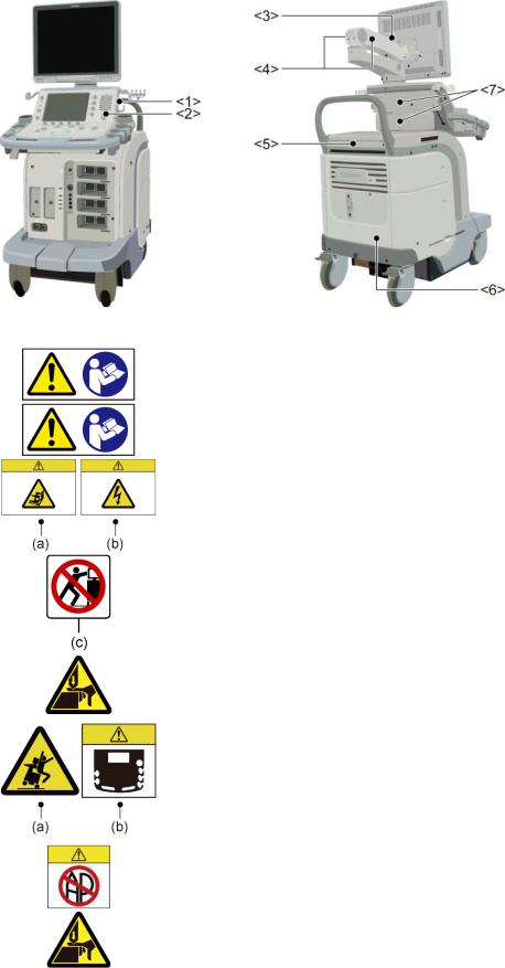
Warning labels on systems complying with the European Directive 93/42/EEC
No. |
Label |
|
Meaning |
<1> |
|
Urges caution related to handling of the transducers. |
|
|
|
For handling of the transducers, refer to the |
|
|
|
transducers' operation manual. |
|
<2> |
|
Cautions that the MI/TI must be controlled as low as |
|
|
|
reasonably achievable. |
|
|
|
|
|
<3> |
|
(a) |
Cautions that the system must be placed on a |
|
|
|
horizontal surface. |
|
|
|
|
|
|
(b) |
Cautions that the cover must not be removed in |
|
|
|
order to prevent electric shock. |
|
|
|
|
|
|
(c) |
Cautions that the system must not be leaned on |
|
|
|
nor pushed from the side. |
|
|
|
|
<4> |
|
Cautions regarding handling of the monitor arm. |
|
|
|
|
|
<5> |
|
(a) |
Cautions against sitting on the system. |
|
|
|
|
|
|
(b) |
Urges caution related to the switches on the |
|
|
|
main panel. |
|
|
|
|
<6> |
|
Cautions that the system must not be used around |
|
|
|
flammable gases. |
|
|
|
|
|
<7> |
|
Cautions that hands may be caught when the height |
|
|
|
of the main panel is adjusted. |
|
|
|
|
|
|
No. 2B771-004EN*M |
||
|
2-10 |
||

Warning labels on other systems
No. |
Label |
|
Meaning |
<1> |
|
|
Cautions that restrict this device to sale by or on the |
|
|
|
order of a physician. (USA/Canada only) |
|
|
|
|
<2> |
|
|
Urges caution related to handling of the transducers. |
|
|
|
|
<3> |
|
|
(a) Cautions that the MI/TI must be controlled as |
|
|
|
low as reasonably achievable. |
|
|
|
(b) As in the USA and Canada, cautions that |
|
|
|
displayed MI/TI are mean values. Refer to |
|
|
|
subsection 24.2.2 "MI/TI display description". |
<4>-1 |
|
|
Cautions that the system must be placed on a |
|
|
|
horizontal surface. |
|
|
|
|
<4>-2 |
|
|
Cautions that the cover must not be removed in |
|
|
|
order to prevent electric shock. |
|
|
|
|
<5> |
|
|
Cautions regarding handling of the monitor arm. |
|
|
|
|
<6> |
|
|
(a) Cautions against sitting or leaning on the |
|
|
|
system. |
|
|
|
(b) Urges caution related to the switches on the |
|
|
|
main panel. |
|
|
No. 2B771-004EN*M |
|
|
|
2-11 |
|

No. |
Label |
Meaning |
<7> |
|
Cautions that the system must not be used around |
|
|
flammable gases. |
|
|
|
<8> |
|
Cautions that hands may be caught when the height |
|
|
of the main panel is adjusted. |
|
|
|
<<Warning labels for options>>
|
Item |
|
Label |
|
Meaning |
|
|
|
|
|
|
Cautions that the Fusion function (option) must |
|
|
|
|
|
|
not be used for patients who use electronic life- |
|
|
Fusion unit |
|
|
|
support devices (for example, a cardiac |
|
|
|
|
|
pacemaker or defibrillator). The magnetic field |
||
|
(UIFR-A500A) |
|
|
|
||
|
|
|
|
generated in Fusion mode may affect such |
||
|
|
|
|
|
||
|
|
|
|
|
devices. |
|
|
|
|
|
|
|
|
|
|
|
|
|
Cautions that the operation manual must be |
|
|
|
|
|
|
referred to. |
|
Fusion Pole Cart |
|
|
|
|
|
|
|
|
|
Cautions that the Fusion pole cart must not be |
|||
(UZWT-A500A) |
|
|
|
|||
|
|
|
leaned on or pushed forcefully from the side. |
|||
|
|
|
|
|
||
|
|
|
|
|
|
|
M-TEE hanger kit |
|
|
|
Precautions related to handling |
||
|
(UAEH-770A) |
|
|
|
1. Place the transducer in the box for |
|
|
Motor drive |
|
|
|
transportation. |
|
M-TEE hanger kit |
|
|
|
2. Do not allow the transducer to bump against |
||
|
(UAEH-002A) |
|
|
|
the main unit. |
|
|
|
|
|
|
|
|
2.11 Regulatory Labels |
|
|
|
|||
|
|
|
|
|
|
|
|
Label |
|
|
Meaning |
|
|
|
|
|
|
This label indicates this device complies with European |
||
|
|
|
|
Directive 93/42/EEC and subsequent amendments. |
||
|
|
|
|
|
|
|
No. 2B771-004EN*M
2-12
2.12Precautions Concerning Clinical Examination Techniques
(1)This operation manual is intended for users who are well-versed in the principles and basic techniques of ultrasound.
(2)This system must be used only by medical personnel fully trained in clinical examination techniques.
(3)This operation manual does not describe clinical examination techniques. Selection of the proper clinical examination technique must be based on specialized training and clinical experience.
No. 2B771-004EN*M
2-13 |
* |
3.General Information on Usage and Maintenance
1.The responsibility for maintenance and management of the product after delivery resides with the customer who has purchased the product.
2.The warranty does not cover the following items, even during the warranty period:
(1)Damage or loss due to misuse or abuse.
(2)Damage or loss caused by Acts of God such as fires, earthquakes, floods, lightning, etc.
(3)Damage or loss caused by failure to meet the specified conditions for this system, such as inadequate power supply, improper installation, or unacceptable environmental conditions.
(4)Damage or loss due to mobile use in a vehicle which is not authorized by TOSHIBA.
(5)Damage or loss due to use outside the territory in which the system was originally sold.
(6)Damage or loss involving system purchased from a source other than TOSHIBA or its authorized distributors or agents.
3.This system shall not be used by persons other than fully qualified and certified medical personnel.
4.Do not make changes or modifications to the software or hardware of this product.
5.In no event shall TOSHIBA be liable for problems, damage, or loss caused by relocation, modification, or repair performed by personnel other than those designated by TOSHIBA.
6.The purpose of this system is to provide physicians with data for clinical diagnosis.
The responsibility for diagnostic procedures lies with the physicians involved. TOSHIBA shall not be liable for the results of diagnostic procedures.
7.Important data must be backed up on external recording media such as clinical records, notebooks, floppy disks, or magnetic tapes.
8.TOSHIBA shall not be liable for loss of data stored in the memory of this system caused by operator error or accidents.
9.This manual contains warnings regarding foreseeable potential dangers. Be alert at all times to dangers other than those indicated.
10.TOSHIBA shall not be liable for damage or loss that results from negligence or from ignoring the precautions and operating instructions contained in this operation manual.
11.Ultrasound transducers are precision equipment and should be handled with proper care. If they are not handled according to the instructions in the operation manual, problems such as scratches, holes, defects in the acoustic lens surface, twisting of the transducer cable, or degradation of the ultrasound images may result.
Note that the warranty does not cover problems caused by improper handling of the transducers.
No. 2B771-004EN*M
3-1

12.TOSHIBA shall not be liable for any error or malfunction that results from use of a transducer other than that specified by TOSHIBA.
13.On the occasion of change of the administrator or manager for this system, be sure to hand over this operation manual.
14.When this system is to be transported, be sure to contact your TOSHIBA service representative first. Special packaging must be performed by a TOSHIBA service engineer or a service engineer authorized by TOSHIBA. TOSHIBA does not assume any responsibility for damage resulting from transportation of this system without consulting TOSHIBA.
15.When disposing of this system, contact your TOSHIBA service representative. Do not dispose of this system without consulting TOSHIBA service representative first. TOSHIBA does not assume any responsibility for damage resulting from disposal of this system without consulting TOSHIBA.
NOTE: Concerning the WEEE label
The following information is only for EU member states: The use of this symbol indicates that this product should not be treated as household waste.
By ensuring that this product is disposed of correctly, you will help prevent potential negative consequences for the environment and human health, which could otherwise be caused by inappropriate waste-handling of this product.
For more detailed information concerning the return and recycling of this product, please consult the supplier from whom you purchased the product.
* For system products, this label may be attached to the main unit only.
NOTE: Concerning BATTERIES
The following information is only for EEA countries: The directive 2006/66/EC requires separate collection and appropriate disposal of spent batteries.
This product also contains batteries that are not intended to be replaced by the user.
Replacement of those batteries will usually be done during regular maintenance or service by service staff who can also arrange proper disposal.
NOTE: Regulatory information
The high-efficiency LCD backlights used in this product contain 5 mg or less of mercury, the disposal of which may be regulated due to environmental considerations.
For disposal or recycling information, please contact your local authorities or the Electronic Industries Alliance (www.eiae.org).
This information is only for the USA.
No. 2B771-004EN*M
3-2
 Loading...