


 Loading...
TOSHIBA Thermal Printer
B-SA4T SERIES
 Maintenance Manual
Document No. EO18-33016A
Original Jul., 2005
(Revised Sep., 2005)
PRINTED IN JAPAN
|
|
|
EO18-33016A |
|
|
|
(Revision Date: Jan. 19,2006) |
|
|
TABLE OF CONTENTS |
|
|
|
|
Page |
1. |
UNPACKING ------------------------------------------------------------------------------------------------------ |
1- 1 |
|
|
1.1 |
Procedure--------------------------------------------------------------------------------------------------- |
1- 1 |
|
1.2 |
Checks ------------------------------------------------------------------------------------------------------ |
1- 2 |
2. |
PRINTER INSTALLATION ------------------------------------------------------------------------------------ |
2- 1 |
|
3. |
MAIN UNIT REPLACEMENT --------------------------------------------------------------------------------- |
3- 1 |
|
|
3.1 |
PS Unit ------------------------------------------------------------------------------------------------------ |
3- 1 |
|
3.2 |
MAIN PC Board Ass’y ----------------------------------------------------------------------------------- |
3- 3 |
|
3.3 |
Platen-------------------------------------------------------------------------------------------------------- |
3- 7 |
|
3.4 |
Stepping Motor and Top Cover Open Sensor (Left)---------------------------------------------- |
3- 8 |
|
3.5 |
Ribbon Motor/Ribbon Sensor------------------------------------------------------------------------------- |
3-11 |
|
3.6 |
Fan Motor-------------------------------------------------------------------------------------------------- |
3-15 |
|
3.7 |
Operation Panel (For the B-SA4TM) --------------------------------------------------------------------- |
3-16 |
|
3.8 |
Operation Panel (For the B-SA4TP)----------------------------------------------------------------- |
3-18 |
|
3.9 |
Print Head--------------------------------------------------------------------------------------------------------- |
3-20 |
|
3.10 |
Media Sensor ---------------------------------------------------------------------------------------------------- |
3-22 |
|
3.11 |
Top Cover Open Sensor (Right) --------------------------------------------------------------------------- |
3-26 |
4. |
PERIODIC MAINTENANCE PROCEDURE --------------------------------------------------------------- |
4- 1 |
|
5. |
TROUBLESHOOTING------------------------------------------------------------------------------------------ |
5- 1 |
|
NOTE:
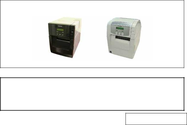
Though the pictures used in this document are mostly those of the B-SA4TM (Metal cover model), the replacement procedures are in common with the B-SA4TP (Plastic cover model).
[B-SA4TM] |
[B-SA4TP] |
CAUTION!
1.This manual may not be copied in whole or in part without prior written permission of TOSHIBA TEC.
2.The contents of this manual may be changed without notification.
3.Please refer to your local Authorised Service representative with regard to any queries you may have in this manual.
Copyright © 2005
by TOSHIBA TEC CORPORATION All Rights Reserved
570 Ohito, Izunokuni-shi, Shizuoka-ken, JAPAN
1. UNPACKING |
EO18-33016A |
1.1 Procedure
1. UNPACKING
1.1 Procedure
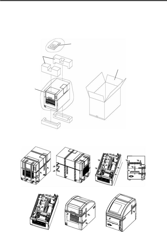
1.Open the carton.
2.Take out the accessories and the top pad from the carton.
3.Take out the printer from the carton.
Accessories
Top Pad
Carton
Printer
4.Remove the tapes from the printer.
[B-SA4TM]
[B-SA4TP]
1- 1
1. UNPACKING |
EO18-33016A |
|
(Revision Date: Jan. 19, 2006) |
|
1.2 Checks |
|
|
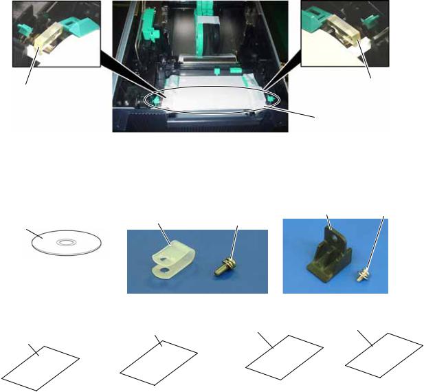
5. Remove the spacers placed on both ends of the platen.
Spacer
Spacer
Platen
1.2 Checks
1.Check for damage or scratches on the printer.
2.Confirm that none of the accessories are missing. The parts below are provided as accessories.
Printer Rear Support |
SMW-4x8 Screw |
Cable Clamp |
SMW-3x8 Screw |
CD-ROM
|
|
|
(B-SA4TM only) |
|
Supply Loading Instructions |
Safety Precautions |
Quality Control Report |
Warranty Disclaimer Sheet |
|
(Doc. No. EO2-33015 for B-SA4TM) |
(Doc. No.: EO2-33016) |
|||
|
|
|||
(Doc. No. EO2-33017 for B-SA4TP) |
|
|
|
NOTE: Keep the carton and pads for later transport.
1- 2
1. UNPACKING |
EO18-33016A |
2. PRINTER INSTALLATION
2. PRINTER INSTALLATION
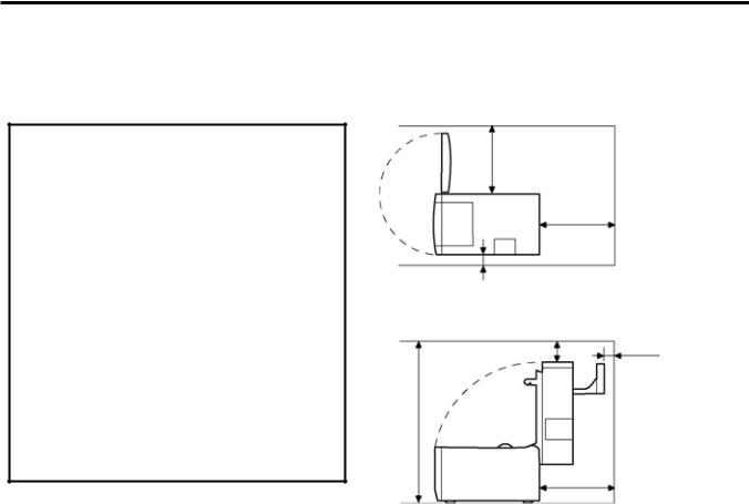
1.Place the printer on the level surface.
2.Keep enough space for replacing and maintenance works while the top cover is opened.
CAUTION! |
300 mm |
|
When installing the printer, take the following |
||
precautions. Failure to do this may cause fire, |
|
|
electric shock, or injury. |
|
|
1. Avoid locations where it is subject to the |
300 mm |
|
following: |
|
|
• Direct sunlight |
|
|
• High temperature, high humidity |
|
|
• Rapid change in temperature |
30 mm |
|
• Excessive vibration |
||
|
||
• Dust |
|
|
2. Keep away from any devices that emit |
30 mm |
|
magnetism or electromagnetic wave. |
||
75 mm |
3.Keep away from flame or moisture.
4.Be sure to place the printer on a level and stable surface.
5. As the enclosure of the B-SA4TP model is |
700 mm |
|
|
made from plastic, do not install the printer |
|
where it might be exposed to oil or solvent. |
|
300 mm
2- 1
3.MAIN UNIT REPLACEMENT
EO18-33016A
(Revision Date: Sep. 27, 2006)
3.1 PS Unit
3. MAIN UNIT REPLACEMENT
WARNING!
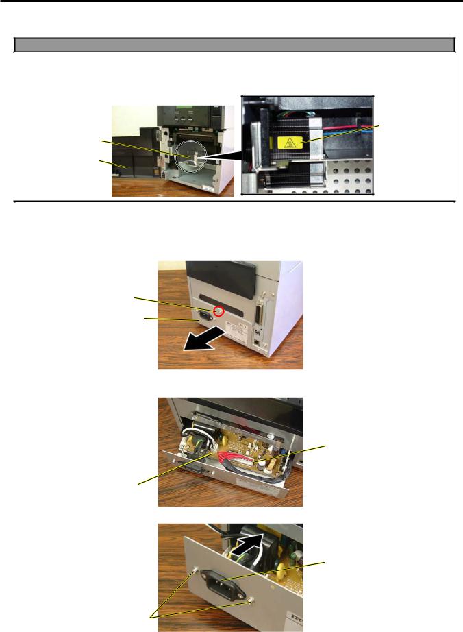
1.Turn the power off and disconnect the power cord before replacing the main parts.
2.The stepping motor becomes hot in about-one-hour batch printing. Never touch the part when opening the front cover during cleaning or maintenance operation. Doing so may cause you to get burned.
Caution Label
Stepping Motor
Front Cover
3.1 PS Unit
1.Remove the screw from the back of the printer, and draw out the PS Unit halfway.
NOTE: If the PS Unit cannot be drawn out smoothly, check whether it gets stuck with the harnesses on both sides.
P-3x6 Screw
PS Unit
2.Unlock the connectors of the cables connected to CN1 and CN2 on the PS PC Board, and disconnect the cables.
CN2
CN1
3. Remove the two screws to detach the Inlet Ass’y.
Inlet Ass’y
SMW-3x6 Screw
3- 1

3.MAIN UNIT REPLACEMENT
EO18-33016A
3.1 PS Unit
4. Remove the screw to release the Ground Wire of the Inlet Ass’y.
Inlet Ass’y
Ground Wire
SMW-4x8 Screw
5. Draw out the PS PC Board Unit from the printer.
PS PC Board Unit
6. Remove the three screws to separate the PS PC Board from the frame.
SMW-3x6
Screw
SMW-3x6 Screw
7. Replace the PS PC Board with a new one, and then reassemble in the reverse order of removal.
NOTES:
1.When inserting the PS Unit into the printer, be careful not to damage or pinch the lead wires by the edge of printer rear plate.
2.Make sure that the Inlet Ass’y is attached so that the ground terminal is positioned upside.
Ground Terminal
3- 2
3.MAIN UNIT REPLACEMENT
EO18-33016A
3.2 MAIN PC Board Ass’y
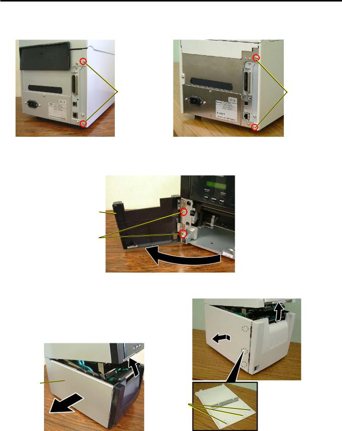
3.2 MAIN PC Board Ass’y
1. Remove the two screws from the back of the printer.
SMW-3x6 Screw |
SMW-3x8* Screw |
[B-SA4TM] |
[B-SA4TP] |
2.Only for the B-SA4TM model, open the Front Cover, and remove the two screws that secure the Front Cover.
Front Cover
SMW-3x6 Screw
3.Close the Front Cover.
4.Slightly open the Top Cover, and remove the Side Panel.
Top Cover 
Side Panel 
Top Cover 
Side Panel
Hook
[B-SA4TM] |
[B-SA4TP] |
5. Close the Top Cover.
3- 3
3.MAIN UNIT REPLACEMENT
EO18-33016A
3.2 MAIN PC Board Ass’y
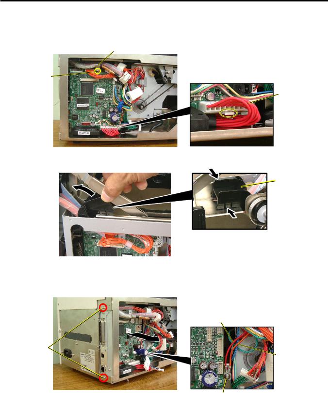
6.Remove the screw to detach the Cable Clamp fixing the Print Head Cable (white).
7.Disconnect the all cables from the MAIN PC Board ass’y.
NOTE: Be careful that the connector of the Power Cable has a connector lock.
Cable Clamp
Print Head Cable
(White) 
SMW-3x8 Screw
Power Cable
 Connector Lock
8.To easily remove the MAIN PC board from the B-SA4TM model, remove the cable protection cover by squeezing and raising it.
Cable Protection
Cover
9.Remove the two screws from the printer back. Also, remove the screw which secures the MAIN PC board together with the ground wires (orange and red lead wires).
10.Remove the MAIN PC board Ass’y from the printer.
NOTE: Be careful not to hit the component parts on the MAIN PC board against the printer frame.
|
Red Lead Wire |
|
P-3x6 Screw |
|
|
and Toothed |
Orange Lead Wire |
|
Washer |
||
|
SMW-3x6 Screw
3- 4
3.MAIN UNIT REPLACEMENT
EO18-33016A
3.2 MAIN PC Board Ass’y
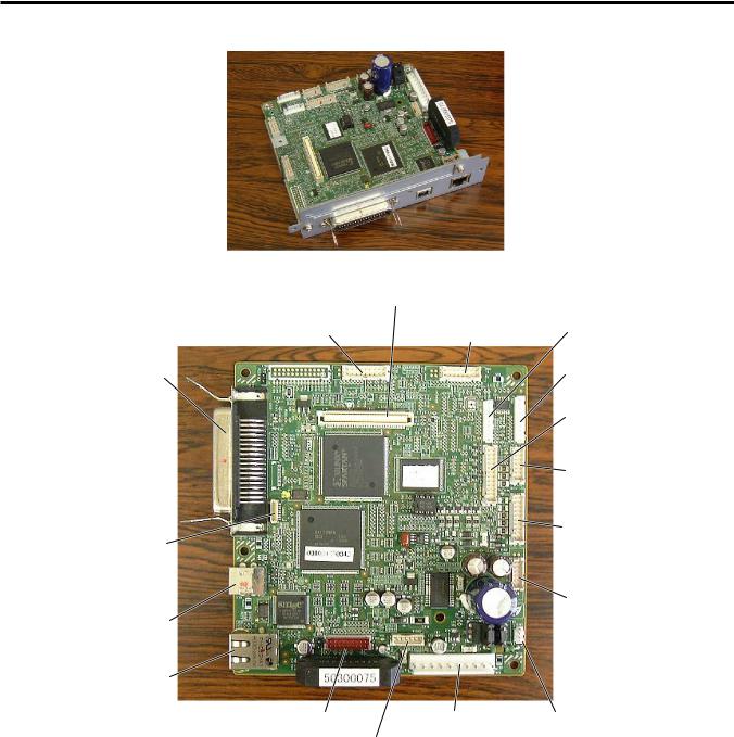
11. Replace the MAIN PC board with a new one, and reassemble in the reverse order of removal.
CN11 External I/O (Not used) |
|
|
|
|
|
|
CN13 |
CN9 |
|
CN6 |
|||
Panel PCB |
Print Head, Signal |
|
Serial Interface |
|||
CN19 |
|
|
|
|
|
|
|
|
|
CN4 |
|||
Parallel I/F |
|
|
|
Expansion I/O PCB |
||
|
|
|
|
|
|
|
|
|
|
|
CN5 |
|
|
|
|
|
|
Sensors |
|
|
|
|
|
|
|
|
|
|
|
|
|
|||
|
|
|
CN3 |
|
||
|
|
|
Option |
|
||
|
|
|
|
|
||
CN501 |
|
CN2 |
||||
|
Ribbon Motor |
|||||
AUD/RTC |
|
|||||
|
|
|
|
|
|
|
(Not used) |
|
|
|
|
|
|
|
|
|
|
CN1 |
||
CN18 |
|
|
|
Print Head, Power |
||
USB I/F |
|
|
|
|
|
|
CN17 |
|
|
|
|
|
|
LAN I/F |
|
|
|
|
|
|
CN12 SIO PC Board |
CN8 Power Supply |
CN10 Fan |
||||
CN500 Stepping Motor
3- 5
3.MAIN UNIT REPLACEMENT
NOTES:
EO18-33016A
3.2 MAIN PC Board Ass’y
1.When re-attaching the Side Panel, be careful not to pinch the lead wires between the printer frames and the Side Panel.
Be careful not to pinch the lead wires by the Side Panel.
2.After installing the MAIN PC board, place the cables and harnesses as shown below, and bind them with cable clamps so as not to touch the stepping motor pulley or timing belt.
 Timing Belt
 Stepping Motor
Pulley
3- 6
3.MAIN UNIT REPLACEMENT
3.3 Platen
EO18-33016A
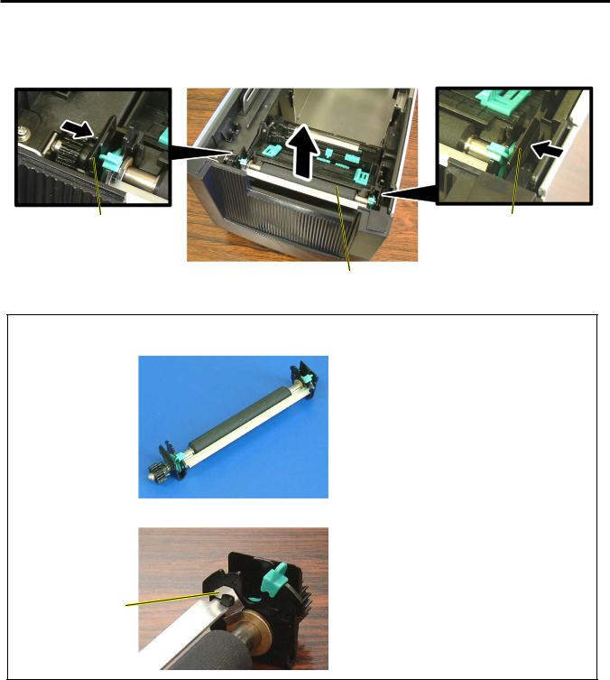
3.3 Platen
1.Open the Top Cover.
2.Push both Platen Holders inside to release the hooks, and lift the Platen Ass’y.
Platen Holder |
Platen Holder |
Platen Ass’y
NOTES:
1. Do not disassemble the Platen Ass’y further as a Platen Ass’y is a minimum unit.
2. Be careful that the metal plate easily comes off. If it does, fit it as the following picture shows.
Metal Plate
3. Replace the Platen Ass’y with a new one, and then reassemble in the reverse order of removal.
3- 7
3.MAIN UNIT REPLACEMENT
EO18-33016A
3.4 Stepping Motor and Top Cover Open Sensor (Left)
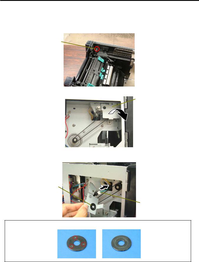
3.4 Stepping Motor and Top Cover Open Sensor (Left)
1.Remove the Side Panel from the printer. (Refer to Section 3.2.)
2.Remove the Platen Ass’y. (Refer to Section 3.3.)
3.Open the Top Cover and remove the screw which secures the Stepping Motor Frame.
SMW-3x6 Screw
4. Remove the screw to detach the Platen Gear Frame.
Platen Gear Frame
 SMW-3x6 Screw
5.Remove the Platen Pulley Spacer together with the Platen Gear Frame.
6.Disconnect the Top Cover Open Sensor Cable.
Platen Pulley Spacer
Top Cover Open Sensor (Left)
NOTE: The Platen Pulley Spacer can be attached in either orientation.
3- 8
3.MAIN UNIT REPLACEMENT
EO18-33016A
3.4 Stepping Motor and Top Cover Open Sensor (Left)
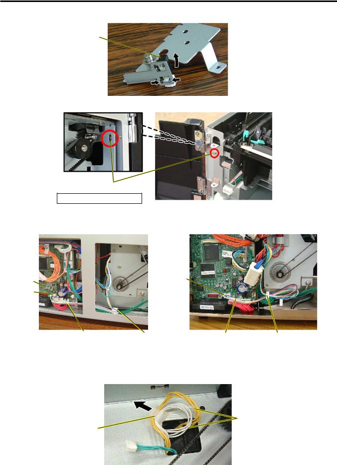
7.If necessary, remove the Top Cover Open Sensor (Left) by releasing the two hooks.
Top Cover Open
Sensor (Left)
8.Loosen the Motor Frame Locating Screw, on the upper left of the printer front.
Motor Frame Locating Screw
Do not remove, just loosen!
9.Disconnect the Stepping Motor cable from CN500 on the MAIN PC Board.
10.Release the Stepping Motor Cable from the Cable Clamp.
MAIN PC |
CN500 |
Board |
|
CN500 |
|
Stepping Motor Cable |
Cable Clamp |
Stepping Motor Cable |
Cable Clamp |
[B-SA4TM] |
|
[B-SA4TP] |
|
11.Release the two Media Sensor Harnesses (yellow and white) from the cable clamp.
NOTE: When fixing the Media Sensor Harnesses with the cable clamp, leave adequate slack so that they would not be disconnected even when the media sensor is moved to the rightmost position.
Media Sensor Harness
Cable Clamp
3- 9
Loading...