


Maytag ACO1520AC, ACO1560AW, ACO1840AB, ACO1530AW, ACO1560AB User Manual
...Service
Over The Range 2001 and 2002
Domestic Microwave Ovens
This manual replaces RS2100011 Revision 0.
Service Manual for:
Amana®
Jenn-Air®
Maytag®
This manual is to be used by qualified appliance technicians only. Maytag does not assume any responsibility for property damage or personal injury for improper service procedures done by an unqualified person.
Models and manufacturing numbers in this manual.
2002 models are listed in bold.
ACO1520AB
ACO1520AC
ACO1520AW
ACO1530AB
ACO1530AW
ACO1560AB
ACO1560AC
ACO1560AS
ACO1560AW
ACO1840AB
ACO1840AC
ACO1840AW
ACO1860AB
ACO1860AC
ACO1860AS
ACO1860AW
JMV8196AAB
JMV8196AAQ
JMV8196AAS
JMV8196AAW
MMV4184AAB
MMV4184AAQ
MMV4184AAW
MMV5156AAB
MMV5156AAQ
MMV5156AAS
MMV5156AAW
MMV5186AAB
MMV5186AAQ
MMV5186AAS
MMV5186AAW
MVHRK3
MVHRK4
16021668 Revision 0 September 2002
Important Information
Pride and workmanship go into every product to provide our customers with quality products. It is possible, however, that during its lifetime a product may require service. Products should be serviced only by a qualified service technician who is familiar with the safety procedures required in the repair and who is equipped with the proper tools, parts, testing instruments and the appropriate service manual. REVIEW ALL SERVICE INFORMATION
IN THE APPROPRIATE SERVICE MANUAL BEFORE BEGINNING REPAIRS.
Important Notices for Consumers and Servicers
!WARNING
To avoid risk of serious injury or death, repairs should not be attempted by an unauthorized personal, dangerous conditions (such as exposure to electrical shock) may result.
!CAUTION
Maytag will not be responsible for any injury or property damage from improper service procedures. If performing service on your own product, assume responsibility for any personal injury or property damage which may result.
To locate an authorized servicer, please consult your telephone book or the dealer from whom you purchased this product. For further assistance, please contact:
Customer Service Support Center
CAIR Center |
|
Web Site |
Telephone Number |
WWW.AMANA.COM ............................................... |
1-800-843-0304 |
WWW.JENNAIR.COM ............................................ |
1-800-536-6247 |
WWW.MAYTAG.COM ............................................. |
1-800-688-9900 |
CAIR Center in Canada .......................................... |
1-800-688-2002 |
Amana Canada Product .......................................... |
1-866-587-2002 |
Recognize Safety Symbols, Words, and Labels
!DANGER
DANGER—Immediate hazards which WILL result in severe personal injury or death.
!WARNING
WARNING—Hazards or unsafe practices which COULD result in severe personal injury or death.
!CAUTION
CAUTION—Hazards or unsafe practices which COULD result in minor personal injury or product or property damage.
16021668 Rev. 0 |
2 |
©2002 Maytag Appliances Company |
Table of Contents |
|
Important Information ................................................... |
2 |
Important Product Information ...................................... |
4 |
Important Safety Information ........................................ |
5 |
Microwave Leakage Testing ......................................... |
6 |
General Information |
|
Location of Model Number ........................................ |
7 |
Model Identification ................................................... |
7 |
Parts and Accessories .............................................. |
7 |
Service ...................................................................... |
7 |
Asure™ Extended Service Plan ................................ |
7 |
Oven Specifications ACO15* Models ........................ |
7 |
Oven Specifications ACO18* Models ........................ |
7 |
Electrical Rating ........................................................ |
7 |
Electrical Requirements ............................................ |
7 |
Grounding Instructions .............................................. |
8 |
Microwave Oven Description .................................... |
8 |
Testing Procedures |
|
Primary Interlock Switch Test .................................... |
9 |
Secondary Interlock Switch Test ............................... |
9 |
Interlock Monitor Switch Test .................................... |
9 |
Magnetron ................................................................. |
9 |
High Voltage Transformer ....................................... |
9 |
High Voltage Capacitor ........................................... |
10 |
High Voltage Diode ................................................. |
10 |
Humidity Sensor ...................................................... |
10 |
Relay ....................................................................... |
10 |
Control Key Panel .................................................... |
10 |
Circuit Board ........................................................... |
12 |
Fuse ........................................................................ |
12 |
Fan Motor ................................................................ |
12 |
Oven Thermostat .................................................... |
12 |
Base Thermostat - ACO18*, JMV8196*, |
|
MMV4184*, and MMV5186* only ......................... |
12 |
Magnetron Thermal Fuse - ACO18*, JMV8196*, |
|
MMV4184*, and MMV5186* only ......................... |
12 |
Surge Resistor ........................................................ |
12 |
Troubleshooting Procedures ...................................... |
13 |
Disassembly Procedures |
|
Grille ........................................................................ |
18 |
Door Assembly ........................................................ |
18 |
Door Disassembly ................................................... |
18 |
Control Panel .......................................................... |
19 |
P.C. Board ............................................................... |
19 |
Control Key Panel ................................................... |
20 |
Outer Case .............................................................. |
20 |
Stirrer Assembly (some models) ............................. |
21 |
Interlock Door Latch Switches ................................ |
21 |
High Voltage Capacitor ........................................... |
22 |
Diode ....................................................................... |
22 |
Transformer ............................................................ |
23 |
Fuse ........................................................................ |
23 |
Magnetron ............................................................... |
23 |
Magnetron Fan Assembly ....................................... |
23 |
Magnetron Thermal Fuse ........................................ |
24 |
Humidity Sensor ...................................................... |
24 |
Oven Thermostat .................................................... |
24 |
Base Thermostat ..................................................... |
25 |
Light Socket ............................................................ |
25 |
Turntable Motor ....................................................... |
25 |
Vent Blower ............................................................. |
25 |
Wiring Diagrams And Schematics |
|
ACO1520* and ACO1530* Models ......................... |
26 |
ACO1560* and MMV5156* Models ......................... |
27 |
ACO18*, JMV8196*, MMV4184*, and |
|
MMV5186* Models ............................................... |
28 |
Appendix A |
|
Installation Instructions |
|
Parts, Tools, and Materials .................................. |
A-4 |
Preparing Electrical Connection .......................... |
A-5 |
Preparing Venting System .................................. |
A-5 |
Preparing Venting Blower .................................... |
A-7 |
Preparing Wall and Upper Cabinet ..................... |
A-8 |
Attaching Oven to the Wall ............................... |
A-10 |
Appendix B |
|
Care and Cleaning .............................................. |
B-2 |
©2002 Maytag Appliances Company |
3 |
16021668 Rev. 0 3 |
Important Product Information
!WARNING
Precautions to be observed before and during servicing to avoid possible exposure to excessive microwave energy or electrical shock, disconnect power to oven.
(A)Do not operate or allow oven to be operated with door open.
(B)Make the following safety checks on all ovens to be serviced before activating the magnetron or other microwave source, and make repairs as necessary:
•Interlock operation
•Proper door closing
•Seal and sealing surfaces (arcing, wear, and other damage)
•Damage to or loosening of hinges and latches
•Evidence of dropping or abuse
(C)Before turning on microwave power for any service test or inspection within the microwave generating compartments, check the magnetron, waveguide or transmission line, and cavity for proper alignment, integrity, and connections.
(D)Any failed or misadjusted components in the interlock, monitor, door seal, and microwave generation and transmission systems shall be repaired, replaced or adjusted by procedures described in this manual before oven is released to the consumer.
(E)Check microwave leakage to verify compliance with the federal performance standard should be performed on each oven prior to release to the consumer.
Wiring
Good service practice is to never route wiring over terminals and/or sharp edges. This applies to any wiring without regard to the circuit voltage. Wire insulation material and thickness is designed and regulated for electrical spacing purpose only, but cannot always be relied upon because of possible cuts and/or abrasions, which can occur during servicing.
!WARNING
To avoid risk of electrical shock, injury or death, make sure these grounding instructions are followed.
Grounding Instructions
!WARNING
Do not remove grounding prong when installing grounded appliance in a home or business that does not have three wire grounding receptacle. Under no condition is grounding prong to be cut off or removed. It is the personal responsibility of the consumer to contact a qualified electrician and have a properly grounded three prong wall receptacle installed in accordance with appropriate electrical codes
Servicing of Grounded Products
The standard accepted color coding for grounding wires is GREEN or GREEN WITH YELLOW STRIPE. These ground leads are NOT to be used as current carrying conductors. It is extremely important that the technician replace any and all grounds prior to completion of the service call. Under no condition should ground wire be left off causing a potential hazard to technicians and consumer.
16021668 Rev. 0 |
4 |
©2002 Maytag Appliances Company |
Important Safety Information
!CAUTION
Read the following information to avoid possible exposure to microwave radiation:
The basic design of the Maytag microwave oven makes it an inherently safe device to both use and service. However, there are some precautions which should be followed when servicing the microwave oven to maintain this safety. These are as follows:
1.Always operate the unit from an adequately grounded outlet. Do not operate on a two-wire extension cord.
2.Before servicing the unit (if unit is operable) perform the microwave leakage test.
3.The oven should never be operated if the door does not fit properly against the seal; the hinges or hinge bearings are damaged or broken; the choke is damaged, (pieces missing, etc.); or any other visible damage can be noted. Check the choke area to ensure that this area is clean and free of all foreign matter.
4.If the oven operates with the door open and produces microwave energy, take the following steps.
A.Tell the user not to operate the oven.
B.Contact Maytag immediately.
5.Always have the oven disconnected when the outer case is removed except when making the "live" tests called for in the Service Manual. Do not reach into the equipment area while the unit is energized. Make all connections for the test and check them for tightness before plugging the cord into the outlet.
6.Always ground the capacitors on the magnetron filter box and H. V. Capacitor with an insulated-handle screwdriver before working in the high voltage area of the equipment compartment. Some types of failures will leave a charge in these capacitors and the discharge could cause a reflex action which could make you injure yourself.
7.In the area of the transformer, capacitor, diode, and magnetron there is HIGH VOLTAGE. When the unit is operating - keep this area clean and free of anything which could possibly cause an arc or ground, etc.
8.Do not for any reason defeat the interlock switches, there is no valid reason for this action at any time; nor will it be condoned by Maytag.
9.IMPORTANT: Before returning a microwave to a customer, check for proper switch interlock action. The primary and secondary switches MUST open when the door is actuated. The monitor switch MUST close at a 1/4 inch when the door is opened.
10.Before returning a microwave to a customer, verify the door spacing is reasonably uniform along the top, bottom, and sides and that it measures 1/8 inch or less.
11.The Maytag microwave oven should never be operated with:
•Any components removed and/or bypassed.
•Any of the safety interlocks are found to be failed.
•Any of the seal surfaces are defective, missing, or damaged.
12.To ensure that the unit does not emit excessive microwave leakage and to meet the Department of Health Human Service guidelines, check the oven for microwave leakage using Narda Model 8110B, Holaday HI-1501, HI-1510, and HI-1710 leakage monitor as outlined in the instructions. The maximum leakage level allowed is 4mW/cm2.
13.If servicer encounters an emission reading over 4mw/cm2 the servicer is to cease repair and contact the Maytag Service Department immediately for further direction. Maytag will contact the proper Government Agency upon verification of the test results.
©2002 Maytag Appliances Company |
5 |
16021668 Rev. 0 |
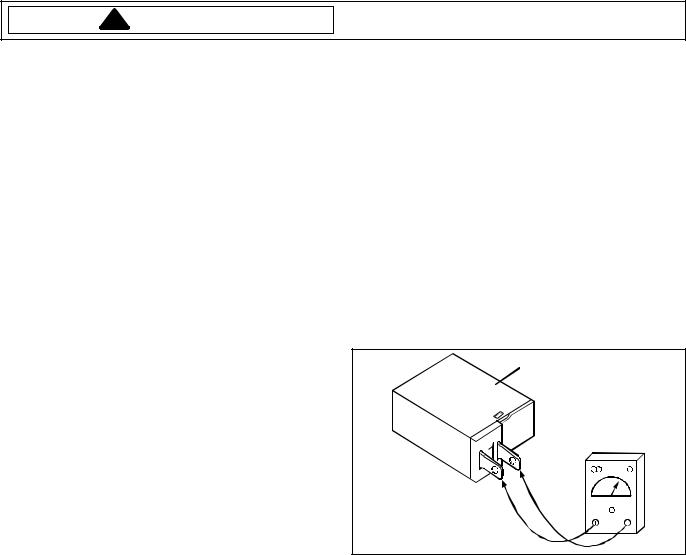
Microwave Leakage Testing
!WARNING
Check for radiation leakage after servicing. Should the leakage be more than 4mW/cm2 inform Maytag immediately. After repairing or replacing any radiation safety device, keep a written record for future reference, as required by DHHS and HEW regulations. This requirement must be strictly observed. In addition, the leakage reading must be recorded on the service repair ticket while in the customer’s home.
Measurement With the Outer Panel
Removed
!DANGER
Avoid contacting any high voltage components.
Whenever you replace the magnetron, measure for radiation leakage before the outer panel is installed and after all necessary components are replaced or adjusted. Special care should be taken in measuring around the magnetron.
Equipment
•Electromagnetic radiation monitor
•600 cc glass beaker
Procedure For Measuring Radiation Leakage
Note before measuring -
•Do not exceed meter full scale deflection. Leak monitor should initially be set to the highest scale.
•To prevent false readings, the test probe should be held by the grip portion of the handle only.
•The scan speed is equal to one inch per antenna revolution or one inch per second if antenna speed is unknown.
•Areas to be checked are all door seal areas and any venting parts.
•Leakage with the outer panel removed...4mW/cm2 or less.
•Leakage for fully assembled oven with door normally closed ...4mW/cm2 or less.
•Leakage for a fully assembled oven (before the latch switch (primary) is interrupted) while pulling the
door ... 4mW/cm2 or less.
1 . Pour 275 ±15 cc (9 oz ±1/2 oz) of 20 ±5°C (68 ±9°F) water in a beaker which is graduated to 600 cc and place the beaker in the center of oven.
2.Set the radiation monitor to 2450 MHz and use it following the manufacturer’s recommended test procedure to assure correct results.
3.While measuring the leakage, always use the 2–inch (5 cm) spacer supplied with the probe.
4.Press the start pad or turn on the timer and with the magnetron oscillating, measure the leakage by holding the probe perpendicular to the surface being measured.
Measurement With a Fully Assembled Oven
After all components, including the outer panel are fully assembled, measure for radiation leakage around the door periphery, the door viewing window, the exhaust opening, and air inlet openings.
Record Keeping and Notification After
Measurement
1.After any adjustment or repair to a microwave oven, a leakage reading must be taken. Record this leakage reading on the repair ticket even if it is zero.
2.A copy of the repair ticket and the microwave leakage reading should be kept by the repair facility.
16021668 Rev. 0 |
6 |
©2002 Maytag Appliances Company |
General Information
Please read the owner’s manual information. It will tell how to use all the features of this microwave oven.
Location of Model Number
To request service information or replacement parts, the service center will require the complete model number of your microwave oven. The number is located on the oven front as shown in the illustration below.
Model Number Label |
Model Identification
Complete enclosed registration card and promptly return. If registration card is missing:
•For Amana product call 1-800-843-0304 or visit the Web Site at www.amana.com
•For Maytag product call 1-800-688-9900 or visit the Web Site at www.maytag.com
•For Jenn-Air product call 1-800-536-6247 or visit the Web Site at www.jennair.com
•For product in Canada call 1-866-587-2002 or visit the Web Sites at www.amana.com or www.maytag.com or www.jennair.com
When contacting provide product information located on rating plate. Record the following:
Model Number: |
___________________ |
Manufacturing Number: |
___________________ |
Serial or S/N Number: |
___________________ |
Date of purchase: |
___________________ |
Dealer’s name and address: |
___________________ |
Service
Keep a copy of sales receipt for future reference or in case warranty service is required. To locate an authorized servicer:
•For Amana product call 1-800-628-5782 or visit the Web Site at www.amana.com
•For Maytag/Jenn-Air product call 1-800-462-9824 or visit the Web Site at www.maytag.com or www.jennair.com
•For product in Canada call 1-866-587-2002 or visit the Web Sites at www.amana.com or www.maytag.com or www.jennair.com
Warranty service must be performed by an authorized servicer. We also recommend contacting an authorized servicer, if service is required after warranty expires.
Parts and Accessories
Purchase replacement parts and accessories over the phone. To order accessories for your product call:
•For Amana product call 1-877-232-6771 or visit the Web Site at www.amana.com
•For Maytag/Jenn-Air product call 1-800-462-9824 or visit the Web Site at www.maytag.com or www.jennair.com
•For product in Canada call 1-866-587-2002 or visit the Web Sites at www.amana.com or www.maytag.com or www.jennair.com
Extended Service Plan
We offer long-term service protection for this new oven.
•Asure™ Extended Service Plan is specially designed to supplement Amana’s strong warranty. This plan covers parts, labor, and travel charges.
Call 1-866-232-6244 for information.
•Dependability PlusSM Extended Service Plan is specially designed to supplement Maytag’s and Jenn-Air’s strong warranty. This plan covers parts, labor, and travel charges.
Call 1-800-925-2020 for information.
Oven Specifications ACO15* and MMV5156*
Models
Output Power |
1000 W (IEC 705) |
Outer Dimensions |
29-15/16" x 16-7/16" x 15-5/8" |
Oven Cavity Dimensions |
19-7/8" x 14-3/16" x 15-3/8" |
Cavity Volume |
1.5 cu. ft. |
Net Weight |
65 lbs. |
Oven Specifications ACO18*, MMV4184* and
MMV5186* Models
Output Power |
1000 W (IEC 705) |
Outer Dimensions |
29-15/16" x 16-7/16" x 15-3/8" |
Oven Cavity Dimensions |
22-3/8" x 10" x 14-19/32" |
Cavity Volume |
1.8 cu. ft. |
Net Weight |
65 lbs. |
Oven Specifications JMV8196* Models
Output Power |
850 W (IEC 705) |
Outer Dimensions |
29-15/16" x 16-7/16" x 15-3/8" |
Oven Cavity Dimensions |
22-3/8" x 10" x 14-19/32" |
Cavity Volume |
1.9 cu. ft. |
Net Weight |
65 lbs. |
Electrical Requirements
The oven is designed to operate on a Standard
120V / 60Hz household outlet. Be sure the circuit is at least 20 Amps and the microwave oven is the only appliance on the circuit.
NOTE: It is not designed for 50Hz or any circuit other than a 120V / 60Hz circuit.
©2002 Maytag Appliances Company |
7 |
16021668 Rev. 0 |

General Information
Grounding Instructions
This appliance must be grounded. If an electrical short circuit occurs, grounding reduces the risk of electric shock by providing an escape wire for the electric current. The cord for this appliance has a grounding wire with a grounding plug. Put the plug into an outlet that is properly installed and grounded.
!WARNING
To avoid risk of electric shock, personal injury or death, use grounding plug properly.
Ask a qualified electrician if you do not understand the grounding instructions or if you wonder whether the appliance is properly grounded.
Because this appliance fits under the cabinet, it has a short power-supply cord. See the Installation Instructions for directions on placing the cord properly. Keep the electrical power cord dry and do not pinch or crush it in any way.
Properly Polarized and
Grounded Outlet
Three-Pronged (Grounding) Plug
For a permanently connected appliance: This appliance must be connected to a grounded, metallic, permanent wiring system, or an equipment grounding conductor should be run with the circuit conductors and connected to the equipment grounding terminal or lead on the appliance.
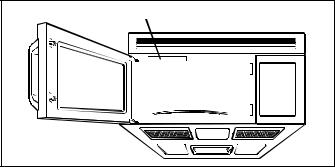
Microwave Oven Description
Model and serial
|
number plate |
Vent grille |
|
|
|
Window with |
Glass turntable |
|
|
|
|
metal shield |
|
Cooking guide |
Door handle |
|
|
|
|
|
Door safety |
Oven control |
lock system |
panel |
|
Cooktop/countertop light |
|
Grease filter |
16021668 Rev. 0 |
8 |
©2002 Maytag Appliances Company |

Testing Procedures
! |
WARNING |
Disconnect power before performing the following |
procedures unless testing requires it. |
||
|
|
|
NOTES: |
|
Interlock Monitor Switch Test |
•Perform microwave energy leakage test if unit is serviced for any reason.
•Verify wire leads are connected to correct positions.
•When removing wire terminal plugs from connectors, grasp the connector, not the wires.
Primary Interlock Switch Test
When the door is opened slowly, an audible click should be heard. If the latch does not activate the switch when the door is closed, the switch should be adjusted in accordance with the adjustment procedure.
1.Disconnect power to oven and remove control panel, (see “Control Panel” section in Disassembly Procedure).
2.Discharge high voltage capacitor, (see "High Voltage Capacitor" section in Disassembly Procedure).
3.Disconnect wire leads from switch.
4.Perform a continuity test by connecting one meter lead on COM terminal and the other meter lead on NO terminal.
Readings should be as follows:
Door closed ................. 0 ohms Door opened ............... Infinite ohms
When the door is opened slowly, an audible click should be heard. If the latch does not activate the switch when the door is closed, the switch should be adjusted in accordance with the adjustment procedure.
1.Disconnect power to oven and remove control panel, (see “Control Panel” section in Disassembly Procedure).
2.Discharge high voltage capacitor, (see "High Voltage Capacitor" section in Disassembly Procedure).
3.Disconnect wire leads from switch.
4.Perform a continuity test by connecting one meter lead on COM terminal and the other meter lead on NC terminal.
Readings should be as follows:
Door closed ................. Infinite ohms Door opened ............... 0 ohms
NOTE: When replacing component use identical replacement part.
NOTE: After repairing the door or the interlock system, it is necessary to do a continuity test before operating the oven.
NOTE: When replacing component use identical replacement part.
NOTE: After repairing the door or the interlock system, it is necessary to do a continuity test before operating the oven.
Secondary Interlock Switch Test
When the door is opened slowly, an audible click should be heard. If the latch does not activate the switch when the door is closed, the switch should be adjusted in accordance with the adjustment procedure.
1.Disconnect power to oven and remove control panel, (see “Control Panel” section in Disassembly Procedure).
2.Discharge high voltage capacitor, (see "High Voltage Capacitor" section in Disassembly Procedure).
3.Disconnect wire leads from switch.
4.Perform a continuity test by connecting one meter lead on COM terminal and the other meter lead on NO terminal.
Readings should be as follows:
Door closed ................. 0 ohms Door opened ............... Infinite ohms
NOTE: When replacing component use identical replacement part.
NOTE: After repairing the door or the interlock system, it is necessary to do a continuity test before operating the oven.
Magnetron
1.Disconnect power to oven and remove control panel, (see “Control Panel” section in Disassembly Procedure).
2.Discharge high voltage capacitor, (see "High Voltage Capacitor" section in Disassembly Procedure).
3.Disconnect wire leads to magnetron.
4.Measure the resistance across filament terminals of the magnetron.
Reading should be less than 1 ohm.
5.Measure the resistance from each filament terminal to ground. Reading should indicate infinite ohms.
NOTE: Any other readings then what should be indicated, magnetron needs to be replaced.
NOTE: Replace the magnetron, if magnetron indications are good and all other high voltage components test good, but the unit still does not heat a load.
High Voltage Transformer
1.Disconnect power to oven and remove control panel, (see “Control Panel” section in Disassembly Procedure).
2.Discharge high voltage capacitor, (see "High Voltage Capacitor" section in Disassembly Procedure).
3.Disconnect wire leads to high voltage transformer.
©2002 Maytag Appliances Company |
9 |
16021668 Rev. 0 |
Testing Procedures
!WARNING
Disconnect power before performing the following procedures unless testing requires it.
4.Measure resistance of the terminals on the high voltage transformer with meter on R x 1 scale.
Reading should be indicated as follows:
Primary winding ......less than 1.0 ohms Filament winding ....less than 1.0 ohms
Secondary winding .approximately 50 to 120 ohms
5.Measure resistance of the terminals on the high voltage transformer with meter on high scale.
Reading should be indicated as follows:
Primary winding to ground ....... Infinite ohms Filament winding to ground ..... Infinite ohms
High Voltage Capacitor
1.Disconnect power to oven and remove control panel, (see “Control Panel” section in Disassembly Procedure).
2.Discharge high voltage capacitor, (see "High Voltage Capacitor" section in Disassembly Procedure).
3.Disconnect wire leads to high voltage capacitor.
4.Measure resistance of capacitor from terminal to terminal.
•Normal reading—momentarily indicates several ohms and then gradually returns to infinite ohms.
•Abnormal reading—Indicates continuity or infinite ohms.
5.Measure resistance of capacitor from terminal to case.
•Normal reading—Indicates infinite ohms
•Abnormal reading—Indicates continuity
High Voltage Diode
1.Disconnect power to oven and remove control panel, (see “Control Panel” section in Disassembly Procedure).
2.Discharge high voltage capacitor, (see "High Voltage Capacitor" section in Disassembly Procedure).
3.Disconnect wire leads to high voltage diode.
4.Measure resistance of diode in forward bias.
•Normal reading—Indicates continuity
•Abnormal reading—Indicates infinite ohms
5.Measure resistance of diode in reverse bias.
•Normal reading—Indicates infinite ohms
•Abnormal reading—Indicates continuity
Humidity Sensor
1.Disconnect power to oven and remove control panel, (see “Control Panel” section in Disassembly Procedure).
2.Discharge high voltage capacitor, (see "High Voltage Capacitor" section in Disassembly Procedure).
3.Disconnect wire terminal plug from control board (CN5).
4.Measure the following terminals with meter on R x 1000 scale.
Normal indication:
Terminal 1 to terminal 2 ......... 4.5K to 6.2K ohms Terminal 2 to terminal 3 ........ 2.0K to 3.5K ohms Terminal 1 to terminal 3 ........ 2.0K to 3.5K ohms
Abnormal indication:
Infinite or several ohms
Relay
1.Disconnect power to oven and remove control panel, (see “Control Panel” section in Disassembly Procedure).
2.Discharge high voltage capacitor, (see "High Voltage Capacitor" section in Disassembly Procedure).
3.Disconnect wire terminal plug from control board (ACO18*, RY2) (ACO15*, RY7), and operate the unit.
Relay 2 |
Power Level |
Cycles On for: |
Cycles Off for: |
|
|
|
1 |
4 seconds |
18 seconds |
2 |
6 seconds |
16 seconds |
3 |
8 seconds |
14 seconds |
4 |
10 seconds |
12 seconds |
5 |
12 seconds |
10 seconds |
6 |
14 seconds |
8 seconds |
7 |
16 seconds |
6 seconds |
8 |
18 seconds |
4 seconds |
9 |
20 seconds |
2 seconds |
10 |
22 seconds |
0 seconds |
|
|
|
Control Key Panel
1.Disconnect power to oven and remove control panel, (see “Control Panel” section in Disassembly Procedure).
2.Discharge high voltage capacitor, (see "High Voltage Capacitor" section in Disassembly Procedure).
16021668 Rev. 0 |
10 |
©2002 Maytag Appliances Company |
Testing Procedures
!WARNING
Disconnect power before performing the following procedures unless testing requires it.
3.Disconnect ribbon connector by siding top part of connector upward. Once in released position remove ribbon from connector by siding ribbon side-to-side.
NOTE: Caution should be used when removing cable from connector. Ribbon cable has two holes which holds the lock ribbon in place.
NOTE: Circuit board has numbers 1 and 13 on it for identification.

 1
1
2

 3
3
4
5
6
7

 8
8
9

 10
10

 11
11

 12
12 
 13
13
ACO1520/ACO1530 models
Pad |
Conn. |
|
Pad |
Conn. |
||
|
||||||
Vent HI/LOW/OFF |
1 |
- 8 |
|
Auto Defrost |
5 |
- 9 |
Light HI/LOW/OFF |
1 - 9 |
|
Kitchen Timer 5 |
- 10 |
||
Control Setup |
2 - 9 |
|
Power Level |
5 |
- 11 |
|
Clock |
2 |
- 10 |
|
Hold Warm |
5 |
- 12 |
Stop Clear |
2 |
- 12 |
|
5 |
6 |
- 8 |
Auto Cook |
3 - 8 |
|
6 |
6 |
- 9 |
|
Auto Reheat |
3 - 9 |
|
7 |
6 |
- 10 |
|
Easy Cook |
3 |
- 10 |
|
8 |
6 |
- 11 |
Start |
3 |
- 12 |
|
9 |
6 |
- 12 |
Frozen Entree |
3 |
- 13 |
|
0 |
7 |
- 8 |
Popcorn |
4 - 8 |
|
1 |
7 |
- 9 |
|
Potato |
4 - 9 |
|
2 |
7 |
- 10 |
|
Beverage |
4 |
- 10 |
|
3 |
7 |
- 11 |
Pizza |
4 |
- 11 |
|
4 |
7 |
- 12 |
Program |
5 - 8 |
|
|
|
|
|
|
|
|
|
|
||
ACO1560/MMV5156 models |
|
|
|
|
||
|
|
|
|
|
||
Pad |
Conn. |
|
Pad |
Conn. |
||
Vent HI/LOW/OFF |
1 |
- 8 |
|
Auto Defrost |
5 |
- 9 |
Light HI/LOW/OFF |
1 - 9 |
|
Kitchen Timer |
5 |
- 10 |
|
Less |
1 |
- 10 |
|
Power Level |
5 |
- 11 |
Favorite Recipe |
1 |
- 11 |
|
Hold Warm |
5 |
- 12 |
T/Table ON/OFF |
1 |
- 12 |
|
Sensor Veg. |
5 |
- 13 |
More |
1 |
- 13 |
|
5 |
6 |
- 8 |
Help |
2 - 8 |
|
6 |
6 |
- 9 |
|
Control Set-Up |
2 - 9 |
|
7 |
6 |
- 10 |
|
Clock |
2 |
- 10 |
|
8 |
6 |
- 11 |
Light Timer |
2 |
- 11 |
|
9 |
6 |
- 12 |
Stop Clear |
2 |
- 12 |
|
Sensor Reheat |
6 |
- 13 |
Sensor Pizza |
2 |
- 13 |
|
0 |
7 |
- 8 |
|
|
|
|
|
|
|
ACO1560/MMV5156 models continued
|
Easy Cook |
3 |
- |
10 |
|
|
1 |
7 |
- 9 |
|
|
|
|||||||||
|
Time Defrost |
3 |
- |
11 |
|
2 |
7 |
- 10 |
||
|
Start |
3 |
- |
12 |
|
3 |
7 |
- 11 |
||
|
Sensor Potato |
3 |
- |
13 |
|
4 |
7 |
- 12 |
||
|
Sensor Popcorn |
4 |
- |
13 |
|
|
Sensor Cook |
7 |
- 13 |
|
|
Program |
5 |
- |
8 |
|
|
|
|
|
|
|
|
|
|
|
|
|
||||
|
ACO1840/MMV4184 models |
|
|
|
|
|
||||
|
|
|
|
|
|
|
||||
|
Pad |
|
Conn. |
|
|
Pad |
Conn. |
|||
|
Vent HI/LOW/OFF |
1 |
- |
8 |
|
|
Beverage |
4 |
- 10 |
|
|
Light HI/LOW/OFF |
1 |
- 9 |
|
|
Pizza |
4 |
- 11 |
||
|
Less |
1 - 10 |
|
|
Rapid Defr. 1lb. |
4 |
- 12 |
|||
|
Favorite Recipe |
1 |
- 11 |
|
|
Program |
5 |
- 8 |
||
|
Turn Table ON/OFF |
1 |
- 12 |
|
|
Auto Defrost |
5 |
- 9 |
||
|
More |
1 |
- 13 |
|
|
Kitchen Timer |
5 |
- 10 |
||
|
Help |
2 |
- 8 |
|
|
Power Level |
5 |
- 11 |
||
|
Control Setup |
2 |
- 9 |
|
|
Hold Warm |
5 |
- 12 |
||
|
Clock |
2 |
- 10 |
|
5 |
6 |
- 8 |
|||
|
Light Timer |
2 |
- 11 |
|
6 |
6 |
- 9 |
|||
|
Stop Clear |
2 |
- 12 |
|
7 |
6 |
- 10 |
|||
|
Cook |
3 |
- 8 |
|
8 |
6 |
- 11 |
|||
|
Reheat |
3 |
- 9 |
|
9 |
6 |
- 12 |
|||
|
Easy Cook |
3 |
- 10 |
|
0 |
7 |
- 8 |
|||
|
Time Defrost |
3 |
- 11 |
|
1 |
7 |
- 9 |
|||
|
Start |
3 |
- 12 |
|
2 |
7 |
- 10 |
|||
|
Popcorn |
4 |
- 8 |
|
3 |
7 |
- 11 |
|||
|
Potato |
4 |
- 9 |
|
4 |
7 |
- 12 |
|||
|
ACO1860/MMV5186/JMV8196 models |
|
|
|||||||
|
|
|
|
|
|
|
||||
|
Pad |
|
Conn. |
|
|
Pad |
Conn. |
|||
|
Vent HI/LOW/OFF |
1 |
- 8 |
|
|
Program |
5 |
- 8 |
||
|
Light HI/LOW/OFF |
1 |
- 9 |
|
|
Auto Defrost |
5 |
- 9 |
||
|
Less |
1 |
- 10 |
|
|
Kitchen Timer |
5 |
- 10 |
||
|
Favorite Recipe |
1 |
- 11 |
|
|
Power Level |
5 |
- 11 |
||
|
Turn Table ON/OFF |
1 |
- 12 |
|
|
Hold Warm |
5 |
- 12 |
||
|
More |
1 |
- 13 |
|
|
Sensor Veg. |
5 |
- 13 |
||
|
Help |
2 |
- 8 |
5 |
6 |
- 8 |
||||
|
Control Setup |
2 |
- 9 |
6 |
6 |
- 9 |
||||
|
Clock |
2 |
- 10 |
7 |
6 |
- 10 |
||||
|
Light Timer |
2 |
- 11 |
8 |
6 |
- 11 |
||||
|
Stop Clear |
2 |
- 12 |
9 |
6 |
- 12 |
||||
|
Sensor Pizza |
2 |
- 13 |
|
|
Sensor Reheat |
6 - 13 |
|||
|
Easy Cook |
3 |
- 10 |
0 |
7 |
- 8 |
||||
|
Time Defrost |
3 |
- 11 |
1 |
7 |
- 9 |
||||
|
Start |
3 |
- 12 |
2 |
7 |
- 10 |
||||
|
Sensor Potato |
3 |
- 13 |
3 |
7 |
- 11 |
||||
|
Rapid Defrost 1 lb. |
4 |
- 12 |
4 |
7 |
- 12 |
||||
|
Sensor Popcorn |
4 |
- 13 |
|
|
Sensor Cook |
7 |
- 13 |
||
|
|
|
|
|
|
|
|
|
|
|
©2002 Maytag Appliances Company |
11 |
16021668 Rev. 0 |
Testing Procedures
!WARNING
Disconnect power before performing the following procedures unless testing requires it.
Circuit Board
Following symptoms indicate a failed circuit board.
•High voltage systems, interlock switches, door sensing and relay indicate good, but start function fails to operate.
•Continuously operating with a normal relay.
•Proper temperature measurement is not obtained.
•Buzzer does not sound or sounds continuous.
•Segments of one or more digits do not light, or continue to light or segments light when they should not.
•Wrong figures appear in the display.
•All segments light up.
•Some of the indicators light up or flicker.
•Clock does not keep time properly.
Oven Thermostat
1.Disconnect power to oven and remove control panel, (see "Control Panel" section).
2.Discharge high voltage capacitor, (see "High Voltage Capacitor" section).
3.Remove outer case, (see "Outer Case" section).
4.Lift air duct securing thermostat to oven cavity.
5.Disconnect wires from oven thermostat.
6.Following is temperature setting for the thermostat.
Model |
Fahrenheit |
Centigrade |
Cycle |
ACO15* |
194°F |
90°C |
OFF |
MMV5156* |
32°F |
0°C |
ON |
ACO18* |
230°F |
110°C |
|
MMV4184* |
OFF |
||
MMV5186* |
32°F |
0°C |
ON |
JMV8196* |
|
|
|
Fuse
!CAUTION
Before replacing a blown monitor fuse, test the primary interlock switch, secondary interlock switch, monitor switch, and power relay contacts for proper operation. If the monitor fuse is blown by a failed switch operation, all switches and printed circuit board must be replaced.
Problem:
•Fuse blows immediately after oven door is opened or closed.
•Improper operation of primary, secondary and/or monitor switches.
•Fuse blows when oven door is closed and START pad is pressed.
•Malfunction of the high voltage transformer, high voltage capacitor including the diode, magnetron, blower motor or circuit board.
Fan Motor
1.Disconnect power to oven and remove control panel, (see “Control Panel” section in Disassembly Procedure).
2.Discharge high voltage capacitor, (see "High Voltage Capacitor" section in Disassembly Procedure).
3.Disconnect wire leads to fan motor.
4.Measure resistance of the terminals on the fan motor with meter on R x 1 scale.
Normal indication:
Terminal A to terminal C ........ 140 to 150 ohms Terminal A to terminal B ........ 25 to 40 ohms
Base Thermostat – ACO18*/MMV4184*/ MMV5186*/JMV8196* only
1.Disconnect power to oven and remove control panel, (see "Control Panel" section).
2.Discharge high voltage capacitor, (see "High Voltage Capacitor" section).
3.Remove screws securing thermostat to base plate and disconnect wires from thermostat.
4.Following is temperature setting for the thermostat.
Magnetron Thermal Fuse – ACO18*/ MMV4184*/MMV5186*/JMV8196* only
1.Disconnect power to oven and remove control panel, (see "Control Panel" section).
2.Discharge high voltage capacitor, (see "High Voltage Capacitor" section).
3.Remove outer case, (see "Outer Case" section).
4.Remove screws securing thermal fuse to fan motor.
5.Disconnect wires from magnetron thermal fuse.
6.Following is temperature setting for the thermostat.
Fahrenheit |
Centigrade |
228°F |
109°C |
Surge Resistor
This resistor prevents the oven from tripping circuit breakers and blowing fuses during start up.
1.Disconnect power to oven and remove control panel, (see "Control Panel" section).
2.Disconnect wire terminals to the resistor and measure resistance of the resistor.
•Normal reading—approximately 15 ohms.
•Abnormal reading—Indicates infinite ohms.
16021668 Rev. 0 |
12 |
©2002 Maytag Appliances Company |
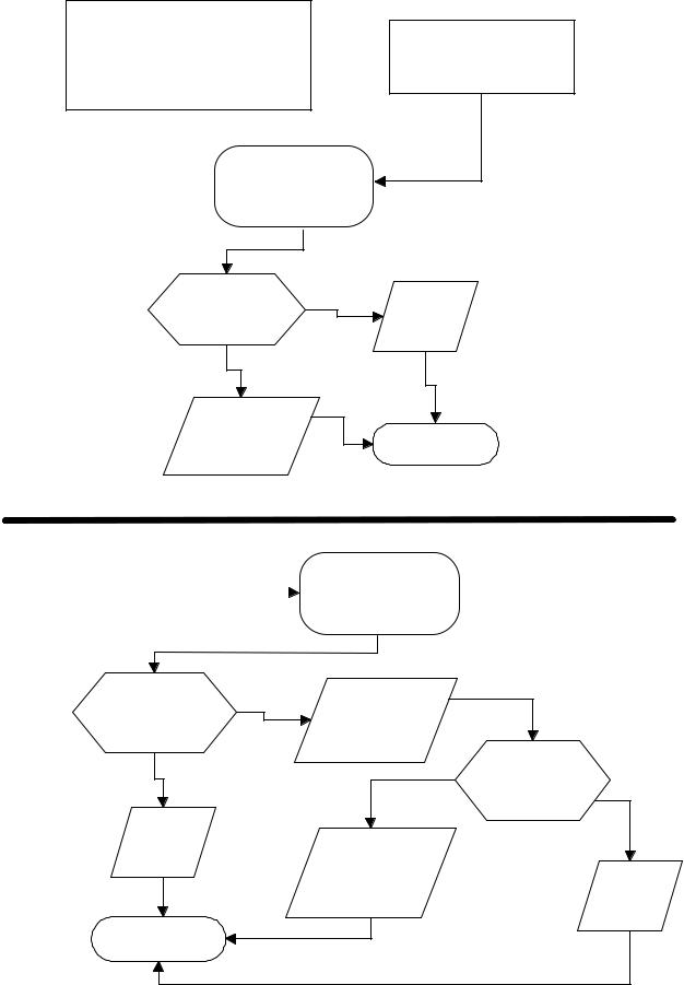
Troubleshooting Procedures
"PLEASE TOUCH TIME OF DAY" does not appear in
the display, when unit is plugged in.
1. Check power supply.  2. Check fuse.
3. Check oven thermostat.
Measure voltage between pin 1 and pin 3 of CN1 connector
|
YES |
|
Is 120 volts |
Replace |
|
indicated. |
circuit |
|
|
board. |
|
NO |
|
|
Verify proper |
|
|
connection of |
Unit operates. |
|
circuit board. |
||
|
Display does not |
|
Measure resistance |
indicate correct number |
|
|
|
of control key |
|
pressed or correct |
|
|
|
||
|
panel after removing |
|
indication when |
|
|
|
ribbon connector. |
|
programmed. |
|
|
|
|
|
|
|
|
Key pad matrix is located in “Testing Procedures” on page 11.
Is continuity |
|
Verify proper |
|
indicated when |
|
|
|
|
connection of |
|
|
key pad is |
|
|
|
YES |
ribbon |
|
|
pressed. |
|
||
|
connector. |
|
|
|
|
Does ribbon |
|
NO |
|
|
|
|
|
connector have |
|
|
|
NO |
|
|
|
proper |
|
|
|
|
connection. |
Replace |
|
|
YES |
control |
|
Reconnect |
|
key pad. |
|
|
|
|
ribbon connector |
|
|
|
|
for proper |
Replace |
|
|
connection. |
circuit |
|
|
|
board. |
Unit operates. |
|
|
|
©2002 Maytag Appliances Company |
13 |
16021668 Rev. 0 |
 Loading...