


User’s Manual
LG Programmable Logic Controller
MASTER-K 120S series
LG Industrial Systems
-When using LGIS equipment, thoroughly read this datasheet and associated manuals introduced in this datasheet. Also pay careful attention to safety and handle the module properly.
-Keep this datasheet within easy reach for quick reference

SAFETY INSTRUCTIONS
To Prevent injury and property damage, follow these instructions. Incorrect operation due to ignoring instructions will cause harm or damage, the seriousness of which is indicated by the following symbols.
 WARNING
 CAUTION
This symbol indicates the possibility of death or serious injury
This symbol indicates the possibility of injury or damage to property.
■ The meaning of each symbol in this manual and on your equipment is as follows
This is the safety alert symbol.
Read and follow instructions carefully to avoid dangerous situation.
.
This symbol alerts the user to the presence of “dangerous voltage” inside the product that might cause harm or electric shock.

SAFETY INSTRUCTIONS
Design Precautions
 Warning
Install a safety circuit external to the PLC that keeps the entire system safe even when there are problems with the external power supply or the PLC module. Otherwise, serious trouble could result from erroneous output or erroneous operation.
-Outside the PLC, construct mechanical damage preventing interlock circuits such as emergency stop, protective circuits, positioning upper and lower limits switches and interlocking forward/reverse operation.
When the PLC detects the following problems, it will stop calculation and turn off all output in the case of watchdog timer error, module interface error, or other hardware errors.
However, one or more outputs could be turned on when there are problems that the PLC CPU cannot detect, such as malfunction of output device (relay, transistor, etc.) itself or I/O controller. Build a fail safe circuit exterior to the PLC that will make sure the equipment operates safely at such times. Also, build an external monitoring circuit that will monitor any single outputs that could cause serious trouble.
Make sure all external load connected to output does NOT exceed the rating of output module.
Overcurrent exceeding the rating of output module could cause fire, damage or erroneous operation.
Build a circuit that turns on the external power supply when the PLC main module power is turned on.
If the external power supply is turned on first, it could result in erroneous output or erroneous operation.

SAFETY INSTRUCTIONS
Design Precautions
 Caution
Do not bunch the control wires or communication cables with the main circuit or power wires, or install them close to each other. They should be installed 100mm (3.94inch) or more from each other.
Not doing so could result in noise that would cause erroneous operation.
Installation Precautions
 Caution
Use the PLC in an environment that meets the general specification contained in this manual or datasheet.
Using the PLC in an environment outside the range of the general specifications could result in electric shock, fire, erroneous operation, and damage to or deterioration of the product.
Completely turn off the power supply before loading or unloading the module.
Not doing so could result in electric shock or damage to the product.
Make sure all modules are loaded correctly and securely.
Not doing so could cause a malfunction, failure or drop.
Make sure I/O and extension connector are installed correctly.
Poor connection could cause an input or output failure.
When install the PLC in environment of much vibration, be sure to insulate the PLC from direct vibration.
Not doing so could cause electric shock, fire, and erroneous operation.
Be sure to there are no foreign substances such as conductive debris inside the module.
Conductive debris could cause fires, damage, or erroneous operation.

SAFETY INSTRUCTIONS
Wiring Precautions
Warning
Completely turn off the external power supply when installing or placing wiring.
Not doing so could cause electric shock or damage to the product.
Make sure that all terminal covers are correctly attached.
Not attaching the terminal cover could result in electric shock.
 Caution
Be sure that wiring is done correctly be checking the product’s rated voltage and the terminal layout.
Incorrect wiring could result in fire, damage, or erroneous operation.
Tighten the terminal screws with the specified torque.
If the terminal screws are loose, it could result in short circuits, fire, or erroneous operation.
Be sure to ground the FG or LG terminal to the protective ground conductor.
Not doing so could result in erroneous operation.
Be sure there are no foreign substances such as sawdust or wiring debris inside the module.
Such debris could cause fire, damage, or erroneous operation.

SAFETY INSTRUCTIONS
Startup and Maintenance Precautions
 Warning
Do not touch the terminals while power is on.
Doing so could cause electric shock or erroneous operation.
Switch all phases of the external power supply off when cleaning the module or retightening the terminal or module mounting screws.
Not doing so could result in electric shock or erroneous operation.
Do not charge, disassemble, heat, place in fire, short circuit, or solder the battery.
Mishandling of battery can cause overheating or cracks which could result in injury and fires.
 Caution
Do not disassemble or modify the modules.
Doing so could cause trouble, erroneous operation, injury, or fire.
Switch all phases of the external power supply off before mounting or removing the module.
Not doing so could cause failure or malfunction of the module.
Use a cellular phone or walky-talky more than 30cm (11.81 inch) away from the PLC
Not doing so can cause a malfunction.
Disposal Precaution
 Caution
When disposing of this product, treat it as industrial waste.
Not doing so could cause poisonous pollution or explosion.

|
|
Revision History |
|
|
|
Date |
Code |
Revision history |
|
|
|
2002.7. |
10310000380 |
First edition is published |
|
|
|
2003.5. |
10310000380 |
A revised edition is published |
|
|
– Main unit and expansion modules are added |
|
|
– Built-in function are upgraded |
|
|
|
2003.9 |
10310000380 |
A revised edition is published. |
|
|
- Main units are added |
|
|
- Built-in functions are upgraded. |
|
|
|
|
|
|

Contents
Chapter 1. General
1.1Guide to Use This Manual ················· 1 - 1
1.2Features ······················· 1 - 2
1.3Terminology ······················ 1 - 3
Chapter 2. System Configuration
2.1Overall Configuration ··················· 2 - 1
2.1.1Basic System································································································ 2 - 1
2.1.2Cnet I/F System····························································································· 2 - 2
2.2Product Functional Model ················· 2 - 4
2.2.1Product Functional Block ················································································· 2 - 4
2.2.2MASTER-K120S Series System Equipment Product ············································· 2 - 5
Chapter 3. General Specifications
3.1 General Specifications ·················· 3 - 1
Chapter 4. Names of Parts
4.1Main Unit ······················· 4 - 1
4.1.160 Points Main Unit (Standard) ········································································· 4 - 2
4.1.240 Points Main Unit (Standard) ·········································································· 4 -3
4.1.330 Points Main Unit (Standard) ········································································· 4 - 4
4.1.420 Points Main Unit (Standard) ········································································· 4 - 5
4.1.530 Points Main Unit (Economic) ········································································ 4 - 6
4.1.620 Points Main Unit (Economic) ········································································· 4 -7
4.1.714 Points Main Unit (Economic) ········································································ 4 - 7
4.1.810 Points Main Unit (Economic) ········································································ 4 - 7
4.2Expansion I/O Module ··················· 4 - 8
4.2.120 Point I/O Module························································································ 4 - 8
4.2.210 Point I/O Module························································································ 4 - 8
4.2.38 Point I/O Module ························································································· 4 - 9
4.3 Special Module ···················· 4 - 10
4.3.1A/D·D/A Combination Module········································································4 - 10
4.3.2D/A Conversion Module··················································································4 - 11
4.3.3A/D Conversion Module··················································································4 - 11
4.3.4Analog Timer Module ·····················································································4 - 12
4.3.5RTD Input Module·························································································4 - 12

4.4Communication I/F Module ················· 4 - 13
4.4.1Cnet I/F Module····························································································4 - 13
4.4.2Fnet I/F Module ····························································································4 - 13
4.4.3Pnet I/F Module ····························································································4 - 14
4.4.4DeviceNet I/F Module ····················································································4 - 14
4.5Option Module ····················· 4 - 14
Chapter 5. Power Supply / CPU
5.1Power Supply Specifications ················ 5 - 1
5.1.1Standard Type······························································································· 5 - 1
5.3.2Economic Type······························································································ 5 - 1
5.2CPU Specifications ···················· 5 - 2
5.2.1Standard Type······························································································· 5 - 2
5.2.2Economic Type······························································································ 5 - 4
5.3 Operation Processing ··················· 5 -6
5.3.1Operation Processing Method··········································································· 5 - 6
5.3.2Operation Processing at Momentary Power Failure Occurrence ······························· 5 - 7
5.3.3Scan Time···································································································· 5 - 8
5.3.4Scan Watchdog Timer····················································································· 5 - 8
5.3.5 Timer Processing ························································································· 5 - 9
5.3.6Counter Processing·······················································································5 - 12
5.4Program························································································ 5 - 14
5.4.1Classifications of Program ·············································································5 - 14
5.4.2Program Execution Procedure ·········································································5 - 14
5.4.3Interrupt Programs ························································································5 - 15
5.4.4Error Handling······························································································5 - 17
5.5Operation Modes ···················· 5 - 19
5.5.1RUN Mode ··································································································5 - 19
5.5.2STOP Mode·································································································5 - 20
5.5.3PAUSE Mode·······························································································5 - 20
5.5.4DEBUG Mode(Standard Type Only)··································································5 - 20
5.5.5Operation Mode Change ················································································5 - 21
5.6Function························ 5 - 23
5.6.1Self-diagnosis ······························································································5 - 23
5.6.2I/O Force On/Off function ··············································································5 - 24
5.6.3Direct I/O Operation function ···········································································5 - 27
5.6.4System error history ······················································································5 - 27
5.7Memory Configuration ··················· 5 - 28
5.8I/O Address Allocation ··················· 5 - 29
5.9 Built-in Cnet Selection switch ··························································· 5 - 30 5.9.1 Structure·····································································································5 - 30

5.9.2Usage ········································································································5 - 30
5.10External Memory Module ················· 5 - 32
5.10.1Structure ···································································································5 - 32
5.10.2Usage·······································································································5 - 32
5.11RTC Module ······················ 5 - 34
5.11.1Structure ···································································································5 - 34
5.11.2Usage······································································································ 5 – 34
Chapter 6. Input and Output Modules
6.1Input / Output Specifications ················ 6 - 1
6.2Digital Input Specifications ················· 6 - 2
6.2.1Main Unit ····································································································· 6 - 2
6.2.2Expansion Module ························································································· 6 - 5
6.3Digital Output Specification ················· 6 - 6
6.3.1Main Unit (Relay Output) ················································································· 6 - 6
6.3.2Main Unit (Tr Output :DRT/DT Type Only) ··························································· 6 - 9
6.3.3Expansion Module ························································································6 - 11
Chapter 7. Usage of Various Functions
7.1Built-in Functions ···················· 7 - 1
7.1.1High Speed Counter Function··········································································· 7 - 1
7.1.2Pulse Catch Function·····················································································7 - 14
7.1.3Input Filter Function·······················································································7 - 16
7.1.4External Interrupt Function··············································································7 - 17
7.1.5PID Control Function(Standard Type Only) ·························································7 - 19
7.2Special Module ····················· 7 - 39
7.2.1A/D·D/A Combination Module········································································7 - 40
7.2.2A/D Conversion Module··················································································7 - 49
7.2.3D/A Conversion Module··················································································7 - 55
7.2.4Analogue Timer ··························································································7 - 61
7.2.5RTD input Module ·······················································································7 - 63
7.3Positioning Function(DRT /DTtype only) ············ 7 - 69
7.3.1Specification ································································································7 - 69
7.3.2Positioning Function ······················································································7 - 72
7.3.3Positioning parameter and Operation Data ·························································7 - 85
7.3.4Instructions ································································································7 - 91
7.3.5 Flag list and Error code ·············································································· 7 - 100 7.3.6 Wiring with servo and stepping motor driver······················································ 7 - 104
Chapter 8. Communication Function
8.1Dedicated Protocol Communication ·············· 8 - 1
8.1.1Introduction ·································································································· 8 - 1
8.1.2System configuration method ··········································································· 8 - 2
8.1.3Frame Structure ···························································································· 8 - 5
8.1.4Lists of Commands ························································································ 8 - 7
8.1.5Data Type ···································································································· 8 - 8
8.1.6Execution of Commands ················································································· 8 - 9
8.1.7 1:1, 1:n Built-in Communication between MASTER-K120S’s ································8 - 28
8.1.8Error Codes·································································································8 - 38
8.2User Defined Protocol Communication ············· 8 - 39
8.2.1Introduction ·································································································8 - 39
8.2.2Parameter Setting ·························································································8 - 39
8.2.3Instruction ·································································································8 - 47
8.2.4 Example of usage ·······················································································8 - 48
8.3Modbus Protocol Communication ··············· 8 - 57
8.3.1Introduction ·································································································8 - 57
8.3.2Basic Specifications ······················································································8 - 57
8.3.3Parameter Setting ·························································································8 - 60
8.3.4Instruction and examples ··············································································8 - 62
8.4No Protocol Communication ················ 8 - 67
8.4.1Introduction ·································································································8 - 67
8.4.2Parameter Setting ·························································································8 - 68
8.4.3Instructions··································································································8 - 69
8.4.4Examples ··································································································8 - 71
8.5Remote Connection and Communication I/F module ········ 8 - 73
8.5.1Remote Connection·······················································································8 - 73
8.5.2Communication I/F Module ·············································································8 - 76
Chapter 9. Installation and Wiring
9.1Installation ······················· 9 - 1
9.1.1Installation Environment ·················································································· 9 - 1
9.1.2Handling Instructions ······················································································ 9 - 3
9.1.3Connection of Expansion Module ······································································ 9 - 6
9.2Wiring ························ 9 - 7
9.2.1Power Supply Wiring ······················································································ 9 - 7
9.2.2Input and Output Devices Wiring ······································································· 9 - 8
9.2.3Grounding ···································································································· 9 - 9
9.2.4Cable Specifications for wiring ·········································································· 9 - 9

Chapter 10. Maintenance
10.1Maintenance and Inspection ················ 10 - 1
10.2Daily Inspection ···················· 10 - 1
10.3Periodic Inspection ··················· 10 - 2
Chapter 11. Troubleshooting
11.1Basic Procedure of Troubleshooting ············· 11 - 1
11.2Troubleshooting ············································································ 11 - 1
11.2.1Troubleshooting flowchart used when the power LED turns off ·····························11 - 2
11.2.2Troubleshooting flowchart used when the error LED is flickering ····························11 - 3
11.2.3Troubleshooting flowchart used when the RUN LED turns off ································11 - 4
11.2.4Troubleshooting flowchart used when the I/O devices doesn’t operate normally ········11 - 5
11.2.5Troubleshooting flowchart used when a program can’t be written to the CPU ············11 - 7
11.3Troubleshooting Questionnaire ························································· 11 - 8
11.4Troubleshooting Examples······························································· 11 - 9
11.4.1Input circuit troubles and corrective actions ·······················································11 - 9
11.4.2Output circuit troubles and corrective actions··················································· 11 - 10
11.5Error code list ·············································································· 11 - 12
Appendix ··················································································································
Appendix 1 System Definitions·······························································App1-1
Appendix 2 Flag Lists···········································································App2-1
Appendix 3 Dimensions········································································App3-1

Chapter 1 General
Chapter 1. General
1.1 Guide to Use This Manual
This manual includes specifications, functions and handling instructions for the MASTER-K120S series PLC. This manual is divided up into chapters as follows:
|
No. |
|
|
Title |
|
|
Contents |
|
|
Chapter 1 |
|
|
General |
|
Describes configuration of this manual, unit's features and terminology. |
|
|
|
Chapter 2 |
|
|
System configuration |
|
|
Describes available units and system configurations in the MASTER-K120S series. |
|
|
|
|
|
|
|
|
|
|
|
Chapter 3 |
|
|
General Specification |
|
Describes general specifications of units used in the MASTER-K120S series. |
|
|
|
Chapter 4 |
|
|
Names of Parts |
|
Describes each kind of manufacturing goods, titles, and main functions |
|
|
|
Chapter 5 |
|
|
Power Supply / CPU |
|
|
|
|
|
Chapter 6 |
|
|
Input and Output |
|
|
Describes each kind of manufactured goods' usage |
|
|
Chapter 7 |
|
|
Usage of Various |
|
|
|
|
|
|
|
|
|
|
|
||
|
|
|
Functions |
|
|
|
|
|
|
|
|
|
|
|
|
|
|
|
Chapter 8 |
|
|
Communication Function |
|
Describes built-in communication functions |
|
|
|
|
|
|
|
|
|
|
|
|
Chapter 9 |
|
|
Installation and Wiring |
|
|
Describes installation, wiring and handling instructions for reliability of the PLC system |
|
|
|
|
|
|
|
|
|
|
|
Chapter 10 |
|
|
Maintenance |
|
|
Describes the check items and method for long-term normal operation of the PLC |
|
|
|
|
|
|
system. |
|
||
|
|
|
|
|
|
|
|
|
|
Chapter 11 |
|
|
Troubleshooting |
|
|
Describes various operation errors and corrective actions. |
|
|
Appendix 1 |
|
|
System Definitions |
|
|
Describes parameter setting for basic I/O and communications module |
|
|
Appendix 2 |
|
|
Flag List |
|
|
Describes the types and contents of various flags. |
|
|
Appendix 3 |
|
|
Dimensions |
|
Shows dimensions of the main units and expansion modules |
|
|
REMARK
-. This manual does not describes the programming method. For their own functions, refer to the related user's manuals.
1-1

Chapter 1 General
1.2.Features
1)MASTER-K120S series is extremely compact, to fit a wide range of applications and have following features.
(1)High speed processing
High speed processing of 0.1~0.9 s/step with an general purpose processor included .
(2)Various built-in functions
The main unit can perform many functions without using separate modules. Therefore, It is possible to construct various systems just using the main unit.
•Fast Processing Applications
-Pulse catch: Allows the main unit to read a pulse which has width as small as 10 .
-High speed counter(Economic): Support high-speed counting up to 100(10)kHz for 1 phase, 50(5)kHz for 2 phase.
-External interrupts : Using in applications that have a high-priority event which requires immediate responses.
•The input filter function help reduce the possibility of false input conditions from external noise, such as signal chattering. The filter time can be programmed from 0 to 1000ms.
•Using RS-232C and RS-485 built-in port, MASTER-K120S can connects with external devices, such as personal computers or monitoring devices and communicate 1:N with MASTER-K120S system.
•Using built-in PID control function, PID control system can be constructed without using separate PID module.
•Using built-in Positioning function, position control system can be constructed without using separate position control module.(only DRT/DT type has built-in positioning function)
(3)Battery-less
The user’s program can be saved permanently, because it is stored to EEPROM.
(4)When program is edited during processing, it is stored to EEPROM automatically
(5)Open network by use of communication protocols in compliance with international standard specifications.
(6)Various special modules that enlarge the range of application of the PLC
(7)It can easily do On/Off of the system, using RUN/STOP switch.
(8)It can easily save the user program in EEPROM by simple manipulation in KGLWIN without using external memory.
(9)Strong self-diagnostic functions
It can detect the cause of errors with more detailed error codes.
(10)It can prevent unintentional reading and writing, using password.
(11)Debugging function(Standard type)
On-line debugging is available when the PLC Operation mode is set to debug mode.
yexecuted by one command.
yexecuted by break-point settings.
yexecuted by the condition of the device
yexecuted by the specified scan time.
(12)Various program execution function
External and internal interrupt program as well as scan program can be executed by setting the execution condition. Therefore, user can set variously program execution mode.
1-2

Chapter 1 General
1.3 Terminology
The following table gives definition of terms used in this manual.
|
Terms |
|
|
Definition |
|
|
|
|
Remarks |
|
|
|
|
|
|
|
|
|
|
|
|
|
|
|
|
A standard element that has a specified function which configures |
the |
|
|
Example) |
|
|
|
|
|
|
|
|
CPU module |
|
|||
|
Module |
|
|
system. Devices such as I/O board, which inserted onto the mother board |
|
|
|
|||
|
|
|
|
|
Power Supply module |
|
||||
|
|
|
|
or base unit. |
|
|
|
|
|
|
|
|
|
|
|
|
|
|
I/O module |
|
|
|
|
|
|
|
|
|
|
|
|
|
|
Unit |
|
|
A single module or group of modules that perform an independent |
|
|
|
|
Example) |
|
|
|
|
Operation as a part of PLC system. |
|
|
|
|
Main unit |
|
|
|
|
|
|
|
|
|
|
|
||
|
|
|
|
|
|
|
|
|
||
|
PLC system |
|
|
A system which consists of the PLC and peripheral devices. A user program |
|
|
|
|
||
|
|
|
can control the system. |
|
|
|
|
|
|
|
|
|
|
|
|
|
|
|
|
|
|
|
|
|
|
|
|
|
|
|
||
|
KGLWIN |
|
|
A program and debugging tool for the MASTER-K series. It executes |
|
|
|
|
||
|
|
|
program creation, edit, compile and debugging(A computer software). |
|
|
|
|
|
|
|
|
|
|
|
|
|
|
|
|
|
|
|
|
|
|
|
|
|
|
|
||
|
KLD-150S |
|
|
A hand-held loader used for program creation, edit, compile and debugging |
|
|
|
|
||
|
|
|
for MASTER-K series. |
|
|
|
|
|
|
|
|
|
|
|
|
|
|
|
|
|
|
|
|
|
|
|
|
|
|
|
||
|
I/O Image Area |
|
Internal memory area of the CPU module which used to hold I/O statuses. |
|
|
|
|
|
||
|
|
|
|
|
|
|
|
|
|
|
|
Watch Dog Timer |
|
|
Supervisors the pre-set execution times of programs and warns |
if |
a |
|
|
|
|
|
|
|
program is not completed within the pre-set time. |
|
|
|
|
|
|
|
|
|
|
|
|
|
|
|
|
|
|
|
|
|
|
|
|
|
|
|
||
|
FAM |
|
|
Abbreviation of the word ‘Factory Automation Monitoring S/W’. It is used to |
|
|
|
|
||
|
|
|
call S/W packages for process supervision. |
|
|
|
|
|
|
|
|
|
|
|
|
|
|
|
|
|
|
|
|
|
|
|
|
|
|
|
|
|
|
Fnet |
|
Fieldbus network |
|
|
|
|
|
|
|
|
|
|
|
|
|
|
|
|
|
|
|
Cnet |
|
|
Computer network(RS-232C, RS-422/485) |
|
|
|
|
|
|
|
|
|
|
|
|
|
|
|
|
|
|
RTC |
|
|
Abbreviation of ‘Real Time Clock’. It is used to call general IC that |
|
|
|
|
|
|
|
|
|
contains clock function. |
|
|
|
|
|
|
|
|
|
|
|
|
|
|
|
|
|
|
|
|
|
|
|
|
|
|
|
|
|
1-3
Chapter 1 General
Terms |
|
|
|
Definition |
Remarks |
|
|
|
|
|
|
|
Current flows from the switch to the PLC input terminal if a input signal turns on. |
|
|||
Sink Input |
|
|
|
|
|
|
|
|
|
|
|
|
Current flows from the PLC input terminal to the switch after a input signal turns |
|
|||
|
on. |
|
|||
Source |
|
|
|
|
|
Input |
|
|
|
|
|
|
|
|
|
|
|
|
Current flows from the load to the output terminal and the PLC output turn on. |
|
|||
|
|
|
|
|
|
Sink Output |
|
|
Output |
|
|
|
|
|
Contact |
|
|
|
|
|
|
|
|
|
|
|
|
|
|
|
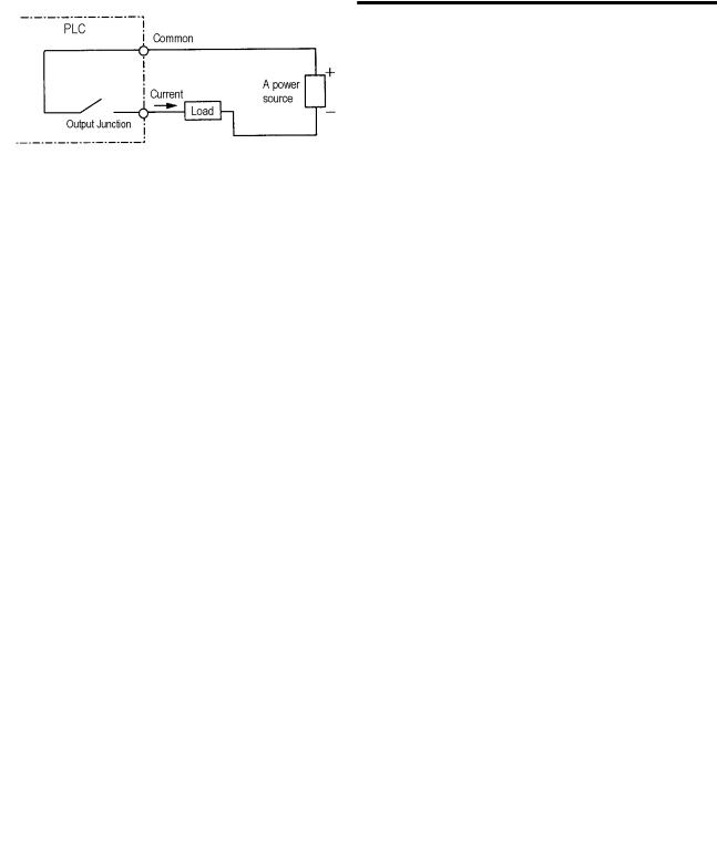
Current flows from the output terminal to the load and the PLC output turn on. |
|
|||
Source |
|
|
|
|
|
Output |
|
|
|
|
|
|
|
|
|
||
|
|
Output Contact |
|
|
|
|
|
|
|
|
|
1-4
Chapter 2 System Configuration
Chapter 2. System Configuration
The MASTER-K120S series has suitable to configuration of the basic, computer link and network systems. This chapter describes the configuration and features of each system.
2.1Overall Configuration
2.1.1Basic system
|
|
|
|
|
|
|
|
|
|
|
|
|
|
|
|
expansion |
||||||
|
|
|
|
Main unit |
|
|
|
|
|
|
|
|
|
|
||||||||
|
|
|
|
|
|
|
|
|
module |
|||||||||||||
|
|
|
|
|
|
|
|
|
|
|
|
|
|
|
|
|||||||
|
|
|
|
|
|
|
|
|
|
|
|
|
|
|
|
|
|
|
|
|
|
|
|
|
|
|
|
|
|
|
|
|
|
|
|
|
|
|
|
|
|
|
|
|
|
|
|
|
|
|
|
|
|
|
|
|
|
|
|
|
|
|
|
|
|
|
|
|
|
|
|
|
|
|
|
|
|
|
|
|
|
|
|
|
|
|
|
|
|
|
|
|
|
|
|
|
|
|
|
|
|
|
|
|
|
|
|
|
|
|
|
|
|
|
|
|
|
|
|
|
|
|
|
|
|
|
|
|
|
|
|
|
|
|
|
|
|
|
|
|
|
|
|
|
|
|
|
|
|
|
|
|
|
|
|
|
|
|
|
|
|
|
|
|
|
|
|
|
|
|
|
|
|
|
|
|
|
|
|
|
|
|
|
|
|
|
|
|
|
|
|
|
|
|
|
|
|
|
|
|
|
|
|
|
|
|
|
|
|
|
|
|
|
|
|
|
|
|
|
|
|
|
|
|
|
|
|
|
|
|
|
|
|
|
|
|
|
|
|
|
|
|
|
|
|
|
|
|
|
|
|
|
|
|
|
|
|
|
|
|
|
|
|
|
|
|
|
|
|
|
|
|
|
|
|
expansion cable
Total I/O points |
|
• 10-120 points |
|
||
|
|
Digital I/O module |
Standard |
Economic |
|
Maximum number |
• 3 modules |
• 2 modules |
|||
|
|||||
A/D-D/A module |
• 3 modules |
• 2 modules |
|||
of expansion |
|||||
Analog timer |
• 3 modules |
• 2 modules |
|||
modules |
|||||
|
|
|
|
|
|
|
|
Cnet I/F module |
• 1 module |
• 1 modules |
|
|
Main unit |
Economic |
• K7M-DR10/14/20/30UE |
|
|
|
Standard |
• K7M-DR//DRT/DT20/30/40/60U |
|
||
|
|
|
|||
|
|
Digital I/O module |
• G7E-DR10A, G7E-DR20A, G7E-TR10A, G7E-DC08A, G7E-RY08A |
||
|
Expansion |
Analog I/O module |
• G7F-ADHA, G7F-ADHB, G7F-AD2A, G7F-DA2I, G7F-DA2V |
||
|
module |
Analog timer |
• G7F-AT2A |
|
|
Items |
|
Resistance Temperature Detactor |
• G7F-RD2A |
|
|
Communic |
Cnet I/F modules |
• G7L-CUEB, G7L-CUEC |
|
||
|
|
||||
|
DeviceNet I/F module |
• G7L-DBEA |
|
||
|
ation I/F |
|
|||
|
FieldBus I/F module |
• G7L-FUEA |
|
||
|
module |
|
|||
|
Profibus I/F Module |
• G7L-PBEA |
|
||
|
|
|
|||
|
Option |
RTC |
• G7E-RTCA |
|
|
|
module |
Memory |
• G7M-M256B |
|
|
2-1
Chapter 2 System Configuration
2.1.2 Cnet I/F system
Cnet I/F System is used for communication between the main unit and external devices using RS-232C/RS-422 Interface. The MK120S has a built-in RS-232C port, RS-485 port and has also G7L-CUEB for RS-232C, G7L-CUEC for RS-422. It is possible to construct communication systems on demand.
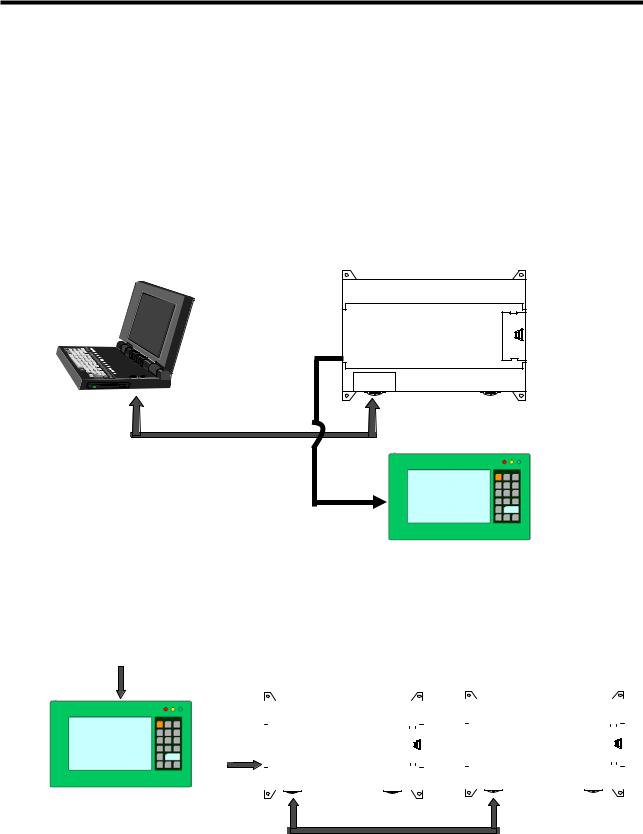
1)1:1 Communications system
(1)1:1 ratio of an external device (computer) to main unit using a built-in port
MASTER-K120S
RS-232C
Monitoring Device
RS-485
(2) 1:1 ratio of an external device (monitoring unit) to main unit using a built-in RS-485 port
RS-485
|
|
|
|
MASTER-K120S |
|
|
MASTER-K120S |
|||||||||||||
|
|
|
|
|
|
|||||||||||||||
|
|
|
|
|
|
|
|
|
|
|
|
|
|
|
|
|
|
|
|
|
|
|
|
|
|
|
|
|
|
|
|
|
|
|
|
|
|
|
|
|
|
|
|
|
|
|
|
|
|
|
|
|
|
|
|
|
|
|
|
|
|
|
|
|
|
|
|
|
|
|
|
|
|
|
|
|
|
|
|
|
|
|
|
|
|
|
|
|
|
|
|
|
|
|
|
|
|
|
|
|
|
|
|
|
|
|
|
|
|
|
|
|
|
|
|
|
|
|
|
|
|
|
|
|
|
|
|
|
|
|
|
|
|
|
|
|
|
|
|
|
|
|
|
|
|
|
|
|
|
|
|
|
|
|
|
|
|
|
|
|
|
|
|
|
|
|
|
Monitoring Device
RS-232C
2-2
Chapter 2 System Configuration
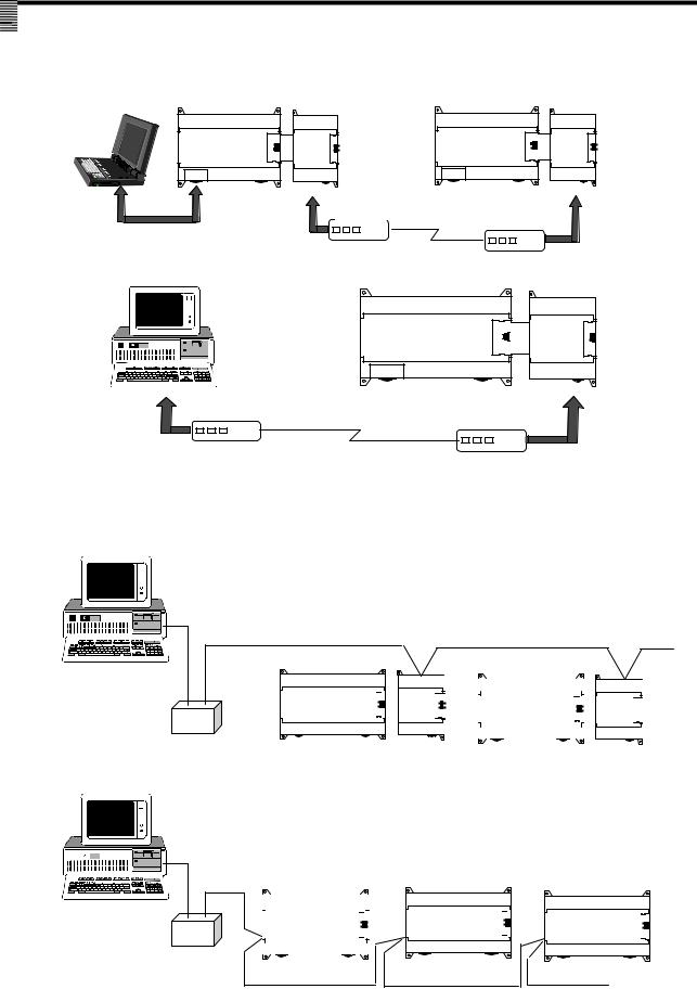
(3) RS-232C Communication over a long distance via modem by Cnet I/F modules
MASTER-K120S G7L-CUEB MASTER-K120S G7L-CUEB
Modem |
Modem |
|
MASTER-K120S G7L-CUEB
Modem |
Modem |
|
2) 1:n Communications system
This method can connect between one computer and multiple main units for up to 32 stations
Can be connected Max. 32 stations
RS-232C RS-422 Converter |
|
|
|
|
|
|
|
|
|
|
|
|
|
|
|
|
|
|
|
|
|
|
|
|
|
|
||
|
|
|
|
|
|
|
|
|
|
|
|
|
|
|
|
|
|
|
|
|
|
|
|
|
|
|||
|
|
|
|
|
|
|
|
|
|
|
|
|
|
|
|
|
|
|
|
|
|
|
|
|
|
|||
|
|
|
|
|
|
|
|
|
|
|
|
|
|
|
|
|
|
|
|
|
|
|
|
|
|
|||
|
|
|
|
|
|
|
G7L-CUEC |
|
|
|
|
|
|
|
|
|
|
G7L-CUEC |
||||||||||
|
|
|
|
|
|
|
|
|
|
|
|
|
|
|
|
|
|
|
|
|
|
|
|
|
|
|
|
|
|
|
|
|
|
|
|
|
|
|
|
|
|
|
|
|
|
|
|
|
|
|
|
|
|
|
|
|
|
|
|
|
|
|
|
|
|
|
|
|
|
|
|
|
|
|
|
|
|
|
|
|
|
|
|
|
|
|
|
|
|
|
|
|
|
MASTER-K120S |
|
MASTER-K120S |
|
|
|
|
MASTER-K120S |
|
|||||||
|
|
|
|
|
|
|
|
|
|
|
|
|
||||||||||
|
|
|
|
|
|
|||||||||||||||||
|
|
|
|
|
|
|
|
|
|
|
|
|
|
|
|
|
|
|
|
|
|
|
|
|
|
|
|
|
|
|
|
|
|
|
|
|
|
|
|
|
|
|
|
|
|
|
|
|
|
|
|
|
|
|
|
|
|
|
|
|
|
|
|
|
|
|
|
|
|
|
|
|
|
|
|
|
|
|
|
|
|
|
|
|
|
|
|
|
|
|
|
|
|
|
|
|
|
|
|
|
|
|
|
|
|
|
|
|
|
|
|
|
|
|
RS-232C RS-485
Converter
Built-in RS-485 |
Built-in RS-485 |
Built-in RS-485 |
* Refer to ‘chapter 8. communication function’ for details.
2-3
Chapter 2 System Configuration
2.2 Product Functional Model
The following describes functional model of the MASTER-K120Sseries.
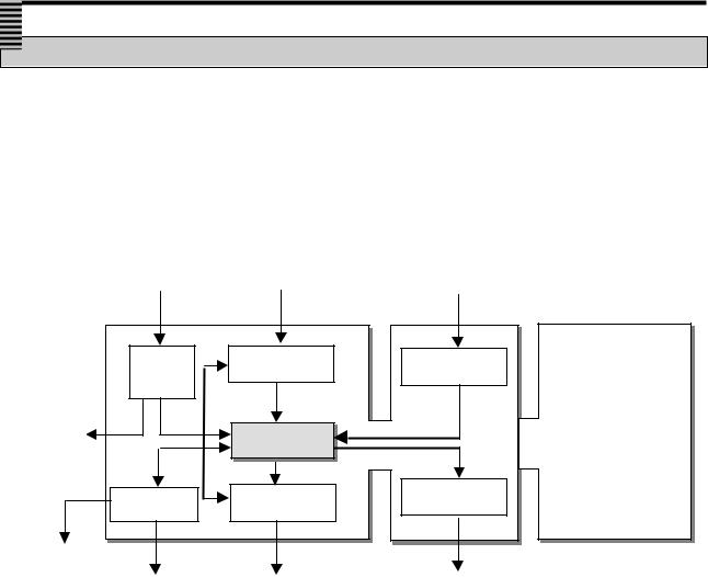
2.2.1 Product Functional Block
Product function block for the K120S series is as follows.
Main Unit |
Expansion Modules |
|
Power supply |
Input signal |
Input signal |
|
|
Power |
Input |
Input |
|
|
supply |
|||
|
|
|
||
DC24V |
|
|
Special/communication |
|
Power |
• |
CPU |
||
supply |
modules |
|||
|
||||
|
|
|
||
|
Comm. I/F |
Output |
Output |
|
|
|
|||
Built-in |
|
|
|
|
RS-485 |
|
|
|
|
|
Built-in RS-232C I/F |
Output signal |
Output signal |
Sub-system |
Description |
CPU |
• Signal processing function |
|
-. Operating system function |
|
-. Application program storage / memory function |
|
-. Data storage / memory function |
|
-. Application program execution function |
Input |
• The input signals obtained from the machine/process to appropriate signal levels for |
|
processing |
Output |
• The output signals obtained from the signal processing function to appropriate signal |
|
levels to drive actuators and/or displays |
Power Supply |
• Provides for conversion and isolation of the PLC system power from the main supply |
Communication |
• Provides the data exchange with other systems or PADT, such as KGLWIN, personal |
Interface |
computers |
2-4
Chapter 2 System Configuration
2.2.2K120S Series System Equipment Product
1)Main Unit – Standard type
|
Items |
|
|
Models |
|
|
I/O Point & |
|
|
Built-in Function |
|
|
Remark |
|
|
|
|
|
|
Power Supply |
|
|
|
|
|
||||
|
|
|
|
|
|
|
|
|
|
|
|
|
|
|
|
|
|
|
K7M-DR20U |
|
12 DC inputs(24VDC) |
|
|
• Program capacity : 10 k steps |
|
|
|
|
|
|
|
|
|
|
8 relay outputs |
|
|
|
|
|
|
|||
|
|
|
|
|
|
|
• Max. expansion : 3 modules |
|
|
|
|
|||
|
|
|
|
|
|
85~264 VAC |
|
|
|
|
|
|
||
|
|
|
|
|
|
|
|
• High-speed counter : |
|
|
|
|
||
|
|
|
|
|
|
|
|
|
|
|
|
|
|
|
|
|
|
|
|
|
18 DC inputs(24VDC) |
|
|
|
|
|
|
||
|
|
|
|
K7M-DR30U |
|
|
|
- 1 Phase : 100 kHz 1channel, 20 kHz 2channel. |
|
|
|
|
||
|
|
|
|
|
12 relay outputs |
|
|
|
|
|
|
|||
|
|
|
|
|
|
85~264 VAC |
|
|
- 2 Phase : 50 kHz 1channel, 10 kHz 1channel. |
|
|
|
|
|
|
|
|
|
K7M-DR40U |
|
24 DC inputs(24VDC) |
|
|
• Pulse catch : pulse width 10 2 points, 50 6 points, |
|
|
|
|
|
|
|
|
|
|
16 relay outputs |
|
|
• External interrupt: : 10 2 points, 50 6 points |
|
|
|
|
||
|
|
|
|
|
|
85~264 VAC |
|
|
• Input filter: 0 ~ 1000ms (can be designated with groups) |
|
|
|
|
|
|
|
|
|
K7M-DR60U |
|
36 DC inputs(24VDC) |
|
|
• PID control function |
|
|
|
|
|
|
|
|
|
|
24 relay outputs |
|
|
• RS-232C communication, RS-485 communication |
|
|
|
|
||
|
|
|
|
|
|
85~264 VAC |
|
|
|
|
|
|
||
|
|
|
|
|
|
|
|
|
|
|
|
|
||
|
|
|
|
K7M- |
|
12 DC inputs(24VDC) |
|
|
• Program capacity : 10 k steps |
|
|
|
|
|
|
|
|
|
|
4/0 relay outputs |
|
|
• Max. expansion : 3 modules |
|
|
|
|
||
|
Main Unit |
|
|
DRT/DT20U |
|
4/8 TR outputs |
|
|
|
|
|
|
||
|
|
|
|
|
|
• High-speed counter : |
|
|
|
|
||||
|
|
|
|
|
85~264 VAC |
|
|
|
|
|
|
|||
|
|
|
|
|
|
|
|
- 1 Phase : 100 kHz 1channel, 20 kHz 2channel. |
|
|
|
|
||
|
|
|
|
|
|
18 DC inputs(24VDC) |
|
|
|
|
|
|
||
|
|
|
|
K7M- |
|
|
|
- 2 Phase : 50 kHz 1channel, 10 kHz 1channel. |
|
|
|
|
||
|
|
|
|
|
8/0 relay outputs |
|
|
|
|
|
|
|||
|
|
|
|
DRT/DT30U |
|
4/12 TR outputs |
|
|
• Pulse catch : pulse width 10 - 2 points, 50 - 6 points, |
|
|
|
|
|
|
|
|
|
|
|
85~264 VAC |
|
|
• External interrupt: : 10 - 2 points, 50 - 6 points |
|
|
|
|
|
|
|
|
|
K7M- |
|
24 DC inputs(24VDC) |
|
|
• Input filter: 0 ~ 1000ms (can be designated with groups) |
|
|
|
|
|
|
|
|
|
|
12/0 relay outputs |
|
|
• PID control function |
|
|
|
|
||
|
|
|
|
DRT/DT40U |
|
4/16 TR outputs |
|
|
|
|
|
|
||
|
|
|
|
|
|
|
• RS-232C communication, RS-485 communication |
|
|
|
|
|||
|
|
|
|
|
|
85~264 VAC |
|
|
|
|
|
|
||
|
|
|
|
|
|
|
|
• Positioning function |
|
|
|
|
||
|
|
|
|
|
|
|
|
|
|
|
|
|
|
|
|
|
|
|
|
|
36 DC inputs(24VDC) |
|
|
- 2axes 100 kpps |
|
|
|
|
|
|
|
|
|
K7M- |
|
|
|
- Absolute / Incremental positioning method |
|
|
|
|
||
|
|
|
|
|
20/0 relay outputs |
|
|
|
|
|
|
|||
|
|
|
|
DRT/DT60U |
|
4/24 TR outputs |
|
|
- Single / Repeat operation method |
|
|
|
|
|
|
|
|
|
|
|
85~264 VAC |
|
|
- End / Keep / Continuous mode |
|
|
|
|
|
|
|
|
|
|
|
|
|
|
|
- Return to origin, JOG, PWM, velocity control |
|
|
|
|
2) Main Unit – Economic type |
|
|
|
|
|
|
|
|||||||
|
|
|
|
|
|
|
|
|
|
|
|
|
|
|
|
Items |
|
|
Models |
|
|
I/O Point & |
|
|
Built-in Function |
|
|
Remark |
|
|
|
|
|
|
Power Supply |
|
|
|
|
|
||||
|
|
|
|
|
|
|
|
|
|
|
|
|
|
|
|
|
|
|
K7M-DR10UE |
|
6 DC inputs(24VDC) |
|
|
• Program capacity : 2 k steps |
|
|
|
|
|
|
|
|
|
|
4 relay outputs |
|
|
• Max. expansion : 2 modules |
|
|
|
|
||
|
|
|
|
|
|
85~264 VAC |
|
|
• Pulse catch : pulse width 50 4 points, |
|
|
|
|
|
|
|
|
|
K7M-DR14UE |
|
8 DC inputs(24VDC) |
|
|
• High-speed counter : |
|
|
|
|
|
|
|
|
|
|
6 relay outputs |
|
|
- 1 Phase : 10 kHz 2channel. |
|
|
|
|
||
|
Main Unit |
|
|
|
|
85~264 VAC |
|
|
|
|
|
|
||
|
|
|
|
|
|
|
- 2 Phase : 5 kHz 1channel. |
|
|
|
|
|||
|
|
|
|
|
12 DC inputs(24VDC) |
|
|
|
|
|
|
|||
|
|
|
|
K7M-DR20UE |
|
|
|
• External interrupt: : 50 4 points |
|
|
|
|
||
|
|
|
|
|
8 relay outputs |
|
|
|
|
|
|
|||
|
|
|
|
|
|
|
• Input filter: 0 ~ 1000ms (can be designated with groups) |
|
|
|
|
|||
|
|
|
|
|
|
85~264 VAC |
|
|
|
|
|
|
||
|
|
|
|
|
|
|
|
• RS-232C communication |
|
|
|
|
||
|
|
|
|
|
|
18 DC inputs(24VDC) |
|
|
|
|
|
|
||
|
|
|
|
K7M-DR30UE |
|
|
|
• RS-485 communication(K7M-DR10/14UE only) |
|
|
|
|
||
|
|
|
|
|
12 relay outputs |
|
|
|
|
|
|
|||
|
|
|
|
|
|
85~264 VAC |
|
|
• Built-in analog timer(K7M-DR10/14UE only) |
|
|
|
|
|
2-5

Chapter 2 System Configuration
3) Expansion Modules
|
Section |
|
|
Items |
|
|
Models |
|
|
Description |
|
|
|
Remark |
|
|
|
|
|
|
|
|
|
G7E-DR10A |
|
|
• 6 DC inputs / 4 relay outputs |
|
|
|
|
|
|
|
|
|
|
|
|
|
|
|
|
|
|
|
|
|
|
|
|
|
|
|
|
|
|
G7E-DR20A |
|
|
• 12 DC inputs / 8 relay outputs |
|
|
|
|
|
|
|
|
|
|
|
|
|
|
|
|
|
|
|
|
|
|
|
|
Expansion |
|
|
|
|
|
G7E-DC08A |
|
|
• 8 DC inputs |
|
|
Slim Type |
|
||
|
|
|
Digital I/O module |
|
|
|
|
|
|
|
|
|
|
|||
|
|
|
|
|
|
|
|
|
|
|
|
|
|
|
||
|
module |
|
|
|
|
|
|
|
|
|
|
|
|
|
|
|
|
|
|
|
|
G7E-TR10A |
|
|
• 10 Transistor outputs |
|
|
|
|
|
|
||
|
|
|
|
|
|
|
|
|
|
|
|
|
|
|||
|
|
|
|
|
|
|
|
|
|
|
|
|
|
|
||
|
|
|
|
|
|
|
|
|
|
|
|
|
|
|
|
|
|
|
|
|
|
|
|
G7E-RY08A |
|
|
• 8 relay outputs |
|
|
Slim Type |
|
||
|
|
|
|
|
|
|
|
|
|
|
|
|
|
|
||
|
|
|
|
|
|
|
|
|
|
|
|
|
|
|
|
|
|
|
|
|
|
|
|
G7E-DR08A |
|
|
• 4 DC Input, 4 Relay output |
|
|
|
|
|
|
|
|
|
|
|
|
|
|
|
|
|
|
|
|
|
|
|
|
|
|
|
A/D-D/A |
|
|
G7F-ADHA |
|
|
• A/D : 2 channel , D/A : 1 channel |
|
|
|
|
|
|
|
|
|
|
|
|
|
|
|
|
|
|
|
|
|
|
|
|
|
|
|
Combination module |
|
|
G7F-ADHB |
|
|
• A/D : 2 channel , D/A : 2 channel |
|
|
Slim |
|
|
|
|
|
|
|
|
|
|
|
|
|
|
Type |
|
|
|
||
|
|
|
|
|
|
|
|
|
|
|
|
|
|
|
|
|
|
|
|
|
A/D conversion module |
|
|
G7F-AD2A |
|
|
• A/D : 4 channel |
|
|
|
|
|
|
|
|
|
|
|
|
|
|
|
|
|
|
|
|
|
|
|
|
|
|
|
|
|
|
G7F-DA2I |
|
|
• D/A : 4 channel(current output) |
|
|
|
|
|
|
|
|
|
|
D/A conversion module |
|
|
|
|
|
|
|
|
|
|
|
|
|
|
|
|
|
|
G7F-DA2V |
|
|
• D/A : 4 channel(voltage output) |
|
|
Slim |
|
|
|
|
|
|
|
|
|
|
|
|
|
|
|
|
|
|
|||
|
|
|
|
|
|
|
|
|
|
|
Type |
|
|
|
||
|
|
|
|
|
|
|
|
|
|
|
|
|
|
|
|
|
|
|
|
|
Analog timermodule |
|
|
G7F-AT2A |
|
|
• Points : 4points |
|
|
|
|
|
|
|
|
|
|
|
|
|
|
• Digital output range : 0~200 |
|
|
|
|
|
|
||
|
|
|
|
|
|
|
|
|
|
|
|
|
|
|
|
|
|
Special |
|
|
RTD module |
|
|
G7F-RD2A |
|
|
• Resistance temperature detactor |
|
|
Slim |
|
Standard |
|
|
|
|
|
|
|
|
- 4 channel(Pt100, JPt100) |
|
|
Type |
|
type only |
|
|||
|
|
|
|
|
|
|
|
|
|
|
|
|
||||
|
module |
|
|
|
|
|
G7L-CUEB |
|
|
• RS-232C : 1 channel |
|
|
|
|
|
|
|
|
|
|
|
|
|
|
|
|
|
|
|
|
|
||
|
|
|
|
|
|
|
|
|
|
|
|
|
|
|
|
|
|
|
|
|
|
|
|
G7L-CUEC |
|
|
• RS-422 : 1 channel |
|
|
|
|
|
|
|
|
|
|
Communication I/F module |
|
|
|
|
|
|
|
|
|
|
|
|
|
|
|
|
|
|
G7L-DBEA |
|
|
• DeviceNet I/F module (Slave) |
|
|
|
|
|
|
|
|
|
|
|
|
|
|
|
|
|
|
|
|
|
|
Standard |
|
|
|
|
|
|
|
|
G7L-FUEA |
|
|
• FieldBus I/F module |
|
|
|
|
|
|
|
|
|
|
|
|
|
|
|
|
|
|
|
type only |
|
||
|
|
|
|
|
|
|
|
|
|
|
|
|
|
|
|
|
|
|
|
|
|
|
|
G7L-PBEA |
|
|
• Profibus I/F module (Slave) |
|
|
|
|
|
|
|
|
|
|
|
|
|
|
|
|
|
|
|
|
|
|
|
|
|
|
|
RTC module |
|
|
G7E-RTCA |
|
|
• Real Time Clock module |
|
|
|
|
|
|
|
|
|
|
|
|
|
|
|
|
|
|
|
|
|
|
|
|
|
|
|
External Memory |
|
|
G7M-M256B |
|
|
• External Memory module |
|
|
|
|
|
|
* External memory G7M-M256 isn’t supported in K120S series. Only G7M-M256B is available for K120S series.
2-6

Chapter 3 General Specifications
Chapter 3. General Specifications
3.1 General Specifications
The following table shows the general specifications of the MASTER-K120S series.
|
No. |
|
|
Item |
|
|
|
|
Specifications |
|
|
|
|
References |
|
|||
|
1 |
|
|
Operating ambient |
|
|
0 ~ 55 °C |
|
|
|
|
|
|
|
|
|
|
|
|
|
|
Temperature |
|
|
|
|
|
|
|
|
|
|
|
|
|
||
|
|
|
|
|
|
|
|
|
|
|
|
|
|
|
|
|
|
|
|
2 |
|
|
Storage ambient |
|
|
−25 ~ +70 °C |
|
|
|
|
|
|
|
|
|
|
|
|
|
|
Temperature |
|
|
|
|
|
|
|
|
|
|
|
|
|
||
|
|
|
|
|
|
|
|
|
|
|
|
|
|
|
|
|
|
|
|
|
|
|
|
|
|
|
|
|
|
|
|
|
|
|
|
|
|
|
3 |
|
|
Operating ambient |
|
|
5 ~ 95%RH, non-condensing |
|
|
|
|
|
|
|
|
|
|
|
|
|
|
Humidity |
|
|
|
|
|
|
|
|
|
|
|
|
|||
|
|
|
|
|
|
|
|
|
|
|
|
|
|
|
|
|
|
|
|
|
|
|
|
|
|
|
|
|
|
|
|
|
|
|
|
|
|
|
4 |
|
|
Storage ambient |
|
|
5 ~ 95%RH, non-condensing |
|
|
|
|
|
|
|
|
|
|
|
|
|
|
Humidity |
|
|
|
|
|
|
|
|
|
|
|
|
|||
|
|
|
|
|
|
|
|
|
|
|
|
|
|
|
|
|
|
|
|
|
|
|
|
|
|
|
|
|
|
|
|
- |
|
|
|
|
|
|
|
|
|
|
|
|
|
Occasional vibration |
|
|
|
|
|
|
||||
|
|
|
|
|
|
|
Frequency |
Acceleration |
|
Amplitude |
|
Sweep count |
|
|
|
|
||
|
|
|
|
|
|
|
10 ≤ f < 57Hz |
− |
|
|
0.075mm |
|
|
|
|
|
|
|
|
5 |
|
|
Vibrations |
|
|
57 ≤ f ≤ 150Hz |
9.8m/s2 {1G} |
|
|
− |
|
|
|
|
IEC 61131-2 |
|
|
|
|
|
|
|
|
Continuous vibration |
|
|
|
10 times for each |
|
|
|
|||||
|
|
|
|
|
|
|
|
|
|
|
|
|
|
|||||
|
|
|
|
|
|
|
Frequency |
Acceleration |
|
Amplitude |
|
X, Y, Z axis |
|
|
|
|
||
|
|
|
|
|
|
|
10 ≤ f < 57Hz |
− |
|
|
0.035mm |
|
|
|
|
|
|
|
|
|
|
|
|
|
|
57 ≤ f ≤ 150Hz |
4.9m/s2 {0.5G} |
|
|
− |
|
|
|
|
|
|
|
|
|
|
|
|
|
|
• Maximum shock acceleration: 147 m/s2 {15G} |
|
|
|
|
|
|
IEC 61131-2 |
|
|||
|
6 |
|
|
Shocks |
|
|
• Duration time: 11ms |
|
|
|
|
|
|
|
|
|
||
|
|
|
|
|
|
|
• Pulse wave: half sine pulse ( 3 shocks per axis, on X, Y, Z axis ) |
|
|
|
|
|
|
|||||
|
|
|
|
|
|
|
|
|
|
|
|
|
|
|
|
|
|
|
|
|
|
|
|
|
|
Square wave |
± 1,500 V |
|
|
|
|
|
|
|
|
LGIS’ Internal |
|
|
|
|
|
|
|
|
Impulse noise |
|
|
|
|
|
|
|
|
Standard |
|
|
|
|
|
|
|
|
|
|
|
|
|
|
|
|
|
|
|
|
|
|
|
|
|
|
|
|
Electronic |
Voltage: 4 kV ( Discharge by contact ) |
|
|
|
|
IEC 61131-2, |
|
||||
|
|
|
|
|
|
|
discharge |
|
|
|
|
IEC 1000-4-2 |
|
|||||
|
|
|
|
|
|
|
Radiated |
|
|
|
|
|
|
|
|
|
IEC 61131-2, |
|
|
|
|
|
|
|
|
electromagnetic |
27 ~ 500 MHz, 10 V/m |
|
|
|
|
|
|
|
|||
|
7 |
|
|
Noise Immunity |
|
|
|
|
|
|
|
|
IEC 1000-4-3 |
|
||||
|
|
|
|
|
field noise |
|
|
|
|
|
|
|
|
|
|
|
||
|
|
|
|
|
|
|
|
|
|
|
|
Digital I/O |
|
Digital I/O |
|
|
|
|
|
|
|
|
|
|
|
Fast transient & |
Item |
Power supply |
|
|
(less than24V) |
|
|
IEC 61131-2 |
|
||
|
|
|
|
|
|
|
|
(24V and up) |
|
|
|
|
||||||
|
|
|
|
|
|
|
burst noise |
|
|
|
|
|
Analog I/O |
|
|
IEC 1000-4-4 |
|
|
|
|
|
|
|
|
|
|
|
|
|
|
|
Interface |
|
|
|
||
|
|
|
|
|
|
|
|
|
|
|
|
|
|
|
|
|
|
|
|
|
|
|
|
|
|
|
Voltage |
2kV |
|
1kV |
|
0.25kV |
|
|
|
|
|
|
8 |
|
|
Atmosphere |
|
|
Free of corrosive gases and excessive dust |
|
|
|
|
|
|
|
|
|||
|
|
|
|
|
|
|
|
|
|
|
|
|
|
|||||
|
9 |
|
|
Altitude |
|
|
Up to 2,000m |
|
|
|
|
|
|
|
|
|
|
|
|
|
|
|
|
|
|
|
|
|
|
|
|
|
|
|
|
|
|
|
10 |
|
|
Pollution degree |
|
2 |
|
|
|
|
|
|
|
|
|
|
|
|
|
|
|
|
|
|
|
|
|
|
|
|
|
|
|
|
|
|
|
|
11 |
|
|
Cooling method |
|
|
Air-cooling |
|
|
|
|
|
|
|
|
|
|
|
|
|
|
|
|
|
|
|
|
|
|
|
|
|
|
|
|
|
|
REMARK
1)IEC (International Electrotechnical Commission): An international civilian institute who establishes international standards in area of electric and electronics.
2)Pollution degree: An indicator, which indicates pollution degree, which determine insulation performance of equipment.
*Pollution degree 2 : Normally, only non-conductive pollution occurs. Occasionally, however, a temporary conductivity caused by
condensation shall be expected.
3-1
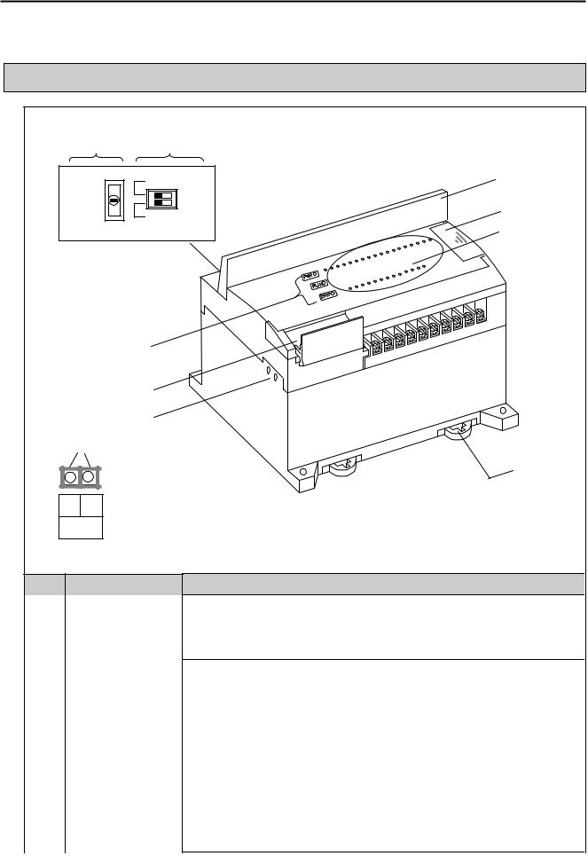
Chapter 4 Names of Parts
Chapter 4. Names of Parts
4.1 Main Unit
|
|
|
|
|
|
|
BUILT_IN CNET |
|
|
|
RUN |
ON |
OFF |
|
PAU/REM |
|
|||
|
|
|
||
|
STOP |
ROM MODE |
||
|
|
|
||
|
|
|
|
|
|
|
|
|
|
|
|
|
|
|
|
|
|
|
|
|
|
|
|
|
|
|
|
|
|
- |
+ |
|
|
|
RS-485 |
|
|
|
|
No. |
|
Name |
|
|
|
|
|
Indicates status of power supply to the system |
|
|
PWR LED |
yOn : When the supplied power is normal |
|
|
|
yOff : When the supplied power is abnormal |
|
|
|
Indicates operating status of main unit |
|
CPU |
|
yOn : Indicates local key switch or remote running mode |
|
|
|
|
|
Condition |
RUN LED |
yOff : with the followings, LED turns off |
|
LED |
|
- When the supplied power to the main unit is abnormal. |
|
|
|
|
|
|
|
- While key switch is on stop mode |
|
|
|
- Detecting an error which makes operation stop |
|
|
|
Indicates operating status of CPU |
|
|
ERR LED |
yFlickering : self-inspected error |
|
|
|
yOff: CPU is working normal. |
4 -1
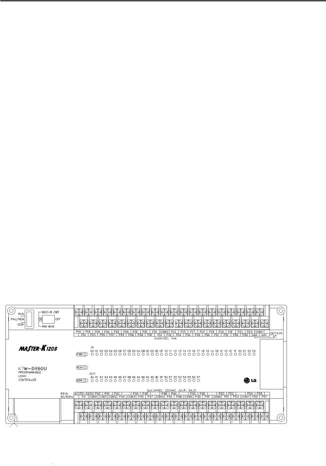
Chapter 4 Names of Parts
|
No |
|
Name |
|
Description |
|
|
|
|
|
|
|
|
|
|
|
I/O LED |
Indicates operating status of I/O |
|
|
|
|
|
|
|
|
|
|
|
|
Built-in RS-485 connector |
|
2-pin connector for built-in RS-485 communications. |
|
|
|
|
(Except K7M-DR10/14UE) |
|
|
|
|
|
|
|
|
Designates main unit’s operation mode |
|
|
|
|
|
|
yRUN : Run program operation |
|
|
|
|
Key switch for mode creation |
|
ySTOP: Stop program operation |
|
|
|
.(Except economic type) |
|
yPAU / REM: usage of each modules are as follows: |
|
|
|
|
|
|
|
|
|
|
|
|
|
|
- PAUSE : temporary stopping program operation |
|
|
|
|
|
|
- REMOTE : designates remote driving |
|
|
|
|
Dip-switch for Cnet I/F |
|
See Chapter 5. |
|
|
|
|
|
|
|
|
|
|
|
RS-232C connector |
|
9-pin DIN connector to connect with external devices like KGLWIN |
|
|
|
|
|
|
|
|
|
|
|
Expansion connector cover |
|
Connector cover to connect with expansion unit |
|
|
|
|
|
|
|
|
|
|
|
Terminal block cover |
|
Protection cover for wiring of terminal block |
|
|
|
|
|
|
|
|
|
|
|
Private hook DIN rail |
|
Private part hook for DIN rail |
|
|
|
|
|
|
|
|
4.1.160-points main unit (Standard)
1)K7M-DR60U
4 -2

Chapter 4 Names of Parts
2) K7M-DRT60U
3) K7M-DT60U
4.1.240-points main unit (Standard)
1)K7M-DR40U
4 -3
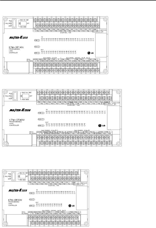
Chapter 4 Names of Parts
2) K7M-DRT40U
3) K7M-DT40U
4.1.330-points main unit (Standard)
1)K7M-DR30U
4 -4
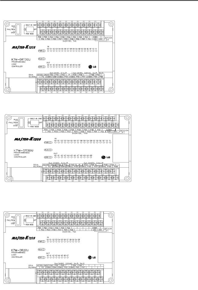
Chapter 4 Names of Parts
2) K7M-DRT30U
3) K7M-DT30U
4.1.420-points main unit (Standard)
1)K7M-DR20U
4 -5
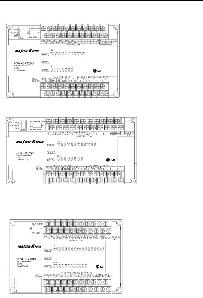
Chapter 4 Names of Parts
2) K7M-DRT20U
3) K7M-DT20U
4.1.530-points main unit (Economic)
1)K7M-DR30UE
4 -6
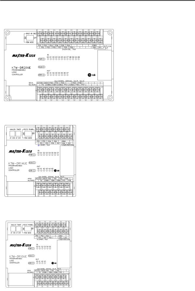
Chapter 4 Names of Parts
4.1.620-points main unit (Economic)
1)K7M-DR20UE
4.1.714-points main unit (Economic)
1)K7M-DR14UE
4.1.810-points main unit (Economic)
1)K7M-DR10UE
4 -7
 Loading...