


TH-M508
LVT1147-010A
[A,US,UN,UW,UG,UX]
English
DVD DIGITAL CINEMA SYSTEM
INSTRUCTIONS
Consists of XV-THM508, SP-PWM508,
SP-THM508F, SP-THM508C and
SP-THM505S
Consists of XV-THM303, SP-PWM303,
SP-THM303F, SP-THM303C and
SP-THM303S
G-1
Warnings, Cautions and Others
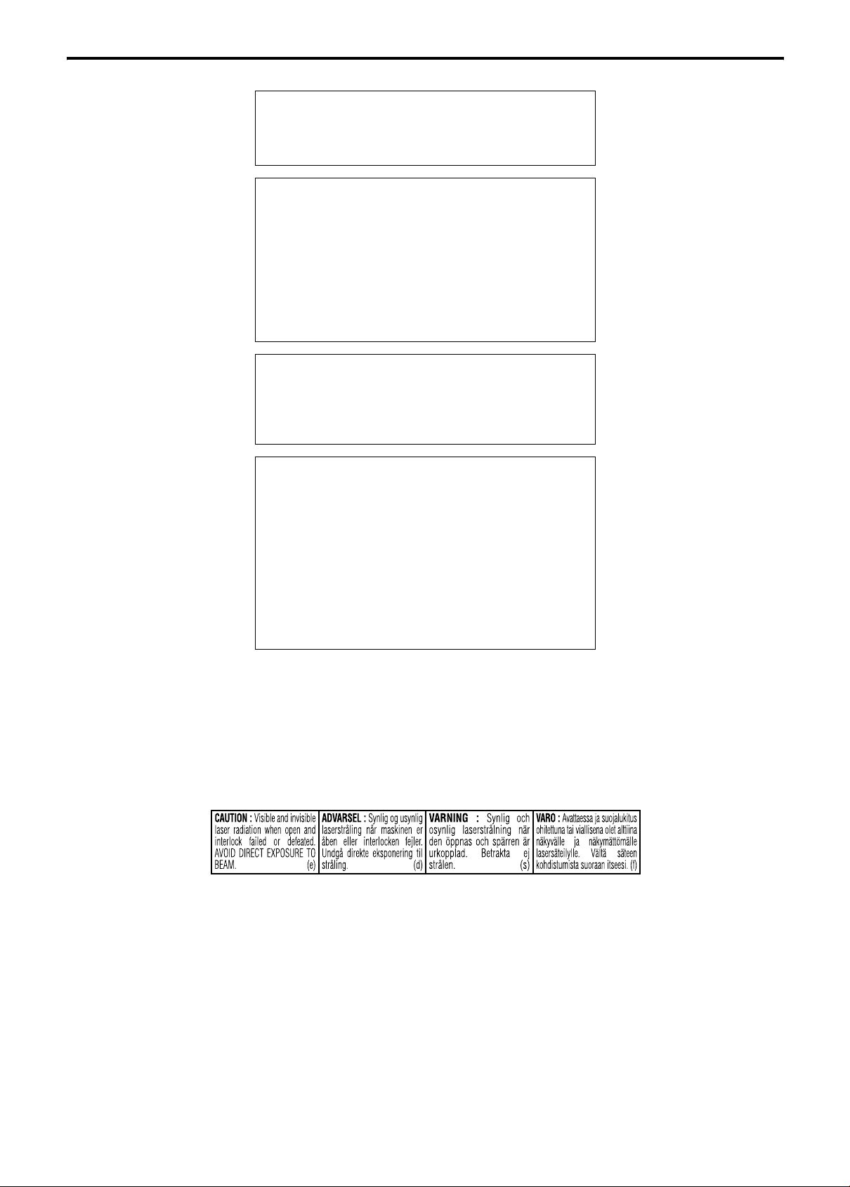
IMPORTANT FOR LASER PRODUCTS
1. CLASS 1 LASER PRODUCT
2.
CAUTION: Do not open the top cover. There are no user
serviceable parts inside the unit; leave all servicing to qualified
service personnel.
3.
CAUTION: Visible and invisible laser radiation when open and
interlock failed or defeated. Avoid direct exposure to beam.
4. REPRODUCTION OF LABEL: CAUTION LABEL, PLACED
INSIDE THE UNIT.
CAUTION
To reduce the risk of electrical shocks, fire, etc.:
1. Do not remove screws, covers or cabinet.
2. Do not expose this appliance to rain or moisture.
CAUTION — F button!
(XV-THM508/ XV-THM303)
Disconnect the mains plug to shut the power off completely
(the STANDBY lamp goes off).
The F button in any position does not disconnect the mains
line.
• When the system is on standby, the STANDBY lamp lights
red.
• When the system is turned on, the STANDBY lamp goes off.
The power can be remote controlled.
CAUTION
(SP-PWM508/ SP-PWM303)
The power supply to the subwoofer is linked to the center unit.
The POWER ON lamp on the subwoofer lights green when the
power is turned on.
CAUTION
• Do not block the ventilation openings or holes.
(If the ventilation openings or holes are blocked by a
newspaper or cloth, etc., the heat may not be able to get out.)
• Do not place any naked flame sources, such as lighted
candles, on the apparatus.
• When discarding batteries, environmental problems must be
considered and local rules or laws governing the disposal of
these batteries must be followed strictly.
• Do not expose this apparatus to rain, moisture, dripping or
splashing and that no objects filled with liquids, such as
vases, shall be placed on the apparatus.

Warnings, Cautions and Others
G-2
Caution: Proper Ventilation
To avoid risk of electric shock and fire and to protect from damage, place the apparatus on a level surface. The minimal clearances are
shown below:
8 cm
Wall or
obstructions
XV-THM508/
XV-THM303
3 cm 3 cm
15 cm
10 cm
Front
No
obstructions
Wall or obstructions
XV-THM508/
XV-THM303
SP-PWM508/
SP-PWM303
20 cm
15 cm 15 cm
Wall or
obstructions
SP-PWM508/
SP-PWM303
15 cm
Front
No
obstructions
Wall or obstructions

1
Table of contents
Introduction .....................................2
Notes on handling .................................................................2
Supplied accessories ............................................................2
About discs .....................................3
Playable disc types ...............................................................3
Description of parts and controls ... 5
Connections ....................................8
Connecting the FM and AM antennas ....................................8
Connecting the satellite (front, center, surround) speakers .......
9
Speaker layout ....................................................................11
Connecting a TV ..................................................................11
Connecting the powered subwoofer ....................................12
Connecting to an analog component ...................................12
Connecting to a digital component .....................................12
Setting the VOLTAGE SELECTOR switch .......................................
13
Connecting the power cord .................................................13
Operating external components with
the remote control ........................14
Operating the TV .................................................................14
Operating the DBS tuner or CATV converter .......................14
Operating the VCR ..............................................................15
Basic operations ...........................16
Turning the system on/off ...................................................16
Selecting the source to play ................................................17
Adjusting the volume [VOLUME] ........................................17
Listening with headphones (not supplied) ..........................17
Turning off the sound temporarily [MUTING] .....................17
Adjusting the brightness of the indications [DIMMER] .......17
Sleep Timer [SLEEP] ...........................................................18
Adjusting the output level of the subwoofer and center/
surround speakers [SUBWFR, CENTER, SURR L/R] ...........18
Adjusting the treble sound [TREBLE] ..................................18
Changing the scan mode ....................................................18
Optimizing the speaker settings [Smart Surround Setup] ...19
Playback ........................................20
Basic playback ....................................................................20
One Touch Replay ...............................................................22
Fast-forward/fast-reverse search ........................................22
Skip to the beginning of a desired selection ........................22
Locating a desired title/group using number buttons ..........23
Playing back a bonus group ................................................23
Advanced operations .................... 24
Using the surround mode ...................................................24
Using the on-screen bar .....................................................25
Playing from a specified position on a disc .........................27
Using the file control display ..............................................28
Resume Playback ...............................................................29
Selecting a view angle .........................................................29
Selecting the subtitle ..........................................................29
Selecting the audio .............................................................30
Special picture playback .....................................................30
Program Playback ...............................................................32
Random Playback ...............................................................33
Repeat Playback .................................................................33
Tray lock .............................................................................34
Sound and other settings ....................................................35
Setting DVD preferences .............. 36
Using the setup menus .......................................................36
Menu description ................................................................36
Tuner operations ........................... 40
Setting the AM tuner interval spacing .................................40
Manual tuning .....................................................................40
Preset tuning ......................................................................41
Selecting the FM reception mode ........................................41
Reducing the noise of AM broadcast ..................................41
AV COMPU LINK remote control
system ........................................... 42
KARAOKE operations .................... 43
Basic KARAOKE operation ..................................................43
Reserving songs .................................................................44
Selecting audio ...................................................................44
Adding an echo effect to your voice ....................................45
Shifting the pitch of the playback sound .............................45
References .................................... 46
Maintenance .......................................................................46
Troubleshooting ..................................................................46
Specifications .....................................................................47

2
Introduction
7 Important cautions
Installation of the system
• Select a place which is level, dry and neither too hot nor too cold;
between 5°C and 35°C.
• Leave sufficient distance between the system and the TV.
• Do not use the system in a place subject to vibration.
Power cord
• Do not handle the power cord with wet hands!
• A small amount of power is always consumed while the power
cord is connected to the wall outlet (center unit only).
• When unplugging the power cord from the wall outlet, always
pull on the plug, not the power cord.
To prevent malfunctions of the system
• There are no user-serviceable parts inside. If anything goes
wrong, unplug the power cord and consult your dealer.
• Do not insert any metallic object into the system.
• Do not use any non-standard shape disc (like a heart, flower or
credit card, etc.) available on the market, because it may damage
the system.
• Do not use a disc with tape, stickers, or paste on it, because it
may damage the system.
Note about copyright laws
Check the copyright laws in your country before recording from the
discs. Recording of copyrighted material may infringe copyright
laws.
Note about copyguard system
The discs are protected by copyguard system. When you connect
the system to your VCR directly, the copyguard system activates
and the picture may not be played back correctly.
7 Safety precautions
Avoid moisture, water and dust
Do not place the system in moist or dusty places.
Avoid high temperatures
Do not expose the system to direct sunlight and do not place it near
a heating device.
When you are away
When away on travel or for other reasons for an extended period of
time, disconnect the power cord plug from the wall outlet.
Do not block the vents
Blocking the vents may damage the system.
Care of the cabinet
When cleaning the system, use a soft cloth and follow the relevant
instructions on the use of chemically-coated cloths. Do not use
benzene, thinner or other organic solvents including disinfectants.
These may cause deformation or discoloring.
If water gets inside the system
Turn the system off and disconnect the power cord plug from the
wall outlet, then call the store where you made your purchase.
Using the system in this condition may cause fire or electrical
shock.
Check to be sure you have all of the supplied accessories.
The number in parentheses is the quantity of the pieces supplied.
If anything is missing, contact your dealer immediately.
• Remote control (1)
• Batteries (2)
• FM antenna (1)
• AM loop antenna (1)
• Power cord (1)
• System cord (1)
• Composite video cord (1)
• Speaker cords (TH-M508 only)
For satellite (front left/right) and center speakers (3)
For satellite speakers (surround left/right) (2)
• Screws (TH-M508 only)
M4 x 20 mm:
For front speakers (8)
• AC plug adaptor (2) (except for Australia)
Notes on handling
Paste
Sticker
Label sticker
Supplied accessories
3
About discs
This system has been designed to play back the following discs:
DVD VIDEO, DVD AUDIO, Video CD (VCD), Super Video CD
(SVCD), Audio CD (CD), CD-R and CD-RW.
• This system accommodates the NTSC and PAL system. When
you play an NTSC disc with the scan mode set to “PAL ”
(A pg. 18), the NTSC video signal is converted to the PAL60
signal and output.
• This system can also play MP3, WMA, JPEG and MPEG4 files
recorded on CD-Rs and CD-RWs. (A pg. 20)
• This system can also play finalized DVD-R/-RWs recorded in
DVD VIDEO format. However, some discs may not be played
because of their disc characteristics or recording conditions.
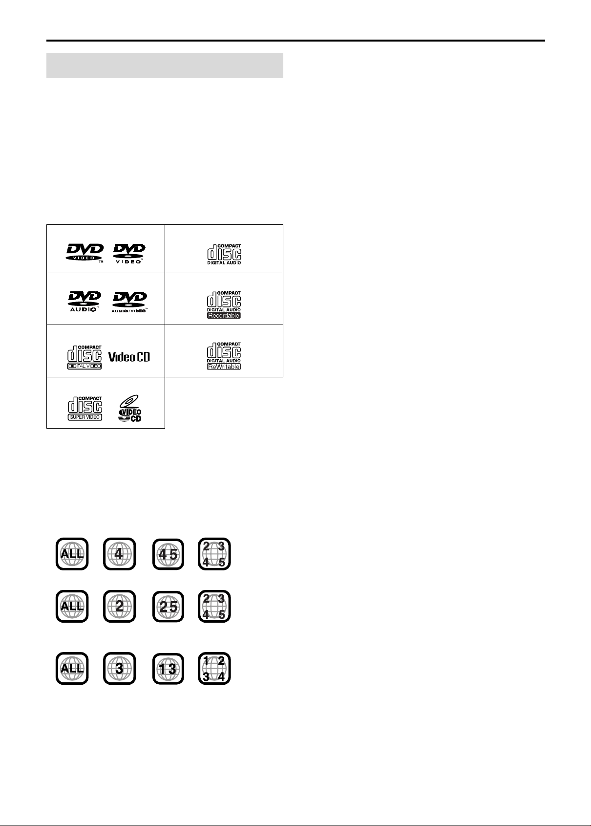
Discs you can play:
DVD Logo is a trademark of DVD Format/Logo Licensing
Corporation.
Region code of DVD VIDEO
DVD VIDEO players and DVD VIDEO discs have their own
Region Code numbers. This system can play back DVD VIDEO
discs whose Region Code numbers include the system’s Region
Code, which is indicated on the rear panel.
If a DVD with an improper Region Code number is loaded,
“REGION CODE ERROR!” appears on the TV screen and
playback cannot start.
• The following discs cannot be played back:
DVD-ROM, DVD-RAM, SACD, CD-ROM, CD-I (CD-I Ready),
Photo CD, etc.
Playing back these discs will generate noise and damage the
speakers.
• On some DVD VIDEOs, DVD AUDIOs, VCDs or SVCDs,
their actual operation may be different from what is
explained in this manual. This is due to the disc
programming and disc structure, not a malfunction of this
system.
Notes on CD-R and CD-RW
• User-edited CD-Rs (Recordable) and CD-RWs (Rewritable) can
be played back only if they are already “finalized”.
• This system can play CD-Rs or CD-RWs recorded on a personal
computer if they have been recorded in the audio CD format.
This system can also play CD-Rs or CD-RWs if MP3, WMA,
JPEG or MPEG4 files are recorded on them.
However, some discs may not be played back because of their
disc characteristics, recording conditions, or damage or stain on
them.
Especially, the configuration and characteristics of an MP3,
WMA, JPEG or MPEG4 disc are determined by the writing
(encoding) software and hardware used for recording. Therefore,
due to the software and hardware used, the following symptoms
may occur:
• Some discs may not be played back.
• Some tracks on an MP3 or WMA disc may be skipped or may
not be played back normally.
• Some files on a JPEG or MPEG4 disc may be played back
distortedly.
• Before playing back CD-Rs or CD-RWs, read their instructions
or cautions carefully.
• CD-RWs may require a longer readout time. This is caused by
the fact that the reflectance of CD-RWs is lower than that of
regular CDs.
Playable disc types
DVD VIDEO CD
DVD AUDIO CD-R
VCD CD-RW
SVCD
Example of playable DVD:
For Australia, Central and South America
For Middle East
Except for Australia, Central and South America, and Middle
East

About discs
4
Notes on MP3/WMA/JPEG/MPEG4 discs
• MP3/WMA/JPEG/MPEG4 discs (either CD-R or CD-RW)
require a longer readout time. (It differs due to the complexity of
the directory/file configuration.)
• When making an MP3/WMA/JPEG/MPEG4 disc, select ISO
9660 Level 1 or Level 2 for the disc format.
• This system supports “multi-session” discs (up to 20 sessions).
• This system cannot play “packet write” discs.
• The system can only play MP3/WMA/JPEG/MPEG4 files with
the following file extensions;
MP3: “.MP3”, “.Mp3”, “.mP3” and “.mp3”
WMA: “.wma”, “.WMA” and any uppercase and lowercase
combination (such as “.Wma”)
JPEG: “.jpg”, “.jpeg”, “.JPG”, “.JPEG” and any uppercase and
lowercase combination (such as “.Jpg”)
MPEG4: “.asf”, “.ASF” and any uppercase and lowercase
combination (such as “.Asf”)
• If different type of files (audio (MP3/WMA), still picture
(JPEG), and video (MPEG4) files) are recorded on a disc, set the
FILE TYPE setting in the PICTURE menu to the appropriate
setting for the data to be read. (A pg. 37)
• The system recognizes up to 150 tracks (files) per group, 99
groups per disc, and the total number of the tracks (files) that the
system can play is 1000. For example, if you set FILE TYPE to
AUDIO (A pg. 37) and play a disc that contains 500 MP3 tracks,
200 JPEG files, and 600 WMA tracks, the system can play 500
MP3 tracks and the first 500 of 600 WMA tracks.
• Some MP3/WMA/JPEG/MPEG4 discs may not be played back
normally because of their disc characteristics or recording
conditions.
Notes on MP3/WMA discs only
• The system supports MP3 files recorded with a bit rate of 32 –
320 kbps and a sampling frequency of 16 kHz, 22.05 kHz,
24 kHz*, 32 kHz, 44.1 kHz, or 48 kHz.
• If the tag information (album name, artist, and track title, etc.) is
recorded on a disc, it appears in the file control display on the TV
screen. (A pg. 28)
• We recommend to record each piece of material (song) at a
sample rate of 44.1 kHz and at a data transfer rate of
128 (96*) kbps.
• Some tracks may be skipped or may not be played back
normally.
* For WMA only
Notes on JPEG discs only
• We recommend to record a file at 640 x 480 resolution. (If a file
has been recorded at a resolution of more than 640 x 480, it will
take a longer time to be displayed.)
• This system can only play baseline JPEG files.
• Some files on a JPEG disc may be played back distortedly.
Notes on MPEG4 disc only
• The system supports the types of simple profile as MPEG4 files
(MPEG4 SP).
• The system supports MPEG4 files recorded with the maximum
bit rate of 384 kbps and an audio codec of G.726. (To play the
MPEG4 file, it is required that G.726 formatted audio data is
contained in that file.)
• The maximum size of the played picture is at a 352 x 288 pixel
resolution (CIF).
• Some files may be skipped or may not be played normally.
This product incorporates copyright protection technology
that is protected by method claims of certain U.S. patents
and other intellectual property rights owned by Macrovision
Corporation and other rights owners. Use of this copyright
protection technology must be authorized by Macrovision
Corporation, and is intended for home and other limited
viewing uses only unless otherwise authorized by
Macrovision Corporation. Reverse engineering or
disassembly is prohibited.
“CONSUMERS SHOULD NOTE THAT NOT ALL HIGH
DEFINITION TELEVISION SETS ARE FULLY COMPATIBLE
WITH THIS PRODUCT AND MAY CAUSE ARTIFACTS TO BE
DISPLAYED IN THE PICTURE. IN CASE OF 525 OR 625
PROGRESSIVE SCAN PICTURE PROBLEMS, IT IS
RECOMMENDED THAT THE USER SWITCH THE
CONNECTION TO THE ‘STANDARD DEFINITION’ OUTPUT.
IF THERE ARE QUESTIONS REGARDING OUR TV SET
COMPATIBILITY WITH THIS MODEL 525p AND 625p DVD
PLAYER, PLEASE CONTACT OUR CUSTOMER SERVICE
CENTER.”
USE OF THIS PRODUCT IN ANY MANNER THAT COMPLIES
WITH THE MPEG-4 VISUAL STANDARD IS PROHIBITED,
EXCEPT FOR USE BY A CONSUMER ENGAGING IN
PERSONAL AND NON-COMMERCIAL ACTIVITIES.
5
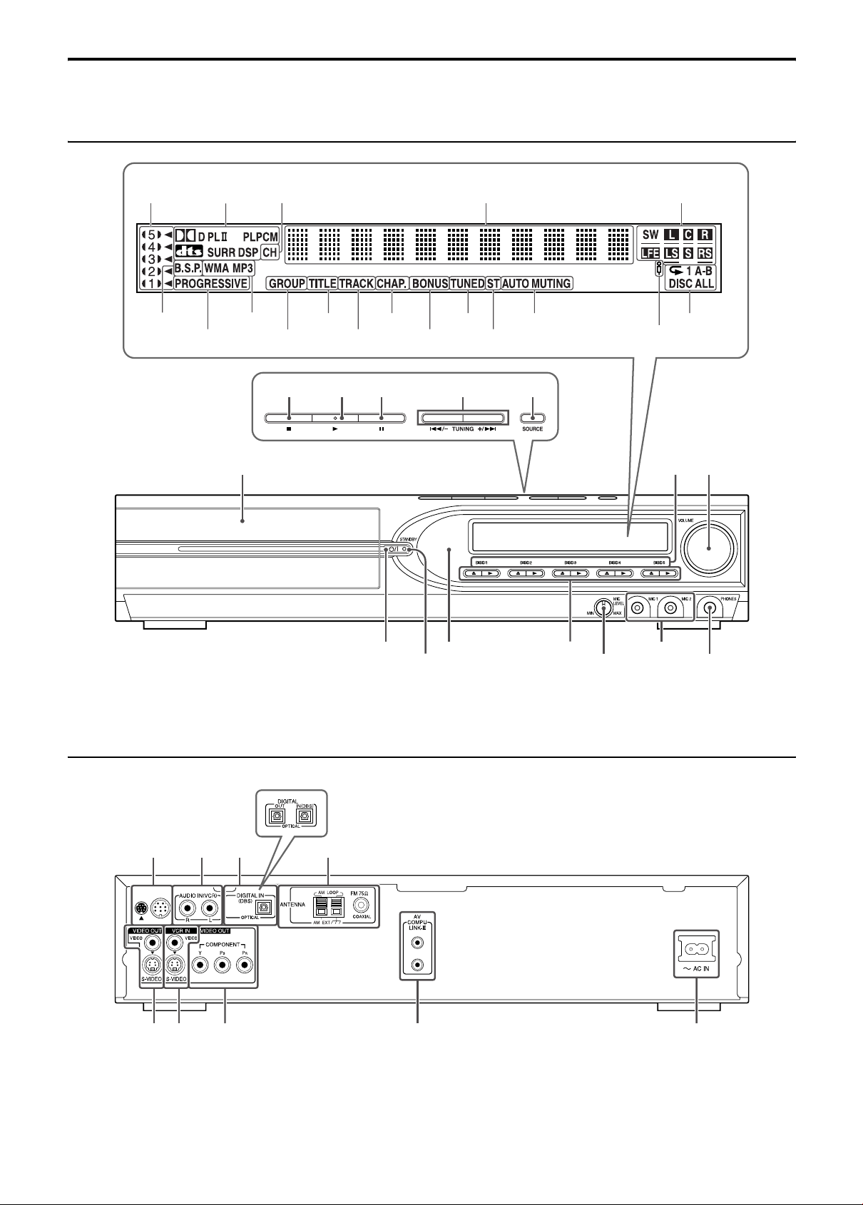
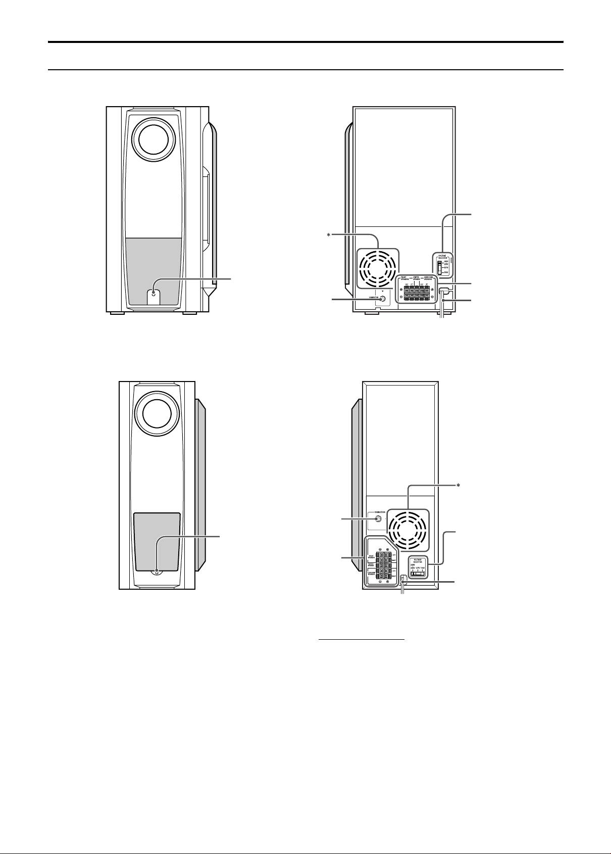
Description of parts and controls
The illustrations of the center unit and the subwoofer used in this manual are of TH-M508 unless otherwise noted.
Front panel (center unit)
Rear panel (center unit)
Display window
pg. 22 pg. 25 pg. 41 pg. 21 pg. 25
pg. 18
pg. 21
pg. 23
pg. 31 pg. 40
pg. 40
pg. 41 pg. 33
pg. 20 pg. 20 pg. 20 pg. 22, 40 pg. 17
Disc tray (inside): pg. 20
pg. 16
Remote sensor:
pg. 7
pg. 20
pg. 17
pg. 17
pg. 16
pg. 21 pg. 21
pg. 21 pg. 21
pg. 22
pg. 43
pg. 43
pg. 43
pg. 12 pg. 12 pg. 12
pg. 12
pg. 8
pg. 11 pg. 11 pg. 42 pg. 13
For TH-M508
Description of parts and controls
6
Powered subwoofer
SP-PWM508
SP-PWM303
* Do not block the ventilation openings.
NOTE
• For safety reasons, always ensure that there is sufficient space behind
the powered subwoofer.
Front
Rear
pg. 9
Power cord:
pg. 13
POWER ON
lamp:
pg. 16
pg. 12
pg. 13
Front
Rear
POWER ON
lamp:
pg. 16
pg. 10
Power co rd: pg. 13
pg. 12
pg. 13
(except for Australia)
Description of parts and controls
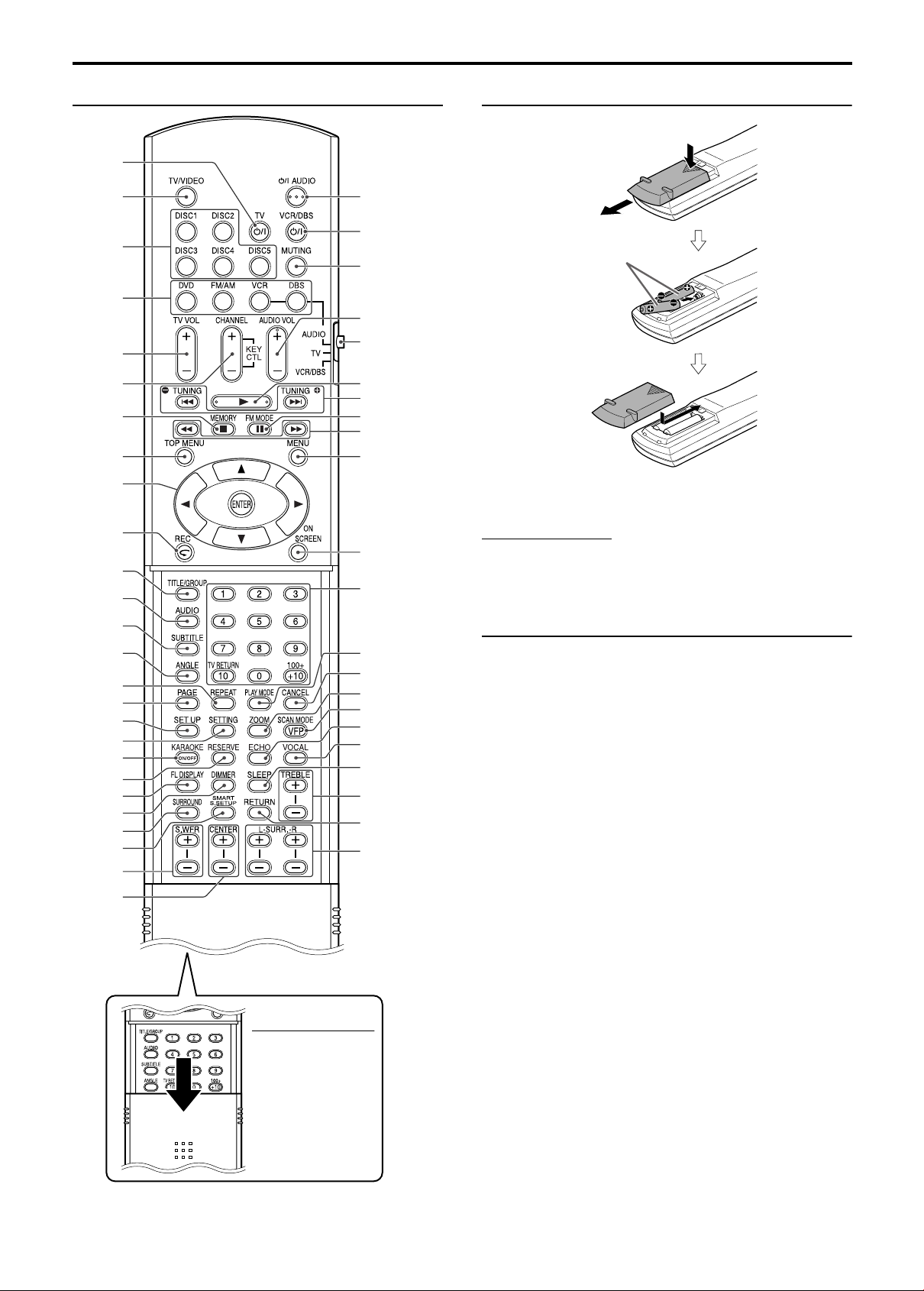
7
Remote control Putting batteries in the remote control
If the range or effectiveness of the remote control decreases,
replace both batteries.
CAUTION
• Do not expose batteries to heat or flame.
Operating the system from the remote
control
Aim the remote control directly to the front panel of the center unit.
• Do not hide the remote sensor.
NOTE
• To use the buttons
under the cover, slide
down the cover.
pg. 14
pg. 14
pg. 20
pg. 17
pg. 14
pg. 14,
45
pg. 20,
41
pg. 27
pg. 20
pg. 20, 41
pg. 18,
36
pg. 15,
22
pg. 23
pg. 30
pg. 29
pg. 29
pg. 31
pg. 36
pg. 33
pg. 35
pg. 17
pg. 21
pg. 25
pg. 19
pg. 18
pg. 16
pg. 14, 15
pg. 17
pg. 17
pg. 14 – 40
pg. 22, 40
pg. 22
pg. 27
pg. 25
Number
buttons:
pg. 23
pg. 32, 33
pg. 18, 31
pg. 31
pg. 18
pg. 18
pg. 27
pg. 18
pg. 18
pg. 32
pg. 44
pg. 43
pg. 45
pg. 44
R6P (SUM-3)/AA (15F)
type dry-cell batteries
(supplied)
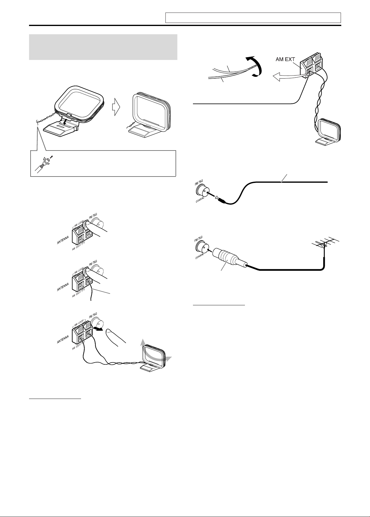
8
Connections
7 AM loop antenna
Setting up supplied AM loop antenna
Connecting AM loop antenna
• Turn the loop antenna until you have the best reception during
AM broadcast program reception.
NOTE
• Make sure the antenna conductors do not touch any other terminals,
connecting cords and power cords. This could cause poor reception.
If reception is poor
7 FM antenna
If reception is poor
NOTE
• We recommend that you use coaxial cable for the FM antenna as it is
well-shielded against interference.
Connecting the FM and
AM antennas
If the antenna cord is covered with the insulation
coat, twist and pull the insulation coat off and
remove.
1
Center unit
2
3
Antenna cord
Outdoor single vinyl-covered wire antenna
(not supplied)
AM loop antenna
Center unit
Extend the supplied FM antenna
horizontally.
Center unit
FM antenna (supplied)
Outdoor FM antenna
(not supplied)
Outdoor FM antenna cord
(not supplied)
Center unit
Standard type (75 C
coaxial) connector
Do not connect the power cord until all other connections have been made.
Connections
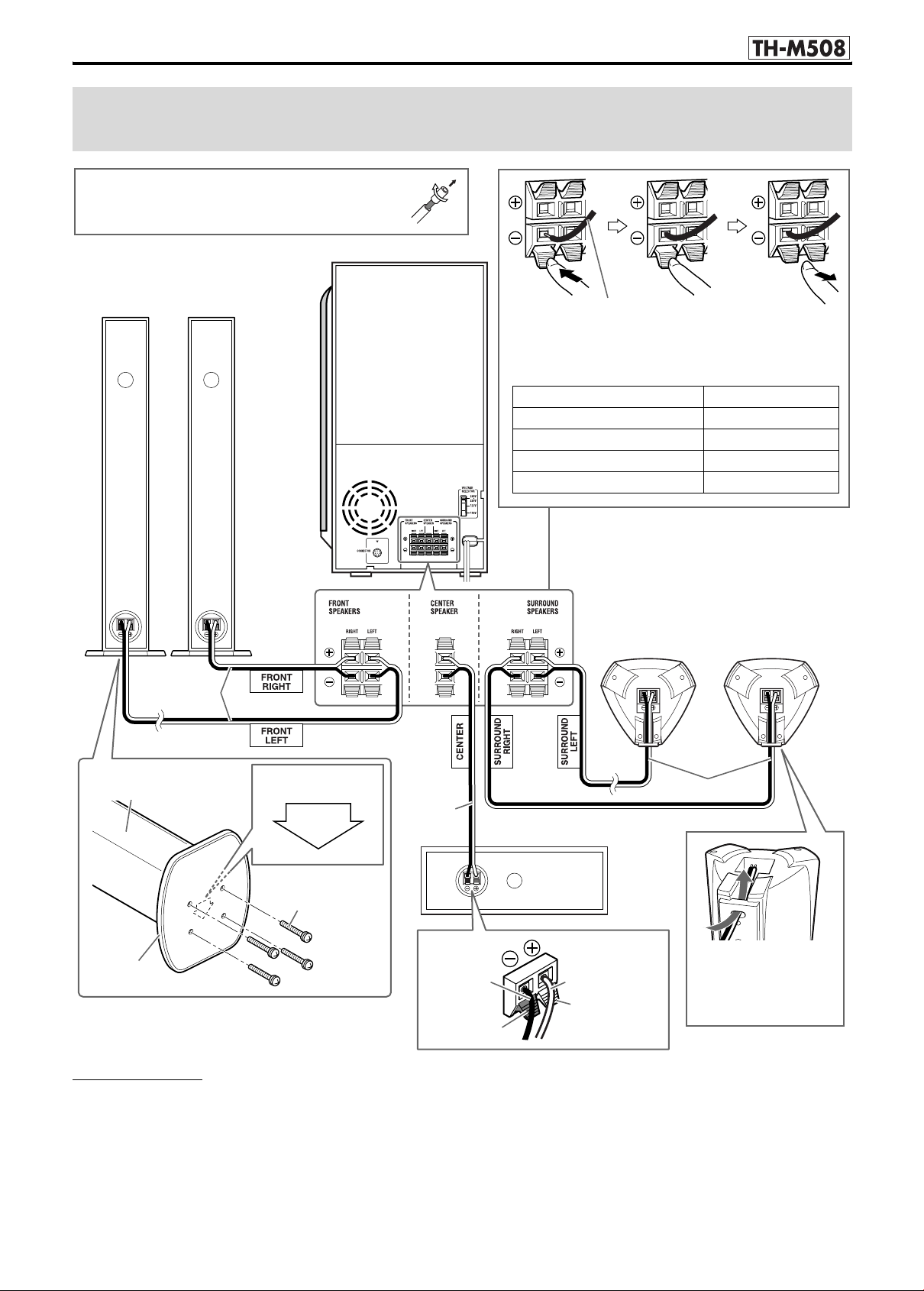
9
CAUTION
• When you connect speakers other than the supplied ones, use
speakers of the same speaker impedance (SPEAKER IMPEDANCE)
indicated near the speaker terminals on the rear of the powered
subwoofer.
• DO NOT connect more than one speaker to one speaker terminal.
• When installing the satellite speakers on the wall;
• Be sure to have them installed on the wall by a qualified personnel.
DO NOT install the satellite speakers on the wall by yourself to
avoid unexpected damage from their falling off the wall due to
incorrect installation or weakness in wall structure.
• Care must be taken in selecting a location for speaker installation
on a wall. Injury to personnel or damage to equipment may result
if the speakers installed interfere with daily activities.
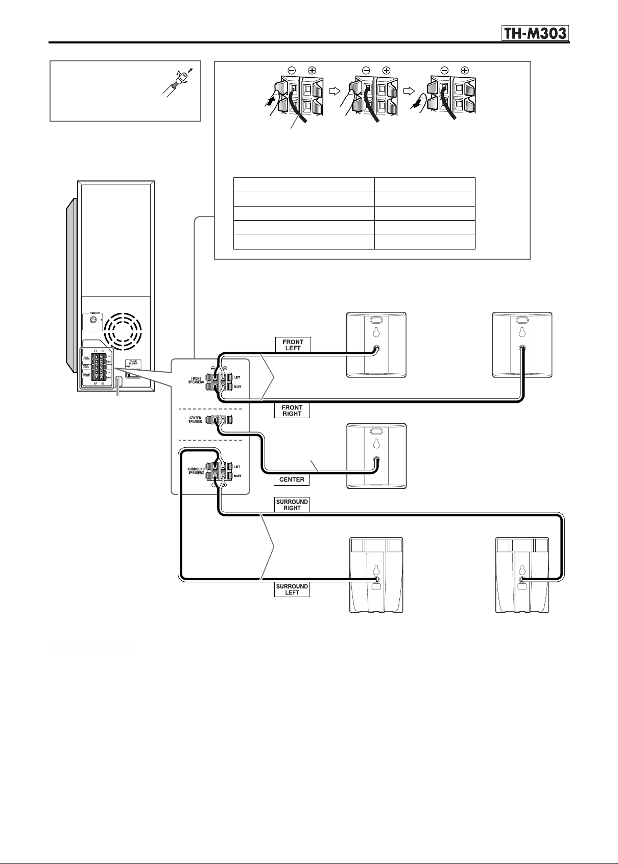
Connecting the satellite (front, center, surround)
speakers
FRONT
Surround speakers
SP-THM505S
(Bottom)
Center speaker
SP-THM508C
Front speakers
SP-THM508F
• Connect the silver cords to the black (r) terminals.
• Connect the copper cords to the (q) terminals referring to
the table below:
Speaker cord (supplied)
FRONT SPEAKERS (RIGHT) Red
FRONT SPEAKERS (LEFT) White
CENTER SPEAKER Green
SURROUND SPEAKERS (RIGHT) Gray
SURROUND SPEAKERS (LEFT) Blue
Before connecting the speaker cords;
Twist and pull the insulation coat off and remove.
Powered subwoofer
SP-PWM508
4m
10 m
Route the speaker cord
through the hole on the
bracket.
4m
Speaker (rear side)
Base plate
Screw M4 x 20 mm
(supplied)
Top of the base plate
Silver
Copper
Black
Red
This page is for
Connections
10
CAUTION
• When you connect speakers other than the supplied ones, use
speakers of the same speaker impedance (SPEAKER IMPEDANCE)
indicated near the speaker terminals on the rear of the powered
subwoofer.
• DO NOT connect more than one speaker to one speaker terminal.
• When installing the satellite speakers on the wall;
• Be sure to have them installed on the wall by a qualified personnel.
DO NOT install the satellite speakers on the wall by yourself to
avoid unexpected damage from their falling off the wall due to
incorrect installation or weakness in wall structure.
• Care must be taken in selecting a location for speaker installation
on a wall. Injury to personnel or damage to equipment may result
if the speakers installed interfere with daily activities.
Surround speakers
SP-THM303S
Center speaker
SP-THM303C
Front speakers
SP-THM303F
• Connect the silver cords to the black (r) terminals.
• Connect the copper cords to the (q) terminals referring to the table below:
Speaker cord (supplied)
FRONT SPEAKERS (LEFT) White
FRONT SPEAKERS (RIGHT) Red
CENTER SPEAKER Green
SURROUND SPEAKERS (LEFT) Blue
SURROUND SPEAKERS (RIGHT) Gray
Before connecting the
speaker cords;
Twist and pull the
insulation coat off and
remove.
Powered subwoofer
SP-PWM303
4m
10 m
4m
This page is for
Connections
11
NOTE
• Although the satellite speakers and the powered subwoofer are
magnetically shielded, the TV screen may appear mottled. In this
case, keep enough distance between the speakers and the TV.
• The speakers are magnetically shielded to avoid color distortions on
TVs. However, if not installed properly, they may cause color
distortions. So, pay attention to the following when installing the
speakers.
– When placing the speakers near a TV set, turn off the TV’s main
power switch or unplug it before installing the speakers. Then wait
at least 30 minutes before turning on the TV’s main power switch
again.
Some TVs may still be affected even though you have followed the
above. If this happens, move the speakers away from the TV.
• Place the satellite speakers on a flat and level surface.
• Be sure to place the powered subwoofer to the TV’s right. If you place
the powered subwoofer to the TV’s left, keep sufficient distance
between them to prevent the TV screen from appearing mottled.
For TH-M508 only:
• Do not lean against the satellite speakers, as the speakers could fall
down or break, possibly causing injury. Especially be careful not to
let children lean against them.
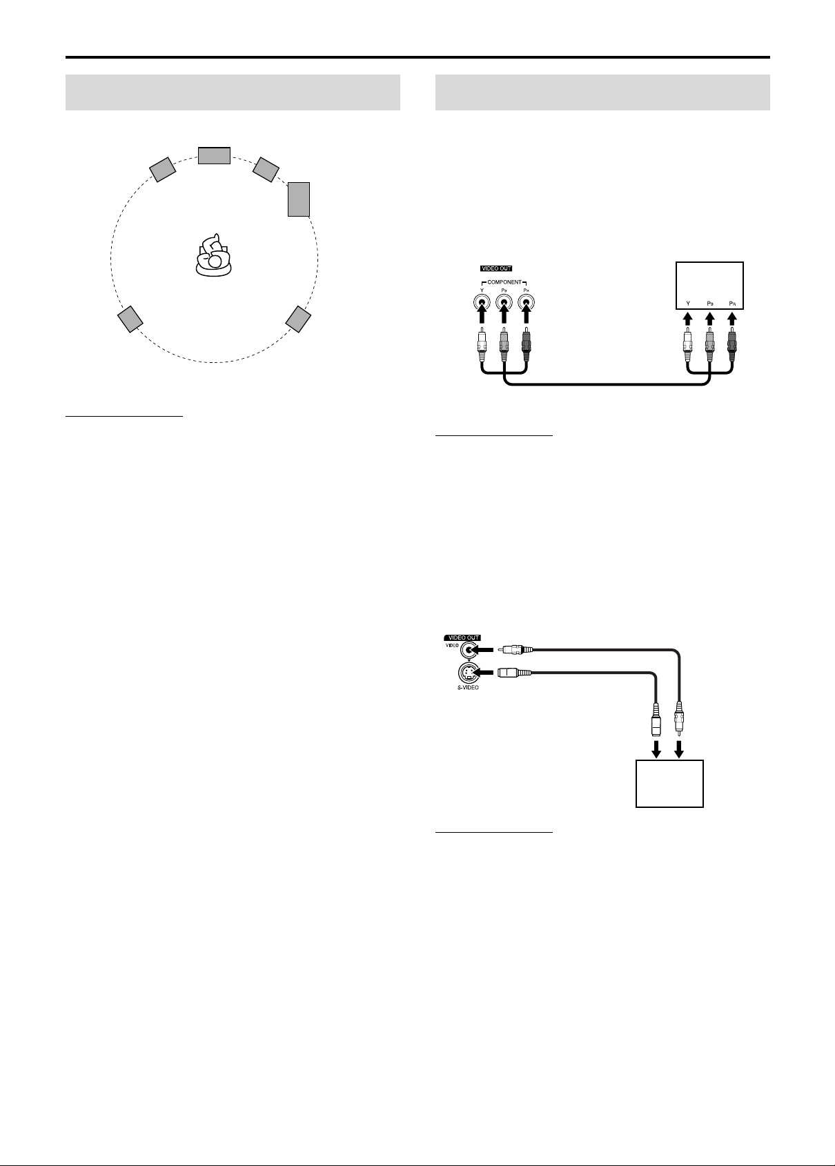
• You can get better picture quality in the order — Component
video > S-video > Composite video.
• Distortion of picture may occur when connecting to the TV via a
VCR, or to a TV with a built-in VCR.
• You need to set “MONITOR TYPE” in the PICTURE menu
correctly according to the aspect ratio of your TV. (A pg. 37)
7 To connect a TV equipped with the component video
input jacks
NOTE
• If your TV supports progressive video input, you can enjoy a high
quality picture by setting the progressive scan mode to active.
(A pg. 18)
• If the component video input jacks of your TV are of the BNC type,
use a plug adapter (not supplied) to convert the pin plugs to BNC
plugs.
• The component video signals can be output only when you select
“DVD” as the source to play. (A pg. 17)
7 To connect a TV equipped with the composite video
or S-video jack
NOTE
• Select the appropriate scan mode according to your TV. See
“Changing the scan mode” (A pg. 18).
Speaker layout
Front right
speaker
Center speaker
Powered
subwoofer
Surround left
speaker
Surround right
speaker
Front left
speaker
Connecting a TV
Center unit
To component
video input
TV
Component video cord (not supplied)
Composite video cord
(supplied)
To composite
video input
S-video cord
(not supplied)
TV
To S-video input
Center unit
or
Align the 5 marks.
Connections
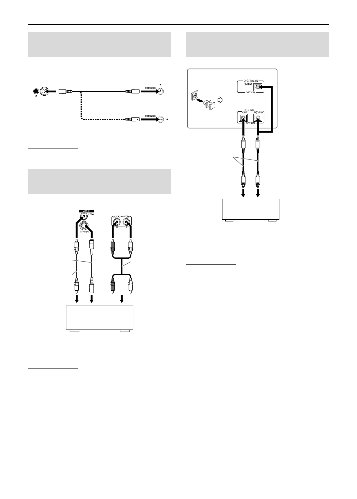
12
NOTE
• The way of connecting the system cord varies depending on the type
of the powered subwoofer.
You can enjoy the sound of an analog component.
NOTE
• The signals input to the VIDEO jack of the VCR IN jacks will be
output only from the VIDEO jack of the VIDEO OUT jacks, not from
the S-VIDEO jack of the VIDEO OUT jacks.
You can enjoy the sound of a digital component.
*1
For TH-M508 only:
This system can send digital audio signals to digital component
such as MD recorder or AV receiver. For details of output signal
selection, see “DIGITAL AUDIO OUTPUT” (A pg. 37).
*2
DBS = Direct Broadcasting Satellite
NOTE
• Only digital audio signals can be input when selecting “DBS” as the
source to play. (A pg. 17) When connecting a video component such
as a DBS tuner, operate this system to listen to the sound.
• When DBS is selected as the source, PCM signal is output from
DIGITAL OUT.
Connecting the powered
subwoofer
Connecting to an analog
component
Powered
subwoofer
System cord
(supplied)
Center unit
Align the 5 marks.
Align the 5 marks.
or
SP-PWM508
SP-PWM303
RCA pin plug
cord
(not supplied)
A To composite video output
B To S-video output
C To audio output
AB C
Center unit
VCR (A C or B C)
TV (C)
Cassette recorder (C)
Composite video
cord
(not supplied)
S-video cord
(not supplied)
or
Connecting to a digital
component
Digital optical cord
(not supplied)
To digital optical output
DBS
*
2
tuner
MD recorder
Center unit
To digital optical
input
*
1
TH-M303
TH-M508
Connections
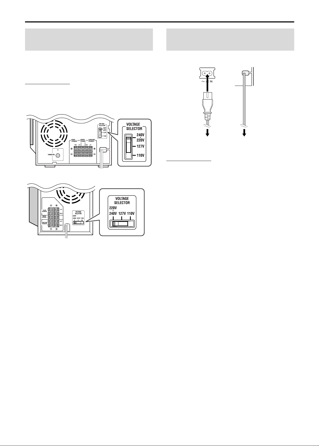
13
To avoid damaging the powered subwoofer, set the VOLTAGE
SELECTOR switch to the voltage of your area.
When you change the position of the VOLTAGE SELECTOR
switch, use a tool such as a slotted screwdriver, etc.
CAUTION
DO NOT plug the power cord of the powered subwoofer
before setting the VOLTAGE SELECTOR switch to the
correct voltage.
Make sure that all other connections have been completed.
CAUTION
• Disconnect the power cord before cleaning or moving the system.
• Do not pull on the power cord to unplug the cord. When unplugging
the cord, always grasp and pull the plug so as not to damage the cord.
• If the AC outlets do not match the AC plugs, use the supplied AC plug
adaptors.
Setting the VOLTAGE
SELECTOR switch
SP-PWM303 (except for Australia)
SP-PWM508
Connecting the power
cord
Center unit Powered
subwoofer
Power cord
(supplied)
Power cord
Plug into AC outlets.
 Loading...