


ZyXEL Communications ES-2008 User Manual

Dimension ES-2008
Ethernet Switch
User's Guide
Version 1.02
March 2003

Dimension ES-2008 Ethernet Switch
Copyright
Copyright ©2003 by ZyXEL Communications Corporation
The contents of this publication may not be reproduced in any part or as a whole,
transcribed, stored in a retrieval system, translated into any language, or transmitted in
any form or by any means, electronic, mechanical, magnetic, optical, chemical,
photocopying, manual, or otherwise, without the prior written permission of ZyXEL
Communications Corporation.
Published by ZyXEL Communications Corporation. All rights reserved.
Disclaimer
ZyXEL does not assume any liability arising out of the application or use of any products,
or software described herein. Neither does it convey any license under its patent rights nor
the patents' rights of others. ZyXEL further reserves the right to make changes in any
products described herein without notice. This publication is subject to change without
notice.
Trademarks
Trademarks mentioned in this publication are used for identification purposes only and
may be properties of their respective owners.
ii Copyright

Dimension ES-2008 Ethernet Switch
ZyXEL Limited Warranty
ZyXEL warrants to the original end user (purchaser) that this product is free from any
defects in materials or workmanship for a period of up to two (2) years from the date of
purchase. During the warranty period and upon proof of purchase, should the product
have indications of failure due to faulty workmanship and/or materials, ZyXEL will, at its
discretion, repair or replace the defective products or components without charge for
either parts or labor and to whatever extent it shall deem necessary to restore the product
or components to proper operating condition. Any replacement will consist of a new or remanufactured functionally equivalent product of equal value, and will be solely at the
discretion of ZyXEL. This warranty shall not apply if the product is modified, misused,
tampered with, damaged by an act of God, or subjected to abnormal working conditions.
NOTE
Repair or replacement, as provided under this warranty, is the exclusive remedy of the
purchaser. This warranty is in lieu of all other warranties, express or implied, including
any implied warranty of merchantability or fitness for a particular use or purpose. ZyXEL
shall in no event be held liable for indirect or consequential damages of any kind of
character to the purchaser.
To obtain the services of this warranty, contact ZyXEL's Service Center for your Return
Material Authorization (RMA) number. Products must be returned Postage Prepaid. It is
recommended that the unit be insured when shipped. Any returned products without proof
of purchase or those with an out-dated warranty will be repaired or replaced (at the
discretion of ZyXEL) and the customer will be billed for parts and labor. All repaired or
replaced products will be shipped by ZyXEL to the corresponding return address, Postage
Paid. This warranty gives you specific legal rights, and you may also have other rights
that vary from country to country.
Online Registration
Register online at www.zyxel.com
.for free future product updates and information.
ZyXEL Limited Warranty iii

Dimension ES-2008 Ethernet Switch
Information for Canadian Users
The Industry Canada label identifies certified equipment. This certification means that the
equipment meets certain telecommunications network protective operation and safety
requirements. The Industry Canada does not guarantee that the equipment will operate to
a user's satisfaction.
Before installing this equipment, users should ensure that it is permissible to be connected
to the facilities of the local telecommunications company. The equipment must also be
installed using an acceptable method of connection. In some cases, the company's inside
wiring associated with a single line individual service may be extended by means of a
certified connector assembly. The customer should be aware that compliance with the
above conditions may not prevent degradation of service in some situations.
Repairs to certified equipment should be made by an authorized Canadian maintenance
facility designated by the supplier. Any repairs or alterations made by the user to this
equipment, or equipment malfunctions, may give the telecommunications company cause
to request the user to disconnect the equipment.
For their own protection, users should ensure that the electrical ground connections of the
power utility, telephone lines, and internal metallic water pipe system, if present, are
connected together. This precaution may be particularly important in rural areas.
Caution
Users should not attempt to make such connections themselves, but should contact the
appropriate electrical inspection authority, or electrician, as appropriate.
Note
This digital apparatus does not exceed the Class A limits for radio noise emissions from
digital apparatus set out in the radio interference regulations of Industry.
iv Information For Canadian Users

Dimension ES-2008 Ethernet Switch
Interference Statements and
Warnings
FCC Interference Statement
This device complies with Part 15 of the FCC rules. Operation is subject to the following
two conditions:
(1) This device may not cause harmful interference.
(2) This device must accept any interference received, including interference that may
cause undesired operations.
FCC Warning
This equipment has been tested and found to comply with the limits for a Class A digital
device, pursuant to Part 15 of the FCC Rules. These limits are designed to provide
reasonable protection against harmful interference in a commercial environment. This
equipment generates, uses, and can radiate radio frequency energy and, if not installed and
used in accordance with the instruction manual, may cause harmful interference to radio
communications. Operation of this equipment in a residential area is likely to cause
harmful interference in which case the user will be required to correct the interference at
his own expense.
CE Mark Warning:
This is a class A product. In a domestic environment this product may cause radio
interference in which case the user may be required to take adequate measures.
Taiwanese BCIQ A Warning:
Certifications
Refer to the product page at www.zyxel.com
Interference Statements and Warnings v
.

Dimension ES-2008 Ethernet Switch
Customer Support
When contacting your Customer Support Representative, please have the following
information ready:
Product model and serial number.
Firmware version information.
Warranty Information.
Date you received your product.
Brief description of the problem and the steps you took to solve it.
METHOD
LOCATION
WORLDWIDE
AMERICA
E-MAIL
SUPPORT/SALES
support@zyxel.com.tw +886-3-578-3942 www.zyxel.com
sales@zyxel.com.tw
support@zyxel.com +1-714-632-0882
sales@zyxel.com
support@zyxel.dk +45-3955-0700 www.zyxel.dk SCANDINAVIA
sales@zyxel.dk
support@zyxel.de +49-2405-6909-0 www.zyxel.de GERMANY
sales@zyxel.de
+45-3955-0707 ftp.zyxel.dk
+49-2405-6909-99
TELEPHONE/FAX WEB SITE/ FTP SITE REGULAR MAIL
www.europe.zyxel.com
+886-3-578-2439 ftp.europe.zyxel.com
www.zyxel.com NORTH
800-255-4101
+1-714-632-0858 ftp.zyxel.com
ZyXEL
Communications
Corp., 6 Innovation
Road II, ScienceBased Industrial Park,
Hsinchu 300, Taiwan
ZyXEL
Communications Inc.,
1650 Miraloma
Avenue, Placentia, CA
92870, U.S.A.
ZyXEL
Communications A/S,
Columbusvej 5, 2860
Soeborg, Denmark
ZyXEL Deutschland
GmbH. Adenauerstr.
20/A2 D-52146
Wuerselen, Germany
vi Customer Support


Dimension ES-2008 Ethernet Switch
Table of Contents
Copyright........................................................................................................................... ii
ZyXEL Limited Warranty.............................................................................................. iii
Information for Canadian Users .................................................................................... iv
Interference Statements and Warnings ...........................................................................v
Customer Support ........................................................................................................... vi
List of Figures .................................................................................................................. xi
List of Tables..................................................................................................................xiv
Preface ............................................................................................................................ xvi
Chapter 1 Getting to Know Your ES-2008.................................................................. 1-1
1.1 Features............................................................................................................ 1-1
1.2 Management Features...................................................................................... 1-1
1.3 Management Methods ..................................................................................... 1-2
1.4 Applications..................................................................................................... 1-2
Chapter 2 Hardware Description and Installation..................................................... 2-1
2.1 Hardware Installation....................................................................................... 2-1
2.2 Hardware Connections..................................................................................... 2-1
2.3 Front Panel LEDs ............................................................................................ 2-3
2.4 Rear Panel........................................................................................................ 2-5
2.5 Turning On the Switch..................................................................................... 2-6
Chapter 3 Introducing the Web Configurator............................................................ 3-1
3.1 Accessing the Web Configurator..................................................................... 3-1
3.2 Commonly Used Buttons................................................................................. 3-3
3.3 General Switch Information............................................................................. 3-4
3.4 Switch Console Port Settings........................................................................... 3-4
Chapter 4 Basic Switch Configuration ........................................................................ 4-1
4.1 Setting the IP Address of the Switch ............................................................... 4-1
4.2 Changing System Username and Password..................................................... 4-1
4.3 Resetting the Switch ........................................................................................ 4-2
4.4 Rebooting the Switch....................................................................................... 4-3
Chapter 5 Advanced Switch Configuration ................................................................ 5-1
5.1 Switch Configuration....................................................................................... 5-1
Chapter 6 Port Control ................................................................................................. 6-1
6.1 Configuring the Ethernet Ports ........................................................................ 6-1
6.2 View Port Status .............................................................................................. 6-2
6.3 Port Statistics ................................................................................................... 6-2
Chapter 7 Port Trunking.............................................................................................. 7-1
7.1 Introduction ..................................................................................................... 7-1
7.2 Configuring Port Trunking .............................................................................. 7-2
7.3 Viewing Static Trunk Group Information........................................................ 7-3
7.4 State Activity ................................................................................................... 7-4
viii Table of Contents

Dimension ES-2008 Ethernet Switch
Chapter 8 Filter and Security Setup ............................................................................8-5
8.1 IGMP ............................................................................................................... 8-5
8.2 Static MAC Address ......................................................................................8-10
8.3 Port Security................................................................................................... 8-11
8.4 MAC Address Filtering.................................................................................. 8-12
Chapter 9 VLAN............................................................................................................ 9-1
9.1 Introduction...................................................................................................... 9-1
9.2 VLAN Types.................................................................................................... 9-1
9.3 Selecting VLANSupport.................................................................................. 9-2
9.4 Port-Based VLAN Configuration ....................................................................9-3
9.5 Tag-Based VLAN Configuration..................................................................... 9-4
Chapter 10 Spanning Tree Protocol........................................................................... 10-1
10.1 Introduction.................................................................................................... 10-1
10.2 Activating Spanning Tree Protocol................................................................ 10-2
10.3 Configuring Spanning Tree Parameters ......................................................... 10-2
10.4 Viewing Root Bridge Information ................................................................. 10-3
10.5 Configuring Spanning Tree Port Parameters .................................................10-4
10.6 Viewing STP Port Status................................................................................10-5
Chapter 11 Port Mirroring ......................................................................................... 11-1
11.1 Introduction.................................................................................................... 11-1
11.2 Configuring Port Mirroring............................................................................ 11-1
Chapter 12 SNMP........................................................................................................ 12-1
12.1 About SNMP.................................................................................................. 12-1
12.2 Configuring SNMP ........................................................................................ 12-2
Chapter 13 Introducing the SMT............................................................................... 13-1
13.1 Introduction.................................................................................................... 13-1
13.2 Accessing the SMT Using Telnet ..................................................................13-1
13.3 Accessing the SMT Using the Console Port .................................................. 13-1
13.4 Initial SMT Screen......................................................................................... 13-2
13.5 The SMT Overview .......................................................................................13-3
13.6 Navigating the SMT Interface........................................................................ 13-3
13.7 SMT Main Menu............................................................................................ 13-5
Chapter 14 Basic System Setup .................................................................................. 14-1
14.1 Introduction.................................................................................................... 14-1
14.2 Administration Configuration ........................................................................ 14-2
Chapter 15 Switch Configuration...............................................................................15-1
15.1 Port and Trunk Group Settings ......................................................................15-1
15.2 Port Mirroring ................................................................................................ 15-2
15.3 VLAN ............................................................................................................ 15-4
15.4 Priority Configuration .................................................................................... 15-8
15.5 MAC Address Configuration ......................................................................... 15-9
15.6 Miscellaneous Configuration ....................................................................... 15-13
Chapter 16 Protocol Related Configuration.............................................................. 16-1
Table of Contents ix

Dimension ES-2008 Ethernet Switch
16.1 Introduction ................................................................................................... 16-1
16.2 STP Configuration......................................................................................... 16-1
16.3 SNMP Configuration..................................................................................... 16-4
16.4 GVRP Configuration ..................................................................................... 16-6
16.5 LACP Configuration...................................................................................... 16-7
Chapter 17 Status and Counters ................................................................................ 17-1
17.1 Status and Counters ....................................................................................... 17-1
Chapter 18 Firmware and Configuration File Maintenance................................... 18-1
18.1 Filename Convention..................................................................................... 18-1
18.2 Firmware Upgrade......................................................................................... 18-1
18.3 Configuration File Maintenance .................................................................... 18-4
Chapter 19 Troubleshooting....................................................................................... 19-1
19.1 Using LEDs to Diagnose Problems ............................................................... 19-1
19.2 Console Port .................................................................................................. 19-2
19.3 Telnet............................................................................................................. 19-3
19.4 Web Configurator .......................................................................................... 19-3
19.5 Login Username and Password...................................................................... 19-4
19.6 Improper Network Cabling and Topology..................................................... 19-4
Appendix A Setting up Your Computer’s IP Address ..................................................A
Appendix B........................................................................................................................ L
IP Subnetting ....................................................................................................................L
Appendix C Product Specifications.................................................................................T
Index .................................................................................................................................W
x Table of Contents

Dimension ES-2008 Ethernet Switch
List of Figures
Figure 1-1 Standalone Workgroup Example.................................................................... 1-3
Figure 1-2 Bridging Application Example....................................................................... 1-4
Figure 1-3 VLAN Application Example .......................................................................... 1-5
Figure 2-1 ES-2008.......................................................................................................... 2-1
Figure 2-2 ES-2008 with Fiber Port................................................................................. 2-2
Figure 2-3 ES-2008 with Gigabit Port ............................................................................. 2-2
Figure 2-4 Ethernet Port LEDs ........................................................................................ 2-4
Figure 2-5 Rear Panel ...................................................................................................... 2-5
Figure 3-1 Login Window................................................................................................3-1
Figure 3-2 Welcome Screen ............................................................................................. 3-2
Figure 3-3 Menu ..............................................................................................................3-2
Figure 3-4 Expanded Menu .............................................................................................3-2
Figure 3-5 Web Configurator Front Panel Display .......................................................... 3-3
Figure 3-6 Port Status ...................................................................................................... 3-3
Figure 3-7 Web Configurator: View Switch Information................................................. 3-4
Figure 3-8 Web Configurator: Serial Port Information.................................................... 3-4
Figure 4-1 Network Configuration ..................................................................................4-1
Figure 4-2 User Authentication........................................................................................ 4-2
Figure 4-3 Factory Default...............................................................................................4-2
Figure 4-4 System Reboot ...............................................................................................4-3
Figure 5-1 Switching Configuration: Advanced ..............................................................5-1
Figure 6-1 Port Configuration.......................................................................................... 6-1
Figure 6-2 Port Statistics.................................................................................................. 6-3
Figure 7-1 Trunking: Aggregator Setting......................................................................... 7-2
Figure 7-2 Trunking: Aggregator Information. ................................................................ 7-3
Figure 7-3 Trunk State Activity .......................................................................................7-4
Figure 8-1 Configuring IGMP ......................................................................................... 8-6
Figure 8-2 IGMP Example 1............................................................................................ 8-7
Figure 8-3 IGMP Example 2............................................................................................ 8-8
Figure 8-4 IGMP Example 2............................................................................................ 8-9
Figure 8-5 IGMP Snooping..............................................................................................8-9
Figure 8-6 Static MAC Address ..................................................................................... 8-11
Figure 8-7 Port Security................................................................................................. 8-12
Figure 8-8 MAC Address Filtering................................................................................ 8-13
Figure 9-1 Switch Configuration: Enable Protocols ........................................................ 9-2
Figure 9-2 VLAN Setup: Port-based VLAN Information................................................ 9-3
Figure 9-3 VLAN Setup: Port-based Configuration ........................................................ 9-3
Figure 9-4 VLAN Setup – 802.1Q with/without GVRP VLAN Information ..................9-4
Figure 9-5 Tag-Based VLAN: 802.1 Q VLAN Basic Setup ............................................ 9-5
Figure 9-6 VLAN Setup: 802.1Q VLAN Port Tagging ................................................... 9-5
List of Figures xi

Dimension ES-2008 Ethernet Switch
Figure 9-7 Tag-Based VLAN: Port VLAN ID................................................................. 9-6
Figure 10-1 Activating STP........................................................................................... 10-2
Figure 10-2 Configure Spanning Tree Parameters......................................................... 10-2
Figure 10-3 View STP Root Bridge Information........................................................... 10-3
Figure 10-4 Configuring STP Port Parameters .............................................................. 10-4
Figure 10-5 STP Port Status .......................................................................................... 10-5
Figure 11-1 Port Mirroring............................................................................................ 11-1
Figure 12-1 SNMP Management Model........................................................................ 12-1
Figure 12-2 SNMP Management................................................................................... 12-3
Figure 13-1 Starting a Telnet Session ............................................................................ 13-1
Figure 13-2 HyperTerminal Communication Parameter Settings Example................... 13-2
Figure 13-3 SMT: Login Screen.................................................................................... 13-2
Figure 13-4 SMT Overview........................................................................................... 13-3
Figure 13-5 SMT: Menu Breakdown............................................................................. 13-4
Figure 13-6 SMT: Main Menu....................................................................................... 13-5
Figure 14-1 SMT: Switch Configuration ....................................................................... 14-1
Figure 14-2 SMT: Device Configuration....................................................................... 14-2
Figure 14-3 SMT: Device Information.......................................................................... 14-3
Figure 14-4 SMT: IP Configuration............................................................................... 14-4
Figure 14-5 SMT: Username Configuration.................................................................. 14-5
Figure 14-6 SMT: Password Configuration................................................................... 14-5
Figure 15-1 SMT: Port/Trunk Configuration................................................................. 15-1
Figure 15-2 SMT: Port Monitoring Configuration ........................................................ 15-3
Figure 15-3 SMT: VLAN Configuration....................................................................... 15-4
Figure 15-4 SMT: VLAN Support Configuration: Setting VLAN Mode...................... 15-5
Figure 15-5 SMT: VLAN Support Configuration: 802.1Q............................................ 15-5
Figure 15-6 SMT: Add a VLAN Group......................................................................... 15-6
Figure 15-7 SMT: Edit/Delete a VLAN Group ............................................................. 15-8
Figure 15-8 SMT: Priority Configuration...................................................................... 15-9
Figure 15-9 SMT: MAC Address Configuration ......................................................... 15-10
Figure 15-10 SMT: Static MAC Address..................................................................... 15-10
Figure 15-11 SMT: Add Static MAC Address ............................................................. 15-11
Figure 15-12 SMT: MAC Address Filtering................................................................ 15-12
Figure 15-13 SMT: Edit MAC Address Filtering ........................................................ 15-12
Figure 15-14 SMT: Misc Configuration...................................................................... 15-13
Figure 15-15 SMT: Port Security ................................................................................ 15-14
Figure 15-16 SMT: Aging Time Setting ...................................................................... 15-15
Figure 15-17 SMT: Broadcast Storm Filter Mode....................................................... 15-15
Figure 15-18 SMT: Max Bridge Transmit Delay Bound ............................................. 15-16
Figure 16-1 SMT: Protocol Related Configuration ....................................................... 16-1
Figure 16-2 SMT: STP Configuration ........................................................................... 16-2
Figure 16-3 SMT: Enable STP ...................................................................................... 16-2
Figure 16-4 SMT: STP Parameters Setup...................................................................... 16-3
xii List of Figures

Dimension ES-2008 Ethernet Switch
Figure 16-5 SMT: STP Per Port Setting......................................................................... 16-3
Figure 16-6 SMT: SNMP Configuration........................................................................16-4
Figure 16-7 SMT: SNMP System Options..................................................................... 16-5
Figure 16-8SMT: SNMP Community Strings................................................................ 16-5
Figure 16-9 SMT: SNMP Trap Manager........................................................................16-6
Figure 16-10 SMT: Add SNMP Trap Manager.............................................................. 16-6
Figure 16-11 SMT: GVRP Configuration...................................................................... 16-7
Figure 16-12 SMT: LACP Configuration ...................................................................... 16-7
Figure 16-13 SMT: LACP Group Setting ......................................................................16-8
Figure 16-14 SMT: LACP State Activity....................................................................... 16-9
Figure 16-15 SMT: LACP Group Status...................................................................... 16-10
Figure 17-1 SMT: Status and Counters .......................................................................... 17-1
Figure 17-2 SMT: Port Status ........................................................................................17-2
Figure 17-3 SMT: Port Counters....................................................................................17-2
Figure 17-4 SMT: Switch Information........................................................................... 17-3
Figure 18-1 SMT: Startup Message ............................................................................... 18-2
Figure 18-2 1K Xmodem Firmware Upload Example................................................... 18-2
Figure 18-3 SMT: Firmware Upload Process ................................................................ 18-3
Figure 18-4 Web Configurator: Firmware Upgrade....................................................... 18-3
Figure 18-5 Web Configurator: Successful Firmware Retrieval.................................... 18-4
Figure 18-6 Backup Configuration ................................................................................ 18-4
Figure 18-7 Web Configurator: Backup Configuration File Successful ........................18-5
Figure 18-8 Web Configurator: Restore Configuration.................................................. 18-5
Figure 18-9 Web Configurator: Successful Configuration File Retrieval...................... 18-6
List of Figures xiii

Dimension ES-2008 Ethernet Switch
List of Tables
Table 2-1 Network Cable Types ...................................................................................... 2-3
Table 2-2 The Switch Power LED Description ............................................................... 2-3
Table 2-3 Ethernet Port LED Descriptions...................................................................... 2-4
Table 2-4 100FX Module LED Descriptions................................................................... 2-4
Table 2-5 Gigabit Module LED Descriptions.................................................................. 2-5
Table 3-1 Commonly Used Button .................................................................................. 3-3
Table 3-2 View Switch Information................................................................................. 3-4
Table 4-1 Network Configuration.................................................................................... 4-1
Table 4-2 User Authentication ......................................................................................... 4-2
Table 5-1 Switching Configuration: Advanced................................................................ 5-2
Table 6-1 Port Configuration ........................................................................................... 6-1
Table 6-2 Port Statistics................................................................................................... 6-3
Table 7-1 Trunking: Aggregator Setting .......................................................................... 7-2
Table 7-2 Aggregator Information ................................................................................... 7-3
Table 7-3 Trunk State Activity ......................................................................................... 7-4
Table 8-1 IGMP Message Descriptions ........................................................................... 8-5
Table 8-2 IGMP Query Mode.......................................................................................... 8-6
Table 8-3 IGMP Snooping............................................................................................. 8-10
Table 9-1 VLAN Operation Mode................................................................................... 9-2
Table 9-2 VLAN Setup: Port-based Configuration.......................................................... 9-4
Table 9-3 VLAN Setup: 802.1Q VLAN Port Tagging..................................................... 9-6
Table 9-4 Tag-Based VLAN: Port VLAN ID .................................................................. 9-6
Table 10-1 Recommended Path Cost............................................................................. 10-1
Table 10-2 Configure STP Parameter ............................................................................ 10-2
Table 10-3 View STP Root Bridge Information............................................................. 10-3
Table 10-4 STP Port Status............................................................................................ 10-5
Table 11-1 Port Mirroring.............................................................................................. 11-2
Table 12-1 SNMP Management..................................................................................... 12-3
Table 13-1 Control Key Descriptions ............................................................................ 13-4
Table 13-2 SMT Menu Summary.................................................................................. 13-5
Table 14-1 Switch Configuration Menu Choice ............................................................ 14-1
Table 14-2 SMT: Device Information............................................................................ 14-3
Table 14-3 SMT: IP Configuration ................................................................................ 14-4
Table 15-1 SMT: Port/Trunk Configuration .................................................................. 15-1
Table 15-2 SMT: Port Monitoring Configuration.......................................................... 15-3
Table 15-3 SMT: VLAN Support Configuration: 802.1Q ............................................. 15-5
Table 15-4 SMT: Add a VLAN Group .......................................................................... 15-7
Table 15-5 SMT: Priority Configuration........................................................................ 15-9
Table 15-6 Edit MAC Address Filtering SMT Field Descriptions............................... 15-12
Table 15-7 SMT: Port Security .................................................................................... 15-14
xiv List of Tables

Dimension ES-2008 Ethernet Switch
Table 15-8 SMT: Max Bridge Transmit Delay Bound................................................. 15-16
Table 16-1 SMT: STP Per Port Setting .......................................................................... 16-4
Table 16-2 SMT: LACP Group Setting.......................................................................... 16-8
Table 16-3 SMT: LACP State Activity...........................................................................16-9
Table 16-4 SMT: LACP Group Status .........................................................................16-10
Table 19-1 Troubleshooting Power LED .......................................................................19-1
Table 19-2 Troubleshooting LK/ACT LED ................................................................... 19-1
Table 19-3 Troubleshooting 100 LED............................................................................ 19-2
Table 19-4 Troubleshooting FD/COL LED....................................................................19-2
Table 19-5 Troubleshooting Console Port......................................................................19-2
Table 19-6 Troubleshooting Telnet ................................................................................ 19-3
Table 19-7 Troubleshooting Web Configurator.............................................................. 19-3
Table 19-8 Troubleshooting Internet Browser Display.................................................. 19-4
Table 19-9 Troubleshooting Login Username and Password......................................... 19-4
Table 19-10 Troubleshooting Improper Network Cabling and Topology ......................19-5
List of Tables xv

Dimension ES-2008 Ethernet Switch
Preface
Congratulations on your purchase of the ES-2008 Ethernet Switch.
About The ES-2008 Series Switches
The ES-2008 switch allows you to easily configure and manage your network via a web
browser. Just click your mouse instead of typing cryptic command strings. Moreover, the
ES-2008 can also be managed via SNMP.
There are four ES-2008 Ethernet switch models.
MODEL DESCRIPTION
ES-2008 Eight port 10/100M Ethernet switch.
ES-2008-SC Eight port 10/100M Ethernet switch with multi-mode fiber port.
ES-2008-SC30 Eight port 10/100M Ethernet switch with single-mode fiber port.
ES-2008-GTP Eight port 10/100M Ethernet switch with one gigabit port.
About this User’s Guide
This manual is designed to guide you through the configuration of your ES switch for its
various applications. All ES models are discussed together in this guide.
Unless specified, images of the ES-2008-SC are used throughout this document. Images
that directly relate to the other two models are used when referring to the key differences
between the models.
General Syntax Conventions
“Enter” means for you to type one or more characters and press the carriage
return. “Select” or “Choose” means for you to use one from the predefined
choices.
The SMT menu titles and labels are in Bold Times New Roman font. Predefined
field choices are in Bold Arial font. Command and arrow keys are enclosed in
square brackets. [ENTER] means the Enter, or carriage return key; [ESC] means
the Escape key and [SPACE BAR] means the Space Bar.
For brevity’s sake, we will use “e.g.” as shorthand for “for instance”, and “i.e.”
as shorthand for “that is” or “in other words” throughout this manual.
The Dimension ES-2008 Ethernet Switch models will be referred to as the ES-
2008 or simply as “the switch” in this manual.
Glossary
www.zyxel.com
contains an online glossary of networking terms.
xvi Preface

Getting Started
PPaarrtt II::
Getting Started
Part I covers Getting to Know Your Switch, Hardware Installation, and Introducing
the Web Configurator.
I


Dimension ES-2008 Ethernet Switch
Chapter 1
Getting to Know Your ES-2008
The ES-2008 is a multi-port switch that can be used to build high-performance switched
workgroup networks. This switch uses a store-and-forward switching scheme, in which
incoming data frames are first stored in buffer memory and checked for errors before
being forwarded; thus offering minimum delay for high-speed networking. It is the ideal
switch for small-to-medium sized enterprise workgroups, departments or backbone
computing environments.
The embedded web configurator makes managing and configuring the ES-2008 easy,
enabling system management as well as individual port control and monitoring.
In addition, the ES-2008 can be managed via Telnet, the console port, or SNMP.
1.1 Features
Conforms to IEEE 802.3, 802.3u, and 802.3x Ethernet Standards
IEEE802.3ab Gigabit copper for ES models with a gigabit port.
8 auto-negotiating (100M Full/half-duplex, or 10M Full/half-duplex mode)
Ethernet RJ-45 ports
Auto MDI/MDIX (auto-sensing) Ethernet ports
One fixed 100Mbps Fiber (SC/SC single- mode) or gigabit port (not
available on all switch models)
One console port for local configuration
Full duplex and half duplex mode flow control
Store-and-Forward switching scheme
2 megabits memory buffer
Automatic MAC address learning; MAC address table can contain up to
8,000 entries
Performs non-blocking full wire speed (switch fabric bandwidth 3.8 Gbps)
switching
PWR, 100M, LK/ACT and FD/COL LEDs
Ten-inch desktop size design
1.2 Management Features
Web-based management
SNMP network management
Getting to Know Your ES-2008 1-1

Dimension ES-2008 Ethernet Switch
Supports port-based and tagged VLAN Groups
Port Trunking and IEEE 802.3ad LACP
MIB II (RFC1213) supported
IP multicast
IGMP snooping
Quality of Service (QoS)
Supports port mirror, broadcast filter, static MAC address, port security and
GVRP
Configure/Manage individual ports
Enable/Disable individual ports
1.3 Management Methods
The switch supports the following management methods:
• Local console management
• Telnet management
• Web configurator
• SNMP network management
1.3.1 Console and Telnet Management
Managing the switch through the console port requires a direct connection between the
computer and the switch using an RS-232 console cable. You can also telnet into the
switch from any computer on your network (provided you know the IP address of the
switch).
1.3.2 Web Configurator
The switch comes with an embedded HTML web configurator. It offers advanced
management features and allows you to manage the switch from anywhere on the network
through Microsoft Internet Explorer (version 5.0 or later).
1.4 Applications
The switch is ideally suited as a workgroup switch or a bridge for large network
segmentation.
For ES-2008 models that come with a fiber port, you can also use the fiber port to connect
to other network switches. The distance between two switches via fiber cable can be up to
2 Km (multi-mode) or 30 Km (single-mode).
1-2 Getting to Know Your ES-2008
Dimension ES-2008 Ethernet Switch
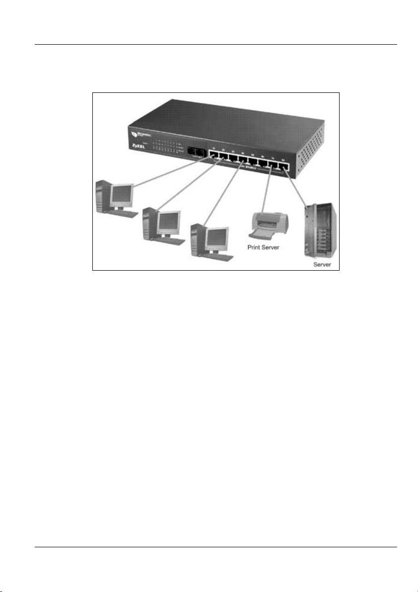
1.4.1 Standalone Workgroup
The switch can be used as a standalone switch to which computers, servers and printer
servers are directly connected to form a small workgroup.
Figure 1-1 Standalone Workgroup Example
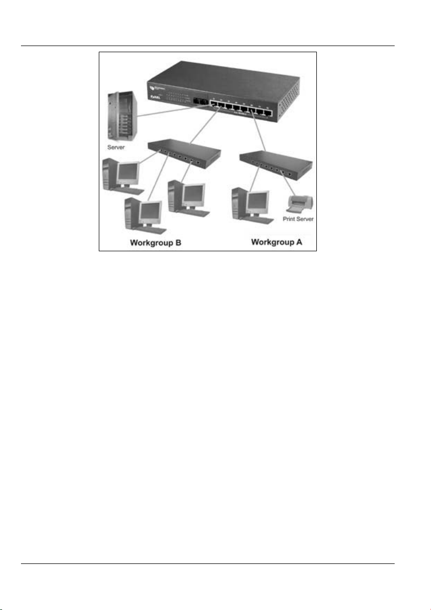
1.4.2 Bridging Application
For enterprise networks where large data broadcasts are constantly processed, this switch
is an ideal solution for department users to connect to the corporate backbone.
In the next illustration, two Ethernet switches with attached computers, print server and
local server, are all connected to the switch. All devices in this network can communicate
with each other through the switch and also access the server.
Getting to Know Your ES-2008 1-3
Dimension ES-2008 Ethernet Switch
Figure 1-2 Bridging Application Example
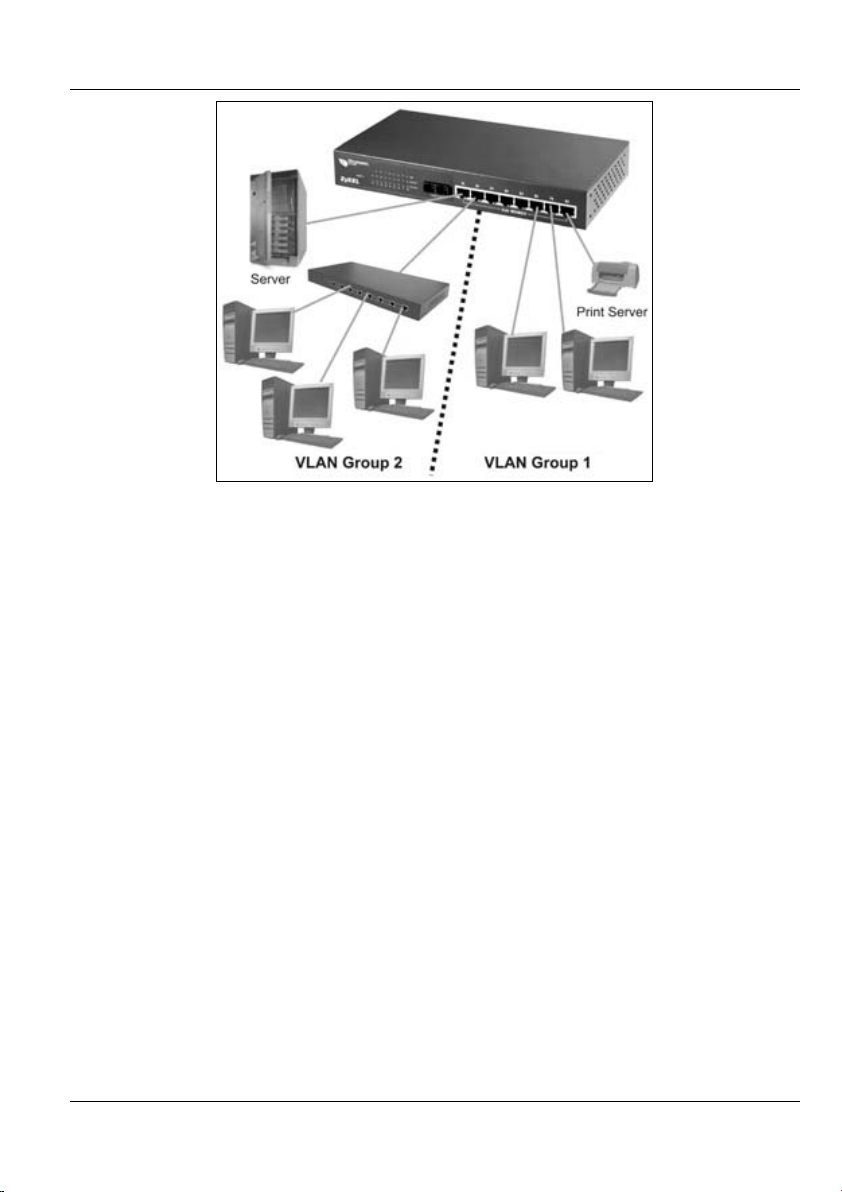
1.4.3 VLAN Application
VLAN (Virtual Local Area Network) allows a physical network to be partitioned into
multiple logical networks. Stations on a logical network belong to one group. A station
can belong to more than one group. With VLAN, a station cannot directly talk to or hear
from stations that are not in the same group(s); the traffic must first go through a router.
As well as security, VLANs also increase network performance by limiting broadcasts to
a smaller and more manageable logical broadcast domain. In traditional switched
environments, all broadcast packets go to each and every individual port. With VLAN,
broadcasts are confined to the members of the VLAN. Note that VLANs are
unidirectional - they only govern outgoing traffic.
Port-based VLANs are VLANs where the packet forwarding decision is based on the
destination MAC address and its associated port.
1-4 Getting to Know Your ES-2008
Dimension ES-2008 Ethernet Switch
Figure 1-3 VLAN Application Example
Getting to Know Your ES-2008 1-5

Dimension ES-2008 Ethernet Switch
Chapter 2
Hardware Description and
Installation
This chapter describes the switch hardware and installation
2.1 Hardware Installation
The switch is suitable for an office environment where it can be placed on a desktop.
Step 1. Make sure the switch is clean and dry.
Step 2. Attach the supply rubber feet to the bottom of the switch.
Step 3. Set the switch on a smooth and sturdy flat space strong enough to support the
weight of the switch and the connected cables. Make sure there is a power
outlet nearby.
Step 4. Make sure there is enough clearance around the switch to allow air circulation
and the attachment of cables and the power cord.
Do not block the ventilation holes. Leave space between switches
when stacking.
2.2 Hardware Connections
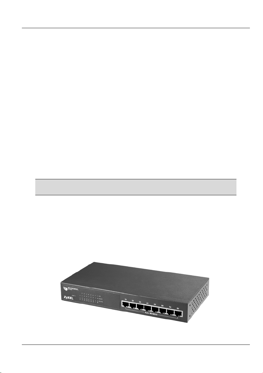
2.2.1 Front Panel
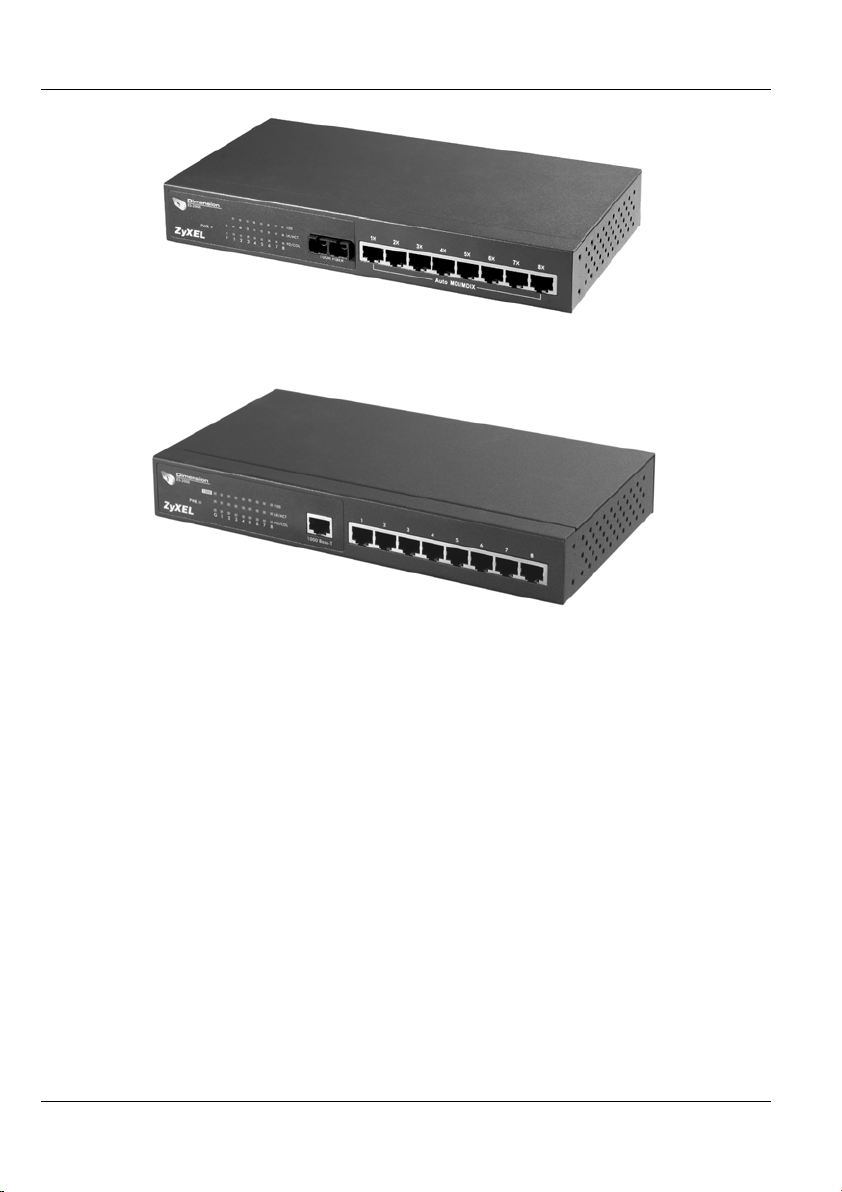
The front panel of the switch consists of eight auto-sensing, auto-negotiating 10/100BaseTX Ethernet RJ-45 ports and/or one 100Base-FX fiber or gigabit port.
The LEDs are also located on the front panel of the switch.
Figure 2-1 ES-2008
Hardware Description and Installation 2-1
Dimension ES-2008 Ethernet Switch
Figure 2-2 ES-2008 with Fiber Port
Figure 2-3 ES-2008 with Gigabit Port
2.2.2 The Ethernet Connections
Auto-Sensing 10/100Base-TX RJ-45 Ports (Auto MDI/MDIX)
The ES-2008 has eight auto-negotiating, auto-sensing 10/100Base-TX Ethernet RJ-45
ports. All these ports support auto-sensing, a built-in function that automatically
recognizes the type (straight/crossover) of the attached cable. This feature effectively
removes all wiring troubles caused by a cable type mismatch. Although a crossover cable
is usually required to cascade a switch to another switch, auto MDI/MDI-X lets you use a
normal straight cable to do the task.
Auto-Negotiating 10/100Base-TX RJ-45 Ports
The auto-negotiation feature allows the switch to detect the speed of incoming
transmission and adjust appropriately without manual intervention. It allows data transfers
of either 10 Mbps or 100 Mbps in either half-duplex or full-duplex mode depending on
your Ethernet network.
2-2 Hardware Description and Installation

Dimension ES-2008 Ethernet Switch
2.2.3 Network Cable Types
The following table describes the types of network cable used for the different connection
speeds. The fiber and gigabit ports are not available on all ES models.
Make sure the 10/100 Base-TX and/or 1000Base-T cable length
between connections does not exceed 100 meters (328 feet).
Table 2-1 Network Cable Types
SPEED NETWORK CABLE TYPE
10 Base-TX
100 Base-TX
1000BASE-T
100BASE-FX
(multi-mode)
100BASE-FX
(single-mode)
100Ω 2-pair UTP/STP Category 3, 4 or 5
100Ω 2-pair UTP/STP Category 5
100Ω 4-pair UTP/STP Category 5
50~62.5/125 micron multi-mode fiber-optics
8~10/125 micron single-mode fiber-optics
2.3 Front Panel LEDs
All the LEDs are found on the front panel of the switch to indicate real-time status of the
ports and the switch.
2.3.1 The PWR LED
The PWR LED on the front panel indicates whether the switch is receiving power.
Table 2-2 The Switch Power LED Description
LED COLOR STATUS DESCRIPTION
On The switch is receiving power. Power Green
Off The switch is not receiving power.
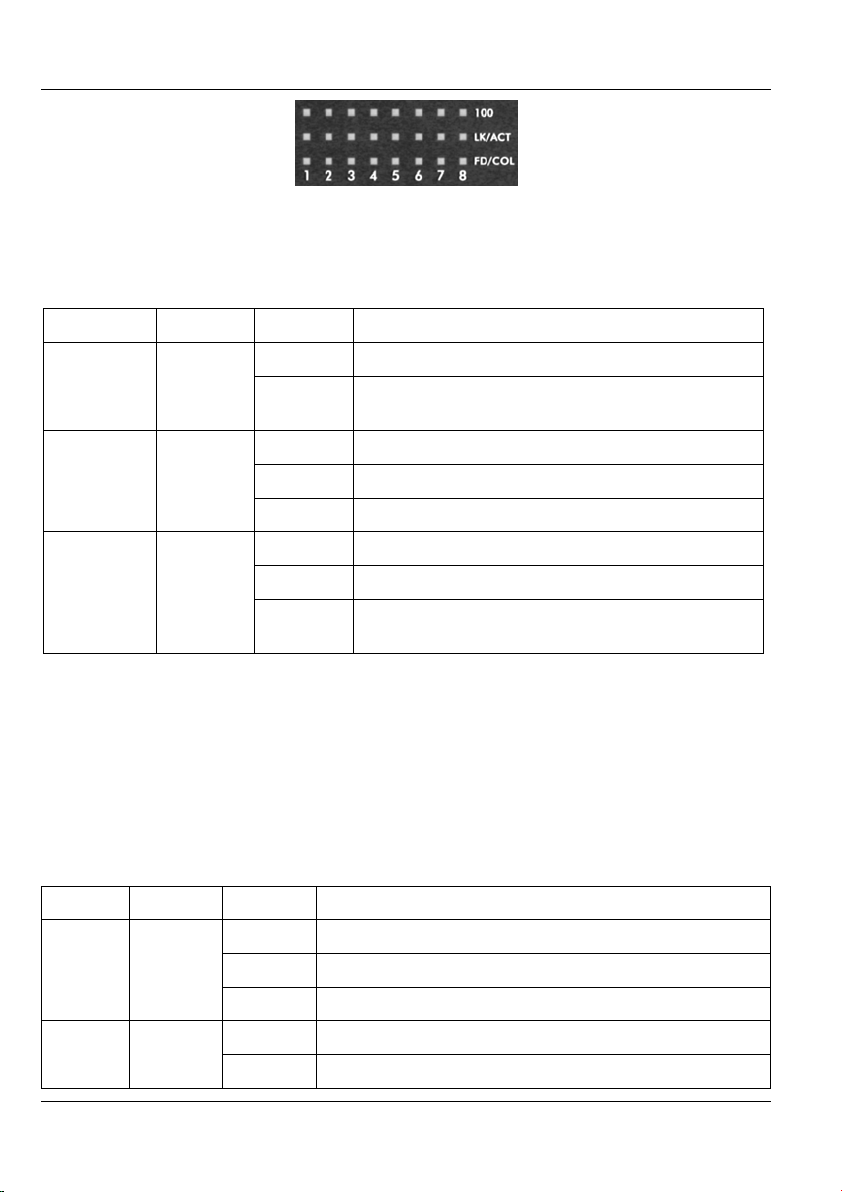
2.3.2 10/100M Ethernet Port LEDs
The LEDs for the 10/100M Ethernet ports give real-time system information and status.
Hardware Description and Installation 2-3
Dimension ES-2008 Ethernet Switch
Figure 2-4 Ethernet Port LEDs
The following table describes the LEDs for the Ethernet ports on the front panel.
Table 2-3 Ethernet Port LED Descriptions
LED COLOR STATUS DESCRIPTION
On The port is operating at 100Mbps. 100 Green
Off No device is attached or the port is operating at
10Mbps.
LK/ACT Green
FD/COL Orange
On The port is connecting with a device.
Blinking The port is receiving or transmitting data.
Off No device is attached.
On The port is operating in full-duplex mode.
Blinking Packet collisions are occurring
Off No device is attached or the device is in half-
duplex mode.
2.3.3 The Fiber Port
The 100FX fiber module is designed to extend the distance between the switch and other
Ethernet devices by up to 2 km using multi-mode fiber or 30 km using single-mode fibers.
The fiber port is not available on all switch models.
The LEDs provide real-time system status information of the fiber port. The following
table is a summary of LED status and meaning.
Table 2-4 100FX Module LED Descriptions
LED COLOR STATUS DESCRIPTION
LK/ACT Orange
2-4 Hardware Description and Installation
On The fiber port is connected to an Ethernet device.
Blinking This fiber port is transmitting data.
Off No data is being transmitted.
On The port is operating in full-duplex mode. FD/COL Orange
Blinking Packet collision is occurring on this port.
Dimension ES-2008 Ethernet Switch
Table 2-4 100FX Module LED Descriptions
LED COLOR STATUS DESCRIPTION
Off No device is attached or the port is operating in half-
duplex mode
2.3.4 The Gigabit Port
The gigabit port module is capable of transferring data at a speed up to 1000 mbps. The
gigabit port is not available on all switch models.
The following table describes the gigabit port LEDs.
Table 2-5 Gigabit Module LED Descriptions
LED COLOR STATUS DESCRIPTION
On The port is connected at 1000 Mbps. 1000 Green
Off The port is not connected at 1000 Mbps.
LK/ACT Orange
FD/COL Orange
On The fiber port is connected to an Ethernet device.
Blinking This fiber port is transmitting data.
Off No data is being transmitted.
On The port is operating in full-duplex mode.
Blinking Packet collision is occurring on this port.
Off No device is attached or the port is operating in half-
duplex mode
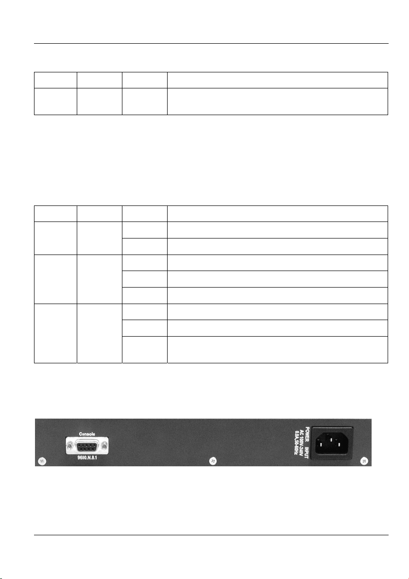
2.4 Rear Panel
The console port and the power socket are located on the rear panel as shown in the next
figure.
Figure 2-5 Rear Panel
Hardware Description and Installation 2-5

Dimension ES-2008 Ethernet Switch
2.4.1 Console Port
Local switch management is done through the console port. It requires a direct connection
between the switch and a computer via an RS-232 console cable. Refer to chapters on
SMT configurations.
2.5 Turning On the Switch
Connect one end of the power cord to the power receptacle on the rear panel of the switch
and the other end to the power outlet. Refer to the product specifications for the right
power source.
The PWR LED on the front panel turns on.
2-6 Hardware Description and Installation
 Loading...