

EMG5324-D10A
Wireless N GbE VoIP IAD with USB
Default Login Details
LAN IP
Address
User
Name
Password Admin password: 1234
www.zyxel.com
Version 3.00
Edition 1, 4/2012
https://192.168.1.1
Admin account: admin
User account: user
User password: 1234
www.zyxel.com
IMPORTANT!
READ CAREFULL Y
BEFORE USE.
KEEP THIS GUIDE
FOR FUTURE
REFERENCE.
Copyright © 2012
ZyXEL Communications Corporation

IMPORTANT!
READ CAREFULLY BEFORE USE.
KEEP THIS GUIDE FOR FUTURE REFERENCE.
Graphics in this book may differ slightly from the product due to differences in operating systems,
operating system versions, or if you installed updated firmware/software for your device. Every
effort has been made to ensure that the information in this manual is accurate.
Related Documentation
•Quick Start Guide
The Quick Start Guid shows how to connect the EMG5324-D10A and access the Web
Configurator. It information on setting up and configuring the EMG5324-D10A.
EMG5324-D10A User’s Guide2

Contents Overview
Contents Overview
User’s Guide .......................................................................................................................................15
Introduction .............................................................................................................................................17
Introducing the Web Configurator ...........................................................................................................23
Tutorials ..................................................................................................................................................31
Technical Reference ..........................................................................................................................73
Connection Status and System Info ........................................................................................................75
Broadband ....................................... ... .... ... ... ... ........................................................................................81
Wireless ..................................................................................................................................................95
Home Networking ..................................................................................................................................121
Routing .................................. ................................. ................................ ...............................................145
Quality of Service (QoS) .................... .... ... ... ... ................................................. ... ... ...............................149
Network Address Translation (NAT) ....... ................................... ....................................... .....................161
DNS Route ............... .... ... ... ... .... ............................................. ... ... .... ... ... ... ... .........................................171
Interface Group .....................................................................................................................................175
Firewall ...................................... ................................ ................................... .........................................177
MAC Filter .............................................................................................................................................185
Parental Control ....................................................................................................................................187
Certificates ............................................................................................................................................191
VPN .................................... ................................ .............................. .....................................................201
VoIP .......................................................................................................................................................221
Logs .....................................................................................................................................................243
Traffic Status ...................................... .... ... ............................................. ... ... .... ... ... ... ............................247
User Account ................................... ... .... ............................................. ... ... ... .... ... ... ...............................253
Remote MGMT ......................................................................................................................................255
The SNMP Screen ................................................................................................................................257
System ..................................................................................................................................................259
Time Setting ..........................................................................................................................................261
Log Setting ...........................................................................................................................................263
Firmware Upgrade ................................................................................................................................265
Backup/Restore .................................. .... ... ... ... ... ...................................................................................267
Diagnostic .............................................................................................................................................271
Troubleshooting ....................................................................................................................................273
Wall-mounting Instructions ....................................................................................................................281
EMG5324-D10A User’s Guide
3

Contents Overview
4
EMG5324-D10A User’s Guide

Table of Contents
Table of Contents
Contents Overview ..............................................................................................................................3
Table of Contents .................................................................................................................................5
Part I: User’s Guide .........................................................................................15
Chapter 1
Introduction.........................................................................................................................................17
1.1 Overview ................................................ ... ............................................. .... ... ... ... .... ..........................17
1.2 Applications for the Device ..................... ... ... .... ... ............................................. ... .... ... ... ....................17
1.2.1 Internet Access ....................... ... ... ... ... .............................................. ... ... ... .... ... .......................17
1.2.2 VoIP Features ........ .... ... ... ... .............................................. ... ... ... ... .... .......................................18
1.2.3 Wireless Connection ........ ... .... ... ............................................. ... ... .... ... ... ... .... ... ... ... .................18
1.3 The WLAN Button .................................................. ... .... ... ... ... .... ... ....................................................18
1.4 Ways to Manage the Device ......................................... ... ... ... .... ... ... .................................................20
1.5 Good Habits for Managing the Device ..............................................................................................20
1.6 LEDs (Lights) ............... ... .... ... ... ... .... ............................................. ... ... ... .... ... ....................................20
1.7 The RESET Button ........................... ... ... ... ... .... ... ... ............................................. .... ... ... ....................22
Chapter 2
Introducing the Web Configurator ....................................................................................................23
2.1 Overview ................................................ ... ............................................. .... ... ... ... .... ..........................23
2.1.1 Accessing the Web Configurator .............................................................................................23
2.2 The Web Configurator Layout .......... ... ... ... ... .... ... ..............................................................................25
2.2.1 Title Bar ........................ ... ... .... ... ... ............................................. ... .... ... ....................................25
2.2.2 Main Window ............................................................. ... .... .......................................................26
2.2.3 Navigation Panel ... .... ... ... ... .... ... ... ... ... .... .................................................................................26
Chapter 3
Tutorials...............................................................................................................................................31
3.1 Overview ................................................ ... ............................................. .... ... ... ... .... ..........................31
3.2 How to Set up a Wireless Network ............... ....... ...... ....... ...... ....... ...... ....... ... ...... ....... ...... .................31
3.2.1 Example Parameters .............................................................. ... ..............................................31
3.2.2 Configuring the AP .............................................. ... ... ... .... .......................................................32
3.2.3 Configuring the Wireless Client ...............................................................................................33
3.3 Setting Up NAT Port Forwarding ............................ ................................................. ..........................38
3.4 How to Make a VoIP Call ..................................................................................................................39
3.4.1 VoIP Calls With a Registered SIP Account ..............................................................................40
EMG5324-D10A User’s Guide
5

Table of Contents
3.5 Using the File Sharing Feature ........................ ... ... ... .... ... ... ... .... ... ... ... ..............................................42
3.5.1 Set Up File Sharing .................................................................................................................43
3.5.2 Access Yo ur Shared Files From a Computer ..........................................................................44
3.6 Using the Media Server Feature ......................................................................................................44
3.6.1 Configuring the Device ........................... .................................................................................45
3.6.2 Using Windows Media Player ................. ... ... ... .... ... ... ... .... .......................................................45
3.6.3 Using a Digital Media Adapter ................................................................ ... .... ... ... ... ... .... ..........48
3.7 Using the Print Server Feature ............................ ...... ....... ... ....... ...... ...... ....... ...... ....... ...... .................50
3.8 Configuring the MAC Address Filter ..................................................................................................65
3.9 Configuring Static Route for Routing to Another Network ............................................. ....................66
3.10 Configuring QoS Queue and Class Setup ......................................................................................68
3.11 Access the Device Using DDNS .....................................................................................................71
3.11.1 Registering a DDNS Account on www.dyndns.org ................................................................72
3.11.2 Configuring DDNS on Your Device ........................................................................................72
3.11.3 Testing the DDNS Setting ......................................................................................................72
Part II: Technical Reference............................................................................73
Chapter 4
Connection Status and System Info .................................................................................................75
4.1 Overview ................................................ ... ............................................. .... ... ... ... .... ..........................75
4.2 The Connection Status Screen .........................................................................................................75
4.3 The System Info Screen ...................................................................................... .... ... ... ... .................77
Chapter 5
Broadband...........................................................................................................................................81
5.1 Overview ................................................ ... ............................................. .... ... ... ... .... ..........................81
5.1.1 What Yo u Can Do in this Chapter ............................................................................................82
5.1.2 What You Need to Know .................................. .... ... ... ..............................................................82
5.1.3 Before You Begin ... .... ... ... ... .... ... ... ... ........................................................................................84
5.2 The Broadband Screen .....................................................................................................................84
5.2.1 Add/Edit Internet Connection ........... ... .... ... ... ................................................. ... ... ... .................85
5.3 The 3G Backup Screen ... .... ... ... ... .............................................. ... ... ... ... .... ... ... ... .... ... .......................89
5.4 Technical Reference ............ ................................................ ... .... .......................................................91
Chapter 6
Wireless...............................................................................................................................................95
6.1 Overview ................................................ ... ............................................. .... ... ... ... .... ..........................95
6.1.1 What Yo u Can Do in this Chapter ............................................................................................95
6.1.2 Wireless Network Overview .... ... ... ... ... .... ... ... ...........................................................................95
6.1.3 Before You Begin ... .... ... ... ... .... ... ... ... ........................................................................................97
6
EMG5324-D10A User’s Guide

Table of Contents
6.2 The Wireless General Screen ................................................................... ... ... ... .... ... ... ... ... ..............97
6.2.1 No Security ............................................................. ... ... ...........................................................98
6.2.2 Basic (Static WEP/Shared WEP Encryption) ...........................................................................99
6.2.3 More Secure (WPA(2)-PSK) ..................................................................................................101
6.2.4 WPA(2) Authentication .................................................................. .... ... ... ... .... ... ... ... ... ............102
6.3 The More AP Screen .................................... .... ... ... ... .... ... ... ... .... .....................................................103
6.3.1 Edit More AP ............................................. ... ............................................. .... ... ... ... ...............104
6.4 The WPS Screen ......................... .... ... ... ... ... .... ................................................ ... .... ........................105
6.5 The WMM Screen ...........................................................................................................................107
6.6 Scheduling Screen .........................................................................................................................108
6.7 The Channel Status Screen ................ ... ... ... .... ... ... ... ................................................. ... ... ...............109
6.8 Technical Reference ............ ................................................ ... .... .....................................................109
6.8.1 Additional Wireless Terms .....................................................................................................110
6.8.2 Wireless Security Overview ...................................................................................................110
6.8.3 Signal Problems . ...................................................................................................................112
6.8.4 BSS ........................................ ...............................................................................................113
6.8.5 WiFi Protected Setup (WPS) .................................................................................................113
Chapter 7
Home Networking.............................................................................................................................121
7.1 Overview ................................................ ... ............................................. .... ... ... ... .... ........................121
7.1.1 What Yo u Can Do in this Chapter ..........................................................................................121
7.1.2 What You Need To Know ........................... ... ............................................. .... ... ... ... ... .... ... .....121
7.2 The LAN Setup Screen ...................................................................................................................124
7.3 The Static DHCP Screen .................................................................. ... ... .... ... ... ... .... ... .....................125
7.3.1 Before You Begin ... .... ... ... ... .... ... ... ... ......................................................................................125
7.4 The UPnP Screen ...........................................................................................................................127
7.5 The File Sharing Screen ........................... ... .... ... ... ... .... ... ... ... .... ... ... ...............................................127
7.5.1 Before You Begin ... .... ... ... ... .... ... ... ... ......................................................................................128
7.5.2 Add/Edit File Sharing ....................... ... .... ... ... ... .... ... ... ... .........................................................129
7.6 The Media Server Screen ............................................................................................................... 130
7.7 The Printer Server Screen ..............................................................................................................131
7.7.1 Before You Begin ... .... ... ... ... .... ... ... ... ......................................................................................131
7.8 Technical Reference ............ ................................................ ... .... .....................................................132
7.9 Installing UPnP in Windows Example .............................................................................................136
7.10 Using UPnP in Windows XP Example .............. ... ... .... ... ... ... .... ... ... ... ... .........................................139
Chapter 8
Routing ..............................................................................................................................................145
8.1 Overview .................................................. ... .............................................. ... ... ... .... ........................145
8.2 Configuring Static Route ............................................... ... ... ... .........................................................146
8.2.1 Add/Edit Static Route ...........................................................................................................147
EMG5324-D10A User’s Guide
7

Table of Contents
Chapter 9
Quality of Service (QoS)...................................................................................................................149
9.1 Overview ................................................ ... ............................................. .... ... ... ... .... ........................149
9.1.1 What Yo u Can Do in this Chapter ..........................................................................................149
9.1.2 What You Need to Know .................................. .... ... ... ............................................................149
9.2 The QoS General Screen ................................... ... ... .... ... ... ... .... .....................................................150
9.3 The Queue Setup Screen ...............................................................................................................151
9.3.1 Add/Edit a QoS Queue ................................................................ .........................................152
9.4 The Class Setup Screen ...............................................................................................................153
9.4.1 Add/Edit QoS Class ........................... .... ... ... ... ......................................................................155
9.5 The QoS Monitor Screen ...............................................................................................................158
9.6 QoS Technical Reference ...............................................................................................................159
9.6.1 IEEE 802.1Q Tag ...................................................................................................................159
9.6.2 IP Precedence ........................................................... ... .... ... ... ...............................................160
9.6.3 DiffServ ...................... ............................................. ... ... .... ... ..................................................160
Chapter 10
Network Address Translation (NAT)................................................................................................161
10.1 Overview ......................................................................................................................................161
10.1.1 What You Can Do in this Chapter ........................................................................................161
10.1.2 What You Need To Know .................. .......................................... .........................................161
10.2 The Port Forwarding Screen ........................................................................................................162
10.2.1 The Port Forwarding Screen ...............................................................................................163
10.2.2 The Port Forwarding Edit Screen ........................................................................................164
10.3 The DMZ Screen ........ ... ................................................................................................................165
10.4 The Sessions Screen ................. .... ... ... ... ... .... ... ... ... ................................................. ... ... ...............165
10.5 The Address Mapping Screen .................... .............................................. ... ... ... .... ........................166
10.5.1 Add/Edit Address Mapping Rule ........................ ...................... ....................... .....................167
10.6 The ALG Screen ...........................................................................................................................168
10.7 Technical Reference .......... ...... ....... ... ...... ....... ...... ....... ...... ....... ...... ...... .... ...... ....... ...... ..................168
10.7.1 NAT Definitions ....................................................................................................................168
10.7.2 What NAT Does ...................................................................................................................169
10.7.3 How NAT Works ..................................................................................................................169
Chapter 11
DNS Route.........................................................................................................................................171
11.1 Overview .......................................................................................................................................171
11.2 The DNS Route Screen .................................................................................................................172
11.2.1 Add/Edit DNS Route Edit ....................................................................................................172
Chapter 12
Interface Group.................................................................................................................................175
12.1 Overview .......................................................................................................................................175
8
EMG5324-D10A User’s Guide

Table of Contents
12.2 The Interface Group Screen ........................... ... ............................................. ... .... ... .....................175
12.2.1 Interface Group Configuration ............................................................................................. 176
Chapter 13
Firewall ..............................................................................................................................................177
13.1 Overview .......................................................................................................................................177
13.1.1 What You Can Do in this Chapter ........................................................................................177
13.1.2 What You Need to Know ....................................... ............. ............. ............. ............ ............178
13.2 The General Screen ............ ... ... .... ...............................................................................................178
13.3 The Services Screen ......... ... ... ................................................. ... ... ...............................................179
13.3.1 Add/Edit a Service ..............................................................................................................180
13.4 The Access Control Screen ..........................................................................................................181
13.4.1 Add/Edit an ACL Rule ............................... ....................... ................... ....................... ........182
13.5 The DoS Screen ............................................................................................................................183
13.6 Firewall Technical Reference ........................................................................................................183
13.6.1 Guidelines For Enhancing Security With Your Firewall .......................................................184
13.6.2 Security Considerations ........................... ....................... ...................... ....................... ........184
Chapter 14
MAC Filter..........................................................................................................................................185
14.1 Overview .......................................................................................................................................185
14.1.1 What You Need to Know ....................................... ............. ............. ............. ............ ............185
14.2 The MAC Filter Screen ..................................................................................................................185
Chapter 15
Parental Control................................................................................................................................187
15.1 Overview .......................................................................................................................................187
15.2 The Parental Control Screen ............................. ............. ............. ............. ............. ............ ............187
15.2.1 Add/Edit a Parental Control Rule .........................................................................................188
Chapter 16
Certificates........................................................................................................................................191
16.1 Overview .......................................................................................................................................191
16.1.1 What You Can Do in this Chapter ........................................................................................191
16.1.2 What You Need to Know ....................................... ............. ............. ............. ............ ............191
16.1.3 Verifying a Certificate ...........................................................................................................192
16.2 Local Certificates ..................................... ... .... ... ... ... .... ... ... ... .... .....................................................193
16.3 Trusted CA ..................................................................................................................................195
16.4 Trusted CA Import .......................................................................................................................195
16.5 View Certificate .............................................................................................................................196
16.6 VPN Certificates ............................................................................................................................197
16.6.1 Import Certificate .................................................................................................................198
EMG5324-D10A User’s Guide
9

Table of Contents
Chapter 17
VPN ....................................................................................................................................................201
17.1 Overview .......................................................................................................................................201
17.1.1 What You Can Do in the VPN Screens ................................................................................201
17.1.2 What You Need to Know About IPSec VPN ........................................................................201
17.1.3 Before You Begin .................................................................................................................203
17.2 VPN Setup Screen .......................................................................................................................203
17.3 The VPN Edit Screen ....................... ... ... ... .... ... ... ... .... ... ... ............................................................205
17.4 Configuring Advanced Settings ....................................................................................................208
17.5 Viewing SA Monitor ......................................................................................................................210
17.6 IPSec VPN Technical Reference ...................................................................................................210
17.6.1 IPSec Architecture ...................... .................................................... .....................................211
17.6.2 IPSec and NAT ....................................................................................................................211
17.6.3 VPN, NAT, and NAT Traversal .............................................. ...............................................212
17.6.4 Encapsulation ......................................................................................................................213
17.6.5 IKE Phases .........................................................................................................................214
17.6.6 Negotiation Mode ................................................................................................................215
17.6.7 Remote DNS Server ............................................................................................................215
17.6.8 ID Type and Content ................................................ ....................... ...................... ...............216
17.6.9 Pre-Shared Key ...................................................................................................................217
17.6.10 Diffie-Hellman (DH) Key Groups ........................................................................................217
17.6.11 Telecommuter VPN/IPSec Examples ........ ... .... ... ... ... ......................................................... 217
Chapter 18
VoIP ....................................................................................................................................................221
18.1 Overview .......................................................................................................................................221
18.1.1 What You Can Do in this Chapter ........................................................................................221
18.1.2 What You Need to Know ....................................... ............. ............. ............. ............ ............221
18.1.3 Before You Begin .................................................................................................................222
18.2 The SIP Service Provider Screen ................................................................................................223
18.3 The SIP Account Screen ...............................................................................................................226
18.3.1 Add/Edit SIP Account ..........................................................................................................227
18.4 Multiple SIP Accounts ...................................................................................................................229
18.5 Phone Screen ..............................................................................................................................230
18.5.1 Edit Phone Device ...............................................................................................................230
18.6 The Phone Region Screen ......... .... ... ... ... ................................................. ... ... ... .... ... ... ... ... ............231
18.7 The Call Rule Screen ....................................................................................................................232
18.8 Technical Reference .......... ...... ....... ... ...... ....... ...... ....... ...... ....... ...... ...... .... ...... ....... ...... ..................233
18.8.1 VoIP .....................................................................................................................................233
18.8.2 SIP ......................................................................................................................................233
18.8.3 Quality of Service (QoS) .......................... ....................................................... .....................238
18.8.4 Phone Services Overview ...................................................................................................239
10
EMG5324-D10A User’s Guide

Table of Contents
Chapter 19
Logs ..................................................................................................................................................243
19.1 Overview ......................................................................................................................................243
19.1.1 What You Can Do in this Chapter ........................................................................................243
19.1.2 What You Need To Know .................. .......................................... .........................................243
19.2 The System Log Screen ................................................................................................................244
19.3 The Phone Log Screen .................................................................................................................245
19.4 The VoIP Call History Screen ........................................................................................................245
Chapter 20
Traffic Status.....................................................................................................................................247
20.1 Overview .......................................................................................................................................247
20.1.1 What You Can Do in this Chapter ........................................................................................247
20.2 The WAN Status Screen ...............................................................................................................247
20.3 The LAN Status Screen .................................................................................................................248
20.4 The NAT Status Screen ..................................................... ... .... ... ... ... ... .........................................249
20.5 The 3G Backup Status Screen ....................................................... ...............................................250
20.6 The VoIP Status Screen ................................................................................................................251
Chapter 21
User Account ....................................................................................................................................253
21.1 Overview .......................................................................................................................................253
21.2 The User Account Screen ................. ... ... ... .... ... ... ... .... ... ... ... .... ... ... ... ... .... .....................................253
Chapter 22
Remote MGMT...................................................................................................................................255
22.1 Overview .......................................................................................................................................255
22.1.1 What You Need to Know ....................................... ............. ............. ............. ............ ............255
22.2 The Remote MGMT Screen ....................... ................................................................. ..................256
Chapter 23
The SNMP Screen.............................................................................................................................257
Chapter 24
System...............................................................................................................................................259
24.1 Overview .......................................................................................................................................259
24.1.1 What You Need to Know ....................................... ............. ............. ............. ............ ............259
24.2 The System Screen .................... .... ... ... ............................................. ... .... ... ..................................259
Chapter 25
Time Setting......................................................................................................................................261
25.1 Overview .......................................................................................................................................261
25.2 The Time Setting Screen .............................................................................................................261
EMG5324-D10A User’s Guide
11

Table of Contents
Chapter 26
Log Setting .......................................................................................................................................263
26.1 Overview ......................................................................................................................................263
26.2 The Log Setting Screen ................................................................................................................263
Chapter 27
Firmware Upgrade ............................................................................................................................265
27.1 Overview .......................................................................................................................................265
27.2 The Firmware Upgrade Screen ............................ .................................... .....................................265
Chapter 28
Backup/Restore ................................................................................................................................267
28.1 Overview .......................................................................................................................................267
28.2 The Backup/Restore Screen .........................................................................................................267
28.3 The Reboot Screen .......................................................................................................................269
Chapter 29
Diagnostic .........................................................................................................................................271
29.1 Overview .......................................................................................................................................271
29.2 The Ping/TraceRoute Screen ..................... .... ............................................. ... ... .... ... ... ... ...............271
29.3 The DSL Line Screen ....................................................................................................................272
Chapter 30
Troubleshooting................................................................................................................................273
30.1 Overview .......................................................................................................................................273
30.2 Power, Hardware Connections, and LEDs ........................ ... .... ... ... ... ............................................273
30.3 Device Access and Login ..............................................................................................................274
30.4 Internet Access .............................................................................................................................276
30.5 Wireless Internet Access ...............................................................................................................277
30.6 Phone Calls and VoIP ...................................................................................................................278
30.7 USB Device Connection ................................................................................................................279
30.8 UPnP .............................................................................................................................................279
Chapter 31
Wall-mounting Instructions .............................................................................................................281
Appendix A IP Addresses and Subnetting.......................................................................................283
Appendix B Setting Up Your Computer’s IP Address......................................................................293
Appendix C Pop-up Windows, JavaScript and Java Permissions...................................................323
Appendix D Wireless LANs..............................................................................................................333
Appendix E Common Services........................................................................................................353
12
EMG5324-D10A User’s Guide

Table of Contents
Appendix F IPv6...............................................................................................................................357
Appendix G Legal Information.........................................................................................................369
Index ..................................................................................................................................................373
EMG5324-D10A User’s Guide
13

Table of Contents
14
EMG5324-D10A User’s Guide

PART I
User’s Guide
15

16
1.1 Overview
LAN
PPPoE
IPoE
WAN
Ethernet
Bridge
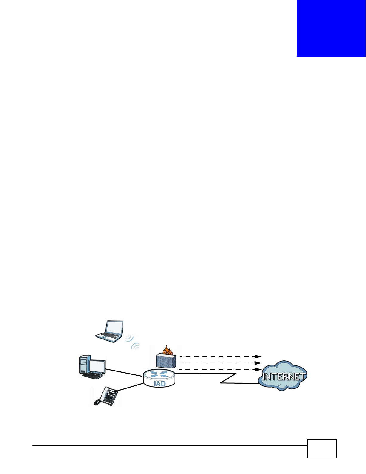
The Device is an Ethernet integrated access device (IAD), which provides Voice over IP (VoIP)
communication capabilities to allow you to use a traditional analog telephone to make Internet
calls. By integrating all of these features, you are provided with ease of installation and high-speed,
shared Internet access. The Device is also a complete security solution with a robust firewall based
on Stateful Packet Inspection (SPI) technology and Denial of Service (DoS).
When the Device does not have power, only the phone connected to the
PHONE port 1 can be used for making calls. Ensure you know which
phone this is, so that in case of emergency you can make outgoing calls.
CHAPTER 1
Introduction
1.2 Applications for the Device
Here are some example uses for which the Device is well suited.
1.2.1 Internet Access
If you have another broadband modem or router av ailable, you can connect the WAN port to the it.
This way , y ou can access the Internet via an Ethernet connection and still use the QoS, Firewall and
VoIP functions on the Device.
Computers can connect to the Device’s LAN ports (or wirelessly).
Figure 1 Device’s Internet Access Application
EMG5324-D10A User’s Guide 17
Chapter 1 Introduction
PSTN
LAN
WLAN
WAN
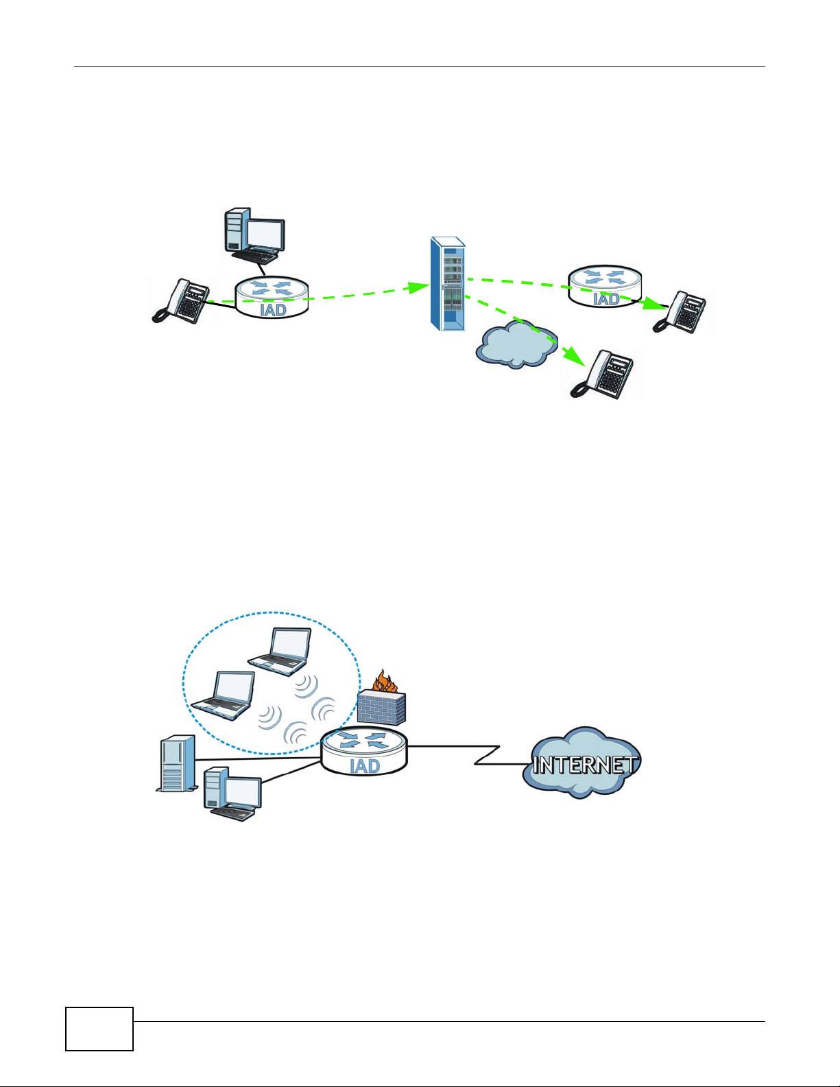
1.2.2 VoIP Features
You can register 1 SIP (Session Initiation Protocol) profile (2 accounts for that profile) and use the
Device to make and receive VoIP telephone calls:
Figure 2 Device’s VoIP Application
The Device sends your call to a VoIP service provider’s SIP server which forwards your calls to
either VoIP or PSTN phones.
1.2.3 Wireless Connection
By default, the wireless LAN (WLAN) is enabled on the Device. Once Wireless is enabled, IEEE
802.11b/g/n compliant clients can wirelessly connect to the Device to access network resources.
You can set up a wireless network with WPS (WiFi Protected Setup) or manually add a client to your
wireless network.
Figure 3 Wireless Connection Application
1.3 The WLAN Button
You can use the WLAN ON/OFF button on top of the device to turn the wireless LAN on or off. You
can also use it to activate WPS in order to quickly set up a wireless network with strong security.
18
EMG5324-D10A User’s Guide

Chapter 1 Introduction
Turn the Wireless LAN On or Off
1 Make sure the POWER LED is on (not blinking).
2 Press the WLAN ON/OFF button for one second and release it. The WLAN/WPS LED should change
from on to off or vice versa.
Activate WPS
1 Make sure the POWER LED is on (not blinking).
2 Press the WLAN ON/OFF button for more than five seconds and release it. Press the WPS button on
another WPS -enabled device within range of the Device. The WLAN/WPS LED should flash while
the Device sets up a WPS connection with the wireless device.
Note: You must activate WPS in the Device and in another wireless device within two
minutes of each other. See Chapter 6 on page 113 for more information.
EMG5324-D10A User’s Guide
19
Chapter 1 Introduction
1.4 Ways to Manage the Device
Use any of the following methods to manage the Device.
• Web Configurator. This is recommended for everyday management of the Device using a
(supported) web browser.
• FTP for firmware upgrades and configuration backup/restore.
1.5 Good Habits for Managing the Device
Do the following things regularly to make the Device more secure and to manage the Device more
effectively.
• Change the password. Use a password that’s not easy to guess and that consists of different
types of characters, such as numbers and letters.
• Write down the password and put it in a safe place.
• Back up the configuration (and make sure you know how to restore it). Restoring an earlier
working configuration may be useful if the device becomes unstable or even crashes. If you
forget your password to access the Web Configurator, you will have to reset the Device to its
factory default settings. If you backed up an earlier configuration file, you would not have to
totally re-configure the Device. You could simply restore your last configuration. Keep in mind
that backing up a configuration file will not back up passwords used to set up PPPoE and VoIP.
Write down any information your ISP provides you.
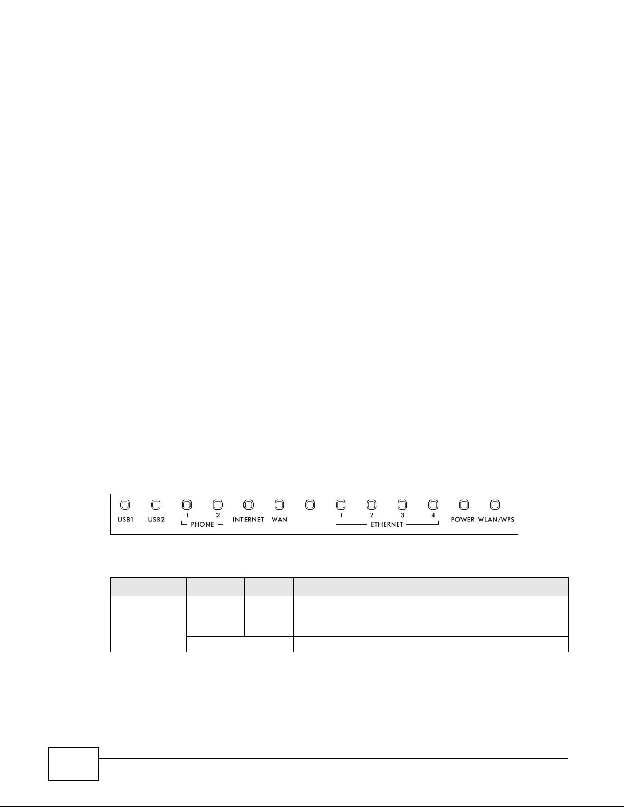
1.6 LEDs (Lights)
The following graphic displays the labels of the LEDs.
Figure 4 LEDs on the Top of the Device
None of the LEDs are on if the Device is not receiving power.
Table 1 LED Descriptions
LED COLOR STATUS DESCRIPTION
USB1-2 Green On The Device recognizes a USB connection but there is no traffic.
Off The Device does not detect a USB connection.
Blinking The Device is sending/receiving data to /from the USB device
connected to it.
20
EMG5324-D10A User’s Guide
Chapter 1 Introduction
Table 1 LED Descriptions (continued)
LED COLOR STATUS DESCRIPTION
PHONE1-2 Green On A SIP account is registered for the phone port.
Blinking A telephone connected to the phone port has its receiver off of
the hook or there is an incoming call.
Orange On A SIP account is registered for the phone port and there is a
voice message in the corresponding SIP account.
Blinking A telephone connected to the phone port has its receiver off of
Off The phone port does not have a SIP account registered.
INTERNET Green On The Device has an IP connection but no traffic.
Blinking The Device is sending or receiving IP traffic.
Off The Device does not have an IP connection.
Red On The Device attempted to make an IP connection but failed.
WAN Green On This light applies when the Device is in Ethernet W AN mode. Th e
Blinking The Device is sending or receiving data to/from the Ethernet
Off The Device does not have an Ethernet connection with the WAN.
ETHERNET1-4 Green
(Giga
Ethernet)
Orange
(Fast
Ethernet)
Off The Device does not have an Ethernet connection with the LAN.
POWER Green On The Device is receiving power and ready for use.
Red On The Device detected an error while self-testing, or there is a
Off The Device is not receiving power.
WLAN/WPS Green On The wireless network is activated and is operating in IEEE 802.11
Orange On The WPS is configured.
Off The wireless network is not activated.
On The Device has a successful 1000 Mbps Ethernet connection with
Blinking The Device is sending or receiving data to/from the LAN at 1000
On The Device has a successful 10/100 Mbps Ethernet connection
Blinking The Device is sending or receiving data to/from the LAN at 10/
Blinking The Device is self-testing.
Blinking The Device is communicating with other wireless clients.
Blinking The Device is setting up a WPS connection.
the hook and there is a voice message in the corresponding SIP
account.
Your device has a W AN IP address (eithe r stat ic or assigned b y a
DHCP server), PPP negotiation was successfully comple ted (if
used).
Possible causes are no response from a DHCP server, no PPPoE
response, PPPoE authentication failed.
Device has an Ethernet connection with a device on the WAN.
WAN.
a device on the Local Area Network (LAN).
Mbps.
with a device on the Local Area Network (LAN).
100 Mbps.
device malfunction.
“b”, “g” or “n” mode.
Refer to the Quick Start Guide for information on hardware connections.
EMG5324-D10A User’s Guide
21

Chapter 1 Introduction
1.7 The RESET Button
If you forget your password or cannot access the web configurator, you will need to use the RESET
button at the back of the device to reload the factory-default configuration file. This means that y ou
will lose all configurations that you had previously and the passwords will be reset to the defaults.
1 Make sure the POWER LED is on (not blinking).
2 T o set the device back to the factory default settings, press the RESET button for 5 seconds or until
the POWER LED begins to blink and then release it. When the POWER LED begins to blink, the
defaults have been restored and the device restarts.
22
EMG5324-D10A User’s Guide
2.1 Overview
The web configurator is an HTML-based management interface that allows easy device setup and
management via Internet browser. Use Internet Explorer 6.0 and later versions, Mozilla Firefox 3
and later versions, or Safari 2.0 and later versions. The recommended screen resolution is 1024 by
768 pixels.
In order to use the web configurator you need to allow:
• Web browser pop-up windows from your device. Web pop -up blocking is enabled by default in
Windows XP SP (Service Pack) 2.
• JavaScript (enabled by default).
• Java permissions (enabled by default).
CHAPTER 2
Introducing the Web Configurator
See Appendix C on page 323 if you need to make sure these functions are allowed in Internet
Explorer.
2.1.1 Accessing the Web Configurator
1 Make sure your Device hardware is properly connected (refer to the Quick Start Guide).
2 Launch your web browser.
3 Type "192.168.1.1" as the URL.
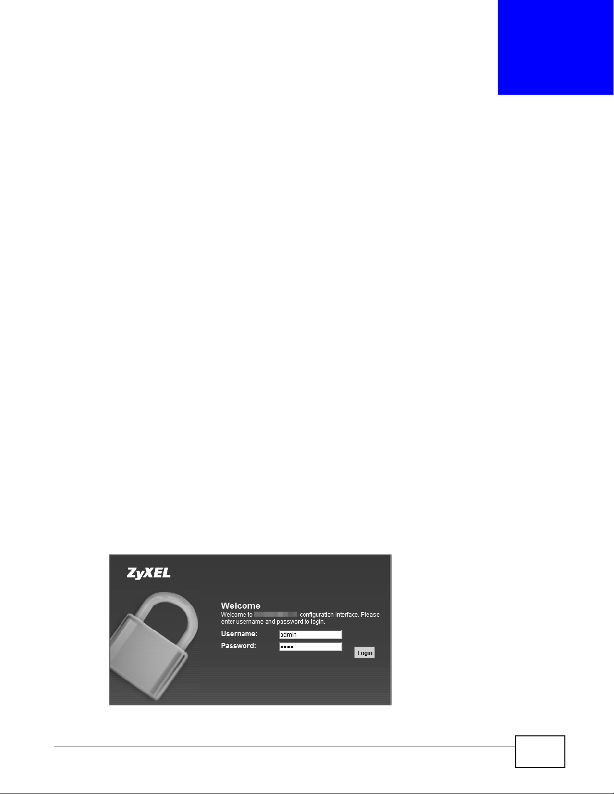
4 A password screen displays. Type “admin” as the default Username and “1234” as the default
password to access the device’s W eb Configur ator. Click Login. If you have changed the password,
enter your password and click Login.
Figure 5 Password Screen
EMG5324-D10A User’s Guide 23
Chapter 2 Introdu cing the Web Configurator
Note: For security reasons, the Device automatically logs you out if you do not use the
web configurator for five minutes (default). If this happens, log in again.
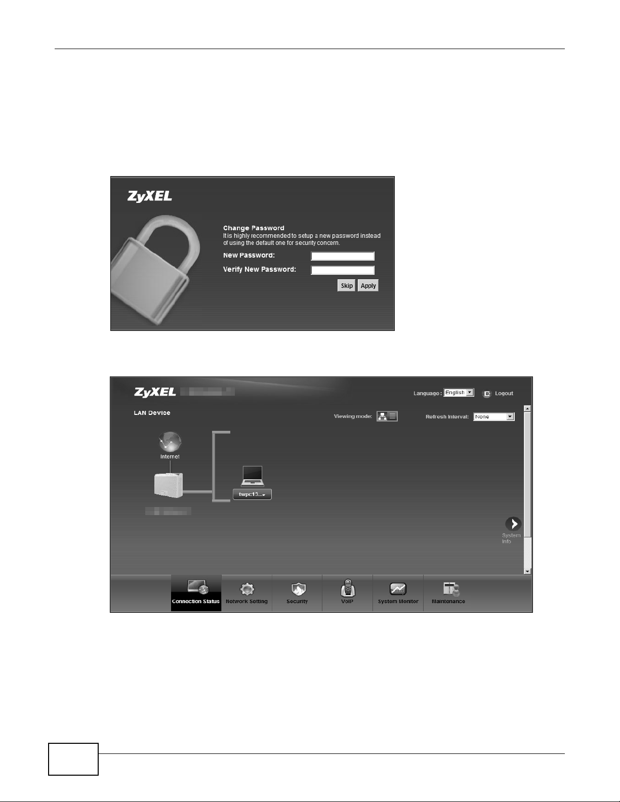
5 The following screen displays if you have not yet changed your password. It is strongly
recommended you change the default password. Enter a new password, retype it to confirm and
click Apply; alternatively click Skip to proceed to the main menu if you do not want to change the
password now.
Figure 6 Change Password Screen
6 The Connection Status screen appears.
Figure 7 Connection Status
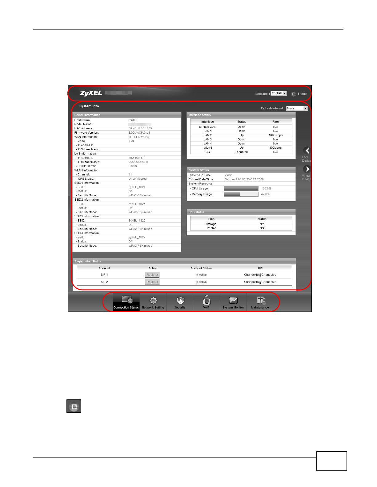
7 Click System Info to display the System Info screen, where you can view the Device’s interface
and system information.
24
EMG5324-D10A User’s Guide
2.2 The Web Configurator Layout
B
C
A
a
b
Click Connection Status > System Info to show the following screen.
Figure 8 Web Configurator Layout
Chapter 2 Introducing the Web Configurator
As illustrated above, the main screen is divided into these parts:
• A - title bar
• B - main window
• C - navigation panel
2.2.1 Title Bar
The title bar shows the following icon in the upper right corner.
Click this icon to log out of the web configurator.
EMG5324-D10A User’s Guide
25
Chapter 2 Introdu cing the Web Configurator
2.2.2 Main Window
The main window displays information and configuration fields. It is discussed in the rest of this
document.
After you click System Info on the Connection Status screen, the System Info screen is
displayed. See Chapter 4 on page 77 for more information about the System Info screen.
If you click LAN Device on the System Info screen (a in Figure 8 on page 25), the Connection
Status screen appears. See Chapter 4 on page 75 for more information about the Connection
Status screen.
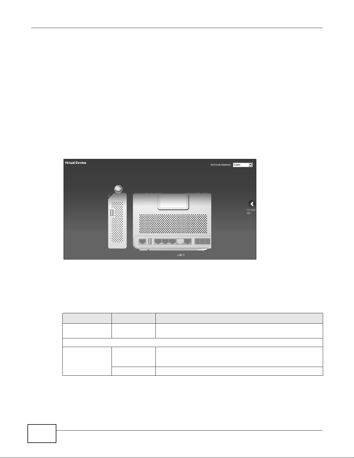
If you click Virtual Device on the System Info screen (b in Figure 8 on page 25), a visual graphic
appears, showing the connection status of the Device’s ports. The connected ports are in color and
disconnected ports are gray.
Figure 9 Virtual Device
2.2.3 Navigation Panel
Use the menu items on the navigation panel to open screens to configure Device features. The
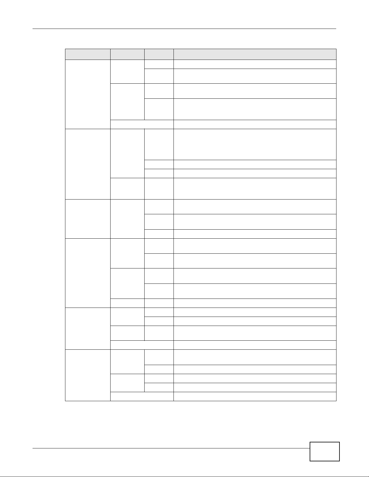
following table describes each menu ite m.
Table 2 Navigation Panel Summary
LINK TAB FUNCTION
Connection Status This screen shows the network status of the Device and computers/
Network Setting
Broadband Broadband Use this screen to view and modify your WAN interface. You can also
3G Backup Use this screen to configure the 3G WAN connection.
26
devices connected to it.
configure ISP parameters, WAN IP address assignment, DNS servers
and other advanced properties.
EMG5324-D10A User’s Guide

Chapter 2 Introducing the Web Configurator
Table 2 Navigation Panel Summary (continued)
LINK TAB FUNCTION
Wireless General Use this screen to turn the wireless connection on or off, specify the
SSID(s) and configure the wireless LAN settings and WLAN
authentication/security settings.
More AP Use this screen to configure multiple BSSs on the Device.
WPS Use this screen to use WPS (Wi-Fi Protected Setup) to establish a
WMM Use this screen to enable or disable Wi-Fi MultiMedia (WMM).
Scheduling Use this scre en to configure when the Device enables or disables the
Channel Status Use this screen to scan wireless LAN channel noises and view the
Home
Networking
Static Route Static Route Use this screen to view and set up static routes on the Device.
DNS Route DNS Route Use this screen to view and configure DNS routes.
QoS General Use this screen to enable QoS and decide allowable bandwidth using
NAT Port Forwarding Use this screen to make your local servers visible to the outside
Dynamic DNS Dynamic DNS Use this screen to allow a static hostname alias for a dynamic IP
Interface
Group
Security
Firewall General Use this screen to activate/deactivate the firewall.
LAN Setup Use this screen to configure LAN TCP/IP settings, and other advanced
Static DHCP Use this screen to assign specific IP addresses to individual MAC
UPnP Use this screen to enable the UPnP function.
File Sharing Use this screen to enable file sharing via the Device.
Media Server Use this screen to enable or disable the sharing of media files.
Printer Server Use this screen to enable or disable sharing of a USB printer via your
Queue Setup
Class Setup Use this screen to set up classifiers to sort traffic into different flows
Monitor
Sessions Use this screen to limit the number of NAT sessions a single client can
Address Mapping Use this screen to change your Device’s address mapping settings.
ALG Use this screen to enable or disable SIP ALG.
Interface Group Use this screen to map a port to a PVC or bridge group.
Services Use this screen to set the default action to take on outgoing network
Access Control Use this screen to enable specific traffic directions for network
DoS Use this screen to activate protection against Denial of Service (DoS)
wireless connection.
wireless LAN.
results.
properties.
addresses.
Device.
QoS.
Use this screen to configure QoS queue assignment.
and assign priority and define actions to be performed for a classified
traffic flow.
Use this screen to view each queue’s statistics.
world.
establish.
address.
traffic.
services.
attacks.
EMG5324-D10A User’s Guide
27

Chapter 2 Introdu cing the Web Configurator
Table 2 Navigation Panel Summary (continued)
LINK TAB FUNCTION
MAC Filter MAC Filter Use this screen to allow specific devices t o access the Device.
Parental
Control
Certificates Local Certificates Use this screen to generate and export self-signed certificates or
VPN Setup Use this screen to manage VPN settings.
VoIP
SIP SIP Service
Phone Phone Device Use this screen to set which phone ports use which SIP accounts.
Call Rule Speed Dial Use this screen to configure speed dial for SIP phone numbers that
FXO FXO Device Use this screen to set up the PSTN line you use to make regular
System Monitor
Log System Log Use this screen to view the Device’s system logs.
Traffic Status WAN Use this screen to view the status of all network traffic going through
VoIP Status VoIP Status Use this screen to view the SIP, phone, and call status of the Device.
Maintenance
Users Account Users Account Use this screen to configure the passwords your user accounts.
Remote MGMT Remote MGMT Use this screen to enable specific traffic directions for network
SNMP SNMP Use this screen to configure through which interface(s) and from
System System Use this screen to configure the Device’s name, domain name,
Time Setting Time Setting Use this screen to change your Device’s time and date.
Log Setting Log Setting Use this screen to select which logs and/or immediate alerts your
Firmware
Upgrade
Parental Control Use this screen to define time periods and days during which the
Trusted CA Use this screen to save CA certificates to the Device.
VPN Certificates
Monitor Use this screen to view the active VPN tunnel’s status.
Provider
SIP Account Use this screen to set up information about your SIP account and
Region Use this screen to select your location.
Phone Log Use this screen to view the Device’s phone logs.
VoIP Call History Use this screen to view the Device’s VoIP call history.
LAN Use this screen to view the status of all network traffic going through
NAT Use this screen to view the status of NAT sessions on the Devi ce .
3G Backup Use this screen to view the status of 3G Backup on the Device.
Firmware
Upgrade
Device performs parental control and/or block web sites with the
specific URL.
certification requests and import the Device’s CA-signed certificates.
Use this screen to import certificates and privates keys for VPN.
Use this screen to configure your Device’s Voice over IP settings.
configure audio settings such as volume levels for the phones
connected to the Device.
you call often.
phone calls.
the WAN port of the Device.
the LAN ports of the Device.
services.
which IP address(es) users can use SNMP to manage the Device.
management inactivity time-out.
device is to record. You can also set it to e-mail the logs to you.
Use this screen to upload firmware to your Device.
28
EMG5324-D10A User’s Guide

Chapter 2 Introducing the Web Configurator
Table 2 Navigation Panel Summary (continued)
LINK TAB FUNCTION
Backup/
Restore
Reboot Reboot Use this screen to reboot the Device without turning the power off.
Diagnostic Ping/TraceRoute Use this screen to test the connections to other devices.
Auto Provision Auto Provision Use this screen to enable and configure the Device’s auto-
Backup/Restore Use this screen to backup and restore your device’s configuration
(settings) or reset the factory default settings.
provisioning feature.
EMG5324-D10A User’s Guide
29

Chapter 2 Introdu cing the Web Configurator
30
EMG5324-D10A User’s Guide

3.1 Overview
This chapter contains the following tutorials:
• How to Set up a Wireless Network
• Setting Up NAT Port Forwarding
• How to Make a VoIP Call
• Using the File Sharing Feature
• Using the Media Server Feature
• Using the Print Server Feature
• Configuring the MAC Address Filter
• Configuring Static Route for Routing to Another Network
• Configuring QoS Queue and Class Setup
• Access the Device Using DDNS
CHAPTER 3
Tutorials
3.2 How to Set up a Wireless Network
This section gives you examples of how to set up an access point and wireless client for wireless
communication using the following parameters. The wireless clients can access the Internet
through the Device wirelessly.
3.2.1 Example Parameters
SSID SSID_Example3
802.11 mode 802.11b/g
Channel auto
Security WPA-PSK
(Pre-Shared Key: 12MyWPAPSKpresharedkey34)
An access point (AP) or wireless router is referred to as the “AP” and a computer with a wireless
network card or USB adapter is referred to as the “wireless client” here.
We use the M-302 utility screens as the wireless client example. The screens may vary for different
models.
EMG5324-D10A User’s Guide 31

Chapter 3 Tutorials
3.2.2 Configuring the AP
Follow the steps below to configure the wireless settings on your AP.
1 Open the Network Setting > Wireless > General screen in the AP’s web configurator.
Tutorial: Network > Wireless LAN > General
2 Make sure Enable Wireless LAN is selected.
3 Enter “SSID_Example3” as the SSID and select Auto in the Channel Selection field to have the
device search for an available channel.
4 Select 802.11b/g in the Mode Select field.
5 Select More Secure as your security level and set security mode to WPA-PSK and enter
“12MyWPAPSKpresharedkey34” in the Pre-Shared Key field. Click Apply.
32
EMG5324-D10A User’s Guide

Chapter 3 Tutorials
C
AP
6 Click Connection Status > System Info.Verify your wireless and wireless security settings under
Device Information and check if the WLAN connection is up under Interface Status.
Tutorial: Network > Wireless LAN > Secu ritOpen the Status screen. Verify your wireless and w ireless security settings under Devi ce Information and check if the WLAN conn ec t i on is up un de r Interface Status
Tutorial: Status
This finishes the configuration of the AP.
3.2.3 Configuring the Wireless Client
This section describes how to connect the wireless client to a network.
3.2.3.1 Connecting to a Wireless LAN
The following sections show you how to join a wireless network using the ZyXEL utility, as in the
following diagram. The wireless client is labeled C and the access point is labeled AP.
Wireless LAN Setup
There are three ways to connect the client to an access point.
• Configure nothing and leave the wireless client to automatically scan for and connect to any
available network that has no wireless security configured.
• Manually connect to a network.
• Configure a profile to have the wireless client automatically connect to a specific network or peer
computer.
This example illustrates how to manually connect your wireless client to an access point (AP) which
is configured for WPA-PSK security and connected to the Internet. Before you connect to the access
EMG5324-D10A User’s Guide
33

Chapter 3 Tutorials
point, you must know its Service Set IDentity (SSID) and WPA-PSK pre-shared key. In this
example, the SSID is “SSID_Example3” and the pre-shared key is “12MyWPAPSKpresharedkey34”.
After you install the ZyXEL utility and then insert the wireless client, follow the steps below to
connect to a network using the Site Survey screen.
1 Open the ZyXEL utility and click the Site Survey tab to open the screen shown next.
Tutorial: Site Survey
2 The wireless client automatically searches for available wireless networks. Click Scan if you want to
search again. If no entry displays in the Available Network List, that means there is no wireless
network available within range. Make sure the AP or peer computer is turned on or move the
wireless client closer to the AP or peer computer.
3 When you try to connect to an AP with security configured, a window will pop up prompting you to
specify the security settings. Enter the pre-shared key and leave the encryption type at the defau lt
setting.
Use the Next button to move on to the next screen. You can use the Back button at any time to
return to the previous screen, or the Exit button to return to the Site Survey screen.
Tutorial: Security Settings
34
EMG5324-D10A User’s Guide

Chapter 3 Tutorials
4 The Confirm Save window appears. Check your settings and click Save to continue.
Tutorial: Confirm Save
5 The ZyXEL utility returns to the Link Info screen while it connects to the wireless network using
your settings. When the wireless link is established, the ZyXEL utility icon in the system tray turns
green and the Link Info screen displays details of the active connection. Check the network
information in the Link Info screen to verify that you have successfully connected to the selected
network. If the wireless client is not connected to a network, the fields in this screen remain blank.
Tutorial: Link Info
6 Open your Internet browser and enter http://www.zyxel.com or the URL of any other web site in
the address bar. If you are able to access the web site, your wireless connection is successfully
configured.
If you cannot access the web site, try changing the encryption type in the Security Settings
screen, check the Troubleshooting section of this User's Guide or contact your network
administrator.
3.2.3.2 Creating and Using a Profile
A profile lets you easily connect to the same wireless network again later. You can also configure
different profiles for different networks, for example if you connect a notebook computer to wireless
networks at home and at work.
This example illustrates how to set up a profile and connect the wireless client to an AP configured
for WPA-PSK security. In this example, the SSID is “SSID_Example3”, the profile name is
“PN_Example3” and the pre-shared key is “”. You have chosen the profile name “PN_Example3”.
EMG5324-D10A User’s Guide
35

Chapter 3 Tutorials
1 Open the ZyXEL utility and click the Profile tab to open the screen shown next. Click Add to
configure a new profile.
Tutorial: Profile
2 The Add New Profile screen appears. The wireless client automatically searches for available
wireless networks, and displays them in the Scan Info box. Click Scan if you want to search again.
You can also configure your profile for a wireless network that is not in the list.
Tutorial: Add New Profile
3 Give the profile a descriptive name (of up to 32 printable ASCII characters). Select Infrastructure
and either manually enter or select the AP's SSID in the Scan Info table and click Select.
4 Choose the same encryption method as the AP to which you want to connect (In this example,
WPA-PSK).
Tutorial: Profile Securit y
36
EMG5324-D10A User’s Guide

Chapter 3 Tutorials
5 This screen varies depending on the encryption method you selected in the previous screen. Enter
the pre-shared key and leave the encryption type at the default setting.
Tutorial: Profile Encryp tion
6 In the next screen, leave both boxes selected.
Tutorial: Wireless Protocol Settings.
7 Verify the profile settings in the read-only screen. Click Save to save and go to the next screen.
Tutorial: Confirm Save
8 Click Activate Now to use the new profile immediately. Otherwise, click the Activate Later
button.
If you clicked Activate Later, you can select the profile from the list in the Profile screen and click
Connect to activate it.
EMG5324-D10A User’s Guide
37

Chapter 3 Tutorials
D=192.168.1.34
WAN
LAN
port 666
A
Note: Only one profile can be activated and use d at a ny given tim e .
Tutorial: Activate
9 When you activate the new profile, the ZyXEL utility returns to the Link Info screen while it
connects to the AP using your settings. When the wireless link is established, the ZyXEL utility icon
in the system tray turns green and the Link Info screen displays details of the active connection.
10 Open your Internet browser, enter http://www.zyxel.com or the URL of any other web site in the
address bar and press ENTER. If you are able to access the web site, your new profile is
successfully configured.
11 If you cannot access the Internet go back to the Profile screen, select the profile you are using and
click Edit. Check the details you entered previously. Also, refer to the Troubleshooting section of
this User's Guide or contact your network administrator if necessary.
3.3 Setting Up NAT Port Forwarding
In this tutorial, you manage the Doom server on a computer behind the Device. In order for players
on the Internet (like A in the figure below) to communicate with the Doom server, you need to
configure the port settings and IP address on the Device. Traffic should be forwarded to the port
666 of the Doom server computer which has an IP address of 192.168.1.34.
Tutorial: NAT Port Forwarding Setup
You may set up the port settings by configuring the port settings for the Doom server computer
(see Chapter 10 on page 162 for more information).
1 Click Network Setting > NAT > Port Forwarding. Click Add new rule.
38
EMG5324-D10A User’s Guide

2 Enter the following values:
Service Name Select User Defined.
WAN Interface Select the WAN interface through which the Doom service is forwarded.
This is the default interface for this example, which is
MyDSLConnection.
Start/End Ports 666
Translation Start/End
Ports
Server IP Address Enter the IP address of the Doom server. This is 192.168.1.34 for this
Protocol Select TCP/UDP. This should be the proto col supported by the Doom
666
example.
server.
Chapter 3 Tutorials
3 Click Apply.
4 The port forwarding settings you configured should appear in the table. Make sure the bulb in
Status is the color yellow, meaning it is activated. Click Apply to have the Device start forw arding
port 666 traffic to the computer with IP address 192.168.1.34.
Players on the Internet then can have access to your Doom server.
3.4 How to Make a VoIP Call
You can register a SIP account with the SIP server and make voice calls over the Internet to
another VoIP device.
EMG5324-D10A User’s Guide
39

Chapter 3 Tutorials
The following parameters are used in this example:
SIP Service Provider Name ServiceProvider1
SIP Server Address sip.example.com
REGISTER Server Address registersip.example.com
SIP Service Domain sip.example.com
SIP Account Number 12345678
Username ChangeMe
Password ThisIsMySIP
3.4.1 VoIP Calls With a Registered SIP Account
T o use a registered SIP account, you should configure the SIP service provider and applied for a SIP
account.
3.4.1.1 SIP Service Provider Configuration
Follow the steps below to configure your SIP service provider.
1 Make sure your Device is connected to the Internet.
2 Open the web configurator.
3 Click VoIP > SIP to open the SIP Service Provider screen. Select ChangeMe from the Service
Provider Selection drop-down list box.
4 Select the Enable check box of SIP Service Provider and enter ServiceProvider1 as the SIP
Service Provider Name. Enter the SIP Server Address, REGISTER Server Address, and SIP
Service Domain provided by your ISP accordingly. Click Apply.
40
EMG5324-D10A User’s Guide

Chapter 3 Tutorials
5 Go to the SIP Account screen, click the Edit icon of SIP 1.
6 Select the Active SIP Account check box, then enter the SIP Account Number , Username, and
Password. Leave other settings as default.
7 Click Apply to save your settings.
3.4.1.2 SIP Account Registration
Follow the steps below to register and activate your SIP account.
1 Click Connection Status > System Info to check if your SIP account has been registered
successfully . If the status is Not Regi stered, check your Internet connection and click Register to
register your SIP account.
Tutorial: Registration Status
EMG5324-D10A User’s Guide
41

Chapter 3 Tutorials
3.4.1.3 Analog Phone Configuration
1 Click VoIP > Phone to open the Phone Device screen. Click the Edit icon next to Analog Phone
1 to configure the first phone port.
2 Select SIP 1 from the SIP Account in the SIP Account to Make Outgoing Call section to have
the phone (connected to the first phone port) use the registered SIP 1 account to make outgoing
calls.
3 Select the SIP 1 check box in the SIP Account(s) to Receive Incoming Call section to have the
phone (connected to the first phone port) receive phone calls for the SIP 3 account.
4 Click Apply to save your changes.
Tutorial: VoIP > Phone
3.4.1.4 Making a VoIP Call
1 Make sure you connect a telephone to the first phone port on the Device.
2 Make sure the Device is on and connected to the Internet.
3 Pick up the phone receiver.
4 Dial the VoIP phone number you want to call.
3.5 Using the File Sharing Feature
In this section you can:
• Set up file sharing of your USB device from the Device
42
EMG5324-D10A User’s Guide

• Access the shared files of your USB device from a computer
3.5.1 Set Up File Sharing
To set up file sharing you need to connect your USB device, enable file sharing and set up your
share(s).
3.5.1.1 Activate File Sharing
1 Connect your USB device to one of the USB ports at the back panel of the Device.
2 Click Network Setting > Home Networking > File Sharing. Select Enable and click Apply to
activate the file sharing function. The Device automatically adds your USB device to the Share
Directory List.
Chapter 3 Tutorials
3.5.1.2 Set up File Sharing on Your Device
You also need to set up file sharing on your Device in order to share files.
1 Click Add new share in the File Sharing screen to configure a new share. Select your USB device
from the Volume drop-down list box.
2 Click Browse to browse through all the files on your USB device. Select the folder that you want to
add as a share. In this example, select Bob’s_Share. Click Apply.
EMG5324-D10A User’s Guide
43

Chapter 3 Tutorials
3 You can add a description for the share or leave it blank. The Add Share Di rectory screen should
look like the following.Click Apply to finish.
Tutorial: USB Services > Fil e Sharing > Share Configuration
4 This sets up the file sharing server. You can see the USB storage device listed in the table below.
Tutorial: USB Services > Fil e Sharing > Share Configuration (2)
3.5.2 Access Your Shared Files From a Computer
You can use Windows Explorer to access the file storage devices connected to the Device.
Note: The examples in this User’s Guide show you how to use Microsoft’s Windows XP to
browse your shared files. Refer to your operating system’s documentation for how
to browse your file structure.
Open Windows Explorer to access Bob’s Share using Windows Explorer browser.
In Windows Explorer’s Address bar type a double backslash “\\” followed by the IP address of the
Device (the default IP address of the Device is 192.168.1.1) and press [ENTER]. The share folder
Bob’s_Share is available.
File Sharing via Windows Explore r
Once you access Bob’s_Share via your Device, you do n ot have to relogin unless you restart your
computer.
3.6 Using the Media Server Feature
Use the media server feature to play files on a computer or on your television (using DMA-2500).
44
EMG5324-D10A User’s Guide

This section shows you how the media server feature works using the following media clients:
Computer with
ZyXEL Device
USB Storage Device
Windows Media Player
• Microsoft (MS) Windows Media Player
Media Server works with Windows Vista and Windows 7. Make sure your computer is able to play
media files (music, videos and pictures).
• ZyXEL DMA-2500, a digital media adapter
You need to set up the DMA-2500 to work with your television (TV). R efer to the DMA-2500 Quick
Start Guide for the correct hardware connections.
Before you begin, connect the USB storage device containing the media files you want to play to the
USB port of your Device.
3.6.1 Configuring the Device
Note: The Media Server feature is enabled by default.
To use your Device as a media server, click Network Setting > Home Networking > Media
Server.
Tutorial: USB Services > Me dia Server
Chapter 3 Tutorials
Check Enable Media Server and click Apply . This enables DLNA-compliant media clients to play
the video, music and image files in your USB storage device.
3.6.2 Using Windows Media Player
This section shows you how to play the media files on the USB storage device connected to your
Device using Windows Media Player.
Tutorial: Media Server Setup (Using Windows Media Player)
EMG5324-D10A User’s Guide
45

Chapter 3 Tutorials
Windows Vista
1 Open Windows Media Player and click Library > Media Sharing as follows.
Tutorial: Media Sharing using Windows Vista
2 Check Find media that others are sharing in the following screen and click OK.
Tutorial: Media Sharing using Windows Vista (2)
46
EMG5324-D10A User’s Guide

Chapter 3 Tutorials
3 In the Library screen, check the left panel. The Windows Media Player should detect the Device.
Tutorial: Media Sharing using Windows Vista (3)
The Device displays as a playlist. Clicking on the category icons in the right panel shows you the
media files in the USB storage device attached to your Device.
Windows 7
1 Open Windows Media Player. It should automatically detect the Device.
Tutorial: Media Sharing using Windows 7 (1)
If you cannot see the Device in the left panel as shown above, right-click Other Libraries >
Refresh Other Libraries.
EMG5324-D10A User’s Guide
47

Chapter 3 Tutorials
2 Select a category in the left panel and wait for Windows Media Player to connect to the Device.
Tutorial: Media Sharing using Windows 7 (2)
3 In the right panel, you should see a list of files available in the USB storage device.
Tutorial: Media Sharing using Windows 7 (2)
3.6.3 Using a Digital Media Adapter
This section shows you how you can use the Device with a ZyXEL DMA-2500 to play media files
stored in the USB storage device in your TV screen.
Note: For this tutorial, your DMA-2500 should already be set up with the TV according to
the instructions in the DMA-2500 Quick Start Guide.
48
EMG5324-D10A User’s Guide

Chapter 3 Tutorials
DMA-2500
ZyXEL Device
USB Storage Device
1 Connect the DMA-2500 to an available LAN port in your Device.
Tutorial: Media Server Setup (Using DMA)
2 Turn on the TV and wait for the DMA-2500 Home screen to appear. Using the remote control, go to
MyMedia to open the following screen. Select the Device as your media server.
Tutorial: Media Sharing using DMA-2500
3 The screen shows you the list of available media files in the USB storage device. Select the file you
want to open and push the Play button in the remote control.
Tutorial: Media Sharing using DMA-2500 (2)
EMG5324-D10A User’s Guide
49

Chapter 3 Tutorials
3.7 Using the Print Server Feature
In this section you can:
• Configure a TCP/IP Printer Port
• Add a New Printer Using Windows
• Add a New Printer Using Macintosh OS X
Configure a TCP/IP Printer Port
This example shows how you can configure a TCP/IP printer port. This example is done using the
Windows 2000 Professional operating system. Some menu items may look different on your
operating system. The TCP/IP port must be configured with the IP address of the Device and must
use the RAW protocol to communicate with the printer. Consult your operating systems
documentation for instructions on how to do this or follow the instructions below if you have a
Windows 2000/XP operating system.
1 Click Start > Settings, then right click on Printers and select Open.
Tutorial: Open Printers Wind ow
The Printers folder opens up. First you need to open up the properties windows for the printer you
want to configure a TCP/IP port.
2 Locate your printer.
50
EMG5324-D10A User’s Guide

3 Right click on your printer and select Properties.
Tutorial: Open Printer Prop erties
Chapter 3 Tutorials
4 Select the Ports tab and click Add Port...
Tutorial: Printer Properties Wind ow
5 A Printer Ports window appears. Select Standard TCP/IP Port and click New Port...
Tutorial: Add a Port Window
EMG5324-D10A User’s Guide
51

Chapter 3 Tutorials
6 Add Standard TCP/IP Printer Port Wizard window opens up. Click Next to start configuring the
printer port.
Tutorial: Add a Port Wizard
7 Enter the IP address of the Device to which the printer is connected in the Printer Name or IP
Address: field. In our example we use the default IP address of the Device, 192.168.1.1. The Port
Name field updates automatically to reflect the IP address of the port. Click Next.
Note: The computer from which you are configuring the TCP/IP printer port must be on
the same LAN in order to use the printer sharing function.
Tutorial: Enter IP Address of the Device
52
EMG5324-D10A User’s Guide

8 Select Custom under Device Type and click Settings.
Tutorial: Custom Port Set tings
9 Confirm the IP address of the Device in the IP Address field.
10 Select Raw under Protocol.
Chapter 3 Tutorials
11 The Port Number is automatically configured as 9100. Click OK.
Tutorial: Custom Port Set tings
EMG5324-D10A User’s Guide
53

Chapter 3 Tutorials
12 Continue through the wizard, apply your settings and close the wizard window.
Tutorial: Finish Adding the TCP/IP Port
13 Repeat steps 1 to 12 to add this printer to other computers on your network.
Add a New Printer Using Windows
This example shows how to connect a printer to your Device using the Windows XP Professional
operating system. Some menu items may look different on your operating system.
54
EMG5324-D10A User’s Guide

Chapter 3 Tutorials
1 Click Start > Control Panel > Printers and Faxes to open the Printers and Faxes screen. Click
Add a Printer.
Tutorial: Printers Folder
2 The Add Printer Wizard screen displays. Click Next.
Tutorial: Add Printer Wizard: Welcome
EMG5324-D10A User’s Guide
55

Chapter 3 Tutorials
3 Select Local printer attached to this computer and click Next.
Tutorial: Add Printer Wizard: Local or N etwork Printer
4 Select Create a new port and Standard TCP/IP Port. Click Next.
Tutorial: Add Printer Wizard: Select the Prin ter Port
56
EMG5324-D10A User’s Guide

Chapter 3 Tutorials
5 Add Standard TCP/IP Printer Port Wizard window opens up. Click Next to start configuring the
printer port.
Tutorial: Add a Port Wizard
6 Enter the IP address of the Device to which the printer is connected in the Printer Name or IP
Address: field. In our example we use the default IP address of the Device, 192.168.1.1. The Port
Name field updates automatically to reflect the IP address of the port. Click Next.
Note: The computer from which you are configuring the TCP/IP printer port must be on
the same LAN in order to use the printer sharing function.
Tutorial: Enter IP Address of the Device
EMG5324-D10A User’s Guide
57

Chapter 3 Tutorials
7 Select Custom under Device Type and click Settings.
Tutorial: Custom Port Set tings
8 Confirm the IP address of the Device in the Printer Name or IP Address field.
9 Select Raw under Protocol.
10 The Port Number is automatically configured as 9100. Click OK to go back to the
previous screen and click Next.
Tutorial: Custom Port Set tings
58
EMG5324-D10A User’s Guide

Chapter 3 Tutorials
11 Click Finish to close the wizard window.
Tutorial: Finish Adding the TCP/IP Port
12 Select the make of the printer that you want to connect to the print server in the Manufacturer list
of printers.
13 Select the printer model from the list of Printers.
14 If your printer is not displayed in the list of Printers, you can insert the printer driver installation
CD/disk or download the driver file to your computer, click Have Disk… and install the new printer
driver.
15 Click Next to continue.
Tutorial: Add Printer Wizard: Printer Driv er
EMG5324-D10A User’s Guide
59

Chapter 3 Tutorials
16 If the following screen displays, select Keep existing driver radio button and click Next if you
already have a printer driver installed on your computer and you do not want to change it.
Otherwise, select Replace existing driver to replace it with the new driver you selected in the
previous screen and click Next.
Tutorial: Add Printer Wizard: Use Existin g Driver
17 Type a name to identify the printer and then click Next to continue.
Tutorial: Add Printer Wizard: Name Your Printer
60
EMG5324-D10A User’s Guide

Chapter 3 Tutorials
18 The Device is a print server itself and you do not need to have your computer act as a
print server by sharing the printer with other users in the same network; just select Do
not share this printer and click Next to proceed to the following screen.
Tutorial: Add Printer Wizard: Printer Sharin g
19 Select Yes and then click the Next button if you want to print a test page. A pop-up
screen displays to ask if the test page printed correctly. Otherwise select No and then
click Next to continue.
Tutorial: Add Printer Wizard: Print Test Page
EMG5324-D10A User’s Guide
61

Chapter 3 Tutorials
20 The following screen shows your current printer settings. Select Finish to complete
adding a new printer.
Tutorial: Add Printer Wizard Complete
Add a New Printer Using Macintosh OS X
Complete the following steps to set up a print server driver on your Macintosh computer.
1 Click the Print Center icon located in the Macintosh Dock (a place holding a series of icons/
shortcuts at the bottom of the desktop). Proceed to step 6 to continue. If the Print Center icon is
not in the Macintosh Dock, proceed to the next step.
2 On your desktop, double-click the Macintosh HD icon to open the Macintosh HD window.
Tutorial: Macintosh HD
3 Double-click the Applications folder.
Tutorial: Macintosh HD fo lder
62
EMG5324-D10A User’s Guide

4 Double-click the Utilities folder.
Tutorial: Applications Fold er
5 Double-click the Print Center icon.
Tutorial: Utilities Folder
Chapter 3 Tutorials
6 Click the Add icon at the top of the screen.
Tutorial: Printer List Folder
7 Set up your printer in the Printer List configuration screen. Select IP Printing from the drop-
down list box.
8 In the Printer’s Address field, type the IP address of your Device.
9 Deselect the Use default queue on server check box.
10 Type LP1 in the Queue Name field.
EMG5324-D10A User’s Guide
63

Chapter 3 Tutorials
11 Select your Printer Model from the drop-down list box. If the printer's model is not
listed, select Generic.
Tutorial: Printe r Configuration
12 Click Add to select a printer model, save and close the Printer List configuration screen.
Tutorial: Printer Model
13 The Name LP1 on 192.168.1.1 displays in the Printer List field. The default printer
Name displays in bold type.
Tutorial: Print Server
Your Macintosh print server driver setup is complete. You can now use the Device’s print server to
print from a Macintosh computer.
64
EMG5324-D10A User’s Guide

3.8 Configuring the MAC Address Filter
Thomas
Josephine
Thomas noticed that his daughter Josephine spends too much time surfing the web and
downloading media files. He decided to prevent Josephine from accessing the Internet so that she
can concentrate on preparing for her final exams.
Josephine’s computer connects wirelessly to the Internet through the Device. Thomas decides to
use the Security > MAC Filter screen to grant wireless network access to his computer but not to
Josephine’s computer.
Chapter 3 Tutorials
1 Click Security > MAC Filter to open the MAC Filter screen. Select the Enable check box to
activate MAC filter function.
2 Find the MAC address of Thomas’ computer in this screen. Select Allow. Click Apply.
Thomas can also grant access to the computers of other members of his family and friends.
However, Josephine and others not listed in this screen will no longer be able to access the Internet
through the Device.
EMG5324-D10A User’s Guide
65

Chapter 3 Tutorials
N2
B
N1
A
R
3.9 Configuring Static Route for Routing to Another Network
In order to extend your Intranet and control traffic flowing directions, you may connect a router to
the Device’s LAN. The router may be used to separate two department networks. This tutorial
shows how to configure a static routing rule for two network routings.
In the following figure, router R is connected to the Device’s LAN. R connects to two networks, N1
(192.168.1.x/24) and N2 (192.168.10.x/24). If you want to send traffic from computer A (in N1
network) to computer B (in N2 network), the traffic is sent to the Device’ s W AN default gatewa y by
default. In this case, B will never receive the traffic.
66
EMG5324-D10A User’s Guide

Chapter 3 Tutorials
N2
B
N1
A
R
You need to specify a static routing rule on the Device to specify R as the router in charge of
forwarding traffic to N2. In this case, the Device routes traffic from A to R and then R routes the
traffic to B.This tutorial uses the following example IP settings:
Table 3 IP Settings in this Tutorial
DEVICE / COMPUTER IP ADDRESS
The Device’s WAN 172.16.1.1
The Device’s LAN 192.168.1.1
A 192.168.1.34
R’s N1 192.168.1.253
R’s N2 192.168.10.2
B 192.168.10.33
To configure a static route to route traffic from N1 to N2:
1 Click Network Setting > Routing. Click Add New Static Route.
2 Configure the Static Route Setup screen using the following settings:
•Select Active.
• Specify a descriptive name for this routing rule.
•Type 192.168.10.0 and subnet mask 255.255.255.0 for the destination, N2.
EMG5324-D10A User’s Guide
67

Chapter 3 Tutorials
•Type 192.168.1.253 (R’s N1 address) in the Gateway IP Address field.
Click Apply. The Routing screen should display the route you just added.
Now B should be able to receive traffic from A. You may need to additionally configure B’s firewall
settings to allow specific traffic to pass through.
3.10 Configuring QoS Queue and Class Setup
This section contains tutorials on how you can configure the QoS screen.
Note: Voice traffic will not be affected by the user-defined QoS settings on the Device. It
always gets the highest priority.
Let’s say you are a team leader of a small sales branch office. You want to prioritize e-mail traffic
because your task includes sending urgent updates to clients at least twice every hour. You also
upload data files (such as logs and e-mail archives) to the FTP server throughout the day. Your
colleagues use the Internet for research, as well as chat applications for communicating with other
branch offices.
In the following figure, your Internet connection has an upstream transmission bandwidth of
10,000 kbps. For this example, you want to configure QoS so that e-mail traffic gets the highest
priority with at least 5,000 kbps. You can do the following:
• Configure a queue to assign the highest priority queue (7) to e-mail traffic from the LAN
interface, so that e-mail traffic would not get delayed when there is network congestion.
• Note the IP address (192.168.1.23 for example) and/or MAC address (AA:FF:AA:FF:AA:FF for
example) of your computer and map it to queue 7.
68
EMG5324-D10A User’s Guide

Chapter 3 Tutorials
10,000 kbps
DSL
E-mail: Queue 7
Your computer
IP=192.168.1.23
A colleague’s computer
Other traffic: Automatic classifier
and/or
MAC=AA:FF:AA:FF:AA:FF
ZyXEL Device
Note: QoS is applied to traffic flowing out of the Device.
Traffic that does not match this class is assigned a priority queue based on the internal QoS
mapping table on the Device.
QoS Example
1 Click Network Setting > QoS > General and check Active. Set your WAN Managed Upstream
Bandwidth to 10,000 kbps (or leave this blank to have the Device automatically determine this
figure). Click Apply to save your settings.
Tutorial: Advanced > QoS
2 Go to Network Setting > QoS > Queue Setup. Click Add new Queue to create a new queue. In
the screen that opens, check Active and enter or select the following values, then click Apply.
• Name: Email
• Priority: 7 (High)
• Weight: 15
• Rate Limit: 5,000 (kbps)
Tutorial: Advanced > QoS > Queue Setup
EMG5324-D10A User’s Guide
69

Chapter 3 Tutorials
3 Go to Network Setting > QoS > Class Setup. Click Add new Classifier to create a new class.
Check Active and follow the settings as shown in the screen below. Then click Apply.
Tutorial: Advanced > QoS > Class Setup
70
Class Name Give a class name to this traffic, such as Email in this
example.
To Queue Link this to a queue created in the QoS > Queue Setup
screen, which is the Email queue created in this example.
From Interface This is the interface from which the traffic will be coming
from. Select Lan.
Ether Type Select IP to identify the traffic source by its IP address or
MAC address.
MAC Address Type the MAC address of your computer -
AA:FF:AA:FF:AA:FF. Type the MAC Mask if you know it.
IP Address Type th e IP address of your computer - 192.168.1.23.
Type the IP Subnet Mask if you know it.
IP Protocol Select User defined and enter 25 as the IP Protocol.
This maps e-mail traffic to queue 7 created in the previous screen (see the IP Protocol field). This
also maps your computer’s IP address and MAC address to queue 7 (see the Source fields).
EMG5324-D10A User’s Guide

Chapter 3 Tutorials
w.x.y.z
a.b.c.d
http://zyxelrouter.dyndns.org
A
4 Verify that the queue setup works by checking Network Setting > QoS > Monitor. This shows
the bandwidth allotted to e-mail traffic compared to other network traffic.
Tutorial: Advanced > QoS > Monitor
3.11 Access the Device Using DDNS
If you connect your Device to the Internet and it uses a dynamic WAN IP address, it is inconvenient
for you to manage the device from the Internet. The Device’s W AN IP address changes dynamically.
Dynamic DNS (DDNS) allows you to access the Device using a domain name.
To use this feature, you have to apply for DDNS service at www.dyndns.org.
This tutorial shows you how to:
• Registering a DDNS Account on www.dyndns.org
• Configuring DDNS on Your Device
• Testing the DDNS Setting
Note: If you have a private WAN IP address, then you cannot use DDNS.
EMG5324-D10A User’s Guide
71

Chapter 3 Tutorials
3.11.1 Registering a DDNS Account on www.dyndns.org
1 Open a browser and type http://www.dyndns.org.
2 Apply for a user account. This tutorial uses UserName1 and 12345 as the username and
password.
3 Log into www.dyndns.org using your account.
4 Add a new DDNS host name. This tutorial uses the following settings as an example.
•Hostname: zyxelrouter.dyndns.org
•Service Type: Host with IP address
• IP Address: Enter the WAN IP address that your Device is currently using. You can find the IP
address on the Device’s web configurator Status page.
Then you will need to configure the same account and host name on the Device later.
3.11.2 Configuring DDNS on Your Device
Configure the following settings in the Network Setting > Dynamic DNS screen.
•Select Active Dynamic DNS.
•Select Dynamic DNS for the DDNS type.
•Type zyxelrouter.dyndns.org in the Host Name field.
• Enter the user name (UserName1) and password (12345).
Click Apply.
3.11.3 Testing the DDNS Setting
Now you should be able to access the Device from the Internet. To test this:
1 Open a web browser on the computer (using the IP address a.b.c.d) that is connected to the
Internet.
2 Type http://zyxelrouter.dyndns.org and press [Enter].
3 The Device’s login page should appear. You can then log into the Device and manage it.
72
EMG5324-D10A User’s Guide

PART II
Technical Reference
The appendices provide general information. Some details may not apply to your Device.
73

74

Connection Status and System Info
4.1 Overview
After you log into the web configurator, the Connection Status screen appears. This shows the
network connection status of the Device and clients connected to it.
Use the System Info screen to look at the current status of the device, system resources,
interfaces (LAN, WAN and WLAN), and SIP accounts. You can also register and unregister SIP
accounts.
If you click Virtual Device on the System Info screen, a visual graphic appears, showing the
connection status of the Device’s ports. See Section 2.2.2 on page 26 for more information.
CHAPTER 4
4.2 The Connection Status Screen
Use this screen to view the network connection status of the device and its clients. A warning
message appears if there is a connection problem.
EMG5324-D10A User’s Guide 75

Chapter 4 Connection Status and System Info
If you prefer to view the status in a list, click List View in the Viewing mode selection box. You
can configure how often you want the Device to update this screen in Refresh Interval.
Figure 10 Connection Status: Icon View
Figure 11 Connection Status: List View
In Icon View, if you want to view information about a client, click the client’ s name and Info . Click
the IP address if you want to change it. If you want to change the name or icon of the client, click
Change name/icon.
In List View, you can also view the client’s information.
76
EMG5324-D10A User’s Guide

4.3 The System Info Screen
Click Connection Status > System Info to open this screen.
Figure 12 System Info Screen
Chapter 4 Co nnection Status and System Info
Each field is described in the following table.
Table 4 System Info Screen
LABEL DESCRIPTION
Language Select the web configurator language from the drop-down list box.
Refresh
Interval
Device Information
Host Name This field displays the Device system name. It is used for identification. You can change this
Model Name This is the model name of your device.
MAC
Address
Firmware
Version
WAN Information
EMG5324-D10A User’s Guide
Select how often you want the Device to update this screen from the drop-down list box.
in the Maintenance > Syst em screen’s Host Name field.
This is the MAC (Media Access Control) or Ethernet address unique to your Device.
This field displays the current version of the firmware inside the device. It also shows the
date the firmware version was created. Go to the Maintenance > Firmware Upgrade
screen to change it.
77

Chapter 4 Connection Status and System Info
Table 4 System Info Screen (continued)
LABEL DESCRIPTION
Mode This is the method of encapsulation used by your ISP.
IP Address This field displays the current IP address of the Device in the WAN.
IP Subnet
Mask
LAN Information
IP Address This field displays the current IP address of the Device in the LAN.
IP Subnet
Mask
DHCP
Server
WLAN Information
Channel This is the channel number used by the Device now.
WPS Status Configured displays when a wireless client has connected to the Device or WPS is enabled
SSID (1~4) Information
SSID This is the descriptive name used to identify the Device in the wireless LAN.
Status This shows whether or not the SSID is enabled (on).
Security
Mode
Interface Status
Interface This column displays each interface the Device has.
Status This field indicates whether or not the Device is using the interface.
This field displays the current subnet mask in the WAN.
This field displays the current subnet mask in the LAN.
This field displays what DHCP services the Device is providing to the LAN. Choices are:
Server - The Device is a DHCP server in the LAN. It assigns IP addresses to other
computers in the LAN.
None - The Device is not providing any DHCP services to the LAN.
and wireless or wireless security settings have been configured. Unconfigured displays if
WPS is disabled or wireless security settings have not been configured.
This displays the type of security the Device is using in the wireless LAN.
For the EtherWAN interface, this field displays Up when the Device is usin g the interface and
Down when the Device is not usin g the interface.
For the LAN interfaces, this field displays Up when the Device is using the interface and
Down when the Device is not usin g the interface.
For the WLAN interface, it displays Active when WLAN is enabled or InActive when WLAN
is disabled.
For the 3G interface, it displays Enabled when 3G is enabled or Disabled when 3G is
disabled.
Rate For the LAN interfaces, this displays the port speed and duplex setting.
For the WAN interface, this displays the port speed and duplex setting.
For the WLAN interface, it displays the maximum transmission rate when WLAN is enabled
or N/A when WLAN is disabled.
For the 3G interface, it displays the maximum transmission rate when 3G is enabled or N/A
when 3G is disabled.
System Status
System Up
Time
Current
Date/Time
This field displays how long the Device has been running since it last started up. The Device
starts up when you plug it in, when you restart it (Maintenance > Reboot), or when you
reset it (see Section 1.7 on page 22).
This field displays the current date and time in the Device. You can change this in
Maintenance > Time Setting .
78
EMG5324-D10A User’s Guide

Chapter 4 Co nnection Status and System Info
Table 4 System Info Screen (continued)
LABEL DESCRIPTION
System Resource
CPU Usage This field displays what percentage of the Device’s processing ability is currently used. When
this percentage is close to 100%, the Device is running at full load, and the throughput is
not going to improve anymore. If you want some applications to have more throughput, you
should turn off other applications.
Memory
Usage
USB Status
Type This shows the type of device connected to the Device.
Status This shows whether the device is currently active (Up). This shows N/A if there are no
Registratio n Status
Account This column displays eac h SIP account in the Device.
Action This field displays the current registration status of the SIP account. You have to register
This field displays what percentage of the Device’s memory is currently used. Usually, this
percentage should not increase much. If memory usage does get close to 100%, the Device
is probably becoming unstable, and you should restart the device. See Chapter 28 on page
269, or turn off the device (unplug the power) for a few seconds.
device connected to the Device or the connected device is not working.
SIP accounts with a SIP server to use VoIP.
If the SIP account is already registered with the SIP server,
•Click Unregister to delete the SIP account’ s registr ation in the SIP server. This does not
cancel your SIP account, but it de le te s the mapping between your SIP identity and your
IP address or domain name.
• The second field displays Registered.
If the SIP account is not registered with the SIP server,
•Click Register to have the Device attempt to register the SIP account with the SIP
server.
• The second field displays the reason the account is not registered.
Inactive - The SIP account is not active. You can activate it in VoIP > SIP > SIP
Settings.
Register Fail - The last time the Device tried to register the SIP account with the SIP
server, the attempt failed. The Device automatically tries to register the SIP account when
you turn on the Device or when you activate it.
Account
Status
URI This field displays the account number and service domain of the SIP account. You can
This shows Active when the SIP account has been registered and ready for use or In-
Active when the SIP account is not yet registered.
change these in VoIP > SIP > SIP Settings.
EMG5324-D10A User’s Guide
79

Chapter 4 Connection Status and System Info
80
EMG5324-D10A User’s Guide

5.1 Overview
WAN
LAN
This chapter discusses the Device’s Broadband screens. Use these screens to configure your
Device for Internet access.
A WAN (Wide Area Network) connection is an outside connection to another network or the
Internet. It connects your private networks, such as a LAN (Local Area Network) and other
networks, so that a computer in one location can communicate with computers in other locations.
Figure 13 LAN and WAN
CHAPTER 5
Broadband
3G (third generation) standards for the sending and receiving of voice, video, and data in a mobile
environment.
You can attach a 3G wireless adapter to the USB port and set the Device to use this 3G connection
as your WAN or a backup when the wired WAN connection fails.
Figure 14 3G WAN Connection
EMG5324-D10A User’s Guide 81

Chapter 5 Broadband
5.1.1 What You Can Do in this Chapter
•Use the Broadband screen to view, remove or add a WAN interface. You can also configure the
WAN settings on the Device for Internet access (Section 5.2 on page 84).
•Use the 3G Backup screen to configure 3G WAN connection (Section 5.3 on page 89).
5.1.2 What You Need to Know
The following terms and concepts may help as you read this chapter.
Encapsulation Method
Encapsulation is used to include data from an upper layer protocol into a lower layer protocol. To set
up a WAN connection to the Internet, you need to use the same encapsulation method used by your
ISP (Internet Service Provider). If your ISP offers a dial-up Internet connection using PPPoE (PPP
over Ethernet), they should also provide a username and password (and service name) for user
authentication.
WAN IP Address
The WAN IP address is an IP address for the Device, which makes it accessible from an outside
network. It is used by the Device to communicate with other devices in other networks. It can be
static (fixed) or dynamically assigned by the ISP each time the Device tries to access the Internet.
If your ISP assigns you a static WAN IP address, they should also assign you the subnet mask and
DNS server IP address(es).
ATM
Asynchronous Transfer Mode (ATM) is a WAN networking technology that pro vides high-speed data
transfer. ATM uses fixed-size packets of information called cells. With ATM, a high QoS (Quality of
Service) can be guaranteed. ATM uses a connection-oriented model and establishes a virtual circuit
(VC) between Finding Out More
PTM
Packet Transfer Mode (PTM) is packet-oriented and supported by the VDSL2 standard. In PTM,
packets are encapsulated directly in the High-level Data Link Control (HDLC) frames. It is designed
to provide a low-overhead, transparent way of transporting packets over DSL links, as an
alternative to ATM.
3G
3G (Third Generation) is a digital, packet-switched wireless technology. Bandwidth usage is
optimized as multiple users share the same channel and bandwidth is only allocated to users when
they send data. It allows fast transfer of voice and non-voice data and provides broadband Internet
access to mobile devices.
82
EMG5324-D10A User’s Guide

IPv6 Introduction
Chapter 5 Broadband
IPv6 (Internet Protocol version 6), is designed to enhance IP address size and features. The
increase in IPv6 address size to 128 bits (from the 32-bit IPv4 address) allows up to 3.4 x 10
addresses. The Device can use IPv4/IPv6 dual stack to connect to IPv4 and IPv6 networks, and
supports IPv6 rapid deployment (6RD).
38
IP
IPv6 Addressing
The 128-bit IPv6 address is written as eight 16-bit hexadecimal blocks separated by colons (:). This
is an example IPv6 address 2001:0db8:1a2b:0015:0000:0000:1a2f:0000.
IPv6 addresses can be abbreviated in two ways:
• Leading zeros in a block can be omitted. So
2001:0db8:1a2b:0015:0000:0000:1a2f:0000 can be written as
2001:db8:1a2b:15:0:0:1a2f:0.
• Any number of consecuti ve blocks of zeros c an be replaced by a double colon. A double
colon can only appear once in an IPv6 address. So
2001:0db8:0000:0000:1a2f:0000:0000:0015 can be written as
2001:0db8::1a2f:0000:0000:0015, 2001:0db8:0000:0000:1a2f::0015,
2001:db8::1a2f:0:0:15 or 2001:db8:0:0:1a2f::15.
IPv6 Prefix and Prefix Length
Similar to an IPv4 subnet mask, IPv6 uses an address prefix to represent the network address. An
IPv6 prefix length specifies how many most significant bits (start from the left) in the address
compose the network address. The prefix length is written as “/x” where x is a number. For
example,
2001:db8:1a2b:15::1a2f:0/32
means that the first 32 bits (2001:db8) is the subnet prefix.
IPv6 Subnet Masking
Both an IPv6 address and IPv6 subnet mask compose of 128-bit binary digits, which are divided
into eight 16-bit blocks and written in hexadecimal notation. Hexadecimal uses four bits for each
character (1 ~ 10, A ~ F). Each block’s 16 bits are then represented by four hexadecimal
characters. For example, FFFF:FFFF:FFFF:FFFF:FC00:0000:0000:0000.
DHCPv6
The Dynamic Host Configuration Protocol for IPv6 (DHCPv6, RFC 3315) is a server-client protocol
that allows a DHCP server to assign and pass IPv6 network addresses, prefixes and other
configuration information to DHCP clients. DHCPv6 servers and clients exchange DHCP messages
using UDP.
Each DHCP client and server has a unique DHCP Unique IDentifier (DUID), which is used for
identification when they are exchanging DHCPv6 messages. The DUID is generated from the MAC
address, time, vendor assigned ID and/or the vendor's private enterprise number registered with
the IANA. It should not change over time even after you reboot the device.
EMG5324-D10A User’s Guide
83

Chapter 5 Broadband
Prefix Delegation
Prefix delegation enables an IPv6 router to use the IPv6 prefix (network address) received from the
ISP (or a connected uplink router) for its LAN. The Device uses the received IPv6 prefix (for
example, 2001:db2::/48) to generate its LAN IP address. Through sending Router Advertisements
(RAs) regularly by multicast, the Device passes the IPv6 prefix information to LAN hosts. The hosts
use the prefix to generate their IPv6 addresses.
5.1.3 Before You Begin
You need to know your Internet access settings such as encapsulation and W AN IP address. Get this
information from your ISP.
5.2 The Broadband Screen
The Device must have a WAN interface to allow users to use the Ethernet WAN port or DSL port to
access the Internet. Use the Broadband screen to view or modify a WAN interface.
Click Network Setting > Broadband. The following screen opens.
Figure 15 Network Setting > Broadband
The following table describes the fields in this screen.
Table 5 Network Setting > Broadband
LABEL DESCRIPTION
Add new WAN
Interface
# This is the index number of the connection.
Name This is the service name of the connection.
Type This shows the type of interface used by this connection.
Mode This shows whether the connection is in routing mode or bridge mode.
Encapsulation This shows the method of encapsulation used by this connection.
IPv6/IPv4 Mode This shows whether the connection uses IPv6 or IPv4.
VPI This is the Virtual Path Identifier (VPI).
VCI This is the Virtual Channel Identifier (VCI).
Vlan8021p This indicates the 802.1P priority level assigned to traffic sent through this connection. This
VlanMuxId This indicates the VLAN ID number assigned to traffic sent through this connection. This
ATM QoS This shows the ATM Quality of Service (QoS) type configured for this connection. This
Click this to create a new WAN interface.
displays N/A when there is no priority level assigned.
displays N/A when there is no VLAN ID number assigned.
displays N/A when there is no ATM QoS assigned.
84
EMG5324-D10A User’s Guide

Table 5 Network Setting > Broadband (continued)
LABEL DESCRIPTION
IGMP Proxy This shows whether IGMP (I nternet Group Multicast Protocol) is activated or not for this
connection. IGMP is not available when the connection uses the bridging service.
NAT This shows whether NAT is activated or not for this connection. NAT is not available when
the connection uses the bridging service.
Default
Gateway
Modify Click the Edit icon to configure the connection.
This shows whether the Device uses the interface of this connection as the system default
gateway.
Click the Delete icon to delete this connection from the Device. A window displays asking
you to confirm that you want to delete the con n ection.
5.2.1 Add/Edit Internet Connection
Use this screen to configure a WAN connection. The screen varies depending on the interface type,
encapsulation, and WAN service type you select.
5.2.1.1 Routing
Click the Add new WAN Interface in the Network Setting > Broadband screen or the Edit icon
next to the connection you want to configure. Select Routing as the encapsulation mode.
Chapter 5 Broadband
Figure 16 Broadband Add/Edit: Routing
EMG5324-D10A User’s Guide
85

Chapter 5 Broadband
The following table describes the fields in this screen.
Table 6 Broadband Add/Edit: Routing
LABEL DESCRIPTION
General
Name Enter a service name of the connection.
Type The Device transmits data over the Ethernet WAN port.
Mode Select Routing (default) from the drop-down list box if your ISP give you one IP address
WAN Service
Type
PPPoE
Passthrough
only and you want multiple computers to share an Internet account.
This field is available o nly when you select Routing in the Mode field. Select the method of
encapsulation used by your ISP.
• PPP over Ethernet (PPPoE) - PPPoE (Point to Point Protocol over Ethernet) provides
access control and billing functionality in a manner similar to dial-up services using PPP.
Select this if you have a username and password for Internet access.
• IP over Ethernet - In this type of Internet connection, IP packets are routed between
the Ethernet interface and the WAN interface and then formatted so that they can be
understood in a bridged environment.
This field is available when you select PPPoE encapsulation.
In addition to the Device’s built-in PPPoE client, you can enable PPPoE pass through to allow
up to ten hosts on the LAN to use PPPoE client software on their computers to connect to
the ISP via the Device. Each host can have a separate account and a public WAN IP address.
PPPoE pass through is an alternative to NAT for application where NAT is not appropriate.
Disable PPPoE pass through if y ou do not need to allow hosts on th e LAN to use P PPo E client
software on their computers to connect to the ISP.
IPv6/IPv4 Mode If you select IPv4, the Device only runs IPv4. If you select IPv6, the Device only runs IPv6.
Select IPv6/IPv4 DualStack to allow the Device to run IPv4 and IPv6 at the same time.
VLAN
Enable VLAN Select this to add the VLAN tag (specified below) to the outgoing traffic through this
connection.
Enter 802.1P
Priority
Enter 802.1Q
VLAN ID
PPP
Information
PPP User Name Enter the user name exactly as your ISP assigned. If assigned a name in the form
PPP Password Enter the password associated with the user name above.
PPPoE Service
Name
IEEE 802.1p defines up to 8 separate traffic types by inserting a tag into a MAC-lay er fr ame
that contains bits to define class of service.
Type the IEEE 802.1p priority level (from 0 to 7) to add to traffic through this connection.
The greater the number, t he higher the priority level.
Type the VLAN ID number (from 1 to 4094) for traffic through this connection.
This section is available only when you select Routing in the Mode field and PPPoE in the
WAN Service Type field.
user@domain where domain identifies a service name, then enter both components exactly
as given.
Type the name of your PPPoE service here.
86
EMG5324-D10A User’s Guide

Chapter 5 Broadband
Table 6 Broadband Add/Edit: Routing (continued)
LABEL DESCRIPTION
Authentication
Mode
Use Static IP
Address
IP Address Enter the static IP address provided by your ISP.
Dial on demand Select this when you don't want the connection up all the time andspecify an idle time-out
Inactivity
Timeout
MTU Enter the MTU (Maximum Transfer Unit) size for this traffic.
Routing Feature
NAT Enable Select this option to activate NAT on this connection.
IGMP Proxy
Enable
Apply as
Default
Gateway
DNS Server
Obtain DNS info
Automatically
Use the
following Static
DNS IP Address
Primary DNS
Server
Secondary DNS
Server
IPv6 Address This section is not available when you select IPv4 Only in the IPv6/IPv4 Mode field.
Obtain IPv6
Address/Prefix
Automatically
Enable Nontemporary
Addresses
Enable Prefix
Delegation
Static IPv6
Address
The Device supports PAP (Password Authentication Protocol) and CHAP (Challenge
Handshake Authentication Protocol). CHAP is more secure than PAP; however, PAP is readily
available on more platforms.
Use the drop-down list box to select an authentication protocol for outgoing calls. Options
are:
• AUTO: Your Device accepts either CHAP or PAP when requested by this remote node.
• PAP: Your Device accepts PAP only.
• CHAP: Your Device accepts CHAP only.
• MS-CHAP: Your Device accepts MSCHAP only. MS-CHAP is the Microsoft version of the
CHAP.
A static IP address is a fixed IP that your ISP gives you. A dynamic IP address is not fixed;
the ISP assigns you a different one each time y ou con nect to th e Internet . Select th is if y ou
want to get a dynamic IP address from the ISP.
in the Inactivity Timeout field.
Specify an idle time-out when you select Dial on Demand.
Internet Group Multicast Protocol (IGMP) is a network-layer protocol used to establish
membership in a Multicast group - it is not used to carry user data.
Select this option to have the Device act as an IGMP proxy on this connection. This allows
the Device to get subscribing information and maintain a joined member list for each
multicast group. It can reduce multicast traffic significantly.
Select this option to have t he Device use the W AN interface of this connection as t he system
default gateway.
Select this to have the Device get the DNS server addresses from the ISP automatically.
Select this to have the Device use the DNS server addresses you configure manually.
Enter the first DNS server address assigned by the ISP.
Enter the second DNS server address assigned by the ISP.
Select this option if you want to have the Device use the IPv6 prefix from the connected
router’s Router Advertisement (RA) to generate an IPv6 address.
Select this option if you want to allow non-temporary addresses.
Select this to enable Prefix Delegation. This enables an IPv6 router to use the IPv6 prefix
(network address) received from the ISP (or a connected uplink router) for its LAN.
Select this option if you have a fixed IPv6 address assigned by your ISP.
EMG5324-D10A User’s Guide
87

Chapter 5 Broadband
Table 6 Broadband Add/Edit: Routing (continued)
LABEL DESCRIPTION
IPv6
Address
IPv6 DNS
Server
Obtain IPv6
DNS info
Automatically
Use the
following Static
DNS IPv6
Address
Primary
IPv6 DNS
Server
Secondary
IPv6 DNS
Server
Apply Click Apply to save your changes.
Back Click Back to return to the previous screen.
Enter the static IPv6 address provided by your ISP using colon (:) hexadecimal notation.
Select whether you want to obtain the IPv6 DNS server addresses automatically or
configure them manually.
Select this to have the Device get the IPv6 DNS server addresses from the ISP
automatically.
Select this to have the Device use the DNS server addresses you configure manually.
Enter the first IPv6 DNS server address assigned by the ISP.
Enter the second IPv6 DNS server address assigned by the ISP.
5.2.1.2 Bridge Mode
Click the Add new WAN Interface in the Network Setting > Broadband screen or the Edit icon
next to the connection you want to configure. Select Bridge as the encapsulation mode.
Figure 17 Broadband Add/Edit: Bridge
The following table describes the fields in this screen.
Table 7 Broadband Add/Edit: Bridge
LABEL DESCRIPTION
General
Name Enter a service name of the connection.
Type The Device transmits data over the Ethernet WAN port.
Mode Select Bridge when your ISP provides you more than one IP address and you want the
VLAN
connected computers to get individual IP address from ISP’s DHCP server directly. If you
select Bridge, you cannot use routing functions, such as QoS, Firewall, DHCP server and
NAT on traffic from the selected LAN port(s).
88
EMG5324-D10A User’s Guide

Table 7 Broadband Add/Edit: Bridge (continued)
LABEL DESCRIPTION
Enable VLAN Select this to add the VLAN Tag (specified below) to the outgoing traffic thro ugh this
connection.
Enter 802.1P
Priority
Enter 802.1Q
VLAN ID
Apply Click Apply to save your changes.
Back Click Back to return to the previous screen.
IEEE 802.1p defines up to 8 separate tr affic t ypes by inserti ng a tag into a MAC -la yer fr ame
that contains bits to define class of service.
Type the IEEE 802.1p priority level (from 0 to 7) to add to traffic through this connection.
The greater the number, t he higher the priority level.
Type the VLAN ID number (from 1 to 4094) for traffic through this connection.
5.3 The 3G Backup Screen
Use this screen to configure your 3G settings. Click Broadband > 3G Backup.
Note: The actual data rate you obtain varies depending the 3G card you use, the signal
strength to the service provider’s base station, and so on.
Chapter 5 Broadband
If the signal strength of a 3G network is too low, the 3G card may switch to an available 2.5G or
2.75G network. Refer to Section 5.4 on page 91 for a comparison between 2G, 2.5G, 2.75G and 3G
wireless technologies.
Figure 18 Network Setting > Broadband > 3G Backup
EMG5324-D10A User’s Guide
89

Chapter 5 Broadband
The following table describes the labels in this screen.
Table 8 Network Setting > Broadband > 3G Backup
LABEL DESCRIPTION
3G Backup Select Enable 3G Backup to have the Device use the 3G connection as your WAN or a
Card
Description
Username Type the user name (of up to 64 ASCII printable characters) given to you by your service
Password Type the password (of up to 64 ASCII printable characters) associated with the user name
PIN A PIN (Personal Identification Number) code is a key to a 3G card. Without the PIN code,
Dial String Enter the phone number (dial str ing) used to d ial up a connect ion to your se rvice provi der’ s
APN Code Enter the APN (Access Point Name) provided by your service provider. Connections with
Connection Select Nailed-UP if you do not want the connection to time out.
Max Idle
Timeout
Obtain an IP
Address
Automatically
Use the
following static
IP address
IP Address Enter your WAN IP address in this field if you selected Use the following static IP
Obtain DNS info
dynamically
Use the
following static
DNS IP address
Primary DNS
server
Secondary DNS
server
Apply Click Apply to save your changes back to the Device.
Cancel Click Cancel to return to the previous configuration.
backup when the wired WAN connection fails.
This field displays the manufacturer and model name of your 3G card if you inserted one in
the Device. Otherwise, it displays N/A.
provider.
above.
you cannot use the 3G card.
If your ISP enabled PIN code authentication, enter the 4-digit PIN code (0000 for example)
provided by your ISP. If you enter the PIN code incorrectly, the 3G card may be blocked by
your ISP and you cannot use the account to access the Internet.
If your ISP disabled PIN code authentication, leave this field blank.
base station. Your ISP should provide the phone number.
For example, *99# is the dial string to establish a GPRS or 3G connection in Taiwan.
different APNs may provide different services (such as Interne t access or MMS (Multi -Media
Messaging Service)) and charge method.
You can enter up to 32 ASCII printable characters. Spaces are allowed.
Select On-Demand if you do not want the connection up all the time and specify an idle
time-out in the Max Idle Timeout field.
This value specifies the time in minutes that elapses before the Device automatically
disconnects from the ISP.
Select this option If your ISP did not assign you a fixed IP address.
Select this option If the ISP assigned a fixed IP address.
address.
Select this to have the Device get the DNS server addresses from the ISP automatically.
Select this to have the Device use the DNS server addresses you configure manually.
Enter the first DNS server address assigned by the ISP.
Enter the second DNS server address assigned by the ISP.
90
EMG5324-D10A User’s Guide

5.4 Technical Reference
The following section contains additional technical information about the Device features described
in this chapter.
Encapsulation
Be sure to use the encapsulation method required by your ISP . The Device can work in bridge mode
or routing mode. When the Device is in routing mode, it supports the following methods.
IP over Ethernet
IP over Ethernet (IPoE) is an alternative to PPPoE. IP packets are being delivered across an
Ethernet network, without using PPP encapsulation. They are routed between the Ethernet interface
and the WAN interface and then formatted so that they can be understood in a bridged
environment. For instance, it encapsulates routed Ethernet frames into bridged Ethernet cells.
PPP over Ethernet (PPPoE)
Point-to-Point Protocol over Ethernet (PPPoE) provides access control and billing functionality in a
manner similar to dial-up services using PPP. PPPoE is an IETF standard (RFC 2516) specifying how
a personal computer (PC) interacts with a broadband modem (DSL, cable, wireless, etc.)
connection.
Chapter 5 Broadband
For the service provider, PPPoE offers an access and authentication method that works with existing
access control systems (for example RADIUS).
One of the benefits of PPPoE is the ability to let you access one of multiple network services, a
function known as dynamic service selection. This enables the service provider to easily create and
offer new IP services for individuals.
Operationally, PPPoE saves significant effort for both you and the ISP or carrier, as it requires no
specific configuration of the broadband modem at the customer site.
By implementing PPPoE directly on the Device (rather than individual computers), the computers on
the LAN do not need PPPoE software installed, since the Device does that part of the task.
Furthermore, with NAT, all of the LANs’ computers will have access.
IP Address Assignment
A static IP is a fixed IP that your ISP gives you. A dynamic IP is not fixed; the ISP assigns you a
different one each time. The Single User Account feature can be enabled or disabled if you have
either a dynamic or static IP. However the encapsulation method assigned influences your choices
for IP address and default gateway.
Introduction to VLANs
A Virtual Local Area Network (VLAN) allows a physical network to be partitioned into multiple logical
networks. Devices on a logical network belong to one group. A device can belong to more than one
group. With VLAN, a device cannot directly talk to or hear from devices that are not in the same
group(s); the traffic must first go through a router.
EMG5324-D10A User’s Guide
91

Chapter 5 Broadband
In Multi-Tenant Unit (MTU) applications, VLAN is vital in providing isolation and security among the
subscribers. When properly configured, VLAN prevents one subscriber from accessing the network
resources of another on the same LAN, thus a user will not see the printers and hard disks of
another user in the same building.
VLAN also increases network performance by limiting broadcasts to a smaller and more
manageable logical broadcast domain. In traditional switched environments, all broadcast packets
go to each and every individual port. With VLAN, all broadcasts are confined to a specific broadcast
domain.
Introduction to IEEE 802.1Q Tagged VLAN
A tagged VLAN uses an explicit tag (VLAN ID) in the MAC header to identify the VLAN membership
of a frame across bridges - they are not confined to the switch on which they were created. The
VLANs can be created statically by hand or dynamically through GVRP. The VLAN ID associates a
frame with a specific VLAN and provides the information that switches need to process the frame
across the network. A tagged frame is four bytes longer than an untagged frame and contains two
bytes of TPID (Tag Protocol Identifier), residing within the type/length field of the Ethernet frame)
and two bytes of TCI (Tag Control Information), starts after the source address field of the Ethernet
frame).
The CFI (Canonical Format Indicator) is a single-bit flag, always set to zero for Ethernet switches. If
a frame received at an Ethernet port has a CFI set to 1, then that frame should not be forwarded as
it is to an untagged port. The remaining twelve bits define the VLAN ID, giving a possible maximum
number of 4,096 VLANs. Note that user priority and VLAN ID are independent of each other. A
frame with VID (VLAN Identifier) of null (0) is called a priority frame, meaning that only the priority
level is significant and the default VID of the ingress port is given as the VID of the frame. Of the
4096 possible VIDs, a VID of 0 is used to identify priority frames and value 4095 (FFF) is reserved,
so the maximum possible VLAN configurations are 4,094.
TPID
2 Bytes
User Priority
3 Bits
CFI
1 Bit
VLAN ID
12 Bits
Multicast
IP packets are transmitted in either one of two ways - Unicast (1 sender - 1 recipient) or Broadcast
(1 sender - everybody on the network). Multicast delivers IP packets to a group of hosts on the
network - not everybody and not just 1.
Internet Group Multicast Protocol (IGMP) is a network-layer protocol used to establish membership
in a Multicast group - it is not used to carry user data. IGMP version 2 (RFC 2236) is an
improvement over version 1 (RFC 1112) but IGMP version 1 is still in wide use. If you would like to
read more detailed information about interoperability between IGMP version 2 and version 1, please
see sections 4 and 5 of RFC 2236. The class D IP address is used to identify host groups and can be
in the range 224.0.0.0 to 239.255.255.255. The address 224.0.0.0 is not assigned to any group
and is used by IP multicast computers. The address 224.0.0.1 is used for query messages and is
assigned to the permanent group of all IP hosts (including gateways). All hosts must join the
224.0.0.1 group in order to participate in IGMP. The address 224.0.0.2 is assigned to the multicast
routers group.
92
At start up, the Device queries all directly connected networks to gather group membership. After
that, the Device periodically updates this information.
EMG5324-D10A User’s Guide

Chapter 5 Broadband
DNS Server Address Assignment
Use Domain Name System (DNS) to map a domain name to its corresponding IP address and vice
versa, for instance, the IP address of www.zyxel.com is 204.217.0.2. The DNS server is extremely
important because without it, you must know the IP address of a computer before you can access
it.
The Device can get the DNS server addresses in the following ways.
1 The ISP tells you the DNS server addresses, usually in the form of an information sheet, when you
sign up. If your ISP gives you DNS server addresses, manually enter them in the DNS server fields.
2 If your ISP dynamically assigns the DNS server IP addresses (along with the Device’s WAN IP
address), set the DNS server fields to get the DNS server address from the ISP.
EMG5324-D10A User’s Guide
93

Chapter 5 Broadband
3G Comparison Table
See the following table for a comparison between 2G, 2.5G, 2.75G and 3G wireless technologies.
Table 9 2G, 2.5G, 2.75G, 3G and 3.5G Wireless Technologies
NAME TYPE
2G Circuit-
switched
2.5G Packetswitched
2.75G Packetswitched
3G Packet-
switched
3.5G Packetswitched
MOBILE PHONE AND DATA STANDARDS
GSM-BASED CDMA-BASED
GSM (Global System for Mobile
Communications), Personal Handy-phone
System (PHS), etc.
GPRS (General Packet Radio Services),
High-Speed Circuit-Switched Data
(HSCSD), etc.
Enhanced Data rates for GSM Evolution
(EDGE), Enhanced GPRS (EGPRS), etc.
UMTS (Universal Mobile
Te lecommunications System), a thirdgeneration (3G) wireless standard
defined in ITU
sometimes marketed as 3GSM. The UMTS
uses GSM infrastructures and W-CDMA
(Wideband Code Division Multiple Access)
as the air interface.
HSDPA (High-Speed Downlink Packet
Access) is a mobile telephony protocol,
used for UMTS-based 3G networks and
allows for higher data transfer speeds.
A
specification, is
Interim Standard 95 (IS-95), the first CDMAbased digital cellular standard pioneered by
Qualcomm. The brand name for IS-95 is
cdmaOne. IS-95 is also known as TIA-EIA-
95.
CDMA2000 is a hybrid 2.5G / 3G protocol of
mobile telecommunications standards that
use CDMA, a multiple access scheme for
digital radio.
CDMA2000 1xRTT (1 times Radio
Transmission Technology) is the core
CDMA2000 wireless air interface standard. It
is also known as 1x, 1xRTT, or IS-2000 and
considered to be a 2.5G or 2.75G
technology.
CDMA2000 EV-DO (Evolution-Data
Optimized, originally 1x Evoluti on-Data
Only), also referred to as EV-DO, EVDO, or
just EV, is an evolution of CDMA2000 1xRTT
and enables high-speed wireless
connectivity. It is also denoted as IS-856 or
High Data Rate (HDR).
DATA
SPEED
Slow
Fast
A. The International Telecommunication Union (ITU) is an international organization within which governments and the private sector
coordinate global telecom networks and services.
94
EMG5324-D10A User’s Guide

6.1 Overview
This chapter describes the Device’s Network Setting > Wireless screens. Use these screens to
set up your Device’s wireless connection.
6.1.1 What You Can Do in this Chapter
•Use the General screen to enable the Wireless LAN, enter the SSID and select the wireless
security mode (Section 6.2 on page 97).
•Use the More AP screen to set up multiple wireless networks on your Device (Section 6.3 on
page 103).
•Use the WPS screen to enable or disable WPS, view or generate a security PIN (Personal
Identification Number) (Section 6.4 on page 105).
•Use the WMM screen to enable Wi-Fi MultiMedia (WMM) to ensure quality of service in wireless
networks for multimedia applications (Section 6.5 on page 107).
•Use the Scheduling screen to schedule a time period for the wireless LAN to operate each day
(Section 6.6 on page 108).
•Use the Channel Status screen to scan wireless LAN channel noises and view the results
(Section 6.7 on page 109).
CHAPTER 6
Wireless
You don’t necessarily need to use all these screens to set up your wireless connection. For example,
you may just want to set up a network name, a wireless radio channel and some security in the
General screen.
6.1.2 Wireless Network Overview
Wireless networks consist of wireless clients, access points and bridges.
• A wireless client is a radio connected to a user’s computer.
• An access point is a radio with a wired connection to a network, which can connect with
numerous wireless clients and let them access the network.
• A bridge is a radio that relays communications between access points and wireless clients,
extending a network’s range.
Traditionally, a wireless network operates in one of two ways.
• An “infrastructure” type of network has one or more access points and one or more wireless
clients. The wireless clients connect to the access points.
• An “ad-hoc” type of network is one in which there is no access point. Wireless clients connect to
one another in order to exchange information.
EMG5324-D10A User’s Guide 95

Chapter 6 Wireless
The following figure provides an example of a wireless network.
Figure 19 Example of a Wireless Network
The wireless network is the part in the blue circle. In this wireless network, devices A and B use the
access point (AP) to interact with the other devices (such as the printer) or with the Internet. Your
Device is the AP.
Every wireless network must follow these basic guidelines.
• Every device in the same wireless network must use the same SSID.
The SSID is the name of the wireless network. It stands for Service Set IDentifier.
• If two wireless networks overlap, they should use a different channel.
Like radio stations or television channels, each wireless network uses a specific channel, or
frequency, to send and receive information.
• Every device in the same wireless network must use security compatible with the AP.
• Security stops unauthorized devices from using the wireless network. It can also protect the
information that is sent in the wireless network.
Radio Channels
In the radio spectrum, there are certain frequency bands allocated for unlicensed, civilian use. For
the purposes of wireless networking, these bands are divided into numerous channels. This allows a
variety of networks to exist in the same place without interfering with one another. When you
create a network, you must select a channel to use.
Since the available unlicensed spectrum varies from one country to another, the number of
available channels also varies.
96
EMG5324-D10A User’s Guide

6.1.3 Before You Begin
Before you start using these screens, ask yourself the following questions. See Section 6.8 on page
109 if some of the terms used here do not make sense to you.
• What wireless standards do the other wireless devices support (IEEE 802.11g, for example)?
What is the most appropriate standard to use?
• What security options do the other wireless devices support (WPA-PSK, for example)? What is
the best one to use?
• Do the other wireless devices support WPS (Wi-Fi Protected Setup)? If so, you can set up a wellsecured network very easily.
Even if some of your devices support WPS and some do not, you can use WPS to set up your
network and then add the non-WPS devices manually, although this is somewhat more
complicated to do.
• What advanced options do you want to configure, if any? If you want to configure advanced
options, ensure that you know precisely what you want to do. If you do not want to configure
advanced options, leave them alone.
6.2 The Wireless General Screen
Chapter 6 Wireless
Use this screen to enable the Wireless LAN, enter the SSID and select the wireless security mode.
Note: If you are configuring the Device from a computer connected to the wireless LAN
and you change the Device’s SSID or security settings, you will lose your wireless
connection when you press Apply to confirm. You must then change the wireless
settings of your computer to match the Device’s new settings.
Click Network Setting > Wireless to open the General screen. Select the Enable Wireless LAN
checkbox to show the Wireless configurations.
Figure 20 Network Setting > Wireless > General
EMG5324-D10A User’s Guide
97

Chapter 6 Wireless
The following table describes the labels in this screen.
Table 10 Network > Wireless LAN > General
LABEL DESCRIPTION
Wireless Network Setup
Wireless Select the Enable Wireless LAN check box to activate the wireless LAN.
Wireless Network Settings
Wireless Network
Name (SSID)
Hide SSID Select this check box to hide the SSID in the outgoing beacon frame so a station cannot
BSSID This shows the MAC address of the wireless interface on the Device when wireless LAN is
Mode Select This makes sure that only compliant WLAN devices c a n associate with the Device.
Channel
Selection
Operating
Channel
Security Level
Security Mode Select Basic or More Secure to add security on this wireless network. The wireless clients
Apply Click Apply to save your changes back to the Device.
Cancel Click Cancel to restore your previously saved settings.
The SSID (Service Set IDentity) identifies the service set with which a wireless device is
associated. Wireless devices associating to the access point (AP) must have the same
SSID.
Enter a descriptive name (up to 32 English keyboard characters) for the wireless LAN.
obtain the SSID through scanning using a site survey tool.
enabled.
Select 802.11b/g/n to allow IEEE802.11b, IEEE802.11g and IEEE802.11n compliant
WLAN devices to associate with the Device. The transmission rate of your Device might be
reduced.
Select 802.11b/g to allow both IEEE802.11b and IEEE802.11g compliant WLAN devices
to associate with the Device. The transmission rate of your D evice might be reduced.
Select 802.11g Only to allow only IEEE 802.11g compliant WLAN devices to associate
with the Device.
Set the channel depending on your particular region.
Select a channel or use Auto to have the Device automatically determine a channel to use.
If you are having problems with wirele ss interference, changing the channel may help. Try
to use a channel that is as many channels away from any channels used by neighboring
APs as possible. The channel number which the Device is currently using then displays in
the Operating Channel field.
Scan Click this button to have the Device immediately scan for and select a channel (which is
not used by another device) whenever the device reboots or the wireless setting is
changed.
This is the channel currently being used by your AP.
which want to associate to this network must have same wireless security settings as the
Device. When you select to use a security, additional options appears in this screen.
Or you can select No Security to allow any client to associate this network without any
data encryption or authentication.
See the following sections for more details about wireless security modes.
6.2.1 No Security
Select No Security to allow wireless stations to communicate with the access points without any
data encryption or authentication.
98
EMG5324-D10A User’s Guide

Note: If you do n ot enable any wireless security o n your Device, yo u r network is
accessible to any wireless networking device that is within range.
Figure 21 Wireless > General: No Security
The following table describes the labels in this screen.
Table 11 Wireless > General: No Security
LABEL DESCRIPTION
Security Level Choose No Security from the sliding bar.
6.2.2 Basic (Static WEP/Shared WEP Encryption)
Chapter 6 Wireless
WEP encryption scrambles the data transmitted between the wireless stations and the access points
(AP) to keep network communications private. Both the wireless stations and the access points
must use the same WEP key.
There are two types of WEP authentication namely, Open System (Static WEP) and Shared Key
(Shared WEP).
Open system is implemented for ease-of-use and when security is not an issue. The wireless station
and the AP or peer computer do not share a secret key. Thus the wireless stations can associate
with any AP or peer computer and listen to any transmitted data that is not encrypted.
Shared key mode involves a shared secret key to authenticate the wireless station to the AP or peer
computer. This requires you to enable the wireless LAN security and use same settings on both the
wireless station and the AP or peer computer.
EMG5324-D10A User’s Guide
99

Chapter 6 Wireless
In order to configure and enable WEP encryption, click Network Settings > Wireless to display
the General screen. Select Basic as the security level. Then select Static WEP or Shared WEP
from the Security Mode list.
Figure 22 Wireless > General: Basic (Static WEP/Shared WEP)
The following table describes the labels in this screen.
Table 12 Wireless > General: Basic (Static WEP/Shared WEP)
LABEL DESCRIPTION
Security Mode Choose Static WEP or Shared WEP from the drop-down list box.
• Select Static WEP to have the Device allow association with wireless clients that use
Open System mode. Data transfer is encrypted as long as the wireless client has the
correct WEP key for encryption. The Device authenticates wireless clients using Shared
Key mode that have the correct WEP key.
• Select Shared WEP to hav e the Devi ce authentic ate only t hose wirel ess clients that us e
Shared Key mode and have the correct WEP key.
WEP Key Enter a WEP key that will be used to encrypt data. Bot h the Device and the wirele ss stations
must use the same WEP key for data transmission.
If you want to manually set the WEP key, enter any 5 or 13 characters (ASCII string) or 10
or 26 hexadecimal characters ("0-9", "A-F") for a 64-bit or 128-bit WEP key respectively.
100
EMG5324-D10A User’s Guide
 Loading...