


IES-612-51A
12-port ADSL2/2+ Standalone mini-DSLAM
User’s Guide
Version 3.52
9/2007
Edition 1
DEFAULT LOGIN
IP Address http://192.168.1.1
User Name admin
Password 1234
www.zyxel.com


About This User's Guide
About This User's Guide
Intended Audience
This manual is intended for people who want to configure the IES-612-51A using the web
configurator. You should have at least a basic knowledge of TCP/IP networking concepts and
topology.
Related Documentation
• Quick Start Guide
The Quick Start Guide is designed to help you get up and running right away. It contains
information on setting up your network and configuring for Internet access.
• Web Configurator Online Help
Embedded web help for descriptions of individual screens and supplementary
information.
• Command Reference Guide
The Command Reference Guide explains how to use the Command-Line Interface (CLI)
and CLI commands to configure the IES-612-51A.
" It is recommended you use the web configurator to configure the IES-612-51A.
• Supporting Disk
Refer to the included CD for support documents.
• ZyXEL Web Site
Please refer to www.zyxel.com
certifications.
User Guide Feedback
Help us help you. Send all User Guide-related comments, questions or suggestions for
improvement to the following address, or use e-mail instead. Thank you!
The Technical Writing Team,
ZyXEL Communications Corp.,
6 Innovation Road II,
Science-Based Industrial Park,
Hsinchu, 300, Taiwan.
E-mail: techwriters@zyxel.com.tw
for additional support documentation and product
IES-612-51A User’s Guide
3

Document Conventions
Document Conventions
Warnings and Notes
These are how warnings and notes are shown in this User’s Guide.
1 Warnings tell you about things that could harm you or your IES-612-51A.
" Notes tell you other important information (for example, other things you may
need to configure or helpful tips) or recommendations.
Syntax Conventions
• The IES-612-51A may be also referred to as the “device”, the “system” or the “product” in
this User’s Guide.
• Product labels, screen names, field labels and field choices are all in bold font.
• A key stroke is denoted by square brackets and uppercase text, for example, [ENTER]
means the “enter” or “return” key on your keyboard.
• “Enter” means for you to type one or more characters and then press the [ENTER] key.
“Select” or “choose” means for you to use one of the predefined choices.
• A right angle bracket ( > ) within a screen name denotes a mouse click. For example,
Maintenance > Log > Log Setting means you first click Maintenance in the navigation
panel, then the Log sub menu and finally the Log Setting tab to get to that screen.
• Units of measurement may denote the “metric” value or the “scientific” value. For
example, “k” for kilo may denote “1000” or “1024”, “M” for mega may denote “1000000”
or “1048576” and so on.
• “e.g.,” is a shorthand for “for instance”, and “i.e.,” means “that is” or “in other words”.
4
IES-612-51A User’s Guide
Document Conventions
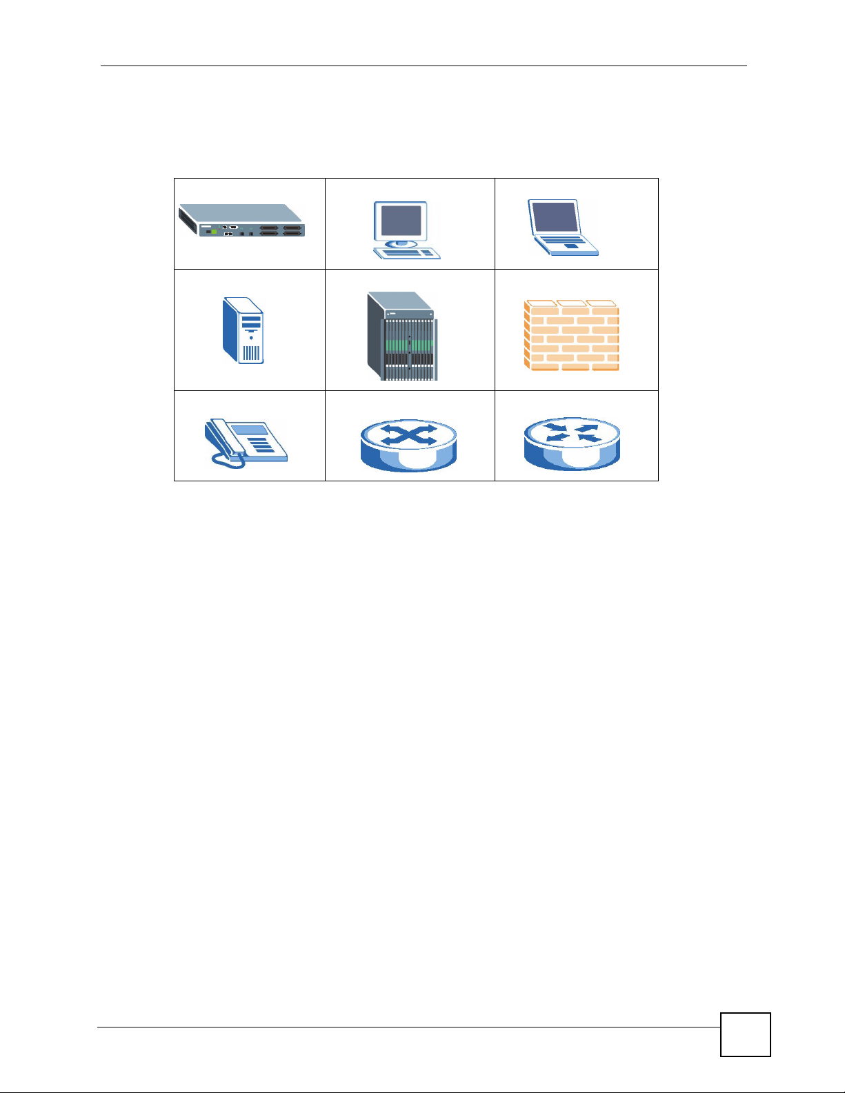
Icons Used in Figures
Figures in this User’s Guide may use the following generic icons. The IES-612-51A icon is
not an exact representation of your IES-612-51A.
IES-612-51A Computer Notebook computer
Server DSLAM Firewall
Telephone Switch Router
IES-612-51A User’s Guide
5

Safety Warnings
Safety Warnings
1 For your safety, be sure to read and follow all warning notices and instructions.
• Do NOT use this product near water, for example, in a wet basement or near a swimming
pool.
• Do NOT expose your device to dampness, dust or corrosive liquids.
• Do NOT store things on the device.
• Do NOT install, use, or service this device during a thunderstorm. There is a remote risk
of electric shock from lightning.
• Connect ONLY suitable accessories to the device.
• ONLY qualified service personnel should service or disassemble this device.
• Make sure to connect the cables to the correct ports.
• Place connecting cables carefully so that no one will step on them or stumble over them.
• Always disconnect all cables from this device before servicing or disassembling.
• Use ONLY an appropria t e power adaptor or cord for your device. Connect it to the right
supply voltage (for example, 110V AC in North America or 230V AC in Europe).
• Do NOT allow anything to rest on the power adaptor or cord and do NOT place the
product where anyone can walk on the power adaptor or cord.
• Do NOT use the device if the power adaptor or cord is damaged as it might cause
electrocution.
• If the power adaptor or cord is damaged, remove it from the device and the power source.
• Do NOT attempt to repair the power adaptor or cord. Contact your local vendor to order a
new one.
• Do not use the device outside, and make sure all the connections are indoors. There is a
remote risk of electric shock from lightning.
• Do NOT obstruct the device ventilation slots, as insufficient airflow may harm your
device.
• Use only No. 26 AWG (American Wire Gauge) or larger telecommunication line cord.
• Fuse Warning! Replace a fuse only with a fuse of the same type and rating.
• Warning! To avoid risk of electric shock, remove only one card at a time and do not place
fingers or objects inside the chassis. Cover empty slots with slot covers.
• The length of exposed (bare) power wire should not exceed 7 mm.
• Fan Module Warning! Use the fan module handle when pulling out or pushing in the fan
module. Be careful not to put fingers or objects inside the fan module.
6
This product is recyclable. Dispose of it properly.
IES-612-51A User’s Guide

Safety Warnings
IES-612-51A User’s Guide
7

Safety Warnings
8
IES-612-51A User’s Guide

Contents Overview
Contents Overview
Introduction ............................................................................................................................39
Getting to Know the IES-612-51A ............................................................................................. 41
Hardware Installation .......................................... .......................................................... .............45
Front Panel ................................................................................................................................ 49
Basic Settings ........................................................................................................................59
Introducing the Web Configurator .............................................................................................. 61
Initial Configuration ....................................................................................................................69
Home and Port Statistics Screens .............................................................................................75
System Information ......... .... ... .......................................................... ... ... .... ... ... ... .... ... ... .............87
General Setup ............................................. .... ... ... ... .... ... ... ... .... ................................................ 91
User Account ............ ... ... .... .......................................................... ... ... ... .... ... ............................. 93
Switch Setup ............. ... ... .... ... .......................................................... ... ... .... ... ... ..........................97
IP Setup ....................................... .... ... ... ... ... .... ... ..................................................................... 103
ENET Port Setup ..................................................................................................................... 105
xDSL Port Setup ......................................................................................................................107
xDSL Profiles Setup ................................................................................................................125
xDSL Line Data .......................................................................................................................137
Advanced Application .........................................................................................................143
VLAN ....................................................................................................................................... 145
IGMP ....................................................................................................................................... 153
Static Multicast .........................................................................................................................163
Multicast VLAN ........................................................................................................................ 165
Filtering ..................................... .................................................... ........................................... 171
MAC Filter ................................................................................................................................ 173
Spanning Tree Protocol ...................................... ... ... .... ... ... ..................................................... 175
Port Authentication ................... ... .... ... .......................................................... ... ... .... ... ... ... ........181
Port Security .......... ... ... ... .... .......................................................... ... ... ... .... ... ...........................185
DHCP Relay ............................................................................................................................ 187
DHCP Snoop ........................................................................................................................... 191
RFC 2684 Routed Mode .......................................................................................................... 195
PPPoA to PPPoE .................................................................................................................... 203
DSCP .............................. .................... ................... .................... ................... ........................... 209
TLS PVC ................... ... .......................................................... .... ... ... ... ... ...................................211
ACL ..................................... ................... ................... .................... ................... ........................ 215
Downstream Broadcast ...........................................................................................................221
IES-612-51A User’s Guide
9

Contents Overview
Syslog ....................................... .................................................... ........................................... 223
Access Control ........................................................................................................................225
Routing Protocol, Alarm and Management .......................................................................233
Static Routing .......................................................................................................................... 235
Maintenance ............................................................................................................................237
Diagnostic .................................... ....................................................... ..................................... 241
MAC Table ............................................................................................................................... 245
ARP Table ........................................ ... ... ... ... .... ... .....................................................................247
Alarm ....................................................................................................................................... 249
CLI Commands .....................................................................................................................255
Commands Summary ...................................................................................................... ... .... . 257
Command Examples ...............................................................................................................277
Alarm Commands ....................................................................................................................283
DHCP Commands ................................................................................................................... 291
IEEE 802.1Q Tagged VLAN Commands .................................................................................299
MAC Commands ..................................................................................................................... 307
IGMP Commands .................................................................................................................... 313
Packet Filter Commands .........................................................................................................327
IP Commands ........................................... ... .... ... ... ... .... ... ... ... .................................................. 331
Firmware and Configuration File Maintenance Commands ....................................................335
SNMP Commands ...................................................................................................................341
ADSL Commands ....................................................................................................................343
Virtual Channel Management Commands ...............................................................................375
ACL Commands ...................................................................................................................... 399
Troubleshooting and Specifications ..................................................................................405
Troubleshooting ..................................................... .................................................................. 407
Product Specifications ............................................................................................................. 417
Appendices and Index .........................................................................................................427
10
IES-612-51A User’s Guide

Table of Contents
Table of Contents
About This User's Guide..........................................................................................................3
Document Conventions............................................................................................................4
Safety Warnings ........................................................................................................................6
Contents Overview ...................................................................................................................9
Table of Contents....................................................................................................................11
List of Figures.........................................................................................................................27
List of Tables...........................................................................................................................35
Part I: Introduction................................................................................. 39
Chapter 1
Getting to Know the IES-612-51A..........................................................................................41
1.1 Overview ............. .......................................................... ... .... ... ... ... ....................................... 41
1.2 Applications .............. .... ... ... ... .... ... ... ... .......................................................... .... ... ... .............41
1.2.1 MTU Application ......................................................................................................... 41
1.2.2 Curbside Application .................................................................................................. 42
1.3 Ways to Manage the IES-612-51A ..... ... .... ... ... ... .... ............................................................. 43
1.4 Good Habits for Managing the IES-612-51A ....................................................................... 43
Chapter 2
Hardware Installation..............................................................................................................45
2.1 General Installation Instructions ......... .............................................................. ... ... .............45
2.2 Installation Scenarios ............................................. ... ... ... .... ... ... ... ... .... ... ... .......................... 45
2.2.1 Desktop Installation Procedure ..................................................................................45
2.2.2 Rack-Mounted Installation ..........................................................................................46
Chapter 3
Front Panel..............................................................................................................................49
3.1 Front Panel ............ ... .... ... .......................................................... ... ... .... ... ... ..........................49
3.1.1 Front Panel Ports ............................. .......................................................... ... ... ... .... ... 49
3.2 LEDs ............................................................................................. ... .... ................................49
3.2.1 Console Port ......................................................... .... ... ... ... ... .... ... ... ... .......................50
3.2.2 LAN Port (Ethernet) Connection ............................................ .... ... ... ... .... ... ................51
IES-612-51A User’s Guide
11

Table of Contents
3.2.3 Notes About MDFs (Main Distribution Frames) ......................................................... 51
3.2.4 Telco-50 Cables .................. ... ... .......................................................... .... ... ... ... ..........51
3.2.5 Telco-50 Connections ....................................... ... ... .... ... ... ... ....................................... 52
3.2.6 ADSL Connections ........................................................ ... ... ... .... ... ... ... .... ... ... .............52
3.2.7 Typical MDF Scenarios .............................................................................................. 53
Part II: Basic Settings............................................................................ 59
Chapter 4
Introducing the Web Configurator ........................................................................................61
4.1 Web Configurator Overview .................................................................................................61
4.2 Screen Privilege Levels ...... ... .... ... .......................................................... ... ... .... ... ... ... ... ....... 61
4.3 Accessing the Web Configurator .........................................................................................61
4.4 Navigation Panel ................................................................................................................. 63
4.5 Changing Your Password ............................................................. ... .... ................................ 65
4.6 Saving Your Configuration ...................................................................................................66
4.7 Logging Out of the Web Configurator ..................................... ............................................. 66
Chapter 5
Initial Configuration................................................................................................................69
5.1 Initial Configuration Overview .......................... .......................................................... ... .... ... 69
5.2 Initial Configuration .................................... ... ... ... .... ... .......................................................... 69
Chapter 6
Home and Port Statistics Screens.........................................................................................75
6.1 Home Screen ................ .......................................................... ... ... ... .... ... ............................. 75
6.1.1 Ethernet Port Statistics Screen ..................... ... ... ... .... ... ... ... ... .... ... ... ... .... ...................76
6.1.2 DSL Port Statistics Screen ............................................ ... ... ....................................... 79
6.1.3 RMON Statistics Screen .............................................................................................81
6.1.4 RMON History Screen ................................................................................................ 83
6.1.5 RMON History Detail Screen ..................................................................................... 84
Chapter 7
System Information ................................................................................................................87
Chapter 8
General Setup..........................................................................................................................91
Chapter 9
User Account...........................................................................................................................93
12
9.1 User Account Screen ................. ... ... ... ... .... ............................................................. ... ... ....... 93
9.2 Authentication Screen ........................................ .... ... ... ... .... ... ... ... ... .................................... 94
IES-612-51A User’s Guide

Table of Contents
Chapter 10
Switch Setup ...........................................................................................................................97
10.1 GARP Timer Setup ............................................................................................................97
10.2 Switch Modes .................................................................................................................... 97
10.2.1 Standalone Switch Mode .......................................................................................... 97
10.2.2 Port Isolation with Standalone Switch Mode Example ...... ... .... ... ... ... .... ... ... ... ... .... ... 98
10.2.3 Daisychain Switch Mode .......................................................................................... 98
10.2.4 Port Isolation with Daisychain Switch Mode Example .............................................. 98
10.3 Switch Setup Screen ......................................................................................................... 99
Chapter 11
IP Setup..................................................................................................................................103
Chapter 12
ENET Port Setup...................................................................................................................105
Chapter 13
xDSL Port Setup....................................................................................................................107
13.1 ADSL Standards Overview ..............................................................................................107
13.2 Downstream and Upstream .............................................................................................107
13.3 Profiles ............................................................................................................................. 107
13.4 Interleave Delay ............................................................................................................... 108
13.4.1 Fast Mode ..............................................................................................................108
13.5 Configured Versus Actual Rate ....................................................................................... 108
13.6 Default Settings ............................................................................................................... 109
13.7 xDSL Port Setup Screen .................................................................................................109
13.7.1 xDSL Port Setting Screen .......................................................................................111
13.8 Virtual Channels ...............................................................................................................115
13.8.1 Super Channel ........................................................................................................115
13.8.2 LLC ..........................................................................................................................116
13.8.3 VC Mux ...................................................................................................................116
13.8.4 Virtual Channel Profile ............................................................................................116
13.9 VC Setup Screen ..............................................................................................................116
13.10 Priority-based PVCs ......................................................................................................120
13.11 PPVC Setup Screen ...................................................................................................... 121
13.11.1 PPVC Setup Members Screen ............................................................................. 122
Chapter 14
xDSL Profiles Setup..............................................................................................................125
14.1 Port Profile Screen ..........................................................................................................125
14.2 ATM QoS .........................................................................................................................127
14.3 Traffic Shaping .................................................................................................................128
14.3.1 ATM Traffic Classes ............................................................................................... 128
14.3.2 Traffic Parameters ..................................................................................................128
IES-612-51A User’s Guide
13

Table of Contents
14.4 Upstream Policing ...........................................................................................................130
14.5 VC Profile Screen ............................................................................................................131
14.6 Alarm Profile Screen ........................................................................................................ 133
14.7 IGMP Filtering .................................................................................................................. 134
14.8 IGMP Filter Profile Screen .......................... ....................................................... ..............135
Chapter 15
xDSL Line Data......................................................................................................................137
15.1 xDSL Line Rate Info Screen ............................................................................................137
15.2 xDSL Performance Screen ..............................................................................................138
15.3 xDSL Line Data Screen ................................................................................................... 140
Part III: Advanced Application............................................................ 143
Chapter 16
VLAN......................................................................................................................................145
16.1 Introduction to VLANs ...................................................................................................... 145
16.2 Introduction to IEEE 802.1Q Tagged VLAN ..................................................................... 145
16.2.1 Forwarding Tagged and Untagged Frames .................................... ... .... ... ... ... ... .... . 146
16.3 VLAN Status Screen ........................................................................................................146
16.4 Static VLAN Setting Screen ........................................................ ..................................... 148
16.5 VLAN Port Setting Screen ............. ... ... .... ... ... ............................................................. .... . 149
Chapter 17
IGMP.......................................................................................................................................153
17.1 IGMP ............................................................................................................................... 153
17.2 IP Multicast Addresses ....................................................................................................153
17.2.1 IGMP Snooping ...................................................................................................... 153
17.2.2 IGMP Proxy ............................................................................................................153
17.3 IGMP Status Screen ........................................................................................................154
17.4 IGMP Bandwidth Screen ................................................................................................. 156
17.4.1 Bandwidth Port Setup Screen ................................................................................ 157
17.5 IGMP Setup Screen .........................................................................................................158
17.6 IGMP Filter Setup Screen .............................. ....................... ...................... ..................... 159
17.7 IGMP Count Screen ........................................................................................................159
17.8 IGMP Port Info Screen ....................................................................................................160
17.9 IGMP Port Group Screen ................................................................................................160
Chapter 18
Static Multicast......................................................................................................................163
18.1 Static Multicast .................................................................................................................163
14
IES-612-51A User’s Guide

Table of Contents
18.2 Static Multicast Screen ....................................................................................................163
Chapter 19
Multicast VLAN......................................................................................................................165
19.1 Multicast VLAN Overview ................................................................................................ 165
19.2 MVLAN Status Screen ..................................................................................................... 165
19.3 MVLAN Setup Screen .....................................................................................................166
19.4 MVLAN Group Screen .....................................................................................................168
Chapter 20
Filtering..................................................................................................................................171
20.1 Packet Filter Screen ........................................................................................................171
Chapter 21
MAC Filter..............................................................................................................................173
21.1 MAC Filter Introduction ....................................................................................................173
21.2 MAC Filter Screen ...........................................................................................................173
Chapter 22
Spanning Tree Protocol........................................................................................................175
22.1 RSTP and STP ................................................................................................................ 175
22.2 Spanning Tree Protocol S tatus Screen ............................................................................ 177
22.3 Spanning Tree Protocol Screen ....................................................................................... 178
Chapter 23
Port Authentication...............................................................................................................181
23.1 Introduction to Authentication .......................................................................................... 181
23.1.1 RADIUS ..................................................................................................................181
23.1.2 Introduction to Local User Database ...................................................................... 181
23.2 RADIUS Screen ............................................................................................................... 182
23.3 802.1x Screen .................................................................................................................183
Chapter 24
Port Security..........................................................................................................................185
24.1 Port Security Overview ....................................................................................................185
24.2 Port Security Screen ................................ ...................... ....................... ...................... ..... 185
Chapter 25
DHCP Relay...........................................................................................................................187
25.1 DHCP Relay .................................................................................................................... 187
25.2 DHCP Relay Agent Information Option (Option 82) ........................................................ 187
25.2.1 DHCP Relay Agent Circuit ID and Remote ID Sub-option Formats .......................187
25.3 DHCP Relay Screen ......................................... .... ... ... ... .... ... ... ... ... .... ... ...........................188
IES-612-51A User’s Guide
15

Table of Contents
Chapter 26
DHCP Snoop..........................................................................................................................191
26.1 DHCP Snoop Overview ...................................................................................................191
26.2 DHCP Snoop Screen ....................................................................................................... 191
26.3 DHCP Snoop Status Screen ............................................................................................192
26.4 DHCP Counter Screen .................................................................................................... 193
Chapter 27
RFC 2684 Routed Mode........................................................................................................195
27.1 RFC 2684 Routed Mode .................................................................................................. 195
27.1.1 RFC 2684 Routed Mode Example ......................................................................... 195
27.2 2684 Routed PVC Screen ............................................................................................... 196
27.3 2684 Routed Domain Screen ..........................................................................................198
27.4 RPVC Arp Proxy Screen ................................................................................................. 199
27.5 2684 Routed Gateway Screen ........................................................................................200
Chapter 28
PPPoA to PPPoE...................................................................................................................203
28.1 PPPoA to PPPoE Overview ............................................................................................ 2 03
28.2 PPPoA to PPPoE Screen ................................................................................................ 203
28.3 PPPoA to PPPoE Status Screen .....................................................................................206
Chapter 29
DSCP......................................................................................................................................209
29.1 DSCP Overview ............................................................................................................... 209
29.2 DSCP Setup Screen ........................................................................................................209
29.3 DSCP Map Screen .......................................................................................................... 210
Chapter 30
TLS PVC .................................................................................................................................211
30.1 Transparent LAN Service (TLS) Overview .......................................................................211
30.1.1 TLS Network Example ............................................................................................211
30.2 TLS PVC Screen .............................................................................................................212
Chapter 31
ACL.........................................................................................................................................215
31.1 Access Control Logic (ACL) Overview ............................................................................ 215
31.1.1 ACL Profile Rules ...................................................................................................215
31.1.2 ACL Profile Actions ................................................................................................ 216
31.2 ACL Setup Screen ...........................................................................................................216
31.3 ACL Profile Setup Screen ................................................................................................ 218
31.4 ACL Profile Map Screen ..................................................................................................219
16
IES-612-51A User’s Guide

Table of Contents
Chapter 32
Downstream Broadcast........................................................................................................221
32.1 Downstream Broadcast ................................................................................................... 221
32.2 Downstream Broadcast Screen .......................................................................................221
Chapter 33
Syslog....................................................................................................................................223
33.1 Syslog .............................................................................................................................. 223
33.2 SysLog Screen ................................................................................................................ 223
Chapter 34
Access Control......................................................................................................................225
34.1 Access Control Screen ............ ... ... ... ... .... ............................................................. ... ... .....225
34.2 Access Control Overview ................................................................................................ 225
34.3 SNMP .............................................................................................................................. 225
34.3.1 Supported MIBs ..................................................................................................... 227
34.3.2 SNMP Traps ........................................................................................................... 227
34.4 SNMP Screen ..................................................................................................................228
34.5 Service Access Control Screen ....................................................................................... 229
34.6 Remote Management Screen .......................................................................................... 230
Part IV: Routing Protocol, Alarm and Management.......................... 233
Chapter 35
Static Routing........................................................................................................................235
Chapter 36
Maintenance..........................................................................................................................237
36.1 Maintenance Screen ........................................................................................................237
36.2 Firmware Upgrade Screen ............................................ .... ... ... ... ... .... ... ... ... .... ... ... ...........237
36.3 Restore Configuration Screen ......................................................................................... 238
36.4 Backing Up a Configuration File ...................................................................................... 238
36.5 Load Factory Defaults .....................................................................................................239
36.6 Reboot System ................................................................................................................ 240
36.7 Command Line FTP ........................................................................................................ 240
Chapter 37
Diagnostic..............................................................................................................................241
37.1 Diagnostic Screen ...........................................................................................................241
Chapter 38
MAC Table..............................................................................................................................245
IES-612-51A User’s Guide
17

Table of Contents
38.1 Introduction to MAC Table ...............................................................................................245
38.2 MAC Table Screen ...........................................................................................................246
Chapter 39
ARP Table..............................................................................................................................247
39.1 Introduction to ARP Table ................................................................................................ 247
39.1.1 How ARP Works ......................................................... ... ... ... .... ... ... ........................ 247
39.2 ARP Table Screen ...........................................................................................................247
Chapter 40
Alarm......................................................................................................................................249
40.1 Alarm ............................................................................................................................... 249
40.2 Alarm Status Screen ................... ... ... ... .... ............................................................. ... ... ..... 249
40.3 Alarm Descriptions ..........................................................................................................250
40.4 Alarm Event Setup Screen .............................................................................................. 251
40.4.1 Edit Alarm Event Setup Screen ..............................................................................253
40.5 Alarm Port Setup Screen ................................................................................................. 254
Part V: CLI Commands........................................................................ 255
Chapter 41
Commands Summary...........................................................................................................257
41.1 Command Line Interface Overview ................................................................................. 257
41.2 Command Privilege Levels .............................................................................................. 257
41.3 Saving Your Configuration ...............................................................................................258
41.4 Commands ...................................................................................................................... 258
Chapter 42
Command Examples.............................................................................................................277
42.1 Command Examples Overview ....................................................................................... 277
42.2 Sys Commands ...............................................................................................................277
42.2.1 Log Show Command ..............................................................................................277
42.3 Log Format ...................................................................................................................... 277
42.3.1 Log Messages ........................................................................................................ 278
42.3.2 Log Clear Command .............................................................................................. 280
42.3.3 Info Show Command ..............................................................................................280
42.4 Isolation Commands ........................................................................................................280
42.4.1 Isolation Show Command ...................................................................................... 280
42.4.2 Isolation Enable Command ............................ ........................................................ 281
42.4.3 Isolation Disable Command ...................................................................................281
42.5 Statistics Monitor Command ............................................................................................ 281
18
IES-612-51A User’s Guide

Table of Contents
42.6 Statistics Port Command ............ ... ... ...............................................................................281
Chapter 43
Alarm Commands.................................................................................................................283
43.1 Alarm Commands ............................................................................................................283
43.2 General Alarm Command Parameters ............................................................................283
43.3 Alarm Show Command .................................................................................................... 283
43.4 Alarm Port Show Command ............................................................................................ 284
43.5 Alarm Port Set Command ................................................................................................ 285
43.6 Alarm Tablelist Command ................................................................................................ 285
43.7 Log Format ...................................................................................................................... 286
43.8 Alarm History Show Command ....................................................................................... 287
43.9 Alarm History Clear Command ........................................................................................ 287
43.10 Alarm XEdit Command .................................................................................................. 288
43.11 Alarm Cutoff Command .................. ... .... ........................................................................288
43.12 Alarm Clear Command .................................................................................................. 289
Chapter 44
DHCP Commands.................................................................................................................291
44.1 DHCP Relay Commands .................................................................................................291
44.1.1 Show Command .....................................................................................................291
44.1.2 Enable Command .................................................................................................. 291
44.1.3 Disable Command ..................................................................................................292
44.1.4 Server Set Command ........................... .......... .......... ......... ....... ......... .......... .......... . 292
44.1.5 Server Delete Command ........................................................................................292
44.1.6 Server Active Command ........................................................................................ 292
44.1.7 Relaymode Command ........................................................................................... 293
44.2 DHCP Relay Option 82 (Agent Information) Sub-option 1 (Circuit ID) ............................293
44.2.1 Option 82 Sub-option 1 Enable Command ................................................. ... ... .... . 293
44.2.2 Option 82 Sub-option 1 Disable Command .................... ... ... .... ... ... ... .... ... ... ... ... .....294
44.2.3 Option 82 Sub-option 1 Set Command .......................... ... ..................................... 2 94
44.3 DHCP Relay Option 82 (Agent Information) Sub-option 2 (Remote ID) .......................... 294
44.3.1 Option 82 Sub-option 2 Enable Command ................................................. ... ... .... . 294
44.3.2 Option 82 Sub-option 2 Disable Command .................... ... ... .... ... ... ... .... ... ... ... ... .....294
44.3.3 Option 82 Sub-option 2 Set Command .......................... ... ..................................... 2 94
44.4 DHCP Snoop Commands ................................................................................................ 295
44.4.1 DHCP Snoop Enable Command ............................................................................ 295
44.4.2 DHCP Snoop Disable Command ...........................................................................295
44.4.3 DHCP Snoop Flush Command .............................................................................. 296
44.4.4 DHCP Snoop Show Command ..............................................................................296
44.4.5 DHCP Counter Statistics Command ......................................................................296
44.4.6 DHCP Snoop Statistics Command .........................................................................297
IES-612-51A User’s Guide
19

Table of Contents
Chapter 45
IEEE 802.1Q Tagged VLAN Commands..............................................................................299
45.1 Introduction to VLANs ...................................................................................................... 299
45.2 IEEE 802.1Q Tagging Types ...........................................................................................299
45.3 Filtering Databases .......................................................................................................... 299
45.3.1 Static Entries (SVLAN Table) ................................................................................. 299
45.4 IEEE VLAN1Q Tagged VLAN Configuration Commands ................................................ 300
45.4.1 VLAN Port Show Command ...................................................................................300
45.4.2 VLAN PVID Command ... ........................................................................................ 300
45.4.3 VLAN Priority Command ........................................................................................ 300
45.4.4 VLAN Set Command .............................................................................................. 301
45.4.5 VLAN Frame Type Command ........................................................ ........................ 302
45.4.6 VLAN CPU Show Command .................................... ............ ............. ............. ........ 303
45.4.7 VLAN CPU Set Command ..................................................................................... 303
45.4.8 Configuring Management VLAN Example .................................................. ... ... .....304
45.4.9 VLAN Delete Command ......................................................................................... 304
45.5 VLAN Enable ................................................................................................................... 305
45.6 VLAN Disable .................................................................................................................. 305
45.6.1 VLAN Show Command ..........................................................................................305
Chapter 46
MAC Commands...................................................................................................................307
46.1 MAC Commands Overview .............................................................................................307
46.2 MAC Filter Commands .................................................................................................... 307
46.2.1 MAC Filter Show Command ...................................................................................307
46.2.2 MAC Filter Enable Command ................................................................................ 308
46.2.3 MAC Filter Disable Command ...............................................................................308
46.2.4 MAC Filter Mode Command ................... .... ... ... ... .... ... ... ........................................ 308
46.2.5 MAC Filter Set Command ...................................................................................... 309
46.2.6 MAC Filter Delete Command .................................................................................309
46.3 MAC Count Commands ................................................................................................... 310
46.3.1 MAC Count Show Command .................................................................................310
46.3.2 MAC Count Enable Command ............................. .......................................... ........ 310
46.3.3 MAC Count Disable Command .................. ... ... ... .... ... ... ... ......................................311
46.3.4 MAC Count Set Command ......................................................................................311
Chapter 47
IGMP Commands..................................................................................................................313
47.1 Multicast Overview ..........................................................................................................313
47.2 IGMP Snoop Commands ................................................................................................. 313
47.2.1 IGMP Snoop Show Command ...............................................................................313
47.2.2 IGMP Snoop Enable Command ............................................................................. 313
47.2.3 IGMP Snoop Disable Command ............................................................................314
20
IES-612-51A User’s Guide

Table of Contents
47.3 IGMP Filter Commands ................................................................................................... 314
47.3.1 IGMP Filter Show Command ................................................................................. 314
47.3.2 IGMP Filter Set Command ..................................................................................... 314
47.3.3 IGMP Filter Profile Set Command .......................................................................... 315
47.3.4 IGMP Filter Profile Delete Command ..................................................................... 315
47.3.5 IGMP Filter Profile Show Command ..................................................................... 316
47.4 IGMP Bandwidth Commands .......................................................................................... 316
47.4.1 IGMP Bandwidth Default Command ...................................................................... 316
47.4.2 IGMP Bandwidth Set Command ............................................................................ 317
47.4.3 IGMP Bandwidth Delete Command ....................................................................... 317
47.5 IGMP Bandwidth Port Commands ................................................................................... 317
47.5.1 IGMP Bandwidth Port Disable Command ..............................................................318
47.5.2 IGMP Bandwidth Port Enable Command ................................................. ... ... ... .... . 318
47.5.3 IGMP Bandwidth Port Set Command ..................................................................... 318
47.5.4 IGMP Bandwidth Port Show Command .................................................................318
47.6 IGMP Count Limit Commands .........................................................................................319
47.6.1 IGMP Count Disable Command ..................... ............................................. ........... 319
47.6.2 IGMP Count Enable Command ............................ ............. ............. ............. ........... 320
47.6.3 IGMP Count Set Command ................................................................................... 320
47.6.4 IGMP Count Show Command ................................................................................ 320
47.7 IGMP Snoop Statistics Commands ................................................................................. 321
47.7.1 IGMP Snoop Info Statistics Command ................................................................... 321
47.7.2 IGMP Group Statistics Command ..........................................................................321
47.7.3 IGMP Port Info Statistics Command .................................................. .... ... ... ... ... .... . 322
47.7.4 IGMP Port Group Statistics Command ................................................................... 322
47.8 Multicast VLAN Commands ............................................................................................. 323
47.8.1 Multicast VLAN Set Command .......................... ............. ............. ............. ............. . 323
47.8.2 Multicast VLAN Delete Command ..........................................................................324
47.8.3 Multicast VLAN Disable Command ........................................................................324
47.8.4 Multicast VLAN Enable Command ......................................................................... 324
47.8.5 Multicast VLAN Show Command ........................................................................... 324
47.8.6 Multicast VLAN Group Set Command ....................................................................325
47.8.7 Multicast VLAN Group Delete Command ............................. ................. ................ . 325
47.8.8 Multicast VLAN Group Show Command ................................................................ 326
Chapter 48
Packet Filter Commands......................................................................................................327
48.1 Packet Filter Commands ................................................................................................. 327
48.1.1 Packet Filter Show Command ........................ ............. ............. ............. ............ ..... 327
48.1.2 Packet Filter Set Command ................................................................................... 328
48.1.3 Packet Filter PPPoE Only Command .....................................................................329
Chapter 49
IP Commands........................................................................................................................331
IES-612-51A User’s Guide
21

Table of Contents
49.1 IP Commands Introduction ..............................................................................................331
49.2 IP Settings and Default Gateway ..................................................................................... 331
49.3 General IP Commands ....................................................................................................332
49.3.1 Show ...................................................................................................................... 332
49.3.2 Ping Command ...................................................................................................... 332
49.3.3 Route Set Command ..............................................................................................332
49.3.4 Route Delete Command .........................................................................................333
49.3.5 Route Show Command ..........................................................................................333
49.3.6 ARP Show Command ............................................................................................334
49.3.7 ARP Flush Command ............................................................................................ 334
49.4 Statistics IP Command ..................... ... .... ........................................................................334
Chapter 50
Firmware and Configuration File Maintenance Commands .............................................335
50.1 Firmware and Configuration File Maintenance Overview ................................................ 335
50.2 Filename Conventions .....................................................................................................335
50.3 Editable Configuration File .............................................................................................. 336
50.3.1 Editable Configuration File Backup ............... ... ... .... ... ... ........................................ 336
50.3.2 Edit Configuration File ........................................................................................... 337
50.3.3 Editable Configuration File Upload .................... ... .... ... ... ... ... .... .............................. 338
50.4 Firmware File Upgrade ...................................................................................................339
Chapter 51
SNMP Commands.................................................................................................................341
51.1 SNMP Commands ...........................................................................................................341
51.1.1 Get Community Command .....................................................................................341
51.1.2 Set Community Command .....................................................................................341
51.1.3 Trusted Host Set Command ...................................................................................341
51.1.4 Trap Community Command ...................................................................................342
51.1.5 Trap Destination Set Command ............................................... .............................. 342
51.1.6 Show SNMP Settings Command ...........................................................................342
Chapter 52
ADSL Commands..................................................................................................................343
52.1 DSL Port Commands ....................................................................................................... 343
52.1.1 DSL Port Show Command .....................................................................................343
52.1.2 DSL Port Enable Command ................................................................................... 343
52.1.3 DSL Port Disable Command ..................................................................................344
52.1.4 DSL Port Profile Show Command ........................................ .... ... ... ........................ 344
52.1.5 DSL Port Profile Set Command ............................................................................. 345
52.1.6 DSL Port Profile Delete Command ............................................. ........................... 347
52.1.7 DSL Port Profile Map Command ............................................................................ 347
52.1.8 DSL Port Name Command .................................................................................... 348
22
IES-612-51A User’s Guide

Table of Contents
52.1.9 DSL Port Tel Command ......................................................................................... 348
52.1.10 DSL Port Loopback Command ............................................................................ 349
52.1.11 DSL Port Upstream PSD Command ......................... ... ... ... .... ... ... ... .... ... ... ... ... .... . 349
52.1.12 DSL Port Downstream PSD Command ............................................................... 350
52.1.13 DSL Port Upstream Carrier Command ................................................................350
52.1.14 DSL Port Downstream Carrier0 Command ..........................................................351
52.1.15 DSL Port Downstream Carrier1 Command ..........................................................352
52.1.16 PMM Parameters Command ................................................................................353
52.1.17 Impulse Noise Protection Command .................................................................... 355
52.1.18 Annex L Enable Command .................................................................................. 355
52.1.19 Annex L Disable Command ................................................................................. 355
52.1.20 Annex M Enable Command ................................................................................. 356
52.1.21 Annex M Disable Command ................................................................................ 356
52.1.22 Annex I Enable Command ................................................................................... 356
52.1.23 Annex I Disable Command .................................................................................. 357
52.2 DSL Port Statistics Commands ....................................................................................... 357
52.2.1 DSL Port Show Command .....................................................................................357
52.2.2 Linedata Command ................................................................................................ 358
52.2.3 Lineinfo Command .................................. ............................................................... 359
52.2.4 Lineperf Command .................................................................................................360
52.2.5 15 Minute Performance Command ........................................................................ 361
52.2.6 1 Day Performance Command .......................... ............. ............. ............. ............. . 362
52.2.7 Line Diagnostics Set Command ............................................................................. 363
52.2.8 Line Diagnostics Get Command ............................................................................ 363
52.2.9 Line Diagnostics Get 992.3 Command ............................................. .....................365
52.2.10 SELT Diagnostic Set Command ...........................................................................367
52.2.11 SELT Diagnostic Get Command ........................................................................... 368
52.2.12 Tone Diagnostics 992.3 Command .... ... .......................................................... .... . 368
52.3 Alarm Profile Commands ................................................................................................. 370
52.3.1 Alarm Profile Show Command ............................................................................... 370
52.3.2 Alarm Profile Set Command ...................................................................................371
52.3.3 Alarm Profile Delete Command ................................ ............ ............. ............. ........ 372
52.3.4 Alarm Profile Map Command .................................................................................372
52.3.5 Alarm Profile Showmap Command ........................................................................ 373
Chapter 53
Virtual Channel Management Commands..........................................................................375
53.1 Virtual Channel Management Overview .......................................................................... 375
53.2 Virtual Channel Profile Commands ....................................... ...... ... ....... ...... ....... ...... ....... . 375
53.2.1 Show Virtual Channel Profile Command ................................................................ 375
53.2.2 Set Virtual Channel Profile Command ..................................................................375
53.2.3 Delete Virtual Channel Profile Command ............................................................. 377
53.3 PVC Channels ................................................................................................................. 377
IES-612-51A User’s Guide
23

Table of Contents
53.3.1 PVC Show Command ............................................................................................377
53.3.2 PVC Set Command ................................................................................................ 378
53.3.3 PVC Delete Command ........................................................................................... 379
53.4 Priority-based PVCs ........................................................................................................ 379
53.4.1 PPVC Set Command ............................................................................................. 379
53.4.2 PPVC Member Set Command ............................................................................... 380
53.5 PPVC Member Delete Command .................................................................................... 381
53.6 PPVC Member Show Command .....................................................................................382
53.6.1 PPVC Show Command .......................................................................................... 382
53.6.2 PPVC Delete Command ........................................................................................ 383
53.7 2684 Routed Mode Commands .......................................................................................383
53.7.1 2684 Routed Mode Example ............................. ............. ............. ............. ............. . 384
53.7.2 RPVC Gateway Set Command ..............................................................................385
53.7.3 RPVC Gateway Show Command .......................................................................... 385
53.7.4 RPVC Gateway Delete Command .........................................................................386
53.7.5 RPVC Set Command .............................................................................................386
53.7.6 RPVC Show Command ..........................................................................................387
53.7.7 RPVC Delete Command ........................................................................................388
53.7.8 RPVC Route Set Command ...................................................................................388
53.7.9 RPVC Route Show Command ...............................................................................389
53.7.10 RPVC Route Delete Command ............................................................................390
53.7.11 RPVC ARP Agingtime Set Command .................................................................. 390
53.7.12 RPVC ARP Agingtime Show Command .............................................................. 391
53.7.13 RPVC ARP Show Command ............................................................................... 391
53.7.14 RPVC ARP Flush Command ............................................................................... 391
53.8 PPPoA to PPPoE (PAE) Commands ...............................................................................392
53.8.1 PAE PVC Delete Command ................................. .................................................. 392
53.8.2 PAE PVC Set Command ........................................................................................ 392
53.8.3 PAE PVC Show Command ....................................................................................393
53.8.4 PAE PVC Session Command ................................................................................ 394
53.8.5 PAE PVC Counter Command ................................................................................ 394
53.9 Transparent LAN Service (TLS) Commands ................................................................... 396
53.9.1 TLS PVC Delete Command ................................................................................... 396
53.9.2 TLS PVC Set Command ........................................................................................396
53.9.3 TLS PVC Show Command .....................................................................................397
Chapter 54
ACL Commands....................................................................................................................399
54.1 ACL Profile Commands ................................................................................................... 399
54.1.1 ACL Profile Set Command .....................................................................................399
54.1.2 ACL Profile Delete Command ..................... ........................................................... 401
54.1.3 ACL Profile Show Map Command ......................................................................... 401
54.1.4 ACL Profile Show Command ................................................................................. 401
24
IES-612-51A User’s Guide

Table of Contents
54.2 ACL Assignment Commands .......................................................................................... 402
54.2.1 ACL Assignment Set Command ............................................................................ 402
54.2.2 ACL Assignment Delete Command ....................................................................... 402
54.2.3 ACL Assignment Show Command ................. ............................................. ........... 403
Part VI: Troubleshooting and Specifications .................................... 405
Chapter 55
Troubleshooting....................................................................................................................407
55.1 The SYS LED Does Not Turn On ....................................................................................407
55.2 The ALM LED Is On ........................................................................................................ 407
55.3 LAN Port LEDs Do Not Turn On ......................................................................................408
55.4 LAN Port Data Transmission ........................................................................................... 408
55.5 DSL Data Transmission ................................................................................................... 408
55.6 There Is No Voice on a DSL Connection ......................................................................... 409
55.7 Testing Wiring .................................................................................................................. 409
55.8 Local Server .....................................................................................................................411
55.9 Data Rate .........................................................................................................................411
55.10 Configured Settings .......................................................................................................412
55.11 Password . .... .......................................................... ... ... .... ... ... ........................................ 412
55.12 System Lockout ............................................................................................................. 412
55.13 SNMP ............................................................................................................................ 412
55.14 Telnet ............................................................................................................................. 413
55.15 Resetting the Defaults ...................................................................................................413
55.15.1 Resetting the Defaults Via Command .................................................................. 413
55.15.2 Uploading the Default Configuration File .............................................................414
55.16 Recovering the Firmware ..............................................................................................415
Chapter 56
Product Specifications.........................................................................................................417
56.1 Device Specifications .......................................................................................................417
56.2 Firmware Features ..........................................................................................................418
56.3 Standards Supported .......................................................................................................422
56.4 Default Settings ............................................................................................................... 423
56.5 Hardware Telco-50 Connector Pin Assignments ............................................................. 425
56.6 Console Cable Pin Assignments .....................................................................................425
Part VII: Appendices and Index.......................................................... 427
Appendix A Legal Information ..............................................................................................429
IES-612-51A User’s Guide
25

Table of Contents
Appendix B Customer Support.............................................................................................433
Index.......................................................................................................................................439
26
IES-612-51A User’s Guide

List of Figures
List of Figures
Figure 1 MTU Application ...................................................................................................................... 42
Figure 2 Curbside Application ............................................................................................................... 42
Figure 3 Attaching Rubber Feet ............................................................................................................. 46
Figure 4 Attaching Mounting Brackets and Screws ................................................................................47
Figure 5 Rack Mounting .........................................................................................................................47
Figure 6 Front Panel: AC Input ..............................................................................................................49
Figure 7 MDF Wiring ..............................................................................................................................51
Figure 8 Telco-50 Cable with RJ-11 Connectors ....................................................................................52
Figure 9 Installation Overview ................................................................................................................53
Figure 10 Installation Scenario A ............................................................................................................ 54
Figure 11 One MDF for End-user and CO Connections ............................... .......................................... 55
Figure 12 Installation Scenario B ............................................................................................................ 56
Figure 13 Two Separate MDFs for End-user and CO Connections ....................... ... ... ... .... ... ... ... ... .... ... 57
Figure 14 Installation Scenario C ........................................................................................................... 58
Figure 15 Login ....................................................................................................................................... 62
Figure 16 Home ...................................................................................................................................... 62
Figure 17 User Account ...................................................... ... .... ... .......................................................... 65
Figure 18 User Account ...................................................... ... .... ... .......................................................... 66
Figure 19 Logout .................................................................................................................................... 67
Figure 20 IP Setup .................................................................................................................................. 69
Figure 21 xDSL Port Setup ..................................................................................................................... 70
Figure 22 VC Setup ................................................................................................................................ 71
Figure 23 VC Setup, Delete .................................................................................................................... 71
Figure 24 Select Ports ............................................................................................................................ 71
Figure 25 VC Setup ................................................................................................................................ 72
Figure 26 VC Setup ................................................................................................................................ 72
Figure 27 Select Ports ............................................................................................................................ 73
Figure 28 VC Setup ................................................................................................................................ 73
Figure 29 Config Save ............................................................................................................................ 73
Figure 30 Config Save, Save Successful ...............................................................................................74
Figure 31 Home ...................................................................................................................................... 75
Figure 32 Port Statistics (Ethernet) .................................................................. .................... ................... 77
Figure 33 Port Statistics (DSL) ................. .... ... ... ............................................................. .... ...................80
Figure 34 Port Statistics (RMON) ................. ... ... ... ... .... ... ... ....................................................................82
Figure 35 Port Statistics (RMON History)) ................ .... ... ... ... .... ... ... ... .................................................... 84
Figure 36 Port Statistics (RMON History Detail)) ...... .... ... ... ... .... ... ... ... .... ... ... ... ... .... ... ... ... .... ... ... .............85
Figure 37 System Info ............................................................................................................................ 87
Figure 38 General Setup .............................. ... ... ... ... .... ... ... ... ................................................................. 91
IES-612-51A User’s Guide
27

List of Figures
Figure 39 User Account ...................................................... ... .... ... .......................................................... 93
Figure 40 Authentication ......................................................................................................................... 94
Figure 41 Port Isolation with Standalone Switch Mode Example ........................................................... 98
Figure 42 Port Isolation with Daisychain Switch Mode Example ............................................................ 99
Figure 43 Switch Setup ...................................................... ... .... ... ... ... .................................................. 100
Figure 44 IP Setup ................................................................................................................................ 103
Figure 45 ENET Port Setup ..................................................................................................................105
Figure 46 xDSL Port Setup ................................................................................................................... 109
Figure 47 Select Ports ...........................................................................................................................110
Figure 48 xDSL Port Setting ..................................................................................................................112
Figure 49 VC Setup ...............................................................................................................................117
Figure 50 Basic Setting, xDSL Port Setup, VC Setup, Delete ...............................................................119
Figure 51 Select Ports ...........................................................................................................................119
Figure 52 Select Ports .......................................................................................................................... 120
Figure 53 PPVC Setup ......................................................................................................................... 121
Figure 54 PPVC Setup, Edit ................................................................................................................. 122
Figure 55 Port Profile ............................. ... .... ... ... ... ... .... ........................................................................125
Figure 56 PCR, SCR and MBS in Traffic Shaping ................................................................................ 129
Figure 57 TAT, CDVT and BT in Traffic Shaping ..................................................................................130
Figure 58 VC Profile ............................................................................................................................. 131
Figure 59 Alarm Profile .........................................................................................................................133
Figure 60 IGMP Filter Profile ................................................................................................................ 135
Figure 61 xDSL Line Rate Info .............................................................................................................137
Figure 62 xDSL Performance ............................................................................................................... 139
Figure 63 xDSL Line Data .................................................................................................................... 141
Figure 64 VLAN Status ......................................................................................................................... 147
Figure 65 Static VLAN Setting ..............................................................................................................148
Figure 66 VLAN Port Setting ................................................................................................................ 150
Figure 67 Select Ports .......................................................................................................................... 151
Figure 68 IGMP Proxy Network Example .............................................................................................154
Figure 69 IGMP (Status) ....................................................................................................................... 155
Figure 70 IGMP Bandwidth ..................................................................................................................156
Figure 71 Bandwidth Port Setup ........................................................................................................... 157
Figure 72 IGMP Setup .......................................................................................................................... 158
Figure 73 IGMP Count .......................................................................................................................... 159
Figure 74 IGMP Port Info ...................................................................................................................... 160
Figure 75 IGMP Port Group .................................................................................................................. 160
Figure 76 Static Multicast ..................................................................................................................... 163
Figure 77 MVLAN Status ......................................................................................................................165
Figure 78 MVLAN Setup ....................................................................................................................... 167
Figure 79 MVLAN Group ...................................................................................................................... 168
Figure 80 Packet Filter .........................................................................................................................171
Figure 81 MAC Filter ............................................................................................................................173
28
IES-612-51A User’s Guide

List of Figures
Figure 82 STP Root Ports and Designated Ports ................................................................................. 176
Figure 83 Spanning Tr ee Protoc ol Status .............................................................................................177
Figure 84 Spanning Tr ee Protoc ol ........................................................................................................179
Figure 85 RADIUS Server .................................................................................................................... 181
Figure 86 RADIUS ................................................................................................................................ 182
Figure 87 802.1x ................................................................................................................................... 183
Figure 88 Port Security .................................................... ... ... .... ... ........................................................ 185
Figure 89 Select Ports .......................................................................................................................... 186
Figure 90 DHCP Relay Agent Circuit ID Sub-option Format .................................. ... ... ... .... ... ... ... ... .... . 187
Figure 91 DHCP Relay Agent Remote ID Sub-option Format ..............................................................188
Figure 92 DHCP Relay ......................................................................................................................... 188
Figure 93 DHCP Snoop ........................................................................................................................191
Figure 94 DHCP Snoop Status ............................................................................................................. 192
Figure 95 DHCP Counter .....................................................................................................................193
Figure 96 RFC 2684 Routed Mode Example ....................................................................................... 196
Figure 97 RFC 2684 Routed PVC ........................................................................................................ 197
Figure 98 2684 Routed Domain ................................................................ ... ... ... .... ... ... ... .... ... ... ...........198
Figure 99 RPVC Arp Proxy ................................................................................................................... 200
Figure 100 2684 Routed Gateway ........................................................................................................201
Figure 101 Mixed PPPoA-to-PPPoE Broadband Network Example ................................................... 203
Figure 102 PPPoA to PPPoE ...............................................................................................................204
Figure 103 PPPoA to PPPoE Status ....................................................................................................206
Figure 104 DSCP Setup ....................................................................................................................... 209
Figure 105 DSCP Map .........................................................................................................................210
Figure 106 Transparent LAN Service Network Example ..................................................................... 212
Figure 107 TLS PVC ............................................................................................................................213
Figure 108 ACL Setup .......................................................................................................................... 217
Figure 109 ACL Profile Setup ...............................................................................................................218
Figure 110 ACL Profile Map .................................................................................................................220
Figure 111 Downstream Broadcast ....................................................................................................... 221
Figure 112 SysLog ................................................................................................................................ 223
Figure 113 Access Control ...................................................................................................................225
Figure 114 SNMP Management Model ................................................................................................ 226
Figure 115 SNMP ................................................................................................................................. 229
Figure 116 Service Access Control ......................................................................................................230
Figure 117 Remote Management (Secured Client Setup) ....................................................................231
Figure 118 Static Routing ..................................................................................................................... 235
Figure 119 Maintenance ....................................................................................................................... 237
Figure 120 Firmware Upgrade .............................................................................................................. 238
Figure 121 Restore Configuration ........................................................................................................ 238
Figure 122 Restore Default Configuration ............................................................................................239
Figure 123 Restore Factory Default Settings, Reboot .......................................................................... 240
Figure 124 Reboot System ...................................................................................................................240
IES-612-51A User’s Guide
29

List of Figures
Figure 125 Diagnostic ........................................................................................................................... 241
Figure 126 MAC Table Filtering Flowchart ...........................................................................................245
Figure 127 MAC Table .......................................................................................................................... 246
Figure 128 ARP Table .......................................................................................................................... 248
Figure 129 Alarm Status .......................................................................................................................249
Figure 130 Alarm Event Setup .............................................................................................................252
Figure 131 Alarm Event Setup Edit ...................................................................................................... 253
Figure 132 Alarm Port Setup ................................................................................................................ 254
Figure 133 Log Show Command Example ........................................................................................... 277
Figure 134 Info Show Example ............................................................................................................280
Figure 135 Isolation Show Example ..................................................................................................... 281
Figure 136 Statistics Monitor Command Example ................................................................................ 281
Figure 137 Statistics Port Command Example .....................................................................................282
Figure 138 Alarm Show Command Example .......................................................................................284
Figure 139 Alarm Port Show Command Example ................................................................................ 285
Figure 140 Alarm Port Set Command Example ................................................................................... 285
Figure 141 Alarm Tablelist Command Example ................................................................................... 286
Figure 142 Alarm History Show Command Example ................ ... ........................................................ 287
Figure 143 Alarm History Clear Command Example ............................................................................287
Figure 144 Alarm Xedit Command Example ........................................................................................ 288
Figure 145 Show Command Example .................................................................................................. 291
Figure 146 DHCP Snoop Enable Command Example .........................................................................295
Figure 147 DHCP Snoop Show Command Example ...........................................................................296
Figure 148 DHCP Counter Statistics Command Example .................................................................... 297
Figure 149 DHCP Snoop Statistics Command Example ...................................................................... 297
Figure 150 VLAN Port Show Command Example . ............................................................................... 300
Figure 151 VLAN PVID Command Example ........................................................................................ 300
Figure 152 VLAN CPU Set Command Example .................................................................................. 301
Figure 153 Modifying the Static VLAN Example ...................................................................................302
Figure 154 VLAN Frame Type Command Example .............................................................................303
Figure 155 VLAN CPU Set Command Example .................................................................................. 303
Figure 156 VLAN CPU Set Command Example .................................................................................. 303
Figure 157 CPU VLAN Configuration and Activation Example ............................................................ 304
Figure 158 Deleting Default VLAN Example ........................................................................................ 304
Figure 159 VLAN Delete Command Example ...................................................................................... 304
Figure 160 VLAN Show Command Example .......................................................................................305
Figure 161 MAC Filter Show Command Example ................................................................................ 307
Figure 162 MAC Filter Enable Command Example ..............................................................................308
Figure 163 MAC Filter Disable Command Example ........................................ ... .... ... ... ... .... ... ... ... ... .... . 308
Figure 164 MAC Filter Mode Command Example ................................................................................ 309
Figure 165 MAC Filter Set Command Example ................................................................................... 309
Figure 166 MAC Filter Delete Command Example .............................................................................. 309
Figure 167 MAC Count Show Command Example ..............................................................................310
30
IES-612-51A User’s Guide

List of Figures
Figure 168 MAC Count Enable Command Example ............................................................................310
Figure 169 MAC Count Disable Command Example ............................................................................311
Figure 170 MAC Count Set Command Example ...................................................................................311
Figure 171 IGMP Snoop Show Command Example ............................................................................ 313
Figure 172 IGMP Snoop Enable Command Example ..........................................................................313
Figure 173 IGMP Snoop Disable Command Example ......................................................................... 314
Figure 174 IGMP Filter Show Command Example ............................................................................... 314
Figure 175 IGMP Filter Set Command Example ..................................................................................315
Figure 176 IGMP Filter Profile Set Command Example ........ .... ... ... ... .... ... ... ... ... .... .............................. 315
Figure 177 IGMP Filter Profile Delete Command Example .................................................................. 316
Figure 178 IGMP Filter Show Command Example ............................................................................... 316
Figure 179 IGMP Bandwidth Port Show Command Example .............................................................. 319
Figure 180 IGMP Count Disable Command Example .......................................................................... 319
Figure 181 IGMP Count Enable Command Example ........................................................................... 320
Figure 182 IGMP Count Set Command Example ................................................................................. 320
Figure 183 IGMP Count Show Command Example .............................................................................321
Figure 184 IGMP Snoop Info Statistics Command Example ............................................................... 321
Figure 185 IGMP Group Statistics Command Example ...................................................................... 322
Figure 186 IGMP Port Info Statistics Command Example ...................................................................322
Figure 187 IGMP Port Group Statistics Command Example ...............................................................323
Figure 188 Multicast VLAN Disable Command Example .................................................................... 324
Figure 189 Multicast VLAN Show Command Example ..................... .... ... ... ... ... .... ... ... ... .... ... ... ... ... .... . 325
Figure 190 Multicast VLAN Group Set Command Example ................................................................ 325
Figure 191 Packet Filter Show Command Example ............................................................................. 327
Figure 192 Packet Filter Set Command Example ................................................................................ 329
Figure 193 Packet Filter PPPoE Only Command Example ................ .................................................. 329
Figure 194 IP Settings and Default Gateway Address Commands ...................................................... 331
Figure 195 IP Settings and Default Gateway Address Command Example ......................................... 332
Figure 196 Route Show Command Example .......................................................................................333
Figure 197 ARP Show Command Example ......................................................................................... 334
Figure 198 Statistics IP Command Example ........................................................................................ 334
Figure 199 FTP Put Configuration File Example ..................................................................................335
Figure 200 FTP Get Configuration File Example ..................................................................................336
Figure 201 Example: Use an FTP Client to Connect to the IES-612-51A ............................................337
Figure 202 Example: Enter the Management Password ........... ... ... ..................................................... 337
Figure 203 Example: Get the Configuration File config-0 ... ... .... ... ... ... .... ... ... ... ... .... ... ... ........................ 337
Figure 204 Example: Close FTP Client ................................................................................................337
Figure 205 Configuration File Example ................................................................................................ 338
Figure 206 Example: Use an FTP Client to Connect to the IES-612-51A ............................................338
Figure 207 Example: Enter the Management Password ........... ... ... ..................................................... 339
Figure 208 Example: Upload the Configuration File config-0 ...............................................................339
Figure 209 Example: Close FTP Client ................................................................................................339
Figure 210 Example: Use an FTP Client to Connect to the IES-612-51A ............................................339
IES-612-51A User’s Guide
31

List of Figures
Figure 211 Example: Enter the Management Password ...................................................................... 339
Figure 212 Example: Transfer the Firmware File .................................................................................339
Figure 213 Example: Close FTP Client ................................................................................................339
Figure 214 DSL Port Show Command Example ..................................................................................343
Figure 215 DSL Profile Show Command Example ............................................................................... 345
Figure 216 DSL Port Profile Set Command Example 1 ........................................................................346
Figure 217 DSL Port Profile Set Command Example 2 ........................................................................347
Figure 218 DSL Port Profile Delete Command Example ................................................................. .... . 347
Figure 219 DSL Port Profile Delete Command Example ................................................................. .... . 348
Figure 220 DSL Port Name Command Example ..................................................................................348
Figure 221 DSL Port Tel Command Example ....................................................................................... 349
Figure 222 DSL Port Loopback Command Example ............................................................................349
Figure 223 DSL Port Upstream PSD Command Example ................................................................... 350
Figure 224 DSL Port Downstream PSD Command Example ................. ......................... ..................... 350
Figure 225 DSL Port Upstream Carrier Command Example . .... ... ... ... .... ... ... ... ... .................................. 351
Figure 226 DSL Port Upstream Carrier Command Display Example .............................. .... ... ... ... ... .... . 351
Figure 227 DSL Port Downstream Carrier0 Command Example 1 ...................................................... 352
Figure 228 DSL Port Downstream Carrier0 Command Display Example ............................................352
Figure 229 DSL Port Downstream Carrier0 Command Example 2 ...................................................... 352
Figure 230 DSL Port Downstream Carrier1 Command Example 1 ...................................................... 353
Figure 231 DSL Port Downstream Carrier1 Command Example 2 ...................................................... 353
Figure 232 DSL Port Downstream Carrier1 Command Display Example ............................................353
Figure 233 PMM Parameters Command Example ............................................................................... 354
Figure 234 Impulse Noise Protection Command Example .............................. ..................................... 355
Figure 235 Annex L Enable Command Example ................................................................................ 355
Figure 236 Annex L Disable Command Example ................................................................................356
Figure 237 Annex M Enable Command Example ................................................................................ 356
Figure 238 Annex M Disable Command Example ................................................................................356
Figure 239 Annex I Enable Command Example .................................................................................. 357
Figure 240 Annex I Disable Command Example ..................................................................................357
Figure 241 DSL Port Show Command Example ..................................................................................357
Figure 242 Linedata Command Example .............................................................................................358
Figure 243 Lineinfo Command Example ..............................................................................................359
Figure 244 Lineperf Command Example .............................................................................................. 360
Figure 245 15 Minute Performance Command Example ..................................................................... 361
Figure 246 1Day Performance Command Example ............................................................................. 363
Figure 247 Line Diagnostics Set Command Example .......................................................................... 363
Figure 248 Line Diagnostics Get Command Example .......................................................................... 364
Figure 249 Line Diagnostics Get 992.3 Command Example .................................. ................... ........... 366
Figure 250 SELT Diagnostic Set Command Example .......................................................................... 367
Figure 251 Line Diagnostics Get Command Example .......................................................................... 368
Figure 252 Tone Diagnostics Command Example ...............................................................................369
Figure 253 Alarm Profile Show Command Example ............. .... ... ........................................................ 370
32
IES-612-51A User’s Guide

List of Figures
Figure 254 Alarm Profile Set Command Example ................................................................................ 372
Figure 255 Alarm Profile Delete Command Example ........................................................................... 372
Figure 256 Alarm Profile Map Command Example ..............................................................................373
Figure 257 Alarm Profile Showmap Command Example ..................................................................... 373
Figure 258 Set Virtual Channel Profile Command Example 1 .............................................................. 376
Figure 259 Set Virtual Channel Profile Command Example 2 .............................................................. 376
Figure 260 Set Virtual Channel Profile Command Example 3 .............................................................. 377
Figure 261 Delete Virtual Channel Profile Command Example ............................................................377
Figure 262 PVC Set Command Example .............................................................................................379
Figure 263 PPVC Set Command Example ......................... .................... ................... ................... ........ 380
Figure 264 PPVC Member Set Command Example ............................................................................ 381
Figure 265 PPVC Member Delete Command Example ............................................ ... ... .... ... ... ... ... .... . 382
Figure 266 PPVC Member Show Command Example ......................................................................... 382
Figure 267 PPVC Show Command Example ....................................................................................... 383
Figure 268 PPVC Delete Command Example ......................................................................................383
Figure 269 2684 Routed Mode Example .............................................................................................. 384
Figure 270 2684 Routed Mode Commands Example .......................................................................... 385
Figure 271 RPVC Gateway Set Command Example ...........................................................................385
Figure 272 RPVC Gateway Show Command Example ........................................................................386
Figure 273 RPVC Gateway Delete Command Example ......................................................................386
Figure 274 RPVC Set Command Example .......................................................................................... 387
Figure 275 RPVC Show Command Example ....................................................................................... 388
Figure 276 RPVC Delete Command Example ..................................................................................... 388
Figure 277 RPVC Route Set Command Example ................................................................................ 389
Figure 278 RPVC Route Show Command Example ............................................................................ 390
Figure 279 RPVC Route Delete Command Example ........................................................................... 390
Figure 280 RPVC ARP Agingtime Command Example ....................................................................... 391
Figure 281 RPVC ARP Agingtime Show Command Example ............................................................. 391
Figure 282 RPVC ARP Agingtime Show Command Example ............................................................. 391
Figure 283 PAE PVC Set Command Example .................................................................................... 393
Figure 284 PAE PVC Show Command Example ................................................................................ 394
Figure 285 PAE PVC Session Command Example .............................................................................394
Figure 286 PAE PVC Counter Command Example .............................................................................395
Figure 287 TLS PVC Set Command Example .................................................................................... 397
Figure 288 TLS PVC Show Command Example ................................................................................. 398
Figure 289 ACL Profile Set Command Example ..................................................................................400
Figure 290 ACL Profile Show Map Command Example ......................................................................401
Figure 291 ACL Profile Show Command Example .............................................................................. 402
Figure 292 ACL Assignment Set Command Example ..........................................................................402
Figure 293 ACL Assignment Show Command Example ....... .... ... ... ... .... ... ... ........................................ 4 03
Figure 294 Testing In-house Wiring ...................................................................................................... 410
Figure 295 Resetting the Switch Via Command ................................................................................... 413
Figure 296 Example Xmodem Upload ............................. ................... .................... ................... ........... 414
IES-612-51A User’s Guide
33

List of Figures
Figure 297 Example Xmodem Upload ............................. ................... .................... ................... ........... 415
Figure 298 Telco-50 Pin Assignments ..................................................................................................425
Figure 299 Console Cable RJ-11 Male Connector .................................... ........................................... 426
Figure 300 Console Cable DB-9 Female Connector .... ... ... ... .... ... ... ... .... ... ........................................... 426
34
IES-612-51A User’s Guide

List of Tables
List of Tables
Table 1 Front Panel Ports ......................................................................................................................49
Table 2 LEDs .........................................................................................................................................49
Table 3 Navigation Panel Submenu Links ............................................................................................. 63
Table 4 Web Configurator Screens ........................................................................................................ 63
Table 5 Home ........................................................................................................................................ 75
Table 6 Port Statistics (Ethernet) ...........................................................................................................77
Table 7 Port Statistics (DSL) .................................................................................................................. 80
Table 8 Port Statistics (RMON) .............................................................................................................. 82
Table 9 Port Statistics (RMON History) ..................................................................................................84
Table 10 Port Statistics (RMON History Detail) ......................................... ... ... ... .... ... ... ... .... ... ... ... ..........85
Table 11 System Info ............................................................................................................................. 88
Table 12 General Setup ..................... ... ............................................................. .... ... .............................91
Table 13 User Account ...................... ... ... .... ... ... ... ... .... ... ....................................................................... 93
Table 14 User Account ...................... ... ... .... ... ... ... ... .... ... ....................................................................... 95
Table 15 Switch Set up .......................... ... .... ... ... ... ... ............................................................................100
Table 16 IP Setup ........................................................ ... ..................................................................... 103
Table 17 ENET Port Setup .................................................................................................................. 105
Table 18 ADSL Standards Maximum Transfer Rates ..........................................................................107
Table 19 xDSL Port Setup ...................................................................................................................109
Table 20 xDSL Port Setting ..................................................................................................................112
Table 21 VC Setup ................................................................................................................................117
Table 22 IEEE 802.1p Priority to PPVC Mapping ................................................................................ 120
Table 23 PPVC Setup .......................................................................................................................... 121
Table 24 PPVC Setup, Edit .................................................................................................................. 123
Table 25 Port Profile .......................................................... ... .... ........................................................... 125
Table 26 VC Profile ..............................................................................................................................131
Table 27 Alarm Profile ......................................................................................................................... 133
Table 28 IGMP Filter Profile .................................................................................................................136
Table 29 xDSL Line Rate Info ......................... ... ... ... .... ... ... ... ............................................................... 137
Table 30 xDSL Performance ................................................................................................................139
Table 31 xDSL Line Data ..................................................................................................................... 142
Table 32 VLAN Status .......................................................................................................................... 147
Table 33 Static VLAN Setting ............................................................................................................... 148
Table 34 VLAN Port Setting ................................................................................................................. 150
Table 35 IGMP (Status) .......................................................................................................................155
Table 36 IGMP Bandwidth ................................................................................................................... 156
Table 37 Bandwidth Port Setup ........................................................................................................... 158
Table 38 IGMP Setup .......................................................................................................................... 158
IES-612-51A User’s Guide
35

List of Tables
Table 39 IGMP Count .......................................................................................................................... 159
Table 40 IGMP Port Info ...................................................................................................................... 160
Table 41 IGMP Port Group ..................................................................................................................161
Table 42 Static Multicast ...................................................................................................................... 163
Table 43 MVLAN Status ....................................................................................................................... 166
Table 44 MVLAN Setup .......................................................................................................................167
Table 45 MVLAN Group .......................................................................................................................168
Table 46 Packet Filter .......................................................................................................................... 171
Table 47 MAC Filter ............................................................................................................................. 173
Table 48 Path Cost ...................................................... ... ... ... .... ... ... ... .... ... ........................................... 175
Table 49 RSTP Port States .................................................................................................................. 176
Table 50 Spanning Tree Protocol Status ................................... ... ... ... .... ... ... ... ... .... ... ... ... .....................177
Table 51 Spanning Tree Protocol ................................................. ... ... .... ... ... ... ..................................... 179
Table 52 RADIUS ............................................................................................................................... 182
Table 53 802.1x ...................................................................................................................................183
Table 54 Port Security .................... ... ... ... .... ... ... .......................................................... ... .....................185
Table 55 DHCP Relay ..........................................................................................................................189
Table 56 DHCP Snoop ........................................................................................................................ 191
Table 57 DHCP Snoop Status ............................................................................................................. 192
Table 58 DHCP Counter ......................................................................................................................193
Table 59 RFC 2684 Routed PVC .........................................................................................................197
Table 60 2684 Routed Domain ............................................................................................................199
Table 61 RPVC Arp Proxy ...................................................................................................................200
Table 62 2684 Routed Gateway ........................................................ .... ... ... ... ... .... ... ... ... .... ... ... ...........201
Table 63 PPPoA to PPPoE ....................................................... ...........................................................204
Table 64 PPPoA to PPPoE Status ....................................................................................................... 206
Table 65 DSCP Setup .......................................................................................................................... 209
Table 66 DSCP Map ............................................................................................................................ 210
Table 67 TLS PVC ............................. ... ... .... .......................................................... ... ... ... .....................213
Table 68 ACL Setup .............................................................................................................................217
Table 69 ACL Profile Setup ................................................................................................................. 218
Table 70 ACL Profile Map .................................................................................................................... 220
Table 71 Downstream Broadcast ................................................. ................... ................ ..................... 221
Table 72 SysLog ............................. ... ... ... .......................................................... .... ... ... ... .....................223
Table 73 Access Control Summary ..................................................................................................... 225
Table 74 SNMP Commands ................................................................................................................226
Table 75 SNMPv2 Traps ...................................................................................................................... 227
Table 76 SNMP .................................................................................................................................... 229
Table 77 Service Access Control ......................................................................................................... 230
Table 78 Remote Management (Secured Client Setup) ...................................................................... 231
Table 79 Static Routing ........................................................................................................................235
Table 80 Diagnostic ........................................................ ... ... ............................................................... 242
Table 81 MAC Table ............................................................................................................................ 246
36
IES-612-51A User’s Guide

List of Tables
Table 82 ARP Table ................................................. .... ... ... ... .... ... ... ... .... ... ... ... ... ..................................248
Table 83 Alarm Status .......................................................................................................................... 249
Table 84 Alarm Descriptions ................................................................................................................ 250
Table 85 Alarm Event Setup ................................................................................................................252
Table 86 Alarm Event Setup Edit ......................................................................................................... 253
Table 87 Alarm Port Setup ...................................................................................................................254
Table 88 Commands .................................................... ... ... ... .... ........................................................... 258
Table 89 Log Format ............................................................................................................................277
Table 90 Log Messages .......................................................................................................................278
Table 91 General Alarm Command Parameters .................................................................................. 283
Table 92 Log Format ............................................................................................................................286
Table 93 Filename Conventions .......................................................................................................... 336
Table 94 Line Performance Counters ..................................................................................................360
Table 95 15 Minute Performance Counters .........................................................................................362
Table 96 Line Diagnostics Get Command ........................................................................................... 364
Table 97 Line Diagnostics Get 992.3 Command ................................................................................. 366
Table 98 ToneDiag Command ................. .... ... ... ... ... .... ... ... ... ............................................................... 369
Table 99 SYS LED Troubleshooting .................................................................................................... 407
Table 100 ALM LED Troubleshooting .................................................................................................. 407
Table 101 10/100 LED Troubleshooting .............................................................................................. 408
Table 102 Troubleshooting Data Transmission .................................................................................... 408
Table 103 DSL Data Transmission Troubleshooting ............................................................................408
Table 104 DSL Voice Troubleshooting ................................................................................................. 409
Table 105 Wiring Tests ........................................................................................................................ 409
Table 106 Testing In-house Wiring ......................................................................................................410
Table 107 Troubleshooting a Local Server ...........................................................................................411
Table 108 Troubleshooting the SYNC-rate ...........................................................................................411
Table 109 Troubleshooting the IES-612-51A’s Configured Settings ............ ... ... .... ... ... ... .... ... ... ... ... .... . 412
Table 110 Troubleshooting the SNMP Server ...................................................................................... 412
Table 111 Troubleshooting Telnet ........................................................................................................ 413
Table 112 Hardware Specifications ......................................................................................................417
Table 113 IES-612-51A Features ........................................................................................................ 418
Table 114 Standards Supported .......................................................................................................... 422
Table 115 Default Settings ...................................................................................................................423
Table 116 Hardware Telco-50 Connector Port and Pin Numbers ........................................................ 425
Table 117 Console Cable Connector Pin Assignments ....................................................................... 426
IES-612-51A User’s Guide
37

List of Tables
38
IES-612-51A User’s Guide

PART I
Introduction
Getting to Know the IES-612-51A (41)
Hardware Installation (45)
Front Panel (49)
39

40

CHAPTER 1
Getting to Know the IES-612-51A
This chapter introduces the main features and applications of your IES-612-51A. It also
introduces the ways you can manage the IES-612-51A.
1.1 Overview
The IES-612-51A (Standalone mini-DSLAM) is an IP-based DSLAM. The IES-612-51A
aggregates traffic from 12 ADSL lines to two Ethernet ports to connect ADSL subscribers to
the Internet.
You can use the built-in web configurator to manage and configure the IES-612-51A. In
addition, the IES-612-51A can also be managed via Telnet, the console port, or third-party
SNMP management.
See Chapter 56 on page 417 for a complete list of features.
1.2 Applications
These are the main applications for the IES-612-51A:
• Provide Internet access and multimedia services for Multiple Tenant Units (MTU).
• Other applications include telemedicine, surveillance systems, remote servers systems,
cellular base stations and high-quality teleconferencing.
1.2.1 MTU Application
The following diagram depicts a typical application of the IES-612-51A with DSL modems in
a large residential building or multiple tenant unit (MTU). This application leverages existing
phone line wiring to provide Internet access to all tenants, and the tenants can continue to use
the existing phone services.
IES-612-51A User’s Guide
41
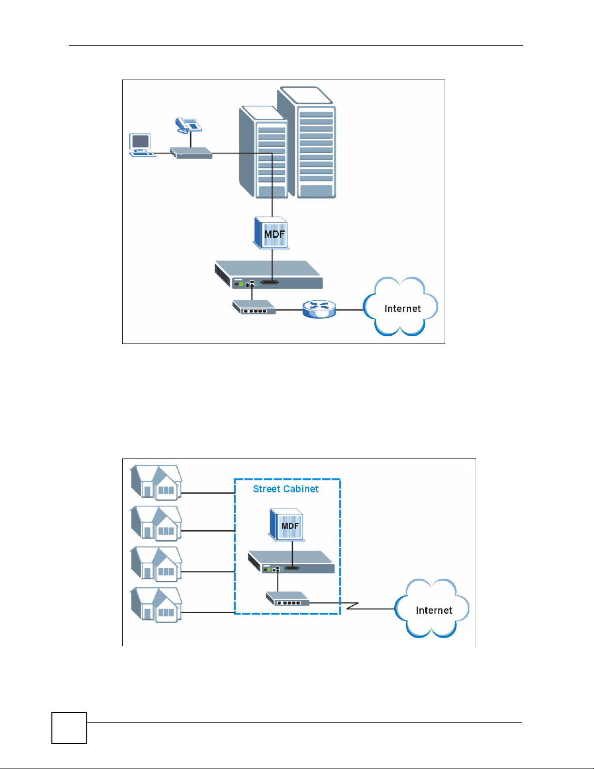
Chapter 1 Getting to Know the IES-612-51A
Figure 1 MTU Application
1.2.2 Curbside Application
The IES-612-51A can be used by an Internet Service Provider (ISP) in a street cabinet to form
a "mini POP (Point-of-Presence)" to provide broadband services to residential areas that are
too far away from the ISP to avail of DSL services. Residents need a DSL modem, connected
as shown in the previous figure.
Figure 2 Curbside Application
42
IES-612-51A User’s Guide

Chapter 1 Getting to Know the IES-612-51A
1.3 Ways to Manage the IES-612-51A
Use any of the following methods to manage the IES-612-51A.
• Web Configurator. This is recommended for everyday management of the IES-612-51A
using a (supported) web browser. See Chapter 4 on page 61.
• Command Line Interface. Line commands offer an alternative to the Web Configurator
and may be necessary to configure advanced features. See Chapter 41 on page 257.
• FTP. Use File Transfer Protocol for firmware upgrades and configuration backup/restore.
See Chapter 50 on page 335.
• SNMP. The IES-612-51A can be monitored and/or managed by an SNMP manager. See
Section 34.3 on page 225.
1.4 Good Habits for Managing the IES-612-51A
Do the following things regularly to make the IES-612-51A more secure and to manage the
IES-612-51A more effectively.
• Change the password. Use a password that’s not easy to guess and that consists of
different types of characters, such as numbers and letters.
• Write down the password and put it in a safe place.
• Back up the configuration (and make sure you know how to restore it). Restoring an
earlier working configuration may be useful if the IES-612-51A becomes unstable or even
crashes. If you forget your password, you will have to use the console port to reset the
IES-612-51A to its factory default settings. If you backed up an earlier configuration file,
you would not have to totally re-configure the IES-612-51A. You could simply restore
your last configuration.
IES-612-51A User’s Guide
43

Chapter 1 Getting to Know the IES-612-51A
44
IES-612-51A User’s Guide

CHAPTER 2
Hardware Installation
This chapter explains how to install the IES-612-51A.
2.1 General Installation Instructions
Before you begin, read all the safety warnings in Safety Wa rnings on page 6, and make sure
you follow them.
Perform the installation as follows:
1 Make sure the IES-612-51A power is not connected.
2 Install the hardware. See Section 2.1 on page 45.
3 See Section 3.1 on page 49 for instructions on making front panel connections.
4 See Section 3.2.5 on page 52 for instructions on connecting the Telco-50 connectors.
2.2 Installation Scenarios
The IES-612-51A can be placed on a desktop or rack-mounted on a standard EIA rack. Use the
rubber feet in a desktop installation and the brackets in a rack-mounted installation.
For proper ventilation, allow at least 4 inches (10 cm) of clearance at the front and 3.4 inches
(8 cm) at the back of the IES-612-51A. This is especially important for enclosed rack
installations.
2.2.1 Desktop Installation Procedure
Do the following to install the IES-612-51A on top of a desk or table. The figures in this
section are examples and are not intended as an exact representation of the IES-612-51A.
1 Make sure the IES-612-51A is clean and dry.
2 Set the IES-612-51A on a smooth, level surface strong enough to support the weight of
the IES-612-51A and the connected cables. Make sure there is a power outlet nearby.
3 Make sure there is enough clearance around the IES-612-51A to allow air circulation
and the attachment of cables and the power cord.
4 Remove the adhesive backing from the rubber feet.
5 Attach the rubber feet to each corner on the bottom of the IES-612-51A. These rubber
feet help protect the IES-612-51A from shock or vibration and ensure space between
IES-612-51A when stacking.
IES-612-51A User’s Guide
45

Chapter 2 Hardware Installation
Figure 3 Attaching Rubber Feet
EXAMPLE
" Do not block the ventilation holes. Leave space between IES-612-51A when
stacking.
2.2.2 Rack-Mounted Installation
2.2.2.1 Rack-mounted Installation Requirements
The IES-612-51A can be mounted on an EIA standard size, 19-inch rack or in a wiring cl oset
with other equipment. Follow the steps below to mount your IES-612-51A on a standard EIA
rack using a rack-mounting kit.
" Make sure the rack will safely support the combined weight of all the
equipment it contains.
" Make sure the position of the IES-612-51A does not make the rack unstable or
top-heavy. Take all necessary precautions to anchor the rack securely before
installing the unit.
• Use a #2 Philips screwdriver to install the screws.
• See Chapter 56 on page 417 for the gauge of wire to use for the frame ground connections.
" Failure to use the proper screws may damage the unit.
46
IES-612-51A User’s Guide

Chapter 2 Hardware Installation
" Do not block the ventilation holes. Leave space between devices when
stacking.
2.2.2.2 Rack-Mounted Installation Procedure
Do the following to rack-mount the IES-612-51A. The figures in this section are examples and
are not intended as an exact representation of the IES-612-51A.
1 Align one bracket with the holes on one side of the IES-612-51A and secure it with the
bracket screws smaller than the rack-mounting screws.
2 Attach the other bracket in a similar fashion.
Figure 4 Attaching Mounting Brackets and Screws
EXAMPLE
3 After attaching both mounting brackets, position the IES-612-51A in the rack by lining
up the holes in the brackets with the appropriate holes on the rack. Secure the IES-61251A to the rack with the rack-mounting screws.
Figure 5 Rack Mounting
EXAMPLE
IES-612-51A User’s Guide
47

Chapter 2 Hardware Installation
48
IES-612-51A User’s Guide

CHAPTER 3
Front Panel
This chapter describes the front panel and rear panel of the IES-612-51A and shows you how
to make the hardware connections.
3.1 Front Panel
The figure below shows the front panel of the IES-612-51A.
Figure 6 Front Panel: AC Input
3.1.1 Front Panel Ports
The following table describes the port labels on the front panel.
Table 1 Front Panel Ports
LABEL DESCRIPTION
CONSOLE Only connect to this port if you want to configure the IES-612-51A using the command
line interface (CLI) via the console port.
LAN 10/100 Connect these ports to a computer, a hub, an Ethernet switch or router.
USER/CO Connect the Telco-50 connector USER pins (14-25, 39-50) to subscribers respectively.
Connect the Telco-50 connector CO pins (1-12, 26-37) to the telephone company for
subscribers respectively.
3.2 LEDs
The following table describes the LEDs on the front panel.
Table 2 LEDs
LED COLOR STATUS DESCRIPTION
ALM Red On The IES-612-51A is functioning abnormally.
Off The IES-612-51A is functioning normally.
IES-612-51A User’s Guide
49

Chapter 3 Front Panel
Table 2 LEDs (continued)
LED COLOR STATUS DESCRIPTION
SYS Green On The IES-612-51A’s system is running.
ETHERNET
(1~2)
ADSL (1~12) Green On The IES-612-51A has a successful DSL connection.
3.2.1 Console Port
For local management, you can use a computer with terminal emulation software configured
to the following parameters:
Blinking The IES-612-51A is booting.
Off The IES-612-51A’s stem is not running.
Green On The IES-612-51A has a successful 10 Mbps connection
on this port.
Blinking The IES-612-51A is sending/receiving data on this port.
Orange On The IES-612-51A has a successful 100 Mbps
connection on this port.
Blinking The IES-612-51A is sending/receiving data on this port.
Blinking The IES-612-51A is looking for a DSL connection.
Off The IES-612-51A does not have a DSL connection.
• VT100 terminal emulation
• 9600 bps
• No parity, 8 data bits, 1 stop bit
• No flow control
Connect the male 9-pin end of the console cable to the console port of the IES-612-51A.
Connect the female end to a serial port (COM1, COM2 or other COM port) of your computer.
3.2.1.1 Default Ethernet Settings
The factory default negotiation settings for the Ethernet ports on the IES-612-51A are:
• Speed: Auto
• Duplex: Auto
50
IES-612-51A User’s Guide

3.2.2 LAN Port (Ethernet) Connection
Connect the LAN port of your IES-612-51A to an Ethernet WAN switch using a straightthrough Category 5 UTP (Unshielded Twisted Pair) cable with RJ-45 connectors.
You may connect multiple IES-612-51A units to the same Ethernet switch (up to the number
of ports available on the Ethernet switch).
3.2.3 Notes About MDFs (Main Distribution Frames)
An MDF is usually installed between end-users' equipment and the telephone company (CO)
in a basement or telephone room. The MDF is the point of termination for the outside
telephone company lines coming into a building and the telephone lines in the building.
Figure 7 MDF Wiring
Chapter 3 Front Panel
• Connect wiring from end-user equipment to the lower ports of an MDF using a telephone
wire. Connect wiring from the telephone company to the upper ports of an MDF (see the
previous figure).
• Some MDFs have surge protection circuitry built in between the two banks; thus, do not
connect telephone wires from the telephone company directly to the IES-612-51A.
• Use a punch-down tool to seat telephone lines between MDF blocks.
3.2.4 Te lco-50 Cables
Telco-50 cables are used for data and voice applications with MDFs (Main Distribution
Frame), patch panels and distribution boxes. They can also be used as extension cables. Telco50 cables are made up of 25 twisted-pair copper wires.
Connect a Telco-50 connector to one end of the cable (see the hardware specifications
appendix for pin assignments) and connect the other end directly to an MDF; alternatively
attach RJ-11 connec to rs an d co nnect directly to DSL modem(s).
IES-612-51A User’s Guide
51

Chapter 3 Front Panel
Figure 8 Telco-50 Cable with RJ-11 Connectors
3.2.5 Telco-50 Connections
The internal DSL splitters separate the voice signals from the DSL signals. They feed the DSL
signals to the IES-612-51A and divert the voice signals to the CO lines of the Telco-50
connector.
Connect the CO lines of the Telco-50 connector to the PBX or PSTN/ISDN switch.
Connect the USER lines of the Telco-50 connector to the subscribers' telephone wiring. In
most multi-tenant unit applications, the USER pins connect to the subscribers' telephone
wiring via Main Distribution Frame (MDF).
See the section on MDF scenarios and the pin assignments in the hardware specifications
appendix for details on Telco-50 connections.
3.2.6 ADSL Connections
Connect the lines from the user equipment (ADSL modems) to the T elco -50 connector USER
pins and the lines from the central office switch or PBX (Private Branch Exchange) to the
Telco-50 connector CO pins. Make sure that the USER line and the CO lines are not shorted
on the MDF (Main Distribution Frame).
The line from the user carries both the ADSL and the voice signals. For each line, the IES612-51A has a built-in splitter that separates the high frequency ADSL signal from the voice
band signal and feeds the voice band signal to the CO port.
52
The following figure gives an overview on a possible installation scenario for the IES-61251A. Data and voice signals can coexist on the same telephone wiring.
IES-612-51A User’s Guide

Figure 9 Installation Overview
Chapter 3 Front Panel
" You can also attach RJ-11 connectors to the Telco-50 cable and connect
directly to a DSL modem(s) or patch panel. This chapter discusses
connections using MDFs.
3.2.7 Typical MDF Scenarios
This section describes typical installation scenarios.
3.2.7.1 Installation Scenario A
You want to install the IES-612-51A in an environment where there are no previously installed
MDFs. There is no phone service and you want to install the IES-612-51A for data-access
only. No connections from the CO lines are necessary.
You may connect using an MDF or attach RJ-11 connectors to the non-IES-612-51A end of
the Telco-50 cable and then connect to DSL modems directly.
IES-612-51A User’s Guide
53

Chapter 3 Front Panel
Figure 10 Installation Scenario A
3.2.7.1.1 Procedure To Connect To An MDF
1 Connect the Telco-50 connector end of the cable to the Telco-50 connector.
2 Connect the USER wiring on the other end of the Telco-50 cable to the upper ports of the
MDF using a punch-down tool.
3 Connect the telephone wiring from each end-user's DSL modem to the lower ports of the
MDF.
3.2.7.2 Installation Scenario B
Phone service is available. There is one MDF from which end-users CO connections are made
(see next figure).
54
IES-612-51A User’s Guide

Chapter 3 Front Panel
Figure 11 One MDF for End-user and CO Connections
This installation scenario requires three MDFs. Please refer to the following figure for the
connection schema.
• MDF 1 is the original MDF used for telephone connections only.
• MDF 2 is used for telephone connections only.
• MDF 3 is for ADSL service connections.
" Change the wiring (in the following figure) from MDF 1 to MDF 3 for telephone
subscribers who want ADSL service.
IES-612-51A User’s Guide
55

Chapter 3 Front Panel
Figure 12 Installation Scenario B
3.2.7.2.1 Procedure To Connect To MDFs
1 Connect the Telco-50 connector end of the cable to the Telco-50 connector.
2 Connect the USER wiring on the other end of the Telco-50 cable to the upper ports of
MDF 3 using a punch-down tool.
3 Connect the telephone wiring from the end-user's DSL modem(s) to the lower ports of
MDF 3.
4 Connect the CO wiring of the T elco-50 cable to th e lower ports of MDF 2 using a punch-
down tool.
5 Connect the upper ports of MDF 2 to the lower ports of MDF 1 using telephone wires.
6 Connect the upper ports of MDF 1 to the telephone company.
7 Telephone subscribers only (non-DSL subscribers) retain connections to the lower ports
of MDF 1.
8 Change the wiring from MDF 1 to MDF 3 for telephone subscribers who want DSL
service.
3.2.7.3 Installation Scenario C
Phone service is also available but there are two MDFs; one for end-user telephone line
connections and the other one for CO telephone wiring connections (see the following figure).
56
IES-612-51A User’s Guide

" Users A and B have telephone (only) service.
Figure 13 Two Separate MDFs for End-user and CO Connections
This installation scenario requires four MDFs. Please refer to the following figure for the DSL
connection schema.
Chapter 3 Front Panel
• MDFs 1 and 2 are the two original MDFs.
• MDFs 3 and 4 are two additional MDFs you need.
" User A still has telephone service only. User B now has telephone and DSL
service (see the following figure).
IES-612-51A User’s Guide
57

Chapter 3 Front Panel
Figure 14 Installation Scenario C
3.2.7.3.1 Procedure To Connect To MDFs
1 Connect the Telco-50 connector end of the cable to the Telco-50 connector.
2 Connect the USER wiring on the other end of the Telco-50 cable to the upper ports of
MDF 3 using a punch-down tool.
3 Connect the lower ports of MDF 3 to the upper ports of MDF 2 for those users that want
DSL service. (Users who want telephone service only, retain the original connection
from the top port of MDF 2 to the bottom port of MDF 1.)
4 Connect the telephone wiring from the end-user's DSL equipment to the lower ports of
MDF 2.
5 Connect the CO wiring of the T elco-50 cable to th e lower ports of MDF 4 using a punch-
down tool.
6 Connect the top ports of MDF 4 to the bottom ports of MDF 1 using telephone wires.
7 Connect the top ports of MDF 1 to the telephone company.
58
IES-612-51A User’s Guide

PART II
Basic Settings
Introducing the Web Configurator (61)
Initial Configuration (69)
Home and Port Statistics Screens (75)
System Information (87)
General Setup (91)
User Account (93)
Switch Setup (97)
IP Setup (103)
ENET Port Setup (105)
xDSL Port Setup (107)
xDSL Profiles Setup (125)
xDSL Line Data (137)
59

60

CHAPTER 4
Introducing the Web
Configurator
This chapter tells how to access and navigate the web configurator.
4.1 Web Configurator Overview
The web configurator allows you to use a web browser to manage the IES-612-51A.
4.2 Screen Privilege Levels
There is a high or low privilege level for each screen.
High privilege screens are only available to administrators with high privilege access. High
privilege screens include things like creating administrator accounts, restarting the system,
saving changes to the nonvolatile memory and resetting to factory defaults. Nonvolatile
memory refers to the IES-612-51A’s storage that remains even if the IES-612-51A’s power is
turned off. Administrators with high privilege access can use all screens including the lower
privilege screens.
Administrators with the low privilege level are restricted to using only low privilege screens.
Low privilege screens are read only.
4.3 Accessing the Web Configurator
Use Internet Explorer 6 and later versions with JavaScript enabled.
Use the following instructions to log on to the web configurator.
1 Launch your web browser, and enter the IP address of the IES-612-51A (default:
192.168.1.1 is the factory default) in the Location or Address field. Press Enter. The
Login screen appears.
IES-612-51A User’s Guide
61

Chapter 4 Introducing the Web Configurator
Figure 15 Login
2 Type admin in the User Name field and your password (default: 1234) in the Password
field. Click OK. The main screen appears.
This is the web configurator’s main screen.
Figure 16 Home
B
C
A
A - Click the menu items to open submenu links, and then click o n a submenu link to open the
screen in the main window. See Section 4.4 on page 63 for more information.
B - Click this to open the Home screen. (This is the same screen that is displayed above.) See
Chapter 6 on page 75 for more information.
C - Click this to log out of the web configurator.
62
IES-612-51A User’s Guide

Chapter 4 Introducing the Web Configurator
4.4 Navigation Panel
In the navigation panel, click a menu item to reveal a list of submenu links. Click a submenu
link to go to the corresponding screen.
Table 3 Navigation Panel Submenu Links
BASIC SETTING ADVANCED APPLICATION ROUTING PROTOCOL
ALARM MANAGEMENT CONFIG SAVE
The following table briefly describes the functions of the screens that you open by clicking the
navigation panel’s sub-links.
Table 4 Web Configurator Screens
LABEL DESCRIPTION
Basic Setting
System Information Use this screen to display general system and hardware monitoring information.
General Setup Use this screen to configure general identification information about the device
and the time and date settings.
User Account Use this screen to configure system administrator accounts.
Switch Setup Use this screen to set up system-wide parameters such as MAC address
learning and priority queues.
IES-612-51A User’s Guide
63

Chapter 4 Introducing the Web Configurator
Table 4 Web Configurator Screens (continued)
LABEL DESCRIPTION
IP Setup Use this screen to configure the system and management IP addresses and
subnet masks.
ENET Port Setup Use this screen to configure settings for the Ethernet ports.
xDSL Port Setup Use these screens for configuring settings for individual DSL ports.
xDSL Profiles Setup Use these screens for configuring profiles for the DSL ports.
xDSL Line Data Use these screens for viewing DSL line operating values, bit allocation and
Advanced
Application
VLAN Use these screens for viewing and configuring the VLAN settings.
IGMP Use these screens to view IGMP status information and configure IGMP
Static Multicast Use this screen to configure static multicast entries.
Multicast VLAN Use these screens to set up multicast VLANs that can be shared among
Filtering Use this screen to configure packet filtering.
MAC Filter Use this screen to configure MAC filtering for each port.
Spanning Tree
Protocol
Port Authentication Use these screens to configure RADIUS and IEEE 802.1x security settings.
Port Security Use this screen to limit the number of MAC address that can be learned on a
DHCP Relay Use this screen to configure the DHCP relay settings.
DHCP Snoop Use these screens to drop traffic from IP addresses not assigned by the DHCP
2684 Routed Mode Use this screen to configure the IES-612-51A to handle 2684 routed mode
PPPoA to PPPoE Use this screen to enable PPPoA-to-PPPoE conversions on each port.
DSCP Use this screen to set up DSCP on each port and to convert DSCP values to
TLS PVC Use this screen to set up Transparent LAN Service (VLAN stacking, Q-in-Q) on
ACL Use this screen to set up Access Control Logic profiles and to assign them to
Downstream
Broadcast
SysLog Use this screen to configure the syslog settings.
Access Control Use this screen to configure service access control and configure SNMP and
Routing Protocol
Static Routing Use this screen to configure static routes. A static route defines how the IES-
Alarm
performance counters.
settings and IGMP filters. You can also use these screens to set up bandwidth
requirements by multicast group or port and to set up limits on the number of
multicast groups to which a port can subscribe.
different subscriber VLANs on the network.
Use these screens to display Rapid Spanning Tree Protocol (RSTP) information
and configure RSTP settings.
port.
server and to look at a summary of the DHCP packets on each port.
traffic.
IEEE 802.1p values.
each port.
each PVC.
Use this screen to block downstream broadcast packets from being sent to
specified VLANs on specified ports.
remote management.
612-51A should forward traffic by configuring the TCP/IP parameters manually.
64
IES-612-51A User’s Guide

Chapter 4 Introducing the Web Configurator
Table 4 Web Configurator Screens (continued)
LABEL DESCRIPTION
Alarm Status Use these screens to view the alarms that are currently in the system.
Alarm Event Setup Use these screens to view and set the severity levels of the alarms and where
Alarm Port Setup Use this screen to set the alarm severity threshold for recording alarms on an
Management
Maintenance Use this screen to perform firmware and configuration file maintenance as well
Diagnostic Use this screen to view system logs and test port(s).
MAC Table Use this screen to view the MAC addresses of devices attached to what ports.
ARP Table Use this screen to view the MAC address to IP address resolution table.
Config Save
Config Save Use this screen to save the device’s configuration into the nonvolatile memory
the system is to send them.
individual port(s).
as restart the system.
(the IES-612-51A’s storage that remains even if the IES-612-51A’s power is
turned off).
4.5 Changing Your Password
After you log in for the first time, it is recommended you change the default administrator
password. Click Basic Setting and then User Account to display the User Account screen.
Figure 17 User Account
Click the index number 1 to edit the default administrator account settings.
IES-612-51A User’s Guide
65
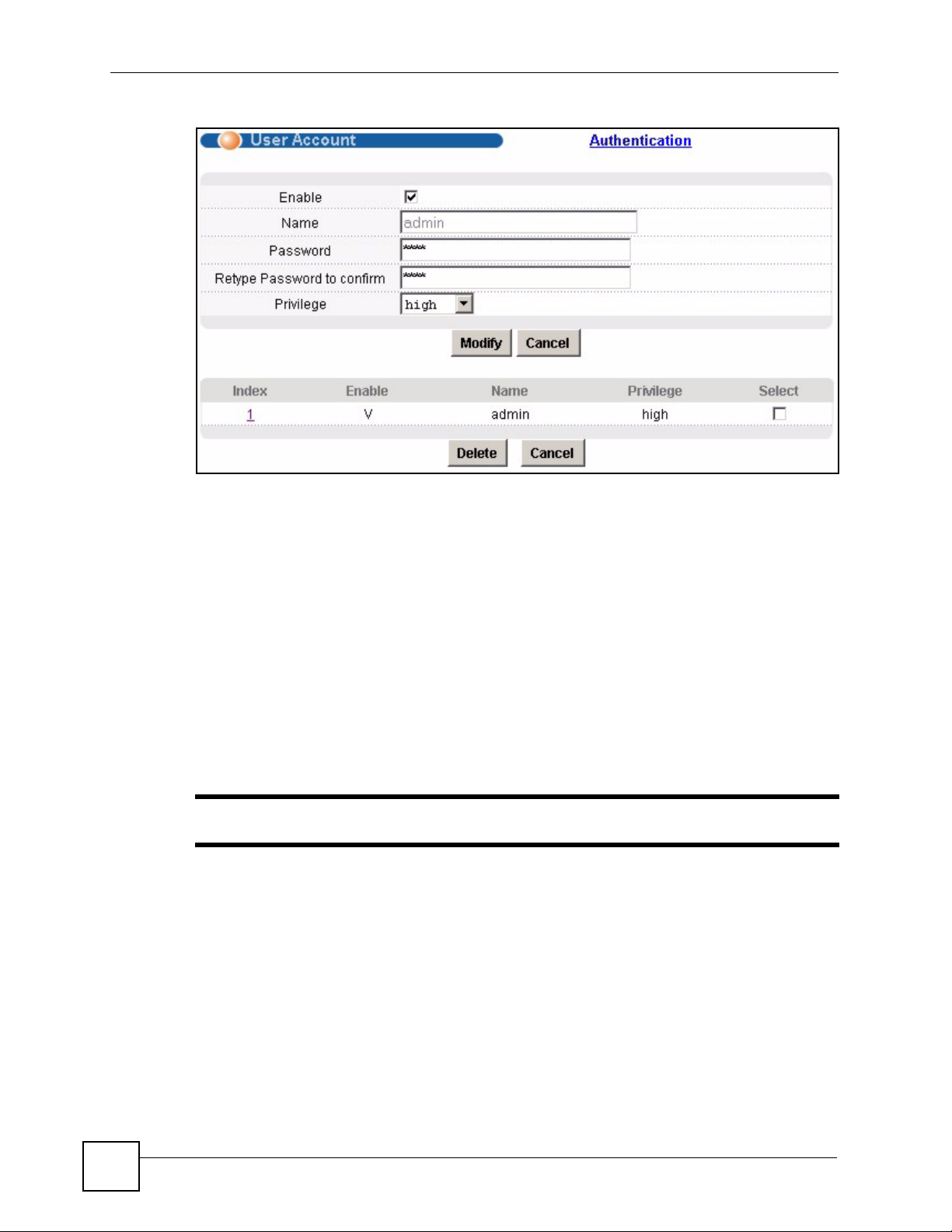
Chapter 4 Introducing the Web Configurator
Figure 18 User Account
Enter the new password in the Password and Retype Password to confirm fields, and click
Modify. Do not forget to click Config Save before you exit t he web configurator. See Section
4.6 on page 66.
4.6 Saving Your Configuration
Click Apply in a configuration screen when you are done modifying the settings in that screen
to save your changes back to the run-time memory. Settings in the run-time memory are lost
when the IES-612-51A’s power is turned off.
Click Config Save in the navigation panel to save your configuration to nonvolatile memory.
Nonvolatile memory refers to the IES-612-51A’s storage that remains even if the IES-61251A’s power is turned off.
" Use Config Save when you are done with a configuration session.
4.7 Logging Out of the Web Configurator
Click Logout in any screen to exit the web configurator. You have to log in with your
password again after you log out. This is recommended after you finish a management session
both for security reasons and so you do not lock out other device administrators.
66
IES-612-51A User’s Guide

Figure 19 Logout
Chapter 4 Introducing the Web Configurator
IES-612-51A User’s Guide
67

Chapter 4 Introducing the Web Configurator
68
IES-612-51A User’s Guide

CHAPTER 5
Initial Configuration
This chapter describes initial configuration for the IES-612-51A. See Chapter 56 on page 417
for various default settings of the IES-612-51A.
5.1 Initial Configuration Overview
This chapter shows what you first need to do to provide service to DSL subscribers.
5.2 Initial Configuration
This chapter uses the web configurator for initial configuration. See the CLI chapters for
information on the commands. Use Internet Explorer 6 and later versions with JavaScript
enabled.
1 Log in to the web configurator. See Section 4.3 on page 61 for instructions.
2 In the navigation panel, click Basic Setting, IP Setup. The IP Setup screen appears.
Figure 20 IP Setup
3 Use this screen to change the IP address, subnet mask, and default gateway IP address
for your network. Apply the settings.
IES-612-51A User’s Guide
69

Chapter 5 Initial Configuration
" If you change the IP address of the IES-612-51A, after you click Apply IP
setting, you have to use the new IP address to log into the web configurator
again.
4 If your subscribers use VPI 0 and VCI 33 (the default for all of the DSL ports), go to step
13. Otherwise, use the following steps to change the VPI and VCI settings for all of the
DSL ports.
First, you will delete the default virtual channel from all of the DSL ports. (You cannot edit it).
Then, you will configure a new virtual channel for a port and copy it to the other DSL ports.
Adding another virtual channel without deleting the default virtual channel is not
recommended since you cannot set the new channel to be the port’s super channel. The super
channel can forward frames belonging to multiple VLAN groups (that are not assigned to
other channels). A channel that is not the super channel can only forward frames with a single
VLAN ID (that is configured on that channel). In this case, the IES-612-51A drops an y frames
received from the subscriber that are tagged with another VLAN ID.
5 In the navigation panel, click Basic Setting, xDSL Port Setup. The xDSL Port Setup
screen appears.
Figure 21 xDSL Port Setup
6 Click VC Setup. The following screen appears.
70
IES-612-51A User’s Guide

Figure 22 VC Setup
Chapter 5 Initial Configuration
7 Select any virtual channel’s Select radio button, and click Delete. The following screen
appears.
Figure 23 VC Setup, Delete
8 Click OK. The following screen appears.
Figure 24 Select Ports
IES-612-51A User’s Guide
71

Chapter 5 Initial Configuration
9 Click All, and then click Apply. The VC Setup screen is updated.
Figure 25 VC Setup
10Select Super Channel to allow the channel to forward frames belonging to multiple
VLAN groups (that are not assigned to other channels). Then, enter the VPI and VCI that
you use. Leave the other default settings, and click Add. The VC Setup screen is
updated.
Figure 26 VC Setup
11 Select the new channel’s Select radio button. Click Copy, and then click Paste. The
following screen appears. The following screen appears.
72
IES-612-51A User’s Guide

Chapter 5 Initial Configuration
Figure 27 Select Ports
12Click All, and then click Apply. The VC Setup screen is updated.
Figure 28 VC Setup
13Click Config Save, Config Save. The Config Save screen appears.
Figure 29 Config Save
14Click Save. The following screen should appear.
IES-612-51A User’s Guide
73

Chapter 5 Initial Configuration
Figure 30 Config Save, Save Successful
You can now use the device (with the other settings set to the defaults) to provide service to
DSL subscribers. See Section 56.4 on page 423 for information on other default settings.
74
IES-612-51A User’s Guide
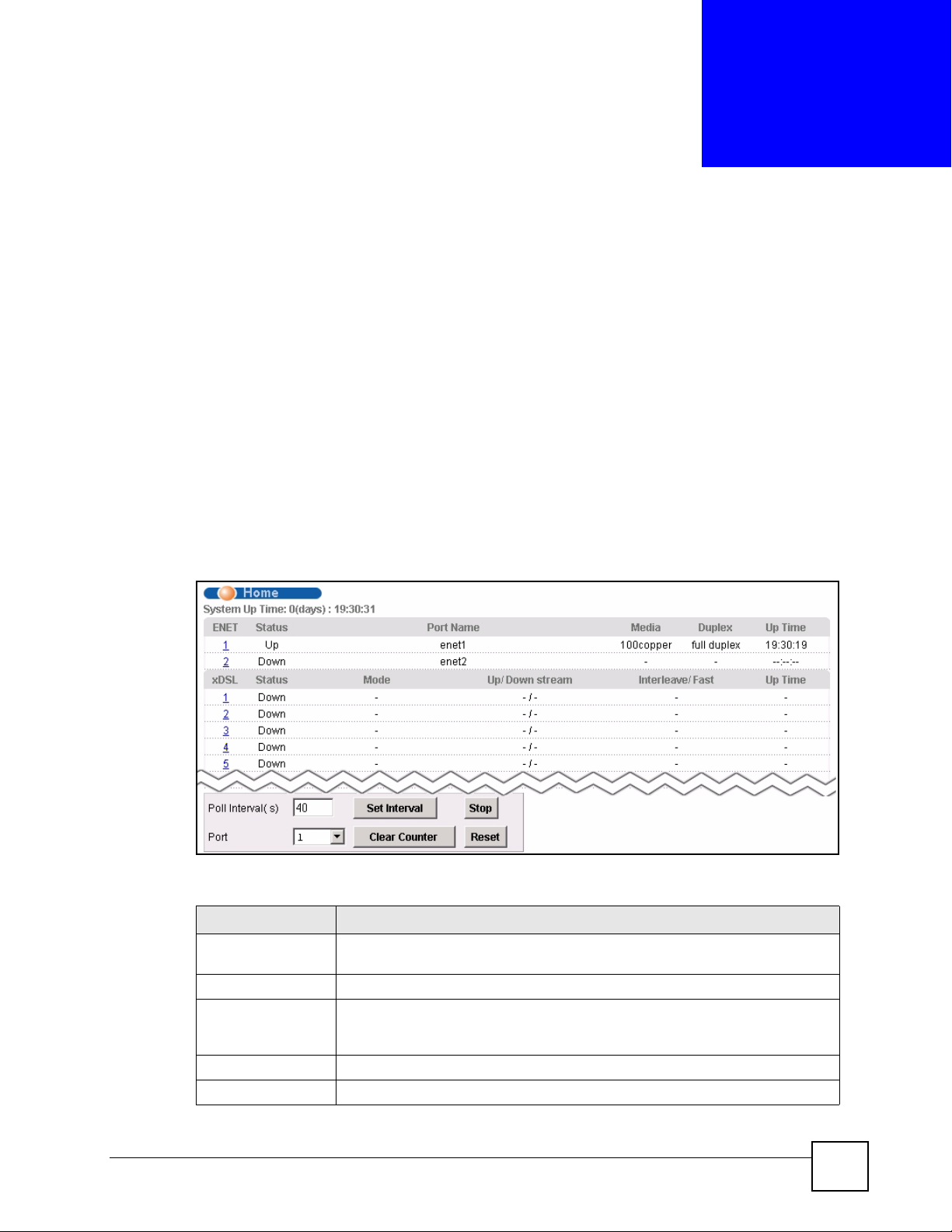
CHAPTER 6
Home and Port Statistics
Screens
This chapter describes the Home (status), Port Statistics, and RMON screens.
6.1 Home Screen
The Home screen of the web configurator displays a port statistical summary with links to
each port showing statistical details.
To open this screen, click Home in any web configurator screen.
Figure 31 Home
The following table describes the labels in this screen.
Table 5 Home
LABEL DESCRIPTION
System up Time This field shows how long the system has been running since the last time it
ENET This field displays the number of the Ethernet port. Click a port number to
Status This field displays whether the Ethernet port is connected (Up) or not (Down).
Port Name This field displays the name of the Ethernet port.
IES-612-51A User’s Guide
was started.
The following fields are related to the Ethernet ports.
display that port’s statistics screen. The Ethernet Port Statistics Screen appears.
See Section 6.1.1 on page 76.
75

Chapter 6 Home and Port Statistics Screens
Table 5 Home (continued)
LABEL DESCRIPTION
Media This field displays the type of media that this Ethernet port is using for a
connection. “-“ displays when the port is disabled or not connected.
Duplex This field displays whether the port is using half or full-duplex communication. “-
“ displays when the port is disabled or not connected.
Up Time This field shows the total amount of time in hours, minutes and seconds the
port’s connection has been up. “--:--:--“ displays when the port is disabled or not
connected.
The following fields are related to the xDSL ports.
xDSL This identifies the xDSL port. Click a port number to display that port’s statistics
Status This field shows whether the port is connected (Up) or not (Down).
Mode This field shows which ADSL operational mode the port is set to use. “-“
Up/Down stream This field shows the number of kilobits per second that a port is set to transmit
Interleave/Fast This field shows the port’s ADSL latency mode (fast or interleave).
Up Time This field shows the total amount of time in hours, minutes and seconds the
Poll Interval(s)
Set Interval
Stop Click Stop to halt system statistic polling.
Port
Clear Counter
Reset Click this to set the Poll Interval(s) and Port fields to their default values and to
screen. The DSL Port Statistics Screen appears. See Section 6.1.2 on page 79.
displays when the port is not connected.
and receive.
port’s connection has been up. “-“ displays when the port is not connected.
The following fields and buttons apply to the whole screen.
The text box displays how often (in seconds) this screen refreshes. You may
change the refresh interval by typing a new number in the text box and then
clicking Set Interval.
Select a port from the Port drop-down list box and then click Clear Counter to
erase the recorded statistical information for that port.
refresh the screen.
6.1.1 Ethernet Port Statistics Screen
Use this screen to display statistics about an Ethernet port. To open this screen, click an
Ethernet port’s number in the Home screen.
76
IES-612-51A User’s Guide

Figure 32 Port Statistics (Ethernet)
Chapter 6 Home and Port Statistics Screens
The following table describes the labels in this screen.
Table 6 Port Statistics (Ethernet)
LABEL DESCRIPTION
RMON Click this to open the RMON Statistics screen.
Return Click this to go back to the Home screen.
Port Use this drop-down list box to select a port for which you wish to view statistics.
This field identifies the port described in this screen.
Port Name This field displays the name that you have configured for the port.
Rx bytes This field shows the number of octets of Ethernet frames received that are from
0 to 1518 octets in size, counting the ones in bad packets, not counting framing
bits but counting FCS (Frame Check Sequence) octets. An octet is an 8-bit
binary digit (byte).
Rx packets This field shows the number of packets received on this port (including
multicast, unicast, broadcast and bad packets).
Rx error fcs This field shows the number of frames received with an integral length of 64 to
1518 octets and containing a Frame Check Sequence error.
Rx multicast This field shows the number of good multicast frames received of 64 to 1518
Rx broadcast This field shows the number of good broadcast frames received of 64 to 1518
octets in length (for non VLAN) or 1522 octets (for VLAN), not including
Broadcast frames. Frames with range or length errors are also not taken into
account.
octets in length (for non VLAN) or 1522 octets (for VLAN), not including
multicast frames. Frames with range or length errors are also not taken into
account.
IES-612-51A User’s Guide
77

Chapter 6 Home and Port Statistics Screens
Table 6 Port Statistics (Ethernet) (continued)
LABEL DESCRIPTION
Rx mac pause This field shows the number of valid IEEE 802.3x Pause frames received on this
port.
Rx fragments This field shows the number of frames received that were less than 64 octets
long, and contained an invalid FCS, including non-integral and integral lengths.
Rx error overrun This field shows how many times an Ethernet transmitter overrun occurred.
Rx error mru This field shows the number of received frames that were dropped due to
Rx dropped This field shows the number of received frames that were received into the IES-
Rx jabber This field shows the number of frames received that were longer than 1518
Rx error alignment This field shows the number of frames receiv ed that were 64 to 1518 (non
Rx oversize This field shows the number of frames received that were bigger than 1518 (non
Rx undersize This field shows the number of frames received that were less than 64 octets
Rx discard This field shows the number of frames dropped based on packet filtering.
Tx bytes This field sh ows the number of bytes that have been transmitted on this port.
Tx packets This field shows the number of packets transmitted on this port.
Tx multicast This field shows the number of good multicast frames transmitted on this port
Tx broadcast This field shows the number of broadcast frames transmitted on this port (not
Tx mac_pause This field shows the number of valid IEEE 802.3x Pause frames transmitted on
Tx fragments This field shows the number of transmitted frames that were less than 64 octets
Tx frames This field shows the number of complete good frames transmitted on this port.
Tx error underrun This field shows the number of outgoing frames that were less than 64 octets
Tx undersize This field shows the number of frames transmitted that were less than 64 octets
Tx jabber This field shows the number of frames transmitted that were longer than 1518
Tx oversize This field shows the number of frames transmitted that were bigger than 1518
packet(<=64) This field shows the number of frames received and transmitted (including bad
packet(65-127) This field shows the number of frames received and transmitted (including bad
exceeding the Maximum Receive Unit frame size.
612-51A, but later dropped because of a lack of system resources.
octets (non VLAN) or 1522 octets (VLAN) and contained an invalid FCS,
including alignment errors.
VLAN) or 1522 (VLAN) octets long but contained an invalid FCS and a non-
integral number of octets.
VLAN) or 1522 (VLAN) octets and contained a valid FCS.
long and contained a valid FCS.
This includes collisions but not jam signal or preamble/SFD (Start of Frame
Delimiter) bytes.
(not including broadcast frames).
including multicast frames).
this port.
long, and with an incorrect FCS value.
long.
long and contained a valid FCS.
octets (non VLAN) or 1522 octets (VLAN) and contained an incorrect FCS
value.
octets (non VLAN) or 1522 (VLAN) and contained a valid FCS.
frames) that were 64 octets or less in length (this includes FCS octets but
excludes framing bits).
frames) that were 65 to 127 octets in length (this includes FCS octets but
excludes framing bits).
78
IES-612-51A User’s Guide

Chapter 6 Home and Port Statistics Screens
Table 6 Port Statistics (Ethernet) (continued)
LABEL DESCRIPTION
packet(128-255) This field shows the number of frames received and transmitted (including bad
frames) that were 128 to 255 octets in length (this includes FCS octets but
excludes framing bits).
packet(256-511) This field shows the number of frames received and transmitted (including bad
frames) that were 256 to 511 octets in length (this includes FCS octets but
excludes framing bits).
packet(512-1023) This field shows the number of frames received and transmitted (including bad
frames) that were 512 to 1023 octets in length (this includes FCS octets but
excludes framing bits).
packet(1024-1518) This field shows the number of frames received and transmitted (including bad
frames) that were 1024 to 1518 octets in length (this includes FCS octets but
excludes framing bits).
packet(1522) This field shows the number of frames received and transmitted (including bad
frames) that were 1519 to 1522 octets in length (this includes FCS octets but
excludes framing bits).
packet(total) This field shows the total number of received and transmitted packets.
broadcast(total) This field shows the total number of received and transmitted broadcast frames.
multicast(total) This field shows the total number of received and transmitted multicast frames.
octet(total) This field shows the total number of received and transmitted octets (unicast,
multicast and broadcast).
Poll Interval(s)
Set Interval
Stop Click Stop to halt system statistic polling.
Port
Clear Counter
Reset Click this to set the Poll Interval(s) and Port fields to their default values and to
The text box displays how often (in seconds) this screen refreshes. You may
change the refresh interval by typing a new number in the text box and then
clicking Set Interval.
Select a port from the Port drop-down list box and then click Clear Counter to
erase the recorded statistical information for that port.
refresh the screen.
6.1.2 DSL Port Statistics Screen
Use this screen to display statistics about a DSL port. To open this screen, click a DSL port’s
number in the Home screen.
IES-612-51A User’s Guide
79

Chapter 6 Home and Port Statistics Screens
Figure 33 Port Statistics (DSL)
The following table describes the labels in this screen.
Table 7 Port Statistics (DSL)
LABEL DESCRIPTION
RMON Click this to open the RMON Statistics screen.
Return Click this to go back to the Home screen.
xDSL Port Use this drop-down list box to select a port for which you wish to view statistics.
This field identifies the port described in this screen.
Port Name This field displ ays the name that you have configured for the port. If you have
Tx packets This field shows the number of packets transmitted on this port.
Rx packets This field shows the number of packets received on this port.
Tx broadcast
packets
Rx broadcast
packets
Tx discard packets This field shows the number of outgoing packets that were dropped on this port.
not configured a name, it is blank.
This field shows the number of broadcast packets transmitted on this port.
This field shows the number of broadcast packets received on this port.
The “Tx discard packets” counter always displays “0” because the IES-612-51A
does not discard packets that it sends.
80
IES-612-51A User’s Guide

Chapter 6 Home and Port Statistics Screens
Table 7 Port Statistics (DSL) (continued)
LABEL DESCRIPTION
Rx discard packets This field shows the number of received packets that were dropped on this port.
Some of the possible reasons for the discarding of received (rx) packets are:
• The packet filter is enabled and the packets matched a packet filter.
• The MAC filter is enabled and the IES-612-51A dropped the packets
according to the MAC filter’s configuration.
• The packets contained frames with an invalid VLAN ID.
Errors This field shows the number of AAL5 frames received with CRC errors.
Tx rate This field sh ows the number of kilobytes per second transmitted on this port.
Rx rate This field shows the number of kilobytes per second received on this port.
Tx bytes This field sh ows the number of bytes that have been transmitted on this port.
Rx bytes This field shows the number of bytes that have been received on this port.
VPI/VCI This field displays the Virtual Path Identifier (VPI) and Virtual Circuit Identifier
(VCI) of channels on this port.
Tx Packets This field shows the number of packets transmitted on each channel.
Rx Packets This field shows the number of packets received on each channel.
Tx rate This field shows the number of bytes per second transmitted on each channel.
Rx rate This field shows the number of bytes per second received on each channel.
Tx cells This field shows the number of ATM cells transmitted on each channel.
Rx cells This field shows the number of ATM cells received on each channel.
Errors This field shows the number of error packets on each channel.
Poll Interval(s)
Set Interval
Stop Click Stop to halt system statistic polling.
Port
Clear Counter
Reset Click this to set the Poll Interval(s) and Port fields to their default values and to
The text box displays how often (in seconds) this screen refreshes. You may
change the refresh interval by typing a new number in the text box and then
clicking Set Interval.
Select a port from the Port drop-down list box and then click Clear Counter to
erase the recorded statistical information for that port.
refresh the screen.
6.1.3 RMON Statistics Screen
Use this screen to display RMON statistics about a port. To open this screen, click RMON in
the DSL Port Statistics screen or Ethernet Port Statistics screen.
IES-612-51A User’s Guide
81

Chapter 6 Home and Port Statistics Screens
Figure 34 Port Statistics (RMON)
The following table describes the labels in this screen.
Table 8 Port Statistics (RMON)
LABEL DESCRIPTION
Port Statistics Click this to go back to the previous screen.
Enet1 Click this to look at the RMON history for this port.
Enet2 Click this to look at the RMON history for this port.
EtherStatsDropEvent s This field displays the total number of packets that were dropped on
this port.
EtherStatsOctets This field displays the total number of octets received/transmitted on
EtherStatsPkts This field displays the total number of good packets received/
EtherStatsBroadcastPkts This field displays the total number of broadcast packets received/
EtherStatsMulticastPkts This field displays the total number of multicast packets received/
EtherStatsCRCAlignErrors This field displays the total number of CRC (Cyclical Redundancy
EtherStatsUndersizePkts This field displays the total number of packets that were too small
this port.
transmitted on this port.
transmitted on this port.
transmitted on this port.
Check) alignment errors on this port.
received/transmitted on this port.
82
IES-612-51A User’s Guide

Chapter 6 Home and Port Statistics Screens
Table 8 Port Statistics (RMON) (continued)
LABEL DESCRIPTION
EtherStatsOversizePkts This field displ ays the total number of packets that were too big
received/transmitted on this port.
EtherStatsFragments This is the number of frames received/transmitted that were less than
64 octets long, and contained an invalid FCS, including non-integral
and integral lengths.
EtherStatsJabbers This is the number of frames received/transmitted that were longer
EtherStatsCollisions This is the number of frames for which transmission failed due to
EtherStats64Octets This is the number of frames received/transmitted (including bad
EtherStats65to127Octets This is the number of frames received/transmitted (including bad
EtherStats128to255Octets This is the number of frames received and transmitted (including bad
EtherStats256to511Octets This is the number of frames received/transmitted (including bad
EtherStats512to1023Octet s This is the number of frames received/transmitted (including bad
EtherStats1024to1518Octets This is the number of frames received/transmitted (including bad
Poll Interval(s)
Set Interval
Stop Click Stop to halt system statistic polling.
Port
Clear Counter
Reset Click this to set the Poll Interval(s) and Port fields to their default
than 1518 octets (non VLAN) or 1522 octets (VLAN) and contained an
invalid FCS, including alignment errors.
excessive collisions. Excessive collision is defined as the number of
maximum collisions before the retransmission count is reset.
frames) that were 64 octets or less in length (this includes FCS octets
but excludes framing bits).
frames) that were 65 to 127 octets in length (this includes FCS octets
but excludes framing bits).
frames) that were 128 to 255 octets in length (this includes FCS octets
but excludes framing bits).
frames) that were 256 to 511 octet s in length (this includes FCS octets
but excludes framing bits).
frames) that were 512 to 1023 octets in length (this includes FCS
octets but excludes framing bits).
frames) that were 1024 to 1518 octets in length (this includes FCS
octets but excludes framing bits).
The text box displays how often (in seconds) this screen refreshes.
Y ou may change the refresh interval by typing a new number in the text
box and then clicking Set Interval.
Select a port from the Port drop-down list box and then click Clear
Counter to erase the recorded statistical information for that port.
values and to refresh the screen.
6.1.4 RMON History Screen
Use this screen to display general information (such as sample time) on history samples. To
open this screen, click any port number in the RMON Statistics screen.
IES-612-51A User’s Guide
83

Chapter 6 Home and Port Statistics Screens
Figure 35 Port Statistics (RMON History))
The following table describes the labels in this screen.
Table 9 Port Statistics (RMON History)
LABEL DESCRIPTION
Index:Interval Select the index of the sample interval and the desired data sampling time (in
seconds).
Apply Click this to use the selected data sampling time.
Refresh Click this to update this screen.
Sample Index This field display the sample number.
Interval Start This field displays the data sampling time.
Pkts This field displays the number of packets received or transmitted since the last
sample time.
BroadcastPkts This field displays the number of broadcast packets received or transmitted
MulticastPkts This field displays the number of multicast packets received/transmitted since
Utilization This field displays the port utilization status.
since the last sample time.
the last sample time.
6.1.5 RMON History Detail Screen
Use this screen to display detailed RMON history . To open this screen, click any index number
in the RMON History screen.
84
IES-612-51A User’s Guide

Figure 36 Port Statistics (RMON History Detail))
Chapter 6 Home and Port Statistics Screens
The following table describes the labels in this screen.
Table 10 Port Statistics (RMON History Detail)
LABEL DESCRIPTION
UP Click this to return to the previous screen.
Refresh Click this to update this screen.
Index This field displays the index of the sample interval.
Sample Index This field displays the sample number.
Interval Start This field displays the data sampling time.
Drop Events This field displays the total number of packets that were dropped in the
sampling period.
Octets This field displays the total number of octets received/transmitted in the
Pkts This field displays the total number of good packets received/transmitted in the
BroadcastPkts This field displays the total number of broadcast packets received/transmitted in
MulticastPkts This field displays the total number of multicast packets received/transmitted in
CRCAlignErrors This field displays the total number of CRC (Cyclical Redundancy Check)
UndersizePkts This field displays the total number of packets that were too small received/
OversizePkts This field displays the total number of packets that were too big received/
Fragments This is the number of frames received/transmitted that were less than 64 octets
sampling period.
sampling period.
the sampling period.
the sampling period.
alignment errors in the sampling period.
transmitted in the sampling period.
transmitted in the sampling period.
long, and contained an invalid FCS, including non-integral and integral lengths.
IES-612-51A User’s Guide
85

Chapter 6 Home and Port Statistics Screens
Table 10 Port Statistics (RMON History Detail) (continued)
LABEL DESCRIPTION
Jabbers This is the number of frames received/transmitted that were longer than 1518
octets (non VLAN) or 1522 octets (VLAN) and contained an invalid FCS,
including alignment errors.
Collisions This is the number of frames for which transmission failed due to excessive
collisions. Excessive collision is defined as the number of maximum collisions
before the retransmission count is reset.
Utilizations This field displays the port utilization status in the sampling period.
86
IES-612-51A User’s Guide

CHAPTER 7
System Information
The System Information screen displays general device information (such as firmware
version number) and hardware polling information (such as temperature status). You can
check the firmware version number and monitor the hardware status in this screen.
To open this screen, click Basic Setting, System Information.
Figure 37 System Info
IES-612-51A User’s Guide
87

Chapter 7 System Information
The following table describes the labels in this screen.
Table 11 System Info
LABEL DESCRIPTION
System Name This field displays the device's model name.
ZyNOS F/W Version This field displays the version number of the device’s current firmware including
DSP Code Version This field displays the Digital Signal Processor firmware version number . This is
Hardware Version This is the version of the physical device hardware. This field may be blank.
Serial Number This is the individual identification number assigned to the device at the factory.
Ethernet Address This field refers to the Ethernet MAC (Media Access Control) address of the
Hardware Monitor
Enable Select this check box to turn the hardware monitor on or clear it to turn the
Temperature Unit Select C to display all temperature measurements in degrees Celsius. Select F
Temperature Each temperature sensor can detect and report the temperature. Temperature
Current This shows the current temperature at this sensor.
MAX This field displays the maximum temperature measured at this sensor.
MIN This field displays the minimum temperature measured at this sensor.
Average This field displays the average temperature measured at this sensor.
Threshold (Low) This field displays the lowest temperature limit at this sensor .
Threshold (Hi) This field displays the highest temperature limit at this sensor.
Status This field displays Normal for temperatures below the threshold and Over for
Voltage(V) The power supply for each voltage has a sensor that can detect and report the
Current This is the current voltage reading.
MAX This field displays the maximum voltage measured at this point.
MIN This field displays the minimum voltage measured at this point.
Average This field displays the average voltage measured at this sensor.
Threshold (Low) This field displays the lowest voltage limit at this sensor.
Threshold (Hi) This field displays the highest voltage limit at this sensor.
Status Normal indicates that the voltage is within an acceptable operating range at this
New threshold
Apply
Temperature (Hi) Use these fields to configure the highest temperature limit at each sensor.
Temperature (Lo) Use these fields to configure the lowest temperature limit at each sensor.
the date created.
the modem code firmware.
This field may be blank.
device.
hardware monitor off.
to display all temperature measurements in degrees Fahrenheit.
sensor 1 is near the DSL chipset. Temperature sensor 2 is near the central
processing unit. Temperature sensor 3 is at the hardware monitor chip.
those above.
voltage.
point; otherwise Abnormal is displayed.
Use this section of the screen to configure the hardware monitor threshold
settings.
Configure new threshold settings in the fields below and click Apply to use
them.
88
IES-612-51A User’s Guide

Chapter 7 System Information
Table 11 System Info (continued)
LABEL DESCRIPTION
Volt. (Hi) Use these fields to configure the highest voltage limit at each sensor.
Volt. (Lo) Use these fields to configure the lowest voltage limit at each sensor.
Poll Interval(s)
Set Interval
Stop Click Stop to halt statistic polling.
The text box displays how often (in seconds) this screen refreshes. You may
change the refresh interval by typing a new number in the text box and then
clicking Set Interval.
IES-612-51A User’s Guide
89

Chapter 7 System Information
90
IES-612-51A User’s Guide

CHAPTER 8
General Setup
The General Setup screen allows you to configure general device identification information.
It also allows you to set the system time manually or get the current time and date from an
external server when you turn on your device. The real time is then displayed in the logs.
To open this screen, click Basic Setting, General Setup.
Figure 38 General Setup
The following table describes the labels in this screen.
Table 12 General Setup
LABEL DESCRIPTION
Host Name Choose a descriptive name for identification purposes. This name consists of up
Location Enter the geographic locatio n of your device. You can use up to 31 ASCII
Contact Person's
Name
IES-612-51A User’s Guide
to 31 ASCII characters; spaces are allowed.
characters; spaces are allowed.
Enter the name of the person in charge of this device. You can use up to 31
ASCII characters; spaces are allowed.
91

Chapter 8 General Setup
Table 12 General Setup (continued)
LABEL DESCRIPTION
Model This field displays your device type.
Use Time Server
When Bootup
Time Server IP
Address
Current Time This field displays the time you open this menu (or refresh the menu).
New Time
(hh:min:ss)
Current Date This field displays the date you open this menu.
New Date (yyyy-
mm-dd)
Time Zone Select the time difference between UTC (Universal Time Coordinated, formerly
Apply Click Apply to save your changes to the IES-612-51A’s volatile memory. The
Cancel Click Cancel to start configuring the screen again.
Select the time service protocol that the timeserver uses. Not all time servers
support all protocols, so you may have to use trial and error to find a protocol
that works. The main differences between them are the time format.
When you select the Daytime (RFC 867) format, the switch displays the day,
month, year and time with no time zone adjustment. When you use this format it
is recommended that you use a Daytime timeserver within your geographical
time zone. Time (RFC-868) format displays a 4-byte integer giving the total
number of seconds since 1970/1/1 at 0:0:0.
NTP (RFC-1305) is similar to Time (RFC-868).
None is the default value. Enter the time manually. Each time you turn on the
device, the time and date will be reset to 2000-1-1 0:0.
Enter the IP address of your timeserver. The device searches for the timeserver
for up to 60 seconds.
Enter the new time in hour, minute and second format. The new time then
appears in the Current Time field after you click Apply.
Enter the new date in year, month and day format. The new date then appears
in the Current Date field after you click Apply.
known as GMT , Greenwich Mean T ime) and your time zone from the drop-down
list box.
IES-612-51A loses these changes if it is turned off or loses power, so use the
Config Save link on the navigation panel to save your changes to the non-
volatile memory when you are done configuring.
92
IES-612-51A User’s Guide

CHAPTER 9
User Account
The User Account screens allows you to set up and configure system administrator accounts
for the IES-612-51A. You can also configure the authentication policy for IES-612-51A
administrators. This is different than port authentication in Chapter 23 on page 181.
See Chapter 23 on page 181 for background information on authentication.
9.1 User Account Screen
To open this screen, click Basic Setting, User Account.
Figure 39 User Account
The following table describes the labels in this screen.
Table 13 User Account
LABEL DESCRIPTION
Authentication Click this to open the Authentication screen. See Section 9.2 on page 94.
Enable Select this check box to turn on the admin istrator account.
Name Enter a user name for the administrator account.
Password Enter a password for the admi nistrator acco unt.
Retype Password to
Confirm
IES-612-51A User’s Guide
Re-enter the administrator account’s password to verify that you have entered it
correctly.
93

Chapter 9 User Account
Table 13 User Account (continued)
LABEL DESCRIPTION
Privilege Select a privilege level to determine which screens the administrator can use.
Add Click Add to save your changes to the IES-612-51A’s volatile memory. The IES-
Cancel Click Cancel to begin configuring the fields again.
Index This field displays the number of the user account. Click an account’s index
Enable This field displays a “V “ if you have the administrator account turned on. It
Name This field displays the administrator account’s user name.
Privilege This field displays the administrator account’s access level (high, middle or low).
Select Select this check box and click the Delete button to remove an administrator
Delete Select an administrator account’s check box and click this button to remove the
Cancel Click Cancel to start configuring the screen afresh.
There is a high, medium or low privilege level for each command.
Select high to allow the administrator to use all commands including the lower
privilege commands. High privilege commands include things like creating
administrator accounts, restarting the system and resetting the factory defaults.
Select middle to allow the administrator to use middle or low privilege
commands.
Select low to allow the administrator to use only low privilege commands. Low
privilege commands are read only.
612-51A loses these changes if it is turned off or loses power, so use the Config
Save link on the navigation panel to save your changes to the non-volatile
memory when you are done configuring.
number to use the top of the screen to edit it.
displays a “-“ if the administrator account is turned off.
account.
administrator account.
9.2 Authentication Screen
Use this screen to set up the authentication policies and settings by which administrators can
access the IES-612-51A.
To open this screen, click Basic Setting, User Account, Authentication.
Figure 40 Authentication
94
IES-612-51A User’s Guide

Chapter 9 User Account
The following table describes the labels in this screen.
Table 14 User Account
LABEL DESCRIPTION
User account Click this to open the User Account screen. See Section 9.1 on page 93.
Authentication Mode Select the process by which the IES-612-51A authenticates administrators.
local - Search the local database. You maintain this database in the User
Account screen.
radius - Check an external RADIUS database using the settings below.
local then radius - Search the local database; i f th e user name is not found,
check an external RADIUS database using the settings below.
IP Enter the IP address of the external RADIUS server in dotted decimal notation.
Port The default UDP port of the RADIUS server for authentication is 1812. You need
not change this value unless your network administrator instructs you to do so.
Secret Specify a password (up to 31 alphanumeric characters) as the key to be shared
Default Privilege
Level
between the external RADIUS server and the switch. This key is not sent over
the network. This key must be the same on the external RADIUS server and the
switch.
Select the privilege level assigned to administrators in case the external
RADIUS database does not provide one. The privilege level determines which
screens the administrator can use. There is a high, medium or low privilege
level for each command. You can also choose to deny access to the IES-612-
51A.
Select high to allow the administrator to use all commands including the lower
privilege commands. High privilege commands include things like creating
administrator accounts, restarting the system and resetting the factory defaults.
Select middle to allow the administrator to use middle or low privilege
commands.
Select low to allow the administrator to use only low privilege commands. Low
privilege commands are read only.
Select deny to prevent the administrator from accessing the IES-612-51A.
IES-612-51A User’s Guide
95

Chapter 9 User Account
96
IES-612-51A User’s Guide

CHAPTER 10
Switch Setup
The Switch Setup screen allows you to set up and configure global device features.
10.1 GARP Timer Setup
GARP (Generic Attribute Registration Protocol) allows network devices to register and deregister attribute values with other GARP participants within a bridged LAN. GARP is a
protocol that provides a generic mechanism for protocols that serve a more specific
application, for example, GVRP (GARP VLAN Registration Protocol). GARP and GVRP are
the protocols used to automatically register VLAN membership across switches.
Switches join VLANs by making a declaration. A declaration is made by issuing a Join
message using GARP. Declarations are withdrawn by issuing a Leave message. A Leave All
message terminates all registrations. GARP timers set declaration timeout values.
10.2 Switch Modes
The IES-612-51A supports standalone and daisychain switch modes.
10.2.1 Standalone Switch Mode
“Standalone switch mode” relates to the IES-612-51A’s operational behavior , not a standalone
network topology. The standalone switch mode allows either or both of the IES-612-51A’s
Ethernet ports to connect to the backbone Ethernet network. You can also connect one of the
IES-612-51A’s Ethernet ports to the Ethernet network and the other to another IES-612-51A
(see Figure 41 on page 98 for an example). When the IES-612-51A is in standalone mode, you
can use it in a network topology that uses loops (you should also enable RSTP). You can have
multiple IES-612-51A connected on the same network and set both of them to use standalone
mode in order to use them with a network topology that uses loops.
Standalone switch mode with port isolation enabled blocks communications between
subscriber ports on an individual IES-612-51A. However, one IES-612-51A’s subscribers can
communicate with another IES-612-51A’s subscribers if the two IES-612-51A’s Ethernet
ports are connected to each other (see Figure 41 on page 98 for an example). If you have
multiple IES-612-51A connected on the same network and set to standalone mode, they do not
all need to have the same port isolation setting.
IES-612-51A User’s Guide
97

Chapter 10 Switch Setup
10.2.2 Port Isolation with Standalone Switch Mode Example
The following graphic shows IES-612-51A 1 and 2 connected to each other and the Ethernet
backbone switch (3) in a network topology that creates a loop. The IES-612-51A are using the
standalone switch mode and have RSTP enabled.
In this example, both IES-612-51A have port isolation turned on. Communications between A
and B must first go through another switch (3 in the figure). However, A and B can
communicate with C without their communications going through another switch or router.
Figure 41 Port Isolation with Standalone Switch Mode Example
10.2.3 Daisychain Switch Mode
Daisychain switch mode sets the IES-612-51A to use Ethernet port one (ENET 1) as an uplink
port to connect to the Ethernet backbone and Ethernet port two (ENET 2) to connect to another
(daisychained or subtending) IES-612-51A. The daisychain switch mode is recommended for
use in a network topology that does not have loops. When you daisychain multiple IES-61251A they must all be set to daisychain mode.
Daisychain switch mode with port isolation enabled blocks communications between
subscriber ports on an individual IES-612-51A and between the subscribers of any
daisychained IES-612-51A (see Figure 42 on page 99 for an example). Use the same port
isolation setting on all IES-612-51A that you set up in a daisychain.
10.2.4 Port Isolation with Daisychain Switch Mode Example
In the example below, the IES-612-51A 1 has its Ethernet port one (ENET 1) connected to the
Ethernet backbone switch (3) and it’s Ethernet port two (ENET2) connected to Ethernet port
one (ENET 1) of the daisychained IES-612-51A (2).
98
IES-612-51A User’s Guide

Chapter 10 Switch Setup
With port isolation turned on, communications between A and B must first go through another
switch or router (3 in the figure). A and B also cannot communicate with C without their
communications going through another switch or router.
Figure 42 Port Isolation with Daisychain Switch Mode Example
10.3 Switch Setup Screen
To open this screen, click Basic Setting, Switch Setup.
IES-612-51A User’s Guide
99

Chapter 10 Switch Setup
Figure 43 Switch Setup
The following table describes the labels in this screen.
Table 15 Switch Setup
LABEL DESCRIPTION
MAC Address
Learning
Aging Time
Join Timer Join Timer sets the duration of the Join Period timer for GVRP in milliseconds.
Leave Timer Leave Timer sets the duration of the Leave Period timer for GVRP in
Leave All Timer Leave All Timer sets the duration of the Leave All Period timer for GVRP in
Port Isolation
Active
Enter a time from 10 to 10,000 seconds. This is how long all dynamically
learned MAC addresses remain in the MAC address table before they age out
(and must be relearned). Enter 0 to disable the aging out of MAC addresses.
GARP Timer: Switches join VLANs by making a declaration. A declaration is
made by issuing a Join message using GARP. Declarations are withdrawn by
issuing a Leave message. A Leave All message terminates all registrations.
GARP timers set declaration timeout values. Click here for more information on
VLANs.
Each port has a Join Period timer. The allowed Join Time range is between 100
and 65535 milliseconds; the default is 200 milliseconds.
milliseconds. Each port has a single Leave Period timer. Leave Time must be
two times larger than Join Timer; the default is 600 milliseconds.
milliseconds. Each port has a single Leave All Period timer. Leave All Timer
must be larger than Leave Timer.
Turn on port isolation to block communications between subscriber ports. When
you enable port isolation you do not need to configure the VLAN to isolate
subscribers.
100
IES-612-51A User’s Guide
 Loading...