

Page 1

WiMAX CPE Series
MAX208M, MAX218M, MAX208M2W, MAX218M2W,
MAX218M1W, MAX218MW, MAX318M2W, MAX308M,
MAX318M
Default Login Details
IP Address http://192.168.1.1
Admin’s User
Name /Password
Guest’s User
Name /Password
Firmware Version 2.00
Edition 1, 8/2011
www.zyxel.com
admin / 1234
guest / guest
www.zyxel.com
Copyright © 2011
ZyXEL Communications Corporation
Page 2

Page 3

About This User's Guide
About This User's Guide
Intended Audience
This manual is intended for people who want to configure the WiMAX Device. See the productspecific QSG for hardware setup.
Note: This is a configuration manual for a series of products. Therefore, some features or
options in this guide may not be available in your product.
Related Documentation
•Quick Start Guide
The Quick Start Guide is designed to help you get your WiMAX Device up and running right away.
It contains information on setting up your network and configuring for Internet access.
• Web Configurator Online Help
The embedded Web Help contains descriptions of individual screens and supplementary
information.
•Support Disc
Refer to the included CD for support documents.
WiMAX Device Configuration User’s Guide
3
Page 4

Document Conventions
Warnings and Notes
These are how warnings and notes are shown in this User’s Guide.
Note: Notes tell you other important information (for example, other things you may
need to configure or helpful tips) or recommendations.
Syntax Conventions
• The WiMAX Device may be referred to as the “WiMAX Device”, the “device” or the “system” in
this User’s Guide.
• Product labels, screen names, field labels and field choices are all in bold font.
• A key stroke is denoted by square brackets and uppercase text, for example, [ENTER] means the
“enter” or “return” key on your keyboard.
• “Enter” means for you to type one or more characters and then press the [ENTER] key. “Select”
or “choose” means for you to use one of the predefined choices.
• A right angle bracket ( > ) within a screen name denotes a mouse click. For example,
Maintenance > Log > Log Setting means you first click Maintenance in the navigation panel,
then the Log sub menu and finally the Log Setting tab to get to that screen.
• Units of measurement may denote the “metric” value or the “scientific” value. For example, “k”
for kilo may denote “1000” or “1024”, “M” for mega may denote “1000000” or “1048576” and so
on.
• “e.g.,” is a shorthand for “for instance”, and “i.e. ,” means “that is” or “in other words”.
Document Conventions
Warnings tell you about things that could harm you or your device.
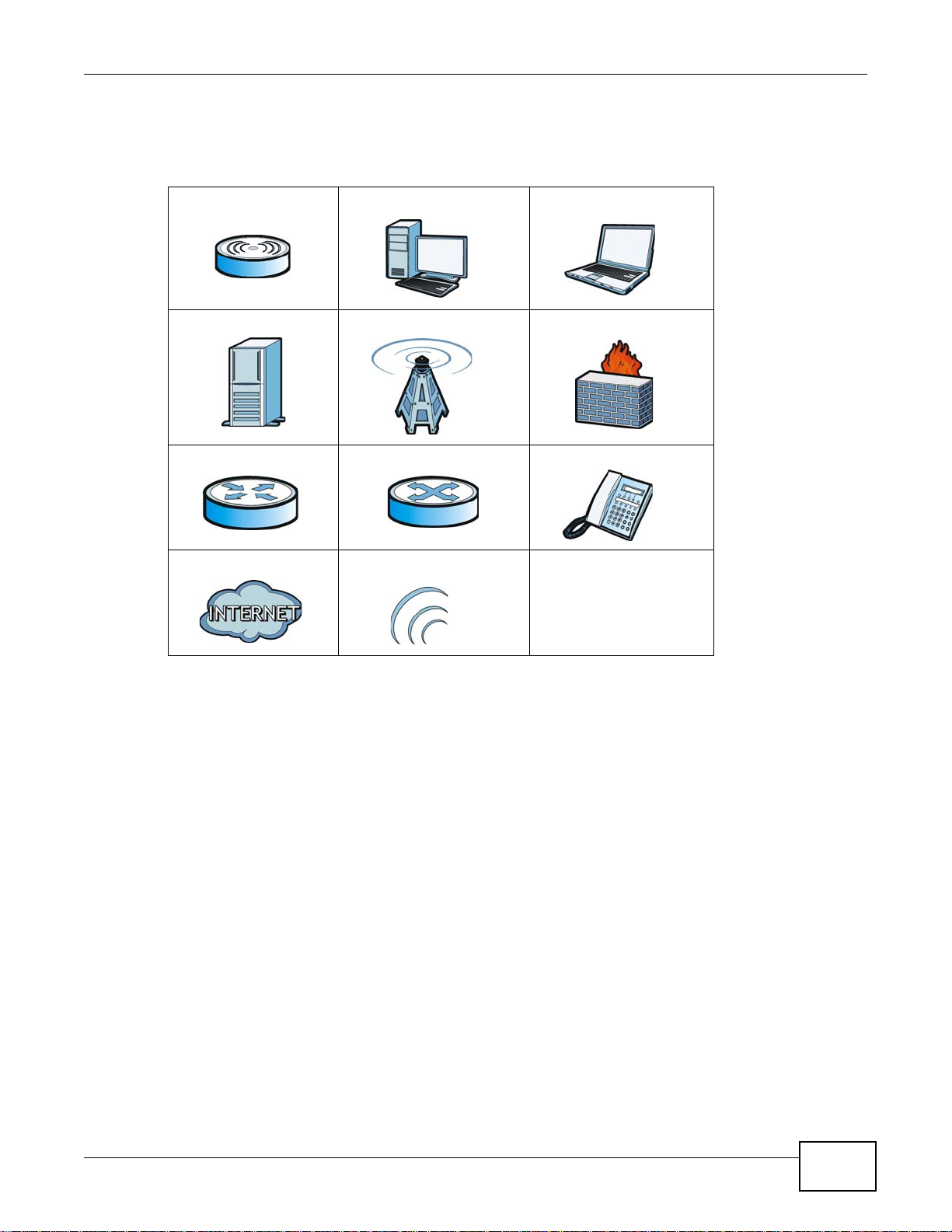
Icons Used in Figures
Figures in this User’s Guide may use the following generic icons. The WiMAX icon is not an exact
representation of your device.
4
WiMAX Device Configuration User’s Guide
Page 5
Document Conventions
Graphics in this book may differ slightly from the product due to differences in operating systems,
operating system versions, or if you installed updated firmware/software for your device. Every
effort has been made to ensure that the information in this manual is accurate.
WiMAX Device Computer Notebook computer
Server Base Station Firewall
Router Switch Telephone
Internet Wireless Signal
WiMAX Device Configuration User’s Guide
5
Page 6

Safety Warnings
• Do NOT use this product near water, for example, in a wet basement or near a swimming pool.
• Do NOT expose your device to dampness, dust or corrosive liquids .
• Do NOT store things on the device.
• Do NOT install, use, or service this device during a thunderstorm. There is a remote risk of electric shock
• Connect ONLY suitable accessories to the device.
• Do NOT open the device or unit. Opening or removing covers can expose you to dangerous high voltage
• ONLY qualified service personnel should service or disassemble this device.
• Make sure to connect the cables to the correct ports.
• Place connecting cables carefully so that no one will step on them or stumble over them.
• Always disconnect all cables from this device before servicing or disassembling.
• Use ONLY an appropriate power adaptor or cord for your device.
• Connect the power adaptor or cord to the right supply voltage (for example, 110V AC in North America or
• Do NOT remove the plug and connect it to a power outlet by itself; always attach the plug to the power
• Do NOT allow anything to rest on the power adaptor or cord and do NOT place the pro duct where an yone can
• Do NOT use the devi ce if the power adaptor or cord is damaged as it might cause electrocution.
• If the power adaptor or cord is damaged, remove it from the power outlet.
• Do NOT attempt to repair the power adaptor or cord. Contact your local vendor to order a new one.
• For indoor devices, do not use the device outside, and make sure all the connections are indoors. There is a
• Do NOT obstruct the devi ce ventilation slots, as insufficient airflow may harm your device.Use only No. 26
• Antenna Warning! This device meets ETSI and FCC certification requirements when using the inc luded
• If you wall mount your device, make sure that no electrical lines, gas or water pipes will be damaged.
• Make sure that the cable system is grounded so as to provide some protection against voltage surges.
Safety Warnings
from lightning.
points or other risks. ONLY qualified service personnel should service or disassemble this device. Please
contact your vendor for further information.
230V AC in Europe).
adaptor first before connecting it to a power outlet.
walk on the power adaptor or cord.
remote risk of electric shock from lightning.
AWG (American Wire Gauge) or larger telecommunication line cord.
antenna(s). Only use the included antenna(s).
Your product is marked with this symbol, which is known as the WEEE mark. WEEE stands for Waste
Electronics and Electrical Equipment. It means that used electrical and electronic products should not
be mixed with general waste. Used electrical and electronic equipment should be treated separately.
6
WiMAX Device Configuration User’s Guide
Page 7

Contents Overview
Contents Overview
User’s Guide ...........................................................................................................................15
Introduction to the Series ...........................................................................................................17
Introduction to the Web Configurator .........................................................................................20
Setup Wizard.............................................................................................................................. 25
Tutorials .....................................................................................................................................35
Technical Reference .............................................................................................................. 61
System Status ............................................................................................................................63
WiMAX .......................................................................................................................................67
Network Setting .......................................................................................................................... 91
Security ....................................................................................................................................125
The VoIP General Screens ......................................................................................................151
The VoIP Account Screens ......................................................................................................157
The VoIP Line Screens ............................................................................................................171
Maintenance .............................................................................................................................175
Troubleshooting .......................................................................................................................197
Product Specifications ..............................................................................................................203
WiMAX Device Configuration User’s Guide
7
Page 8

Contents Overview
8
WiMAX Device Configuration User’s Guide
Page 9

Table of Contents
Table of Contents
About This User's Guide..........................................................................................................3
Document Conventions ...........................................................................................................4
Safety Warnings........................................................................................................................6
Contents Overview ..................................................................................................................7
Table of Contents .....................................................................................................................9
Part I: User’s Guide ................................................................................15
Chapter 1
Introduction to the Series......................................................................................................17
1.1 About Your WiMAX Device ..................................................................................................17
1.1.1 WiMAX Internet Access ..............................................................................................18
1.1.2 Models with Phone Ports ............................................................................................18
1.1.3 Models with WiFi ........................................................................................................19
1.2 Good Habits for Managing the WiMAX Device ....................................................................19
Chapter 2
Introduction to the Web Configurator...................................................................................20
2.1 Overview ..............................................................................................................................20
2.1.1 Accessing the Web Configurator ................................................................................ 20
2.1.2 Saving and Canceling Changes .................................................................................21
2.1.3 Working with Tables ....................................................................................................21
2.2 The Main Screen ..................................................................................................................22
Chapter 3
Setup Wizard........................................................................................................................... 25
3.1 Overview ..............................................................................................................................25
3.1.1 Welcome to the Setup Wizard ....................................................................................25
3.1.2 LAN Settings ...............................................................................................................26
3.1.3 WiMAX Frequency Settings ........................................................................................27
3.1.4 WiMAX Authentication Settings .................................................................................. 28
3.1.5 VoIP Settings ..............................................................................................................30
3.1.6 WLAN Settings ...........................................................................................................32
3.1.7 Setup Complete ..........................................................................................................34
WiMAX Device Configuration User’s Guide
9
Page 10

Table of Contents
Chapter 4
Tutorials................................................................................................................................... 35
4.1 Overview ..............................................................................................................................35
4.2 WiMAX Connection Settings ................................................................................................35
4.3 Setting Up a Small Network for the LAN .............................................................................. 36
4.4 Making a Telephone Call Over the Internet .......................................................................... 38
4.4.1 Configure Your SIP Account .......................................................................................38
4.5 Blocking Web Access from the WiMAX Device ...................................................................40
4.6 Restricting Wireless Access to the WiMAX Device ..............................................................40
4.7 Allowing Internet Users to use Internal Servers ...................................................................42
4.8 Access the WiMAX Device with a Domain Name ................................................................44
4.8.1 Registering a DDNS Account on www.dyndns.org .....................................................45
4.8.2 Configuring DDNS on Your WiMAX Device ................................................................46
4.8.3 Testing the DDNS Setting ...........................................................................................46
4.9 Configuring Static Route for Routing to Another Network ....................................................46
4.10 Remotely Managing Your WiMAX Device ..........................................................................48
4.11 Changing Certificate to Communicate with Other Networks ..............................................49
4.12 Using Virtual Networks ....................................................................................................... 50
4.12.1 Scenario 1 ................................................................................................................51
4.12.2 Scenario 2 ................................................................................................................52
4.12.3 Scenario 3 ................................................................................................................54
4.12.4 Scenario 4 ................................................................................................................56
4.12.5 Scenario 5 ................................................................................................................58
Part II: Technical Reference...................................................................61
Chapter 5
System Status......................................................................................................................... 63
5.1 Overview ..............................................................................................................................63
5.2 System Status ......................................................................................................................63
Chapter 6
WiMAX .....................................................................................................................................67
6.1 Overview ..............................................................................................................................67
6.1.1 What You Need to Know .............................................................................................67
6.2 Connection Settings .............................................................................................................70
6.3 Frequency Settings ..............................................................................................................72
6.4 Authentication Settings ........................................................................................................74
6.5 Channel Plan Settings ..........................................................................................................77
6.6 CAPL Settings ......................................................................................................................79
6.6.1 CAPL Settings: Add ....................................................................................................80
10
WiMAX Device Configuration User’s Guide
Page 11

Table of Contents
6.7 RAPL Settings ......................................................................................................................81
6.8 Home NSP Settings .............................................................................................................82
6.9 Connect ................................................................................................................................83
6.10 Wide Scan ..........................................................................................................................85
6.11 Link Status ..........................................................................................................................87
6.12 Link Statistics .....................................................................................................................88
6.13 Connection Info ..................................................................................................................89
6.14 Service Flow .......................................................................................................................89
Chapter 7
Network Setting ......................................................................................................................91
7.1 Overview ..............................................................................................................................91
7.1.1 What You Need to Know .............................................................................................91
7.2 WAN .....................................................................................................................................94
7.3 PPPoE ..................................................................................................................................96
7.4 GRE .....................................................................................................................................97
7.5 EtherIP ................................................................................................................................. 98
7.6 IP ..........................................................................................................................................98
7.7 DHCP ...................................................................................................................................99
7.8 WLAN .................................................................................................................................100
7.9 WPS ...................................................................................................................................102
7.10 MAC Address Filter ..........................................................................................................103
7.11 Static Route ......................................................................................................................104
7.12 Static Route Add ..............................................................................................................104
7.13 RIP ................................................................................................................................... 105
7.14 Port Forwarding ................................................................................................................107
7.14.1 Port Forwarding Wizard .......................................................................................... 108
7.15 Port Trigger ......................................................................................................................108
7.15.1 Port Trigger Wizard ................................................................................................. 110
7.15.2 Trigger Port Forwarding Example ........................................................................... 111
7.16 DMZ ................................................................................................................................. 111
7.17 ALG .................................................................................................................................. 112
7.18 QoS .................................................................................................................................. 113
7.19 UPnP ................................................................................................................................ 113
7.19.1 Installing UPnP in Windows XP .............................................................................. 114
7.19.2 Web Configurator Easy Access .............................................................................. 118
7.20 VLAN ................................................................................................................................ 119
7.21 DDNS ...............................................................................................................................121
7.22 IGMP Proxy ......................................................................................................................123
7.23 Content Filter ....................................................................................................................123
Chapter 8
Security..................................................................................................................................125
WiMAX Device Configuration User’s Guide
11
Page 12

Table of Contents
8.1 Overview ............................................................................................................................125
8.1.1 What You Need to Know ...........................................................................................125
8.2 IP Filter ...............................................................................................................................125
8.3 MAC Filter ..........................................................................................................................126
8.4 DDOS .................................................................................................................................127
8.5 PPTP VPN Server ..............................................................................................................129
8.6 PPTP VPN Client ...............................................................................................................130
8.7 PPTP VPN Client: Add .......................................................................................................131
8.8 L2TP VPN Server ...............................................................................................................133
8.9 L2TP VPN Client ................................................................................................................135
8.10 L2TP VPN Client: Add ......................................................................................................135
8.11 IPSec VPN .......................................................................................................................137
8.11.1 IPSec VPN: Add ......................................................................................................139
8.12 Technical Reference .........................................................................................................144
8.12.1 IPSec Architecture ..................................................................................................144
8.12.2 Encapsulation .........................................................................................................145
8.12.3 IKE Phases ............................................................................................................146
8.12.4 Negotiation Mode ...................................................................................................147
8.12.5 IPSec and NAT .......................................................................................................147
8.12.6 VPN, NAT, and NAT Traversal ................................................................................148
8.12.7 ID Type and Content ...............................................................................................148
8.12.8 Pre-Shared Key ......................................................................................................150
8.12.9 Diffie-Hellman (DH) Key Groups .............................................................................150
Chapter 9
The VoIP General Screens ...................................................................................................151
9.1 VoIP Overview ....................................................................................................................151
9.1.1 What You Need to Know ...........................................................................................151
9.1.2 Before you Begin ......................................................................................................152
9.2 Media .................................................................................................................................153
9.3 QoS ....................................................................................................................................154
9.4 SIP Settings .......................................................................................................................155
9.5 Speed Dial ..........................................................................................................................155
9.6 Technical Reference ...........................................................................................................156
9.6.1 DSCP and Per-Hop Behavior ...................................................................................156
Chapter 10
The VoIP Account Screens ..................................................................................................157
10.1 Overview ..........................................................................................................................157
10.1.1 What You Need to Know .........................................................................................157
10.2 Status ...............................................................................................................................160
10.3 Server ...............................................................................................................................161
10.4 SIP ...................................................................................................................................163
12
WiMAX Device Configuration User’s Guide
Page 13

Table of Contents
10.5 Feature .............................................................................................................................165
10.6 Dialing ..............................................................................................................................166
10.7 FAX ..................................................................................................................................167
10.8 Technical Reference .........................................................................................................167
10.8.1 SIP Call Progression with Session Timer ...............................................................167
10.8.2 SIP Client Server ....................................................................................................170
Chapter 11
The VoIP Line Screens .........................................................................................................171
11.1 Overview ..........................................................................................................................171
11.1.1 What You Need to Know .........................................................................................171
11.2 Phone ............................................................................................................................... 172
11.3 Voice ................................................................................................................................. 172
11.4 Region .............................................................................................................................. 173
Chapter 12
Maintenance.......................................................................................................................... 175
12.1 Overview ..........................................................................................................................175
12.1.1 What You Need to Know .........................................................................................175
12.2 Password .........................................................................................................................180
12.3 HTTP ................................................................................................................................181
12.4 Telnet ................................................................................................................................181
12.5 SSH ..................................................................................................................................182
12.6 SNMP ...............................................................................................................................183
12.7 CWMP ..............................................................................................................................183
12.8 OMA-DM ..........................................................................................................................185
12.9 Date/Time .........................................................................................................................187
12.10 Time Zone ......................................................................................................................187
12.11 Upgrade File ................................................................................................................... 188
12.11.1 The Firmware Upload Process .............................................................................189
12.12 Upgrade Link ..................................................................................................................189
12.13 CWMP Upgrade .............................................................................................................189
12.14 Backup/Restore ..............................................................................................................190
12.15 Restore ...........................................................................................................................190
12.15.1 The Restore Configuration Process .....................................................................191
12.16 Factory Defaults .............................................................................................................191
12.17 Log Setting .....................................................................................................................192
12.18 Log Display ....................................................................................................................192
12.19 Network Test ..................................................................................................................193
12.20 Traceroute ......................................................................................................................194
12.21 About ..............................................................................................................................194
12.22 Reboot ............................................................................................................................195
WiMAX Device Configuration User’s Guide
13
Page 14

Table of Contents
Chapter 13
Troubleshooting....................................................................................................................197
13.1 Power, Hardware Connections, and LEDs .......................................................................197
13.2 WiMAX Device Access and Login ....................................................................................198
13.3 Internet Access ................................................................................................................199
13.4 Wireless Internet Access (for Models with WiFi) ..............................................................201
13.5 Phone Calls and VoIP (for Models with Phone Ports) ......................................................201
13.6 Reset the WiMAX Device to Its Factory Defaults .............................................................202
13.6.1 Pop-up Windows, JavaScript and Java Permissions .............................................202
Chapter 14
Product Specifications.........................................................................................................203
Appendix A WiMAX Security ............................................................................................... 207
Appendix B Importing Certificates ....................................................................................... 211
Appendix C Common Services............................................................................................237
Appendix D Open Software Announcements ...................................................................... 241
Appendix E Legal Information..............................................................................................277
Index ......................................................................................................................................285
14
WiMAX Device Configuration User’s Guide
Page 15

PART I
User’s Guide
15
Page 16

16
Page 17
Introduction to the Series
1.1 About Your WiMAX Device
The WiMAX Device allows you to access the Internet by connecting to a WiMAX wireless network.
For some models, you can use a traditional analog telephone to make Internet calls using the
WiMAX Device’s Voice over IP (VoIP) communication capabilities.
Additionally, The web browser-based Graphical User Interface (GUI), also known as the web
configurator, provides easy management of the device and its features.
Please refer to the following description of the product name format.
• Models starting with “2” (for example MAX208M2W) denote an indoor CPE device; models
starting with “3” (for example MAX318M2W) denote an outdoor CPE device.
• Models with the second number as “0” (for example MAX208M2W) denote that its frequency
band is 2.5GHz ~ 2.7GHz; models with the second number as “1” (for example MAX218M2W)
denote that its frequency band is 3.4GHz ~ 3.6GHz.
• The number after the letter “M” denote the number of VoIP ports that the device has. For
example, MAX208M2W has 2 VoIP ports; MAX218M has no VoIP port.
• Models ending with “W” (for example MAX20 8 M 2W) denote WiFi functionality, including 802.11n
mode.
CHAPTER 1
See the following table for the main features for each specific model:
Table 1 Main Features
FEATURE /
MODEL
MAX208M
MAX218M
MAX208M2W
MAX218M2W
MAX218M1W
MAX218MW
MAX318M2W
MAX308M
MAX318M
FREQUENCY
BAND
2.5 ~ 2.7 GHz N/A N/A
3.4 ~ 3.6 GHz N/A N/A
2.5 ~ 2.7 GHz 2
3.4 ~ 3.6 GHz 2
3.4 ~ 3.6 GHz 1
3.4 ~ 3.6 GHz N/A
3.4 ~ 3.6 GHz 2
2.5 ~ 2.7 GHz N/A N/A
3.4 ~ 3.6 GHz N/A N/A
NUMBER OF
PHONE
PORTS
WIFI
FUNCTION
INDOOR
DEVICE
OUTDOOR
DEVICE
WiMAX Device Configuration User’s Guide 17
Page 18
Chapter 1 Introduction to the Series
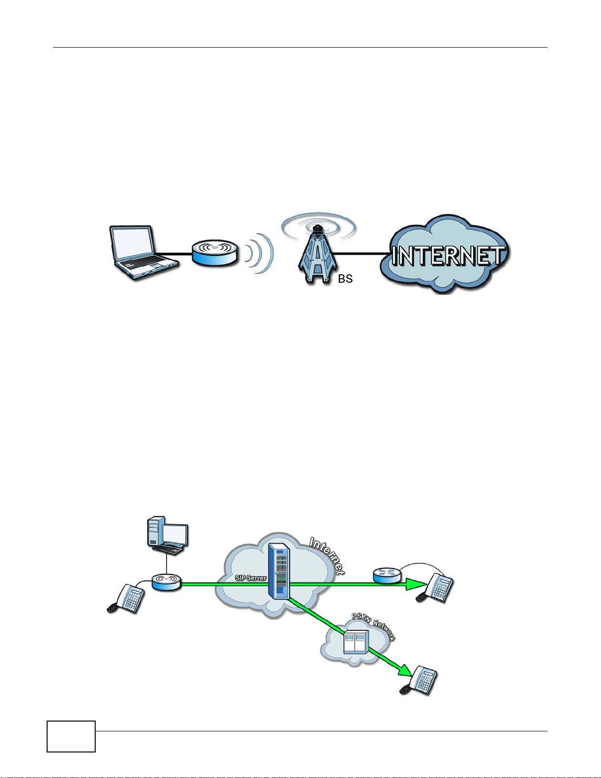
1.1.1 WiMAX Internet Access
Connect your computer or network to the WiMAX Device for WiMAX Internet access. See the Quick
Start Guide for instructions on hardware connection.
In a wireless metropolitan area network (MAN), the WiMAX Device connects to a WiMAX base
station (BS) for Internet access.
The following diagram shows a notebook computer equipped with the WiMAX Device connecting to
the Internet through a WiMAX base station (marked BS).
Figure 1 Mobile Station and Base Station
When the firewall is on, all incoming traffic from the Internet to your network is blocked unless it is
initiated from your network.
Use content filtering to block access to web sites with URLs containing keywords that you sp ec ify.
You can define time periods and days during which content filtering is enabled and include or
exclude particular computers on your network from content filtering. For example, you could block
access to certain web sites for the kids.
1.1.2 Models with Phone Ports
For models with phone ports, you can use the WiMAX Device to make and receive Voice over
Internet Phone (VoIP) telephone calls:
• Calls via a VoIP service provider - The WiMAX Device sends your call to a VoIP service provider’s
SIP server which forwards your calls to either VoIP or PSTN phones.
Figure 2 Calls via VoIP Service Provider
18
WiMAX Device Configuration User’s Guide
Page 19
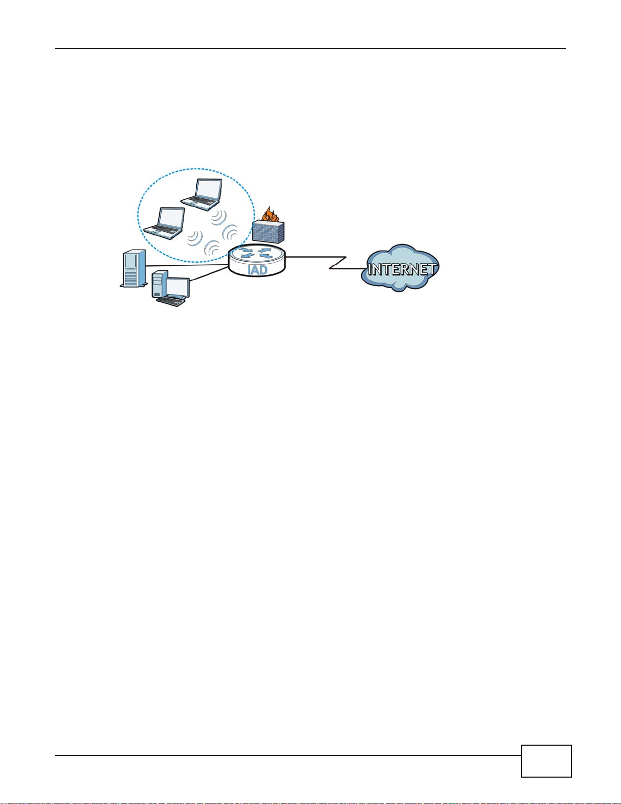
1.1.3 Models with WiFi
LAN
WLAN
WAN
For WiFi models, IEEE 802.11b/g/n compliant clients can wirelessly connect to the WiMAX Device to
access network resources. You can set up a wireless network with WPS (WiFi Protected Setup) or
manually add a client to your wireless network.
Figure 3 WiFi Connection Application
Chapter 1 Introduction to the Series
1.2 Good Habits for Managing the WiMAX Device
Do the following things regularly to make the WiMAX Device more secure and to manage the
WiMAX Device more effectively.
• Change the password. Use a password that’s not easy to guess and that consists of different
types of characters, such as numbers and letters.
• Write down the password and put it in a safe place.
• Back up the configuration (and make sure you know how to restore it). Restoring an earlier
working configuration may be useful if the WiMAX Device becomes unstable or even crashes. If
you forget your password, you will have to reset the WiMAX Device to its factory default settings.
If you backed up an earlier configuration file, you would not have to totally re-configure the
WiMAX Device. You could simply restore your last configuration.
WiMAX Device Configuration User’s Guide
19
Page 20
Introduction to the Web Configurator
2.1 Overview
The Web Configurator is an HTML-based management interface that allows easy device set up and
management via any web browser that supports: HTML 4.0, CSS 2.0, and JavaScript 1.5, and
higher. The recommended screen resolution for using the web configurator is 1024 by 768 pixels
and 16-bit color, or higher.
In order to use the Web Configurator you need to allow:
• Web browser pop-up windows from your device. Web pop-up blocking is enabled by default in
many operating systems and web browsers.
• JavaScript (enabled by default in most web browsers).
• Java permissions (enabled by default in most web browsers).
CHAPTER 2
See the Appendix C on page 233 for more information on configuring your web browser.
2.1.1 Accessing the Web Configurator
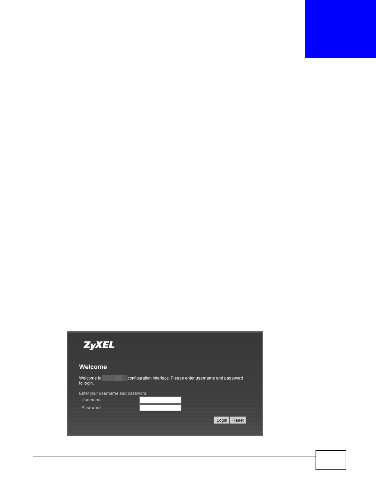
1 Make sure your WiMAX Device hardware is properly connected (refer to the Quick Start Guide for
more information).
2 Launch your web browser.
3 Enter 192.168.1.1192.168.1.1" as the URL.
4 A login screen displays. Enter the default Username (admin) and Password (1234), then click
Login.
Figure 4 Login screen
WiMAX Device Configuration User’s Guide 20
Page 21
Note: For security reasons, the WiMAX Device automatically logs you out if you do not
use the Web Configurator for five minutes. If this happens, log in again.
2.1.2 Saving and Canceling Changes
All screens to which you can make configuration changes must be saved before those changes can
go into effect. If you make a mistake while configuring the WiMAX Device, you can cancel those
changes and start over.
Figure 5 Saving and Canceling Changes
This screen contains the following fields:
Chapter 2 Introduction to the Web Configurator
Table 2 Saving and Canceling Changes
LABEL DESCRIPTION
Save Click this to save your changes.
Cancel Click this to restore the settings on this page to their last saved values.
Note: If you make changes to a page but do not save before switching to another page or
exiting the Web Configurator, those changes are discarded.
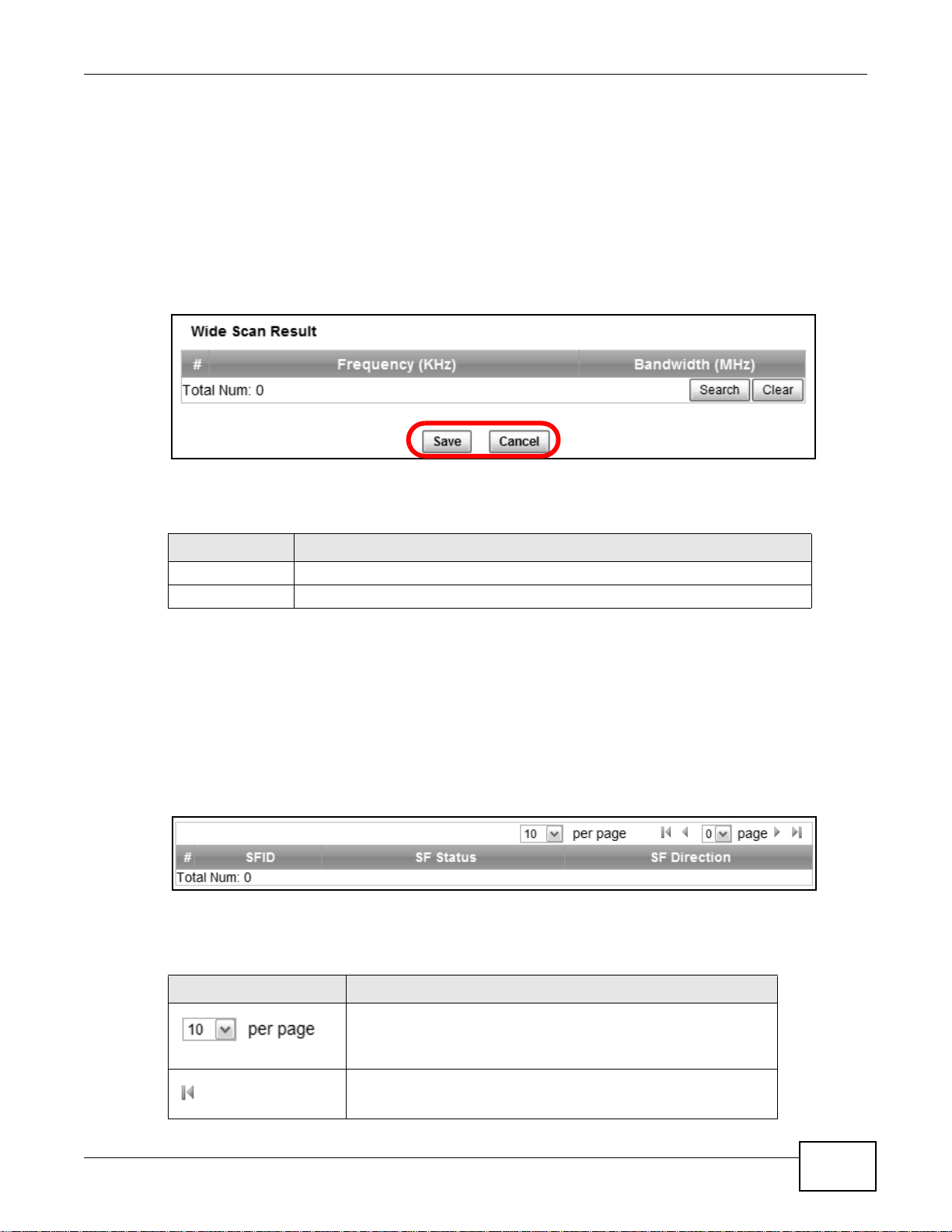
2.1.3 Working with Tables
Many screens in the WiMAX Device contain tables to provide information or additional configuration
options.
Figure 6 Tables Example
This screen contains the following fields:
Table 3 Saving and Canceling Changes
LABEL DESCRIPTION
Items per Page
This displays the number of items displayed per table page. Use
the menu to change this value.
First Page
Click this to go to the first page in the table.
WiMAX Device Configuration User’s Guide
21
Page 22
Chapter 2 Introduction to the Web Configurator
Table 3 Saving and Canceling Changes (continued)
LABEL DESCRIPTION
Previous Page
Click this to go to the previous page in the table.
Page Indicator / Jump to Page
This indicates which page is currently displayed in the table. Use
the menu to jump to another page. You can only jump to other
pages if those pages exist.
Next Page
Click this to go to the previous page in the table.
Last Page
Click this to go to the last page in the table.
# This indicates an item’s position in the table. It has no bearing on
that item’s importance or lack there of.
Total Num This indicates the total number of items in the table, including
items on pages that are not visible.
2.2 The Main Screen
When you first log into the Web Configurator, the Main screen appears. Here you can view a
summary of your WiMAX Device’s connection status. This is also the default “home” page for the
Web Configurator and it contains conveniently-placed shortcuts to all of the other screens.
Note: Some features in the Web Configurator may not be available depending on your
model and firmware version and/or configuration.
22
WiMAX Device Configuration User’s Guide
Page 23
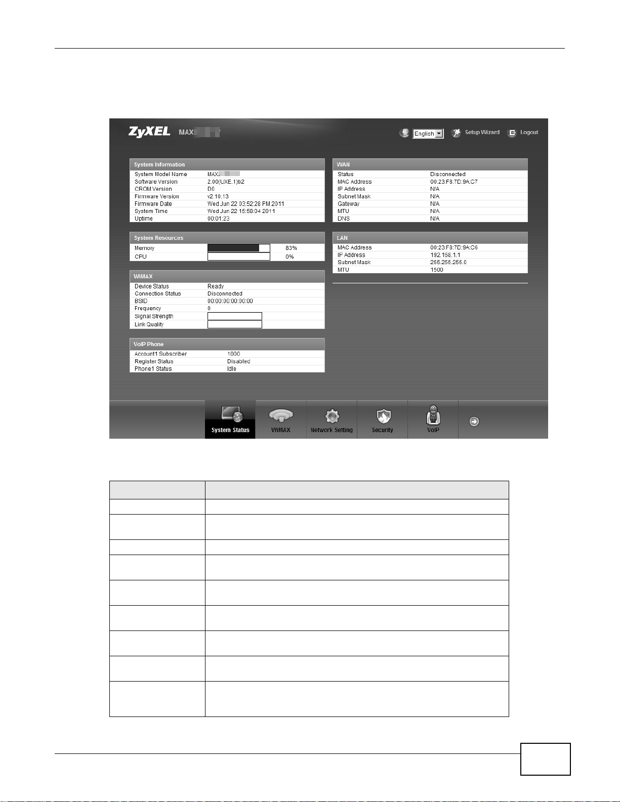
Chapter 2 Introduction to the Web Configurator
Note: The available menus and screens vary depending on the type of account (admin or
guest) you use for login.
Figure 7 Main Screen
The following table describes the menus in this screen.
Table 4 Main > Menu
MENU DESCRIPTION
Language Use this menu to select the Web Configurator’s language.
Setup Wizard Click this to open the Setup Wizard, where you can configure the most
essential settings for your WiMAX Device to work.
Logout Click this to log out of the Web Configurator.
System Status Click this to open the Main screen, which shows your WiMAX Device
status and other information.
WiMAX Click this to open the WiMAX menu, which gives you options for
configuring your WiMAX settings.
Network Setting Click this to open the Network menu, which gives you options for
Security Click this to open the Security menu, which gives you options for
VoIP Click this icon to open the VoIP menu, which gives you options on how to
Maintenance Click this to open the Maintenance menu, which gives you options for
configuring your WAN/LAN/WiFi network settings.
configuring your firewall and security settings.
make telephone calls over the Internet via the WiMAX Device.
maintaining your WiMAX Device and performing basic network
connectivity tests.
WiMAX Device Configuration User’s Guide
23
Page 24

Chapter 2 Introduction to the Web Configurator
24
WiMAX Device Configuration User’s Guide
Page 25
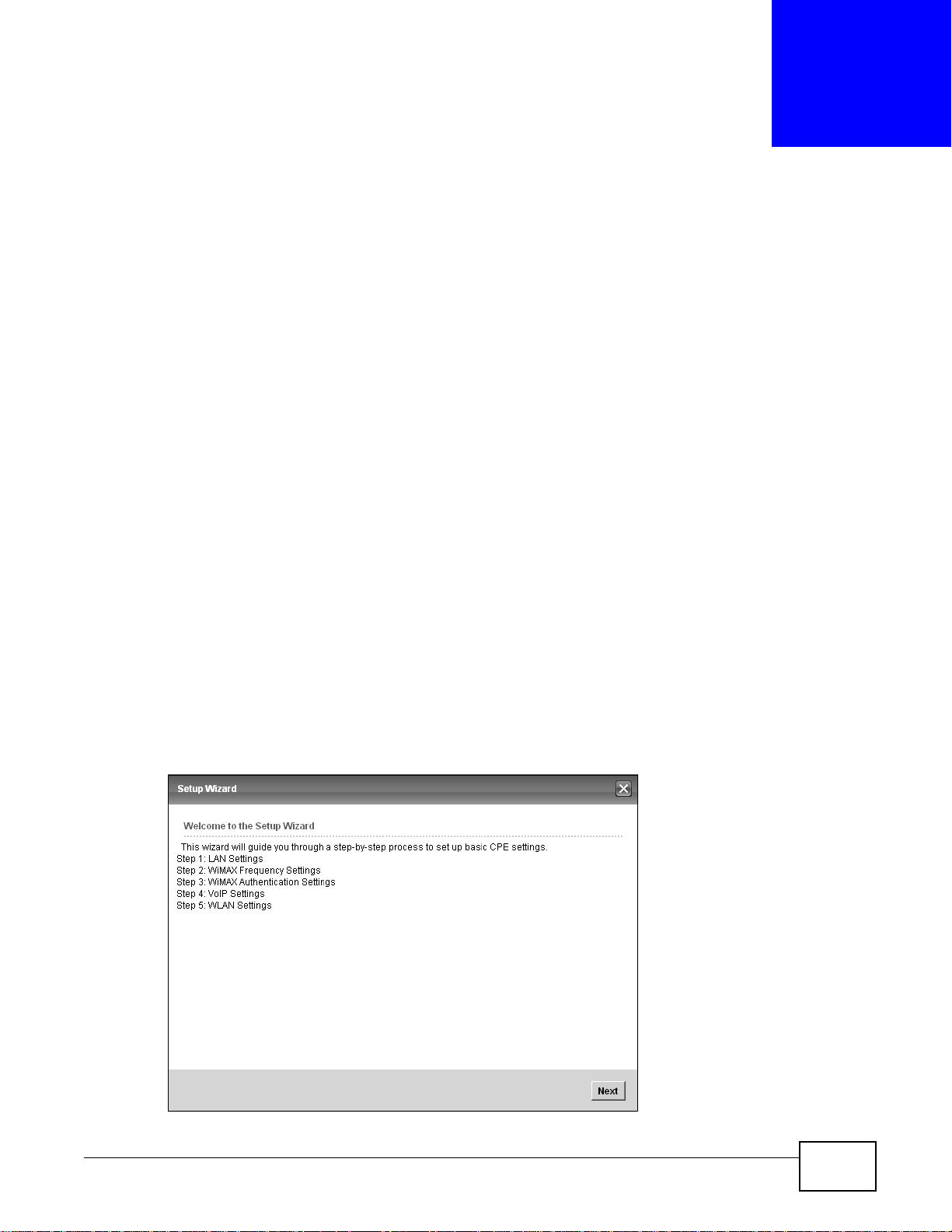
3.1 Overview
This chapter provides information on the Setup Wizard. The wizard guides you through several
steps for configuring your network settings.
3.1.1 Welcome to the Setup Wizard
This screen provides a quick summary of the configuration tasks the wizard helps you to perform.
They are:
1 Set up your Local Area Network (LAN) options, which determine how the devices in your home or
office connect to the WiMAX Device.
CHAPTER 3
Setup Wizard
2 Set up your WiMAX Device’s broadcast frequency, which is the radio channel it uses to communicate
with the ISP’s base station.
3 Set up your WiMAX Device’s login options, which are used to connect your LAN to the ISP’ s network
and verify your account.
4 For models with VoIP feature, set up your WiMAX Device’s VoIP Settings, which will allow you to
make calls over the IInternet.
5 For models with WiFi feature, set up your WiMAX Device’s wireless LAN so that other devices, such
as a laptop or a smartphone, can connect wirelessly to the Internet using the WiMAX Device.
Figure 8 Setup Wizard > Welcome
WiMAX Device Configuration User’s Guide 25
Page 26
Chapter 3 Setup Wizard
3.1.2 LAN Settings
The LAN Settings screen allows you to configure your local network options.
Figure 9 Setup Wizard > LAN Settings
The following table describes the labels in this screen.
Table 5 Setup Wizard > LAN Settings
LABEL DESCRIPTION
LAN TCP/IP
IP Address Enter the IP address of the WiMAX Device on the LAN.
Note: This field is the IP address you use to access the WiMAX Device on the LAN. If
the web configurator is running on a computer on the LAN, you lose access to
it as soon as you change this field. You can access the web configurator again
by typing the new IP address in the browser.
IP Subnet
Mask
DHCP Server
Enable Select this if you want the WiMAX Device to be the DHCP server on the LAN. As a
Start IP Enter the IP address from which the WiMAX Device begins allocating IP addresses.
End IP Enter the IP address at which the WiMAX Device stops allocating IP addresses.
Lease
Time
DNS Server assigned by DHCP Server
First DNS
Server
Enter the subnet mask of the LAN.
DHCP server, the WiMAX Device a ssigns IP addresses to DHCP clients on the LAN
and provides the subnet mask and DNS server information.
Enter the duration in minutes before the device requests a new IP address from the
DHCP server.
Specify the first IP address of three DNS servers that the network can use. The
WiMAX Device provides these IP addresses to DHCP clients.
26
WiMAX Device Configuration User’s Guide
Page 27
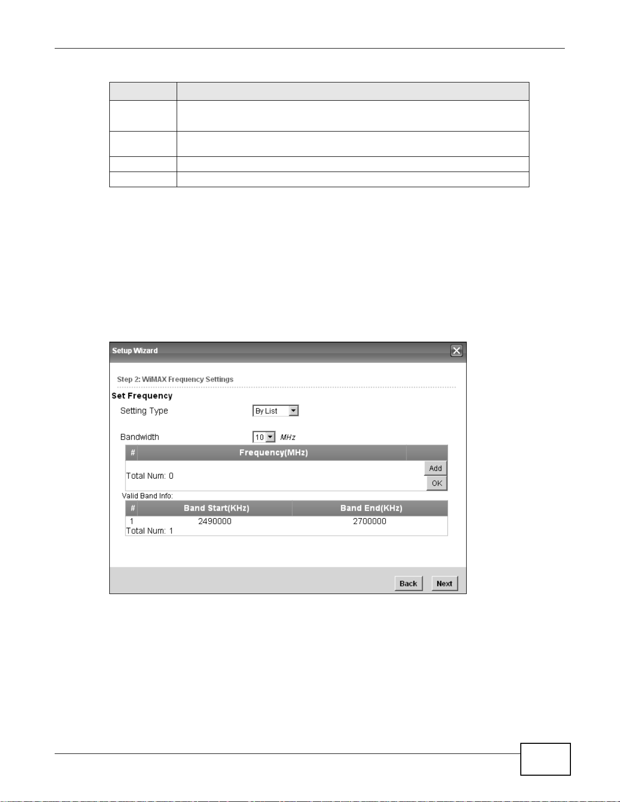
Table 5 Setup Wizard > LAN Settings (continued)
LABEL DESCRIPTION
Second
DNS
Server
Third DNS
Server
Back Click to display the previous screen.
Next Click to proceed to the next screen.
Specify the second IP address of three DNS servers that the network can use. The
WiMAX Device provides these IP addresses to DHCP clients.
Specify the third IP address of three DNS servers that the network can use. The
WiMAX Device provides these IP addresses to DHCP clients.
3.1.3 WiMAX Frequency Settings
The WiMAX Frequency Settings screen allows you to configure the broadcast radio frequency used
by the WiMAX Device.
Note: The frequency band varies for different models. See Section 1.1 on page 17 for
more information.
Note: These settings should be provided by your ISP.
Chapter 3 Setup Wizard
Figure 10 Setup Wizard > WiMAX Frequency Settings
WiMAX Device Configuration User’s Guide
27
Page 28

Chapter 3 Setup Wizard
The following table describes the labels in this screen.
Table 6 Setup Wizard > WiMAX Frequency Setting s
LABEL DESCRIPTION
Setting Type Select the WiMAX frequency setting type from the list.
Step Enter the increments in MHz by which to increase the frequen cy range.
Start Frequency Enter the frequency value at the beginning of the frequency range to use.
End Frequency Enter the frequency value at the end of the frequency range to use.
Bandwidth Set the frequency bandwidth in MHz that this WiMAX Device uses.
# This is an index number for enumeration purposes only.
Frequency (MHz) Displays the frequency MHz for the item in the list.
Total Num Displays the total number of items in the list.
Delete Click this to remove an item from the list.
Add Click this to add an item to the list.
OK Click this to save an newly added item to the list.
# This is an index number for enumeration purposes only.
Band Start (KHz) Indicates the beginning of the frequency band in KHz.
Band End (KHz) Indicates the end of the frequency band in KHz.
Total Num Displays the total number of items in the list.
Back Click to display the previous screen.
Next Click to proceed to the next screen.
• By Range - Select this to set up the frequency based on a range of
MHz.
• By List - Select this to set up the frequency on an individual MHz basis.
You can add multiple MHz values to the list.
Note: This field only appears when you select By Range under Setting Type.
The frequency is increased in increments equal to the Step value until the
End Frequency is reached, at which time the cycle starts over with the
Start Frequency.
Note: This field only appears when you select By Range under Setting Type.
Note: This field only appears when you select By Range under Setting Type.
3.1.4 WiMAX Authentication Settings
The WiMAX Authentication Settings screen allows you to configure how your WiMAX Device logs
into the service provider’s network.
Note: These settings should be provided by your ISP.
Note: The EAP supplicant settings on this screen vary depending on the authentication
mode your select.
28
WiMAX Device Configuration User’s Guide
Page 29
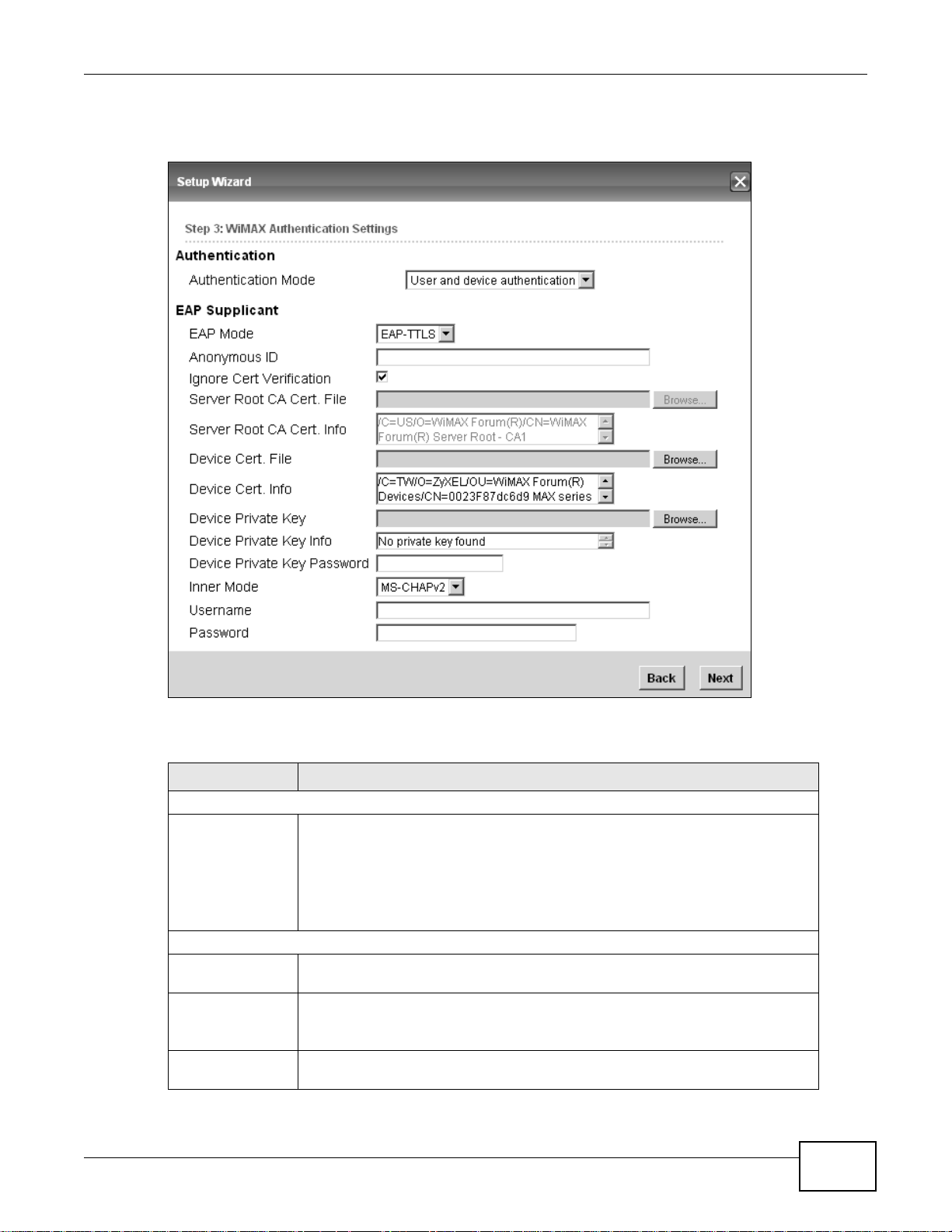
Figure 11 Setup Wizard > WiMAX Authentication Settings
Chapter 3 Setup Wizard
The following table describes the labels in this screen.
Table 7 Setup Wizard > WiMAX Authentication Settings
LABEL DESCRIPTION
Authentication
Authentication
Mode
EAP Supplication
EAP Mode Select an EAP authentication mode. See Table 14 on page 76 if you need more
Anonymous Id Enter your anonymous ID.
Select a WiMAX authentication mode for authentication networ k sessions with the
ISP. Options are:
• No authentic a tion
• User authentication
• Device authentication
• User and Device authentication
information.
Note: Some modes may not require this.
Ignore Cert
Verification
Select this to ignore base station certification verification when a certificate is
received during EAP-TLS or EA P-TTLS.
WiMAX Device Configuration User’s Guide
29
Page 30

Chapter 3 Setup Wizard
Table 7 Setup Wizard > WiMAX Authentication Settings (continued)
LABEL DESCRIPTION
Server Root CA
Cert. File
Server Root CA
Cert. Info
Device Cert.
File
Device Cert.
Info.
Device Private
Key
Device Private
Key
Info
Device Private
Key Password
Inner Mode Select an inner authentication mode (MS-CHAP, MS-CHAPV2, CHAP, MD5, PAP.
Username Enter your authentication username.
Password Enter your authentication password.
Back Click to display the previous screen.
Next Click to proc eed to the next screen.
Browse for and choose a server root certificate file, if required.
This field displays information about the assigned server root certificate.
Browse for and choose a device certificate file, if required.
This field displays information about the assigned device certificate.
Browse for and choose a device private key, if required.
This field displays information about the assigned device private key.
Enter the device private key, if required.
See Table 14 on page 76 if you need more information.
3.1.5 VoIP Settings
For models with V oIP feature, you can configure your VoIP settings in the Setup Wizard. The VoIP
Settings screen allows you to configure how your WiMAX Device connects to the VoIP service
provider’s network and makes calls over the Internet.
30
WiMAX Device Configuration User’s Guide
Page 31

Note: This settings should be provided by your VoIP service provider.
Figure 12 Setup Wizard > VoIP Settings
Chapter 3 Setup Wizard
The following table describes the labels in this screen.
Table 8 Setup Wizard > VoIP Settings
LABEL DESCRIPTION
Line 1/2 SIP Account - Configure this section to use the PHONE 1 and/or PHONE 2 port.
Enable Select this to activate the SIP account.
SIP Server Enter the IP address or domain name of the SIP server.
Port Number Enter the SIP server’s listening port number.
Subscriber Number Enter your SIP number. In the full SIP URI, this is the part before the @ symbol.
Display Name Enter the name that appears on the other party’s device if they have Caller ID
Authentication
Name
Password Type the SIP password associated with this account.
Back Click to display the previous screen.
Next Click to proceed to the next screen.
enabled.
T ype the SIP user name associated with this account for authentication to the SIP
server.
WiMAX Device Configuration User’s Guide
31
Page 32

Chapter 3 Setup Wizard
3.1.6 WLAN Settings
For models with WiFi wireless feature, you can con figure your WLAN settings in the Setup Wizard.
The WLAN Settings screen lets you set up how other devices connect to the Internet wirelessly
using the WiMAX Device.
Figure 13 Setup Wizard > WLAN Settings
32
Figure 14 Setup Wizard > WLAN Settings > Encryption Type: WPA Personal
The following table describes the labels in this screen.
Table 9 Setup Wizard > WLAN Settings
LABEL DESCRIPTION
Wifi Settings
Enable WLAN Select this box to enable the wireless service and allow other wireless clients to
connect to the Internet using the WiMAX Device.
WiMAX Device Configuration User’s Guide
Page 33

Chapter 3 Setup Wizard
Table 9 Setup Wizard > WLAN Settings (continued)
LABEL DESCRIPTION
WLAN Mode Select the mode that the WiMAX Device will be using to communicate: 802.11
B/G mixed, 802.11 B only, 802.11 G only, 802.11 N only, or 802.11 B/G/
N mixed.
WLAN Channel Select one channel from 1 to 13 for wireless communications with the wireless
SSID Settings
WLAN SSID This field displays the name of the wireless network associated with the WiMAX
Hide SSID Select this option if you wish to keep the name of the wireless network hidden.
Encryption Type Select the type of encryption that t he network will be using: None, WEP, or
SSID WEP Settings
stations.
Device.
WPA Personal.
Note: You will only see this options if you selected WEP as the Encryption Type.
Authentication
Method
WEP Encryption
Length
Key 1 - 4 Pick one of four available keys. The key can be in either Hexagecimal (HEX) or
Select the type of authentication used to join the network: Open System or
Shared Key.
Select the length of the encryption key: 64-bit or 128-bit.
ASCII format.
Type the key using any letters and numbers. The field is case sensitive and the
length must match the length picked in the step above (64-bit or 128-bit). A
warning message will appear if you fail to do this.
SSID WPA Settings
Note: You will only see this options if you selected WPA Personal as the Encryption Type.
WPA Mode Select either WPA, WPA2 or Auto (WPA or WPA2).
Cipher Type Select the type of authentication that you wish to use for your network: TKIP,
Pre Shared Key Type the pre-shared key or PSK previously shared between the two parties.
AES or TKIP and AES. AES is more secure.
WiMAX Device Configuration User’s Guide
33
Page 34

Chapter 3 Setup Wizard
3.1.7 Setup Complete
Click Save to save the Setup Wizard settings and close it.
Figure 15 Setup Wizard > Setup Complete
Launch your web browser and navigate to your favorite website. If everything was configured
properly, the web page should display. You can now surf the Internet!
Refer to the rest of this guide for more detailed information on the complete range of WiMAX Device
features available in the more advanced web configurator.
Note: If you cannot access the Internet, open the web configurator again to confirm that
the Internet settings you configured in the Wizard Setup are correct.
34
WiMAX Device Configuration User’s Guide
Page 35

4.1 Overview
Run the Setup Wizard for the basic setup of your WiMAX Device. This chapter shows you how to
configure some of the advanced settings WiMAX Device’s features.
Note: Be sure to read Introduction to the Web Configurator on page 20 before working
through the tutorials presented here. For field descriptions for individual screens,
see the related technical reference in this User's Guide.
This chapter includes the following configuration examples:
• WiMAX Connection Settings on page 35
• Setting Up a Small Network for the LAN on page 36
• Making a Telephone Call Over the Internet on page 38
• Blocking Web Access from the WiMAX Device on page 40
• Restricting Wireless Access to the WiMAX Device on page 40
• Allowing Internet Users to use Internal Servers, see page 42
• Access the WiMAX Device with a Domain Name, see page 44
• Configuring Static Route for Routing to Another Network, see page 46
• Remotely Managing Your WiMAX Device on page 48
• Changing Certificate to Communicate with Other Networks on page 49
• Using Virtual Networks on page 50
CHAPTER 4
Tutorials
4.2 WiMAX Connection Settings
This tutorial provides you with pointers for configuring the WiMAX Device to connect to an ISP.
1 Connect the WiMAX Device to the ISP’s nearest base station. See Section 6.2 on page 70.
2 Configure the WiMAX Device’s broadcast frequency. Section 6.3 on page 72.
3 Configure the WiMAX Device to connect securely to the ISP’s authentication servers. See Section
6.4 on page 74.
4 Check the WiMAX Device’s connection status to ensure everything is working properly. See Section
6.11 on page 87.
WiMAX Device Configuration User’s Guide 35
Page 36

Chapter 4 Tutorials
4.3 Setting Up a Small Network for the LAN
This tutorial shows you how to set up a small network in your office or home.
Goal: Connect three computers to your WiMAX Device to form a small network.
Required: The following table provides a summary of the information you will need to complete
the tasks in this tutorial.
INFORMATION VALUE SEE ALSO
LAN IP Address 192.168.100.1 Chapter 7 on page 98
Starting IP Address 192.168.100.10 Chapter 7 on page 99
Ending IP Address 192.168.100.30
DNS Servers From ISP
1 In the Web Configurator, open the Network Setting > LAN screen and set the IP Address to
192.168.100.1. Use the default IP Subnet Mask of 255.255.255.0. Click Save.
2 Manually change the IP address of your computer that your are using to 192.168.100.x (for
example, 192.168.100.5) and keep the subnet set to 255.255.255.0.
3 Type http://192.168.100.1
in your browser after the WiMAX Device finishes starting up completely.
36
WiMAX Device Configuration User’s Guide
Page 37

Chapter 4 Tutorials
4 Log into the Web Configurator and open the Network Setting > LAN > DHCP screen.
5 Select Server for the DHCP mode, then enter 192.168.100.10 and 192.168.100.30 as your DHCP
starting and ending IP addresses.
6 Leave the other settings as their defaults and click Save.
7 Next, go to the Network Setting > WAN screen and select NAT in the Operation Mode field.
Click Save.
8 Connect your computers to the WiMAX Device’s Ethernet ports and you’re all set!
Note: You may need to configure the computers on your LAN to automatically obtain IP
addresses. For information on how to do this, see Appendix B on page 209.
WiMAX Device Configuration User’s Guide
37
Page 38

Chapter 4 Tutorials
Once your network is configured and hooked up, you will want to connect it to the Internet next. T o
do this, just run the Internet Connection Wizard (Chapter 3 on page 25), which walks you
through the process.
4.4 Making a Telephone Call Over the Internet
For models with phone port(s), you can make a call over the Internet using the WiMAX Device.
4.4.1 Configure Your SIP Account
Your WiMAX Device needs to be configured with the details of your SIP account before you can use
it to make calls over the Internet.
Once you have connected the WiMAX Device to your computer and accessed the Web Configurator,
follow the steps below to configure your SIP settings.
For some models (see Section 1.1 on page 17 for the specific models) that have 2 phone ports, you
can configure 2 SIP accounts. The following example uses only 1 SIP account, as the configuration
steps are the same for the second account if there is one.
The following parameters are used in this example:
Registrar Server sip.example.net
Proxy Server 192.168.0.35
Subscriber Number 12345678
Authentication Name ChangeMe
Password ThisIsMySIP
1 Click VoIP > Account > Server.
2 Enter the fields in the screen according to the parameters provided. For field information that is not
provided, leave it as the default setting.
38
WiMAX Device Configuration User’s Guide
Page 39

Chapter 4 Tutorials
3 Click Save to save your settings.
4 Click VoIP > Account > SIP.
5 Select the Enable checkbox and enter the parameters provided in the SIP Account section.
6 Click Save to save your settings.
7 Click VoIP > Account > Status. Click Connect to to register the WiMAX Device to the register
server. If the Register Status is Registered, it is ready to use. If this field shows Register Fail,
contact your VoIP provider to confirm that you have the correct settings and that your account is
active.
WiMAX Device Configuration User’s Guide
39
Page 40

Chapter 4 Tutorials
4.5 Blocking Web Access from the WiMAX Device
If your WiMAX Device is in a home or office environment you may decide that yo u want to blo ck an
Internet website access. You may need to block both the website’s IP address and domain name.
Goal: Configure the WiMAX Device’s content filter to block a website with a domain name
www.example.com.
See Also: Section 7.23 on page 123.
1 Open the Network Setting > Content Filter.
2 Select Enable URL Filter.
3 Select Blacklist.
4 Click Add and configure a URL filter rule by selecting Active and entering www.example.com as the
URL.
5 Click OK.
6 Click Save.
Open a browser from your computer in the WiMAX Device’s LAN network, you should get an
“Access Violation” message when you try to access to http://www.example.com
need to block the IP address of the website if you do not want users to access to the website
through its IP address.
. You may also
4.6 Restricting Wireless Access to the WiMAX Device
40
This tutorial shows you how to use the MAC filter to block a DHCP client’s access to the WiMAX
network.
WiMAX Device Configuration User’s Guide
Page 41

Chapter 4 Tutorials
1 First of all, you have to know the MAC address of the computer. If not, you can look for the MAC
address in the Network Setting > LAN > DHCP screen. (192.168.100.3 mapping to
00:02:E3:53:16:95 in this example).
2 Click Security > Firewall > MAC Filter. Select Blacklist and click the Add button in the MAC
Filter Rules table.
WiMAX Device Configuration User’s Guide
41
Page 42

Chapter 4 Tutorials
3 An empty entry appears. Enter the computer’s MAC address in the Source MAC field and leave the
other fields set to their defaults. Click Save.
The computer will no longer be able to access any host on the WiMAX network through the WiMAX
Device.
4.7 Allowing Internet Users to use Internal Servers
Thomas recently received an Xbox 360 as his birthday gift. His friends invited him to play online
games with them on Xbox LIVE. In order to communicate and play with other gamers on Xbox
LIVE, Thomas needs to configure the port settings on his WiMAX Device.
Xbox 360 requires the following ports to be available in order to operate Xbox LIVE correctly:
TCP: 53, 80, 3074
UDP: 53, 88, 3074
1 You have to know the Xbox 360’s IP address first. You can check it through the Xbox 360 console.
You may be able to check the IP address on the WiMAX Device if the WiMAX Device has assigned a
DHCP IP address to the Xbox 360. Check the DHCP Leased Hosts table in the Network > LAN >
DHCP screen. Look for the IP address for the Xbox 360.
42
WiMAX Device Configuration User’s Guide
Page 43

Chapter 4 Tutorials
2 NAT mode is required to use port forwarding. Click Network Setting > WAN and make sure NAT
is selected in the Operation Mode field. Click Save.
3 Click Network Setting > NAT > Port Forwarding and then click the first entry to edit the rule.
4 Configure the screen as follows to open TCP/UDP port 53 for the Xbox 360. Click OK.
WiMAX Device Configuration User’s Guide
43
Page 44

Chapter 4 Tutorials
5 Repeat steps 2 and 3 to open the rest of the ports for the Xbox 360. The port forwarding settings
you configured are listed in the Port Forwarding screen.
6 Click Save.
Thomas can then connect his Xbox 360 to the Internet and play online games with his friends.
In this tutorial, all port 80 traffic is forwarded to the Xbox 360, but port 80 is also the default
listening port for remote management via WWW. If Thomas also wants to manage the WiMAX
Device from the Internet, he has to assign an unused port to WWW remote access.
Click Maintenance > Remote MGMT. Enter an unused port in the Port field (81 in this example).
Click Save.
4.8 Access the WiMAX Device with a Domain Name
If you connect your WiMAX Device to the Internet and it uses a dynamic WAN IP address, it is
inconvenient for you to manage the device from the Internet. The WiMAX Device’s WAN IP address
44
WiMAX Device Configuration User’s Guide
Page 45

Chapter 4 Tutorials
w.x.y.z
a.b.c.d
http://mywimax.dyndns.org
A
changes dynamically . Dynamic DNS (DDNS) allows you to access the WiMAX Device using a domain
name.
To use this feature, you have to apply for DDNS service at www.dyndns.org.
This tutorial covers:
• Registering a DDNS Account on www.dyndns.org
• Configuring DDNS on Your WiMAX Device
• Testing the DDNS Setting
Note: If you have a private W AN IP address (see Priv ate IP Addresses on page 250 ), then
you cannot use DDNS.
4.8.1 Registering a DDNS Account on www.dyndns.org
1 Open a browser and type http://www.dyndns.org.
2 Apply for a user account. This tutorial uses UserName1 and 12345 as the username and
password.
3 Log into www.dyndns.org using your account.
4 Add a new DDNS host name. This tutorial uses the following settings as an example.
•Hostname: mywimax.dyndns.org
•Service Type: Host with IP address
• IP Address: Enter the WAN IP address that your WiMAX Device is currently using. You can find
the IP address on the WiMAX Device’s Web Configurator Status page.
Then you will need to configure the same account and host name on the WiMAX Device later.
WiMAX Device Configuration User’s Guide
45
Page 46

Chapter 4 Tutorials
4.8.2 Configuring DDNS on Your WiMAX Device
Configure the following settings in the Network Setting > DDNS screen.
1 Select Enable Dynamic DNS.
2 Select dyndns.org for the service provider.
3 Select Dynamic for the service type.
4 Type mywimax.dyndns.org in the Domain Name field.
5 Enter the user name (UserName1) and password (12345).
6 Select WAN IP for the IP update policy.
7 Click Save.
4.8.3 Testing the DDNS Setting
Now you should be able to access the WiMAX Device from the Internet. To test this:
1 Open a web browser on the computer (using the IP address a.b.c.d) that is connected to the
Internet.
2 Type http://mywimax.dyndns.org and press [Enter].
3 The WiMAX Device’s login page should appear. You can then log into the WiMAX Device and manage
it.
4.9 Configuring Static Route for Routing to Another Network
In order to extend your Intranet and control traffic flowing directions, you may connect a router to
the WiMAX Device’s LAN. The router may be used to separate two department networks. This
tutorial shows how to configure a static routing rule for two network routings.
46
WiMAX Device Configuration User’s Guide
Page 47

Chapter 4 Tutorials
N2
B
A
R
N1
N2
B
N1
A
R
In the following figure, router R is connected to the WiMAX Device’s LAN. R connects to two
networks, N1 (192.168.1.x/24) and N2 (192.168.10.x/24). If you want to send traffic from
computer A (in N1 network) to computer B (in N2 network), the traffic is sent to the WiMAX
Device’s WAN default gateway by default. In this case, computer B will never receive the traffic.
You need to specify a static routing rule on the WiMAX Device to specify R as the router in charge of
forwarding traffic to N2. In this case, the WiMAX Device routes traffic from computer A to R and
then R routes the traffic to computer B.
This tutorial uses the following example IP settings:
Table 10 IP Settings in this Tutorial
DEVICE / COMPUTER IP ADDRESS
The WiMAX Device’s WAN 172.16.1.1
The WiMAX Device’s LAN 192.168.1.1
A 192.168.1.34
R’s IP address on N1 192.168.1.253
WiMAX Device Configuration User’s Guide
47
Page 48

Chapter 4 Tutorials
Table 10 IP Settings in this Tutorial
DEVICE / COMPUTER IP ADDRESS
R’s IP address on N2 192.168.10.2
B 192.168.10.33
To configure a static route to route traffic from N1 to N2:
1 Click Network Setting > Route > Static Route.
2 Click Add to create a new route.
3 Configure the Edit Static Route screen using the following settings:
3a Enter 192.168.10.0 and subnet mask 255.255.255.0 for the destination, N2.
3b Enter 192.168.1.253 (R’s IP address on N1) in the IP Address field under Next Hop.
3a Click Save.
Now computer B should be able to receive traffic from computer A. You may need to additionally
configure R’s firewall settings to accept specific traffic to pass through.
4.10 Remotely Managing Your WiMAX Device
The remote management feature allows you to log into the device through the Internet.
Goal: Set up the WiMAX Device to allow management requests from the WAN (Internet).
See Also: Section 7.20 on page 119.
48
WiMAX Device Configuration User’s Guide
Page 49

Chapter 4 Tutorials
1 Open the Maintenance > Remote MGMT > HTTP screen.
2 Select Enable in both HTTP Server and HTTPS Server sections and leave the Port Number
settings as “80” and “443”.
3 Select Allow Connection from WAN. This allows remote management connections not only from
the local network but also the WAN network (Internet).
4 Click Save.
4.11 Changing Certificate to Communicate with Other Networks
This tutorial shows you how to import a new security certificate, which allows your device to
communicate with other network servers.
Goal: Import a new security certificate into the WiMAX Device.
See Also: Appendix B on page 211.
1 Go to the WiMAX > Profile > Authentication Settings screen. In the EAP Supplicant section,
click each Browse button and locate the security certificates that were provided by your new ISP.
s
WiMAX Device Configuration User’s Guide
49
Page 50

Chapter 4 Tutorials
2 Configure your new Internet access settings based on the information provided by the ISP.
Note: You can also use the Internet Connection Wizard to configure the Internet access
3 You may need to configure the Options section according to the information provided by the ISP.
settings.
4 Click Save. You should now be able to connect to the Internet through your new service provider!
4.12 Using Virtual Networks
This section shows VLAN configuration scenarios.
See Section 7.20 on page 119 if you need more information about VLAN.
Before enabling VLANs you will need to change the WiMAX Device to bridge mode.
50
WiMAX Device Configuration User’s Guide
Page 51

Chapter 4 Tutorials
A
B
No VLAN Tag
No VLAN Tag
No VLAN Tag
CPE
LAN
Manager IP
No VLAN Tag
No VLAN Tag
No VLAN Tag
User Network
PC
Manager IP: No VLAN Tag
LAN: Transparent
Network
operators
Transparent
Click Network Setting > WAN. Change the WiMAX Device to bridge mode and then click Save. If
you cannot obtain IP address settings from a WAN DHCP serv er, select User as the Get IP Method
and enter the WAN IP Address, WAN IP Subnet Mask and Gateway IP Address.
4.12.1 Scenario 1
In this scenario, PC A is connected directly to interface LAN1 on the WiMAX Device. PC B is
connected to interface WiMAX and interface IAD for managing the WiMAX Device.
Figure 16 VLAN Configuration Example 1
WiMAX Device Configuration User’s Guide
51
Page 52

Chapter 4 Tutorials
1 Configure the Link Type, PVID and Tag/Untag settings for the interfaces as below by clicking
each row. Then press OK.
2 Next, configure the Name, VID and Ports for the Filter Setting. The WiMAX Device will tag
packets it receives on each interface so that they are recognized in VLAN 5. Tagged packets will be
untagged when they are forwarded out of each interface since the devices attached to these
interfaces do not support VLAN tagged packets.
4.12.2 Scenario 2
In this scenario, PC A and PC C are on VLAN 5, while PC B and PC D are on VLAN 10. PC A and PC B
are connected to interface LAN1 through VLAN supporting switch S1. PC C is connected to interface
WiMAX and interface IAD for managing the WiMAX Device, through VLAN supporting switch S2. PC
D is connected to interface WiMAX through VLAN supporting switch S2.
52
WiMAX Device Configuration User’s Guide
Page 53

Chapter 4 Tutorials
VLAN TagID = 5
VLAN TagID = 10
A
B
No VLAN Tag
No VLAN Tag
VLAN TagID = 5
VLAN TagID = 5
VLAN TagID = 10
VLAN TagID = 10
No VLAN Tag
No VLAN Tag
C
D
S1
S2
CPE
LAN
Manager IP
User Network
Router
Manager IP: Enable VLAN
LAN: Transparent
Network
operators
Transparent
Note: Manager IP VLAN ID is the same
as one of the LAN transparent VLAN ID
VLAN Tag ID=5
VLAN Tag ID=5
VLAN Tag ID=10
VLAN Tag ID=10
VLAN Tag ID=5
Note: Y ou will need to configure the VLAN supporting switches to tag the received packets
with the appropriate VLAN IDs. For example, packets received on switch S1 from PC
A on the LAN would be tagged to VLAN 5.
Figure 17 VLAN Configuration Example 2
1 Configure the Link Type, PVID and Tag/Untag settings for the interfaces as below by clicking
each row. Then press OK.
WiMAX Device Configuration User’s Guide
53
Page 54

Chapter 4 Tutorials
2 Next, configure the Name, VID and Ports for the Filter Setting. Interfaces LAN1 and WiMAX
are T runk links, so the WiMAX Device will recognize VLAN 5 and VLAN 10 tagged packets it receives
on these interfaces from the VLAN supporting switches. VLAN tagged packets will also be forwarded
out of these interfaces. Interface IAD is configured as an Access port, so tagged packets will be
untagged when they are forwarded.
4.12.3 Scenario 3
In this scenario, PC A and PC C are on VLAN 5, PC B and PC D are on VLAN 10, and PC E is on VLAN
3. PC A and PC B are connected to interface LAN1 through VLAN supporting switch S1. PC C and PC
D are connected to interface WiMAX through VLAN supporting switch S2. PC E is connected to
interface IAD through VLAN supporting switch S2 for managing the WiMAX Device.
54
WiMAX Device Configuration User’s Guide
Page 55

Chapter 4 Tutorials
VLAN TagID = 5
VLAN TagID = 10
A
B
No VLAN Tag
No VLAN Tag
VLAN TagID = 5
VLAN TagID = 5
VLAN TagID = 10
VLAN TagID = 10
No VLAN Tag
No VLAN Tag
C
D
No VLAN Tag
E
VLAN TagID = 3
VLAN TagID = 3
S1
S2
CPE
LAN
Manager IP
User Network
Router
Manager IP: Enable VLAN
LAN: Transparent
Network
operators
Transparent
Note: Manager IP VLAN ID is different from
VLAN Tag ID=5
VLAN Tag ID=5
VLAN Tag ID=10
VLAN Tag ID=10
VLAN Tag ID=3
VLAN Tag ID=3
the LAN transparent VLAN ID
Note: Y ou will need to configure the VLAN supporting switches to tag the received packets
with the appropriate VLAN IDs. For example, packets received on switch S1 from PC
A on the LAN would be tagged to VLAN 5.
Figure 18 VLAN Configuration Example 3
1 Configure the Link Type, PVID and Tag/Untag settings for the interfaces as below by clicking
each row. Then press OK.
WiMAX Device Configuration User’s Guide
55
Page 56

Chapter 4 Tutorials
2 Next, configure the Name, VID and Ports for the Filter Setting. Interfaces LAN1 and WiMAX
are T runk links, so the WiMAX Device will recognize VLAN 5 and VLAN 10 tagged packets it receives
on these interfaces from the VLAN supporting switches. VLAN tagged packets will also be forwarded
out of these interfaces. Interface IAD is configured as an Access port, so tagged packets will be
untagged when they are forwarded.
4.12.4 Scenario 4
In this scenario, PC A is connected directly to interface LAN1 on the WiMAX Device, while PC B is on
VLAN 5. PC B is connected to interface WiMAX and interface IAD for managing the WiMAX Device,
through VLAN supporting switch S1.
56
WiMAX Device Configuration User’s Guide
Page 57

Chapter 4 Tutorials
A
VLAN TagID = 5
VLAN TagID = 5
B
S1
No VLAN Tag
No VLAN Tag
CPE
LAN
Manager IP
No VLAN Tag
User Network
PC
Network
operators
Manager IP: Enable VLAN
LAN: Transparent
Note: Manager IP VLAN ID is the same
as the LAN transparent VLAN ID
VLAN Tag ID=5
VLAN Tag ID=5
VLAN Tag ID=5
Note: Y ou will need to configure the VLAN supporting switches to tag the received packets
with the appropriate VLAN IDs. For example, packets received on switch S1 from PC
B on the LAN would be tagged to VLAN 5.
Figure 19 VLAN Configuration Example 4
1 Configure the Link Type, PVID and Tag/Untag settings for the interfaces as below by clicking
each row. Then press OK.
WiMAX Device Configuration User’s Guide
57
Page 58

Chapter 4 Tutorials
2 Next, configure the Name, VID and Ports for the Filter Setting. Interfaces LAN1 and WiMAX
are T runk links. On the WiMAX interface, the WiMAX Device will recognize VLAN 5 tagged packets it
receives from the VLAN supporting switch. VLAN tagged packets will also be forwarded out of this
interface. On the LAN1 interface, the WiMAX Device will tag packets it receives so that they are
recognized in VLAN 5. On LAN1, tagged packets will be untagged when they are forwarded out
since PC A does not support VLAN tagged packets. Interface IAD is configured as an Access port,
so tagged packets will be untagged when they are forwarded.
4.12.5 Scenario 5
In this scenario, PC A is directly connected to interface LAN1 on the WiMAX Device. PC B is on VLAN
5 while PC C is on VLAN 10. PC B is connected to interface WiMAX and interface IAD for managing
the WiMAX Device, through VLAN supporting switch S1. PC C is connected to interface WiMAX
through VLAN supporting switch S1.
58
WiMAX Device Configuration User’s Guide
Page 59

Chapter 4 Tutorials
A
VLAN TagID = 5
VLAN TagID = 5
VLAN TagID = 10
VLAN TagID = 10
No VLAN Tag
B
C
S1
No VLAN Tag
No VLAN Tag
CPE
LAN
Manager IP
No VLAN Tag
User Network
PC
Network
operators
Manager IP: Enable VLAN
LAN: Transparent
VLAN Tag ID=5
VLAN Tag ID=5
VLAN Tag ID=10
VLAN Tag ID=10
Note: Manager IP VLAN ID is different from
the LAN transparent VLAN ID
Note: Y ou will need to configure the VLAN supporting switches to tag the received packets
with the appropriate VLAN IDs. For example, packets received on switch S1 from PC
C on the LAN would be tagged to VLAN 10.
Figure 20 VLAN Configuration Example 5
1 Configure the Link Type, PVID and Tag/Untag settings for the interfaces as below by clicking
each row. Then press OK.
WiMAX Device Configuration User’s Guide
59
Page 60

Chapter 4 Tutorials
2 Next, configure the Name, VID and Ports for the Filter Setting. Interfaces LAN1 and WiMAX
are Trunk links. On the WiMAX interface the WiMAX Device will recognize VLAN 5 and VLAN 10
tagged packets it receives from the VLAN supporting switch. VLAN tagged packets will also be
forwarded out of these interfaces. On the LAN1 interface, the WiMAX Device will tag packets it
receives so that they are recognized in VLAN 10. On LAN1, tagged packets will be untagged when
they are forwarded out, since PC A does not support VLAN tagged packets. Interface IAD is
configured as an Access port, so tagged packets will be untagged when they are forwarded.
60
WiMAX Device Configuration User’s Guide
Page 61

PART II
Technical Reference
61
Page 62

62
Page 63

5.1 Overview
Use this screen to view a summary of your WiMAX Device connection status.
5.2 System Status
This screen allows you to view the current status of the device, system resources, and interfaces
(LAN and WAN).
Click System Status to open this screen as shown next.
Figure 21 System Status
CHAPTER 5
System Status
WiMAX Device Configuration User’s Guide 63
Page 64

Chapter 5 System Status
The following tables describe the labels in this screen.
Table 11 Status
LABEL DESCRIPTION
System Information
System Model
Name
Software
Version
CROM Version This field displays the CROM version number.
Firmware
Version
Firmware Date This field shows the date the firmware version was created.
System Time This field displays the current system time.
Uptime This field displays how long the WiMAX Device has been running since it la st
System Resources
Memory This field displays what percentage of the WiMAX Device’s memory is currently
CPU This field displays what percentage of the WiMAX Device’s CPU is currently
WiMAX
Device Status This field displays the WiMAX Device current status for connecting to the
Connection
Status
BSID This field displays the MAC address of the base station to which the device is
Frequency This field indicates the frequency the WiMAX Device is using.
Signal Strength This field indicates the strength of the connection that the WiMAX Device has
Link Quality This field indicates the relative quality of the link the WiMAX Devi ce has with
WAN
This field displays the WiMAX Device system model name. It is used for
identification.
This field displays the Web Configurator version number.
This field displays the current version of the firmware inside the device.
started up.
used. The higher the memory usage, the more likely the WiMAX Device is to
slow down. Some memory is required just to start the WiMAX Device and to run
the web configurator. You can reduce the memory usage by disabling some
services; by reducing the amount of memory allocated to NAT and firewall rules
(you may have to reduce the number of NAT rules or firewall rules to do so); or
by deleting rules in functions such as incoming call polici es, speed dial entries,
and static routes.
used. The higher the CPU usage, the more likely the WiMAX Device is to slow
down.
selected base station.
• Scanning - The WiMAX Device is scanning for available base stations.
• Ready - The WiMAX Device has finished a scanning and you c an conn ect to
a base station.
• Connecting - The WiMAX Device attempts to connect to the selected base
station.
• Connected - The WiMAX Device has successfully connected to the selected
base station.
This field displays the status of the WiMAX connection between the WiMAX
Device and the base station.
• Network Search - The WiMAX Device is scanning for any available WiMAX
connections.
• Disconnected - No WiMAX connection is available.
• Network Entry - A WiMAX connec tion is initializing.
• Normal - Th e WiMAX connection has successfully established.
connected.
with the base station.
the base station.
64
WiMAX Device Configuration User’s Guide
Page 65

Chapter 5 System Status
Table 11 Status (continued)
LABEL DESCRIPTION
Status This field indicates the status of the WAN connection to the WiMAX Device.
MAC Address This field indicates the MAC address of the port making the WAN connection on
the WiMAX Device.
IP Address This field indicates the current IP address of the WiMAX Device in the WAN.
Subnet Mask This field indicates the current subnet mask on the WAN.
Gateway This field indicates the IP address of the gateway to which the WiMAX Device is
connected.
MTU This field indicates the Maximum Transmission Unit (MTU) between the WiMAX
DNS This field indicates the Domain Name Server (DNS) to which your WiMAX
LAN
MAC Address This field indicates the MAC address of the port making the LAN connection on
IP Address This field displays the current IP address of the WiMAX Device in the LAN.
Subnet Mask This field displays the current su bnet mask in the LAN.
MTU This field indicates the Maximum Transmission Unit (MTU) between the WiMAX
VOIP Phone
Account1/2
Subscriber
Registered
Status
Phone1/2
Status
Device and the ISP servers to which it is connected.
Device is connected.
the WiMAX Device.
Device and the client devices to which it is connected.
This field displays the SIP number for the SIP account.
If your WiMAX Device has only one phone port, there is only one account.
This field displays whether the SIP account is already registered with a SIP
server (Up or Disabled).
This field displays whether the phone line (mapping to the VoIP port) is in use
or not (idle).
If your WiMAX Device has only one phone port, there is only one phone line.
WiMAX Device Configuration User’s Guide
65
Page 66

Chapter 5 System Status
66
WiMAX Device Configuration User’s Guide
Page 67

6.1 Overview
This chapter shows you how to set up and manage the connection between the WiMAX Device and
your ISP’s base stations.
6.1.1 What You Need to Know
The following terms and concepts may help as you read through this chapter.
WiMAX
WiMAX (Worldwide Interoperability for Microwave Access) is the IEEE 802.16 wireless networking
standard, which provides high-bandwidth, wide-range wireless service across wireless Metropolitan
Area Networks (MANs). ZyXEL is a member of the WiMAX Forum, the industry group dedicated to
promoting and certifying interoperability of wireless broadband products.
CHAPTER 6
WiMAX
In a wireless MAN, a wireless-equipped computer is known either as a mobile station (MS) or a
subscriber station (SS). Mobile stations use the IEEE 802.16e standard and are able to maintain
connectivity while switching their connection from one base station to another base station
(handover) while subscriber stations use other standards that do not have this capability (IEEE
802.16-2004, for example). The following figure shows an MS-equipped notebook computer MS1
moving from base station BS1’s coverage area and connecting to BS2.
Figure 22 WiMax: Mobile Station
WiMAX Device Configuration User’s Guide 67
Page 68

Chapter 6 WiMAX
WiMAX technology uses radio signals (around 2 to 10 GHz) to connect subscriber stations and
mobile stations to local base stations. Numerous subscriber stations and mobile stations connect to
the network through a single base station (BS), as in the following figure.
Figure 23 WiMAX: Multiple Mobile Stations
A base station’s coverage area can extend over many hundreds of meters, even under poor
conditions. A base station provides network access to subscriber stations and mobile stations, and
communicates with other base stations.
The radio frequency and bandwidth of the link between the WiMAX Device and the base station are
controlled by the base station. The WiMAX Device follows the base station’s configuration.
Authentication
When authenticating a user, the base station uses a third-party RADIUS or Diameter server known
as an AAA (Authentication, Authorization and Accounting) server to authenticate the mobile or
subscriber stations.
The following figure shows a base station using an AAA server to authenticate mobile station MS,
allowing it to access the Internet.
Figure 24 Using an AAA Server
In this figure, the dashed arrow shows the PKM (Privacy Key Management) secured connection
between the mobile station and the base station, and the solid arrow shows the EAP secured
connection between the mobile station, the base station and the AAA server. See the WiMAX
security appendix for more details.
68
WiMAX Device Configuration User’s Guide
Page 69

Chapter 6 WiMAX
Frequency Ranges
The following figure shows the WiMAX Device searching a range of frequencies to find a connection
to a base station.
Figure 25 Frequency Ranges
In this figure, A is the WiMAX frequency range. “WiMAX frequency r ange” refers to the entire range
of frequencies the WiMAX Device is capable of using to transmit and receive (see the Product
Specifications appendix for details).
In the figure, B shows the operator frequency range. This is the range of frequencies within the
WiMAX frequency range supported by your operator (service provider).
The operator range is subdivided into bandwidth steps. In the figure, each C is a bandwidth step.
The arrow D shows the WiMAX Device searching for a connection.
Have the WiMAX Device search only certain frequencies by configuring the downlink frequencies.
Your operator can give you information on the supported frequencies.
The downlink frequencies are points of the frequency range your WiMAX Device searches for an
available connection. Use the Site Survey screen to set these bands. You can set the downlink
frequencies anywhere within the WiMAX frequency range. In this example, the downlink
frequencies have been set to search all of the operator range for a connection.
Certification Authority
A Certification Authority (CA) issues certificates and guarantees the identity of each certificate
owner. There are commercial certification authorities like CyberTrust or VeriSign and government
certification authorities. You can use the WiMAX Device to generate certification requests that
contain identifying information and public keys and then send the certification requests to a
certification authority.
Certificate File Formats
The certification authority certificate that you want to import has to be in one of these file formats:
• Binary X.509: This is an ITU-T recommendation that defines the formats for X.509 certificates.
• PEM (Base-64) encoded X.509: This Privacy Enhanced Mail format uses lowercase letters,
uppercase letters and numerals to convert a binary X.509 certificate into a printable form.
• Binary PKCS#7: This is a standard that defines the general syntax for data (including digital
signatures) that may be encrypted. The WiMAX Device currently allows the importation of a
PKS#7 file that contains a single certificate.
WiMAX Device Configuration User’s Guide
69
Page 70

Chapter 6 WiMAX
• PEM (Base-64) encoded PKCS#7: This Privacy Enhanced Mail (PEM) format uses 64 ASCII
CINR
Carrier to Interference-plus-Noise Ratio (CINR) measures the effectiveness of a wireless signal and
plays an important role in allowing the WiMAX Device to decode signal burst. If a burst has a high
signal strength and a high interference-plus-noise ratio, it can use Digital Signal Processing (DSP)
to decode it; if the signal strength is lower, it can switch to an alternate burst profile.
RSSI
Received Signal Strength Indicator (RSSI) measures the relative strength of a given wireless signal.
This is important in determining if a signal is below the Clear- To-Send (CTS) threshold. If it is below
the arbitrarily specified threshold, then WiMAX Device is free to transmit any data packets.
EAP Authentication
EAP (Extensible Authentication Protocol) is an authentication protocol that runs on top of the IEEE
802.1x transport mechanism in order to support multiple types of user authentication. By using EAP
to interact with an EAP-compatible RADIUS server, an access point helps a wireless station and a
RADIUS server perform authentication.
characters to convert a binary PKCS#7 certificate into a printable form.
The WiMAX Device supports EAP-TLS and EAP-TTLS (at the time of writing, TTLS is not available in
Windows Vista). For EAP-TLS authentication type, you must first have a wired connection to the
network and obtain the certificate(s) from a certificate authority (CA). Certificates (also called
digital IDs) can be used to authenticate users and a CA issues certificates and guarantees the
identity of each certificate owner.
6.2 Connection Settings
This screen allows you to configure how the WiMAX Device connects to the base stations on the
WiMAX network.
70
WiMAX Device Configuration User’s Guide
Page 71

Click WiMAX > Profile > Connection Settings to open this screen as shown next.
Figure 26 Connection Settings Screen
Chapter 6 WiMAX
This screen contains the following fields:
Table 12 Connection Settings
LABEL DESCRIPTION
Connection Option Settings
Auto
Reconnect
Auto Connect
Mode
Enable
Handover
Enable MS
Initiated Idle
Mode
Idle Mode
Interval
CINR & RSSI
Refresh
Interval
LDRP (Low
Data Rate
Protection)
LDRP TX Rate Enter the outgoing data rates for LDRP in bytes per second.
LDRP RX Rate Enter the incoming data rates for LDRP in bytes per second.
Connection Type Settings
Select the interval in seconds that the WiMAX Device waits after getting
disconnected from the base station before attempting to reconnect.
Select the auto connect mode.
• By channel power - Auto connects to the base station if the signal strength
of the channel is sufficient for the WiMAX Device.
• By CINR - Auto connects to the base station if the signal-to-noise ratio is
sufficient for the WiMAX Device.
Select this to maintain connectivity while the WiMAX Device switches its
connection from one base station to another base station.
Select this to have the WiMAX Device enter the idle mode after it has no traffic
passing through for a pre-defined period. Make sure your base station also
supports this before selecting this.
Set the idle duration in minutes. This is how long the WiMAX Device waits during
periods of no activity before going into idle mode.
Set the refresh interval in milliseconds for calculating the signal-to-noise
measurement (CINR) and signal strength measurement (RSSI) of the WiMAX
Device.
Enter the Low Data Rate Protection (LDRP) time in milliseconds. If the uplink/
downlink data rate is smaller than the LDRP time, the WiMAX Device sends a
disconnect request to the base station.
WiMAX Device Configuration User’s Guide
71
Page 72

Chapter 6 WiMAX
Table 12 Connection Settings (continued)
LABEL DESCRIPTION
Mode Select Select how the WiMAX Device connects to the base station.
• Auto Connect Mode - The device connects automatically to the first base
station in range.
• Network Search Mode - The device scans for available base stations then
connects to the best one it can.
• NSP Mode - This allows the WiMAX Device to connect to a base station with
a user-specified NSP ID. To specify the NSP ID, select a result in the list and
click Connect. The WiMAX Device will automatically connect to a base
station with the same NSP ID, and the best CINR or RSSI.
• NSP/NAP Mode - This allows the WiMAX Device to connect to a base station
with a user-specified NSP ID and NAP ID. To specify the NSP ID and NAP ID,
select a result in the list and click Connect. The WiMAX Device will
automatically connect to a base station with the same NSP ID and NAP ID,
and the best CINR or RSSI.
• NSP/NAP/BSID Mode - This allows the WiMAX Device to connect to a base
station with a user-specified NSP ID, NAP ID and BSID. To specify the NS P
ID, NAP ID and BSID, select a result in the list and click Connect. The
WiMAX Device will automatically connect to a base stat ion with the same NSP
ID, NAP ID and BSID, and the best CINR or RSSI.
BSID This displays the MAC address of a base station within range of the WiMAX
Device.
NSP This field displays th e NSP ID.
NAP This field displays th e NAP ID.
Preamble ID The preamble ID is the index identifier in the header of the base station’s
broadcast messages. In the beginning of a mobile stations’s network entry
process, it searches for the preamble and uses it to additional channel
information.
The preamble ID is used to synchronize the upstream and downstream
transmission timing with the base station.
Frequency
(MHz)
Bandwidth
(MHz)
RSSI (dBm) This field displays the Received Signal Strength Indication (RSSI), which is an
CINR (dB) R3/R1This field displays the average Carrier to Interference plus Noise Ratio for the
Search Click this to have the WiMAX Device scan for base stations.
This field displays the radio frequency of the WiMAX Device’s connection to the
base station.
This field displays the bandwidth of the base station in megahertz (MHz).
overall measurement of radio signal strength. A higher RSSI level indicates a
stronger signal.
current connection. This value is an indication of overall radio signal quality,
where a higher value means a better quality signal.
6.3 Frequency Settings
Use this screen to have the WiMAX Device to scan one or more specific radio frequencies (given by
your WiMAX service provider) to find available connections to base stations.
Note: The frequency band varies for different models. See Section 1.1 on page 17 for
more information.
72
WiMAX Device Configuration User’s Guide
Page 73

Click WiMAX > Profile > Frequency Settings to open this screen as shown next.
A
B
A
B
Figure 27 Frequency Settings Screen (By List)
Figure 28 Frequency Set tings Screen (By Range)
Chapter 6 WiMAX
This screen contains the following fields:
Table 13 Frequency Settings
LABEL DESCRIPTION
Setting Type Select whether to scan base stations by entering specific frequency(-ies) (By
List) or a range of frequencies (By Range).
Note: When you select By Range, you can only configure one range of
frequencies in this screen. To configure multiple frequency ranges, use the
WiMAX > Wide Scan screen.
Note: Some settings in this screen are only available depending on the Setting
Type selected.
Join Wide Scan
Result
Default
Bandwidth
A (When By List is selected in the Setting Type field)
Frequency
(KHz)
The scanning result of the frequency to scan you configured in this screen will
be shown in the WiMAX > Connect screen. Select this option to determine
whether to also append the wide scanning result (configured in the WiMAX >
Wide Scan screen) to the same table.
Select the default bandwidth (size) per frequency band you specify in table A.
This displays the center frequency of an frequency band in kilohertz (KHz).
Click the number to modify it.
Enter the center frequency in this field when you are adding an entry.
WiMAX Device Configuration User’s Guide
73
Page 74

Chapter 6 WiMAX
Table 13 Frequency Settings (continued)
LABEL DESCRIPTION
A (When By Range is selected in the Setting Type field)
Bandwidth
(MHz)
Delete Click this button to remove an item from the list.
Add Click this button to add an item to the list.
OK Click this button to save any changes made to the list.
Start
Frequency
(KHz)
End
Frequency
(KHz)
Step (KHz) This indicates the frequency step within each band in kilohertz (KHz).
This displays the bandwidth of the frequency band in megahertz (MHz). If you
set a center frequency to 2600000 KHz with the bandwidth of 10 MHz, then the
frequency band is from 2595000 to 2605000 KHz.
Click the number to modify it.
Enter the bandwidth of the frequency band in this field when you are adding an
entry .
This indicates the beginning of a frequency band in kilohertz (KHz).
Click this field to modify it.
Enter the beginning frequency when you are adding an entry.
This indicates the end of the frequency band in kilohertz (KHz).
Click this field to modify it.
Click this field to modify it.
Bandwidth
(MHz)
OK Click this button to save any changes made to the list.
Valid Band Info (B)
This table displays the entire frequency band the WiMAX Device supports. The frequenc(ies) to scan
that you configured in table A must be within this range.
Band Start
(KHz)
Band End
(KHz)
This indicates the bandwidth in megahertz (MHz).
Click this field to modify it.
This indicates the beginning of the frequency band in kilohertz (KHz).
This indicates the end of the frequency band in kilohertz (KHz).
6.4 Authentication Settings
These settings allow the WiMAX Device to establish a secure (authenticated) connection with the
service provider.
74
WiMAX Device Configuration User’s Guide
Page 75

Chapter 6 WiMAX
Click WiMAX > Profile > Authentication Settings to open this screen as shown next.
Figure 29 Authentication Settings Screen
WiMAX Device Configuration User’s Guide
75
Page 76

Chapter 6 WiMAX
This screen contains the following fields:
Table 14 Authentication Settings
LABEL DESCRIPTION
Authentication
Mode
Data Encryption
Key Encryption
EAP Supplicant
Select the authentication mode from the list.
The WiMAX Device supports the following authentication modes:
• No authentication
• User authentication
• Device authentication
• User and device authentication
AES-CCM Select this to enable AES-CCM encryption. CCM combines counter-mode
encryption with CBC-MAC authentication.
AES-CBC Select this to enable AES-CBC encryption. CBC creates message authentication
code from a block cipher.
AES-key wrap Select this encapsu late cryptographic keys in a symmetric encryption algorithm.
AES-ECB Select this to divide cryptographic keys into blocks and encrypt them separately.
EAP Mode Select an Extensible Authentication Protocol (EAP) mode.
The WiMAX Device supports the following:
• EAP-TLS - In this protocol, digital certifications are needed by both the
server and the wireless clients for mutual authentication. The server presents
a certificate to the client. After validating the identity of the server , the client
sends a different certificate to the server. The exchange of certificates is done
in the open before a secured tunnel is created. This makes user identity
vulnerable to passive attacks. A digital certificate is an electronic ID card that
authenticates the sender’s identity. However, to implement EAP-TLS, you
need a Certificate Authority (CA) to han d le certificates, which imposes a
management overhead.
• EAP-TTLS - This protocol is an extension of the EAP-TLS authentication that
uses certificates for only the server -side authentication s to establish a secure
connection. Client authentication is then done by sending username and
password through the secure connection, thus client identity is protected. For
client authentication, EAP-TTLS supports EAP methods and legacy
authentication methods such as PAP, CHAP, MS-CHAP and MS-CHAP v2.
Anonymous IDEnter the anonymous ID used for EAP supplicant authentication.
Server Root
CA Cert File
Server Root
CA Info
Device Cert
File
Device Cert
Info
Device Private
Key
Device Private
Key Info
Device Private
Key Password
Browse for and choose a server root certificate file, if required.
This field displays information about the assigned server root certificate.
Browse for and choose a device certificate file, if required.
Before you import certificate from WebGUI, the certificate file must be signed by
chipset vendor due to security reason.
This field displays information about the assigned device certificate.
Browse for and choose a device private key, if required.
This field displays information about the assigned device private key.
Enter the device private key, if required.
76
WiMAX Device Configuration User’s Guide
Page 77

Table 14 Authentication Settings (continued)
LABEL DESCRIPTION
Inner Mode Sets the EAP-TTLS inner mode.
The WiMAX Device supports the following:
• MS-CHAP v2 - This is version 2 of Microsoft’s variant of Challenge
Handshake Authentication Protocol (CHAP). It allows for mutual
authentication between devices.
• MS-CHAP - This is Microsoft’s variant of Challenge Handshake
Authentication Protocol (CHAP). It allows for mutual authentication between
devices.
• CHAP - The Challenge Handshake Authentication Protocol (CHAP) uses PPP
to authenticate remote devices using a three-way handshake and shared
secret verification.
• MD5 - Message-Digest, algorithm 5, (MD5) encryption is typically used for
checking file integrity. Because this encryption protocol contains a number of
serious security flaws it is generally not recommended that you use it for
authentication security.
• PAP - Password Authentication Protocol uses unencrypted plaintext to send a
passwords for authentication over the network. It’ s pro bably not a good idea
to rely on this for security.
Username Enter the userna me required for the EAP-TTLS inner method.
Password Enter the password required for the EAP-TTLS inner method.
Options
Enable Auth
Mode
Decoration in
EAP Outer ID
Enable
Service Mode
Decoration in
EAP Outer ID
Random Outer IDSelect this to allow the WiMAX Device to generate a 16-byte random num ber as
Ignore Cert
Verification
Same EAP
OuterID in
ReAuth
MAC address
in EAP-TLS
outer Id
Delete existed
Root
Certificate file
Delete existed
Device
Certificate file
Delete existed
Private Key
Select this to enable authentication mode .
Select this to enable service mode.
a username for the EAP Identity Response message.
Select this to ignore base station certification verification when a certificate is
received during EAP-TLS or EAP-TTLS.
Select this to use the same EAP to the outer ID when reauthenticating.
Adds the MAC address of the WiMAX Device to the outer ID while th e EAP mode
is set to EAP-TLS.
Select this to delete an existing root certificate file from the WiMAX Device.
Select this to delete an existing device certificate file from the WiMAX Device.
Select this to delete an existing private key from the WiMAX Dev ice.
Chapter 6 WiMAX
6.5 Channel Plan Settings
This screen allows you to specify channel plan settings for Network Discovery and Selection
(ND&S). The WiMAX Device uses ND&S to establish connections when it is roaming. To do this, the
WiMAX Device will scan for base stations that are operated by Network Access Providers (NAP) that
have service agreements with the subscriber’s service provider (Home-Network Service Provider or
WiMAX Device Configuration User’s Guide
77
Page 78

Chapter 6 WiMAX
NAP-ID = 2
NAP-ID = 1
Home NSP
V-NSP
NSP-ID = 20
Home NSP). Through the NAP’s base station, which is identified by a NAP-ID, the subscriber’s
WiMAX Device can access the Internet through a network service provider (NSP). Access can be
through another network service provider (Visited-Network Service Provider or V-NSP) or his own
network service provider (Home NSP), depending on his service agreement.
In the following scenario, the subscriber’s WiMAX Device cannot reach a base station owned by his
Home NSP (base station with NAP-ID = 1). The WiMAX Device uses ND&S and is able to access
another base station with NAP-ID = 2. This base station is associated with another service provider
(V-NSP with NSP-ID = 20). The subscriber’s service agreement specifies to route traffic from the
other service provider to the Home NSP, so the Home NSP authenticates and authorizes the
connection.
Figure 30 ND&S Scenario
The channel plan settings specify the allowed frequency range to search for a NAP. The channel plan
is necessary to speed up the network discovery process.
Click WiMAX > ND&S > Channel Plan Settings to open this screen as shown next.
Figure 31 Channel Plan Settings
78
WiMAX Device Configuration User’s Guide
Page 79

Chapter 6 WiMAX
This screen contains the following fields:
Table 15 Channel Plan Settings
LABEL DESCRIPTION
Channel Plan Settings - You can configure multiple ranges of frequencies to scan for different NAPs.
The configured frequency ranges to scan must be within the Valid Band . Speci fy the Channel Plan to
scan for each NAP on the CAPL Settings: Add screen (Section 6.6.1 on page 80).
Start
Frequency
(KHz)
End
Frequency
(KHz)
Step (KHz) This indicates the frequency step within each band in kilohertz (KHz).
Bandwidth
(MHz)
Delete Click this button to remove an item from the list.
Add Click this button to add an item to the list.
OK Click this button to save any changes made to the list.
Valid Band Info - This table displays the entire frequency band the WiMAX Device supports. The
frequency ranges to scan that you configured in Channel Plan Settings must be within this range.
Band Start
(KHz)
Band End
(KHz)
Save Click this to save the changes made.
Cancel Click this avoid any changes made from being saved to your configuration.
This indicates the beginning of a frequency band in kilohertz (KHz).
Click this field to modify it.
Enter the beginning frequency when you are adding an entry.
This indicates the end of the frequency band in kilohertz (KHz).
Click this field to modify it.
Click this field to modify it.
The minimum step is 250KHz and the maximum step is the difference between
the start frequency and end frequency.
This indicates the bandwidth in megahertz (MHz).
Click this field to modify it.
This indicates the beginning of the frequency band in kilohertz (KHz).
This indicates the end of the frequency band in kilohertz (KHz).
6.6 CAPL Settings
This screen allows you to view the Contractual Agreement Preference List (CAPL) of NAPs for base
stations that are preferred for establishing connections. The CAPL is a list of NAPs that are affiliated
with the Home NSP through contractual agreements.
Click WiMAX > ND&S > CAPL Settings to open this screen as shown next.
Figure 32 CAPL Settings
WiMAX Device Configuration User’s Guide
79
Page 80

Chapter 6 WiMAX
This screen contains the following fields:
Table 16 CAPL Settings
LABEL DESCRIPTION
NAP ID This displays the NAP ID.
Priority This displays the priority for the NAP ID.
Channel Plan ID This displays the Channel Plan ID.
Delete Click this button to remove an item from the list.
Add Click this button to add an item to the list.
Save Click this to save the changes made.
Cancel Click this avoid any changes made from being saved to your configuration.
6.6.1 CAPL Settings: Add
This screen allows you to specify the Contractual Agreement Preference List (CAPL) of NAPs, and
the corresponding channel plan to search for the NAP.
Click WiMAX > ND&S > CAPL Settings: Add to open this screen as shown next.
Figure 33 CAPL Settings: Add
This screen contains the following fields:
Table 17 CAPL Settings: Add
LABEL DESCRIPTION
NAP ID Specify the NAP ID in the format XX:XX:XX where X is a hexadecimal character.
Priority Specify the priority for the NAP ID. Enter 1-250 where 1 is the highest priority.
Select Channel Plan ID
Select After clicking a Channel Plan ID entry in the list, you can click this check box to
Start
Frequency
(KHz)
The NAP ID is typically the first three blocks of the BSID of the base station.
The WiMAX Device will search for NAPs according to the priority specified.
Priority may be determined by the number of base stations an NAP has, with a
NAP having more base stations being assigned a higher priority. If the same
priority is assigned to a NAP ID, the WiMAX Device will consider them as having
equal priority.
select it.
This indicates the beginning of a frequency band in kilohertz (KHz).
80
WiMAX Device Configuration User’s Guide
Page 81

Table 17 CAPL Settings: Add (continued)
LABEL DESCRIPTION
End
Frequency
(KHz)
Step (KHz) This indicates the frequency step within each band in kilohertz (KHz).
Bandwidth
(MHz)
OK Click this button to save any changes made to the list.
Save Click this to save the changes made.
Cancel Click this avoid any changes made from being saved to your configuration.
This indicates the end of the frequency band in kilohertz (KHz).
This indicates the bandwidth in megahertz (MHz).
6.7 RAPL Settings
This screen allows you to specify the Roaming Agreement Preference List (RAPL) of preferred NSPs
for establishing connections to the Home NSP. The RAPL is a list of NSPs that are affiliated with the
Home NSP through roaming agreements. A NSP specified in the RAPL is a V-NSP and can route data
to the Home NSP.
Chapter 6 WiMAX
Click WiMAX > ND&S > RAPL Settings to open this screen as shown next.
Figure 34 RAPL Settings
This screen contains the following fields:
Table 18 RAPL Settings
LABEL DESCRIPTION
NSP ID Specify the Network Service Provider (NSP) ID in the format XX:XX:XX where X
Priority Specify the priority for the NSP. Enter 1-250 where 1 is the highest priority.
Delete Click this button to remove an item from the list.
Add Click this button to add an item to the list.
OK Click this button to save any changes made to the list.
Save Click this to save the changes made.
Cancel Click this avoid any changes made from being saved to your configuration.
is a hexadecimal character . If the Home NSP ID is entered in this list, the WiMAX
Device will try to use it to establish a connection.
WiMAX Device Configuration User’s Guide
81
Page 82

Chapter 6 WiMAX
6.8 Home NSP Settings
On this screen, you can configure settings for the Home NSP. The Home NSP can authenticate and
authorize connections and may support roaming through relationships with other NSPs.
Click WiMAX > ND&S > Home NSP Settings to open this screen as shown next.
Figure 35 Home NSP Settings
This screen contains the following fields:
Table 19 Home NSP Settings
LABEL DESCRIPTION
NDS Option Settings
NDS Mode Select Enable to use NDS to establish connections to the Home NSP.
RAPL Policy Select Strict to only allow V-NSPs specified in the RAPL to be used for
establishing connections to the H-NSP.
Select Partially Flexible t o allow the WiMAX Devic e to use V -NSPs not specifi ed
in the RAPL to connect to the H-NSP. Before attempting V-NSPs not specified in
the RAPL the WiMAX Device will first try the V-NSPs specified in the RAPL to
connect to the H-NSP.
Select Flexible to allow the WiMAX Device to use any V-NSPs for establishing
connections to the H-NSP. V-NSPs s pecified in the RAPL will have the same
priority as V-NSPs not specified in the RAPL.
CAPL Policy Select Strict to only allow NAPs specified in the CAPL to be used for establi shing
connections to the H-NSP.
Select Partially Flexibl e to allow the WiMA X Device to use NAPs not specified i n
the CAPL to connect to the H-NSP. Before attempting NAPs not specified in the
CAPL the WiMAX Device will first try the NAPs specified in the CAPL to connect to
the H-NSP.
Select Flexible to allow the WiMAX Device to use any NAPs for establishing
connections to the H-NSP . NAPs specified in the CAPL will have the same priority
as NAPs not specified in the CAPL.
Home NSP Settings
NSP ID After clicking the entry in the NSP ID lis t, you can enter the NS P ID for the Ho me
OK Click this button to save any changes made to the list.
NSP here in the format XX:XX:XX where X is a hexadecimal character. Only one
Home NSP can be entered.
82
WiMAX Device Configuration User’s Guide
Page 83

Table 19 Home NSP Settings (continued)
LABEL DESCRIPTION
Save Click this button to save any changes made to the list.
Cancel Click this avoid any changes made from being saved to your configuration.
6.9 Connect
This screen allows you to view the available WiMAX frequency band(s) and base station(s) the
WiMAX Device found through scanning and choose a base station to which to connect.
Click WiMAX > Connect to open this screen as shown next.
Figure 36 Connect Screen
Chapter 6 WiMAX
Note: If you change the NDS Mode, the WiMAX Device will reboot when you click
save.
WiMAX Device Configuration User’s Guide
83
Page 84

Chapter 6 WiMAX
This screen contains the following fields:
Table 20 Connect
LABEL DESCRIPTION
Applied Frequency Information
This table shows the scanning result you made in the WiMAX > Prof ile > Frequency Set tings and
WiMAX > Wide Scan screens.
Note: You cannot see the wide scanning result that you made in WiMAX > Wide Scan screen if the
Available Network List
Join Wide Scan Result is set to No in the WiMAX > Profile > Frequency Settings screen.
Applied Frequency Information
Frequency
(KHz)
Bandwidth
(MHz)
Connected
Mode
Connect Click this to connect to the selected base station.
Disconnect Click this to disconnect from the selected base station.
BSID This field displays the base station MAC address.
NSP This field displays th e NSP ID.
NAP This field displays th e NAP ID.
Network Type This field displays the network type.
Preamble ID This field displays the preamble ID.
This field displays the avai lable center fre quency of a frequency band in kilohertz
(KHz).
This field displays the bandwidth of the frequency band in megahertz (MHz).
Select a connect mode:
• Auto Connect Mode - This allows the WiMAX Device to connect to any of
the base stations on the list automatically.
• Network Search Mode - This allows the WiMAX Device to connect to a
user-specified base station. Select this option, choose a base station, click
Connect.
• NSP Mode - This allows the WiMAX Device to connect to a base station with
a user-specified NSP ID. To specify the NSP ID, select a result in the list and
click Connect. The WiMAX Device will automatically connect to a base
station with the same NSP ID, and the best CINR or RSSI.
• NSP/NAP Mode - This allows the WiMAX Device to connect to a base station
with a user-specified NSP ID and NAP ID. To specify the NSP ID and NAP ID,
select a result in the list and click Connect. The WiMAX Device will
automatically connect to a base station with the same NSP ID and NAP ID,
and the best CINR or RSSI.
• NSP/NAP/BSID Mode - This allows the WiMAX Device to connect to a base
station with a user-specified NSP ID, NAP ID and BSID. To specify the NS P
ID, NAP ID and BSID, select a result in the list and click Connect. The
WiMAX Device will automatically connect to a base stat ion with the same NSP
ID, NAP ID and BSID, and the best CINR or RSSI.
84
Frequency
(MHz)
Bandwidth
(MHz)
The preamble ID is the index identifier in the header of the base station’s
broadcast messages. In the beginning of a mobile stations’s network entry
process, it searches for the preamble and uses it to additional channel
information.
The preamble ID is used to synchronize the upstream and downstream
transmission timing with the base station.
This field displays the center frequency the base station uses in kilohertz (KHz).
This field displays the frequency band bandwidth the base station uses in
megahertz (MHz).
WiMAX Device Configuration User’s Guide
Page 85

Table 20 Connect (continued)
LABEL DESCRIPTION
RSSI (dBm) This field displays the Received Signal Strength Indication (RSSI), which is an
overall measurement of radio signal strength. A higher RSSI level indicates a
stronger signal.
CINR (dB) R3/R1This field displays the average Carrier to Interference plus Noise Ratio for the
Search Click this to have the WiMAX Device scan for base stations in the frequency
Connected BS Info
Device Status This field displays the WiMAX Device current status for connecting to the
UMAC State This field displays the status of the WiMAX connection between the WiMAX
current connection. This value is an indication of overall radio signal quality,
where a higher value means a better quality signal.
band(s) listed in the Applied Frequency Information table.
selected base station.
• Scanning - The WiMAX Device is scanning for available base stations.
• Ready - The WiMAX Device has finished scanning and you can connect to a
base station.
• Connecting - The WiMAX Device attempts to connect to the selected base
station.
• Connected - The WiMAX Device has successfully connected to the selected
base station.
Device and the base station.
Chapter 6 WiMAX
BSID This field displays the MAC address of the base stati on to which the WiMAX
Frequency
(MHz)
RSSI (dBm) This field displays the Received Signal Strength Indication (RSSI), which is an
CINR (dB) This field displays the average Carrier to Interference plus Noise Ratio for the
Connected NSP Info
NSP ID This field displays the NSP ID of the connected NSP.
Name This field displays the name of the conn ected NSP.
Network Type This field displays the network type of the connected NSP.
6.10 Wide Scan
• Network S e a rch - The WiMAX Device is scanning for any available WiMAX
connections.
• Disconnected - No WiMAX connection is available.
• Network Entry - A WiMAX connec tion is initializing.
• Normal - Th e WiMAX connection has been successfully establis hed.
Device is connected.
This field displays the frequency the base station uses in megahertz (MHz).
overall measurement of radio signal strength. A higher RSSI level indicates a
stronger signal.
current connection. This value is an indication of overall radio signal quality,
where a higher value means a better quality signal.
This screen allows you to discover base stations by entering one or more frequency ranges and
bandwidth on which to scan.
WiMAX Device Configuration User’s Guide
85
Page 86

Chapter 6 WiMAX
Click WiMAX > Wide Scan to open this screen as shown next.
Figure 37 Wide Scan Screen
This screen contains the following fields:
Table 21 Wide Scan
LABEL DESCRIPTION
Wide Scan Settings
Wide Scan Result
This table displays the available frequency band(s) found through the wide scan.
Auto Wide
Scan
Wide Scan Range
Start
Frequency
(KHz)
End
Frequency
(KHz)
Step (KHz) Enter the step increment in kilohertz (KHz) that the wide scan jumps each time it
Bandwidth
(MHz)
Delete Click this to remove a range of frequencies from the wide scan range list.
Add Click this to add a range of frequencies to the wide scan range list.
OK Click this so save any changes to the wide scan range list.
Frequency
(KHz)
Bandwidth
(MHz)
Search Click this to initiate a wide scan.
Clear Click this to clear the wide scan results.
Use this to enable (Yes) or disable (No) automatically scan ning for base
stations.
Enter the start frequency in kilohertz (KHz) for a wide scan range.
Enter the end frequency in kilohertz (KHz) for a wide scan range.
scans between the start and end frequencies.
Enter the frequency bandwidth to be scanned.
This field displays the frequency in kilohertz (KHz).
This field displays the bandwidth in megahertz (MHz).
86
WiMAX Device Configuration User’s Guide
Page 87

6.11 Link Status
This screen provides a gener al overview of the current WiMAX connection with the service provider.
Click WiMAX > Link Status to open this screen as shown next.
Figure 38 Link Status Screen
Chapter 6 WiMAX
This screen contains the following fields:
Table 22 Link Status
LABEL DESCRIPTION
Profile This field displays the profile name.
BSID This field displays the MAC address of the base station to which the WiMAX
RSSI This field displays the Received Signal Strength Indication (RSSI), which is an
CINR R3 This field displays the average Carrier to Interference plus Noise Ratio (R3) for
CINR R1 This field displays the average Carrier to Interference plus Noise Ratio (R1) for
CINR Std Dev This field displays the average Carrier to Interference plus Noise Ratio (Std Dev)
Frequency This field displays the frequency in kilohertz (KHz).
TX Power This field displays the transmission power of the WiMAX Device in dBm.
UL MCS This field displays the Uplink Modulation and Coding Sequence (UL MCS).
DL MCS This field displays the Downlink Modulation and Coding Sequence (DL MCS).
RF Temperature This field displays the temperature in centigrade of the WiMAX Device’s RF
Link Uptime This field displays the length of time the current connection has been up.
Handover Success This field displays how many times the WiMAX Device had ever successfully
Device is currently connected.
overall measurement of radio signal strength. A higher RSSI level indicates a
stronger signal.
the current connection. This value is an indication of overall radio signal quality,
where a higher value means a better quality signal.
the current connection. This value is an indication of overall radio signal quality,
where a higher value means a better quality signal.
for the current connection. This value is an indication of overall radio signal
quality, where a higher value means a better quality signal.
circuit.
switched its connection from one base station to another base station, since the
WiMAX Device last restarted.
WiMAX Device Configuration User’s Guide
87
Page 88

Chapter 6 WiMAX
Table 22 Link Status (continued)
LABEL DESCRIPTION
Handover Fail This field displays how many times the WiMAX Device had been failed to switch
its connection from one base station to another base station, since the WiMAX
Device last restarted.
Handover
Maximum Latency
Handover
Minimum Latency
Handover
Average Latency
This field displays the maximum latency for switching connections from one base
station to another base station, since the WiMAX Device last restarted.
This field displays the minimum latency for switching connections from one base
station to another base station, since the WiMAX Device last restarted.
This field displays the average latency for switching connections from one base
station to another base station, since the WiMAX Device last restarted.
6.12 Link Statistics
This screen provides a detailed overview of the current WiMAX connection with the service provider.
Click WiMAX > Link Statistics to open this screen as shown next.
Figure 39 Link Statistics Screen
88
WiMAX Device Configuration User’s Guide
Page 89

This screen contains the following sections:
Table 23 Link Statistics
LABEL DESCRIPTION
Link This section provides a detailed overview of link statistics.
HARQ This section provides a detailed overview of Hybrid Automatic Repeat Request
link statistics.
TX/RX This se ction provides a detailed overview of transmission and receiving link
statistics.
MCS This section provides a detailed overview of Modulation and Coding Sequence
(MCS) link statistics
6.13 Connection Info
This screen displays all of the connections made through the WiMAX device since its last reboot.
Click WiMAX > Connection Info to open this screen as shown next.
Figure 40 Connection Info Screen
Chapter 6 WiMAX
This screen contains the following fields:
Table 24 Connection Info
LABEL DESCRIPTION
Active Connection
CID
Connection Type This displays the type of connection.
This displays the unique, unidirectional 16-bit Connection Iden tifier (CID) for an
active connection.
6.14 Service Flow
This screen displays data priority information for all of the connections made through the WiMAX
device since its last reboot.
Click WiMAX > Service Flow to open this screen as shown next.
Figure 41 Service Flow Screen
WiMAX Device Configuration User’s Guide
89
Page 90

Chapter 6 WiMAX
This screen contains the following fields:
Table 25 Service Flow
LABEL DESCRIPTION
SFID This displays a 32-bit service flow identifier.
SF Status This display the service flow status.
SF Direction This displays the service flow direction.
90
WiMAX Device Configuration User’s Guide
Page 91

7.1 Overview
This chapter shows you how to configure the WiMAX Device’s network setting.
7.1.1 What You Need to Know
The following terms and concepts may help as you read through this chapter.
IP Address
IP addresses identify individual devices on a network. Every networking device (including
computers, servers, routers, printers, etc.) needs an IP address to communicate across the
network. These networking devices are also known as hosts.
CHAPTER 7
Network Setting
Subnet Masks
Subnet masks determine the maximum number of possible hosts on a network. You can also use
subnet masks to divide one network into multiple sub-networks.
DHCP
A DHCP (Dynamic Host Configuration Protocol) server can assign your WiMAX Device an IP address,
subnet mask, DNS and other routing information when it’s turned on.
DNS Server Address
DNS (Domain Name System) is for mapping a domain name to its corresponding IP address and
vice versa. The DNS server is extremely important because without it, you must know the IP
address of a machine before you can access it. The DNS server addresses that you enter in the
DHCP setup are passed to the client machines along with the assigned IP address and subnet mask.
There are two ways that an ISP disseminates the DNS server addresses. The first is for an ISP to
tell a customer the DNS server addresses, usually in the form of an information sheet, when s/he
signs up. If your ISP gives you the DNS server addresses, enter them in the DNS Server fields;
otherwise, leave them blank.
Some ISPs choose to pass the DNS servers using the DNS server extensions of PPP IPCP (IP Control
Protocol) after the connection is up. If your ISP did not give you explicit DNS servers, chances are
the DNS servers are conveyed through IPCP negotiation. The WiMAX Device supports the IPCP DNS
server extensions through the DNS proxy feature.
WiMAX Device Configuration User’s Guide 91
Page 92

Chapter 7 Network Setting
If the Primary and Secondary DNS Server fields are not specified, for instance, left as 0.0.0.0,
the WiMAX Device tells the DHCP clients that it itself is the DNS server. When a computer sends a
DNS query to the WiMAX Device, the WiMAX Device forwards the query to the real DNS server
learned through IPCP and relays the response back to the computer.
Please note that DNS proxy works only when the ISP uses the IPCP DNS server extensions. It does
not mean you can leave the DNS servers out of the DHCP setup under all circumstances. If your ISP
gives you explicit DNS servers, make sure that you enter their IP addresses. This way, the WiMAX
Device can pass the DNS servers to the computers and the computers can query the DNS server
directly without the WiMAX Device’s intervention.
RIP Setup
RIP (Routing Information Protocol) allows a router to exchange routing information with other
routers. The RIP Direction field controls the sending and receiving of RIP packets. When set to:
• RX/TX - the WiMAX Device will broadcast its routing table periodically and incorporate the RIP
information that it receives.
• RX Only - the WiMAX Device will not send any RIP packets but will accept all RIP packets
received.
• TX Only - the WiMAX Device will send out RIP packets but will not accept any RIP packets
received.
• None - the WiMAX Device will not send any RIP packets and will ignore any RIP packets received.
The Version field controls the format and the broadcasting method of the RIP packets that the
WiMAX Device sends (it recognizes both formats when receiving). RIP-1 is universally supported;
but RIP-2 carries more information. RIP-1 is probably adequate for most networks, unless you have
an unusual network topology.
Both RIP-2B and RIP-2M sends the routing data in RIP-2 format; the difference being that RIP-2B
uses subnet broadcasting while RIP-2M uses multicasting.
Port Forwarding
A NAT server set is a list of inside (behind NAT on the LAN) servers, for example, web or FTP, that
you can make accessible to the outside world even though NAT makes your whole inside network
appear as a single machine to the outside world.
With port forwarding, you can forward incoming service requests to the server(s) on your local
network. You may enter a single port number or a range of port numbers to be forwarded, and the
local IP address of the desired server. The port number identifies a service; for example, web
service is on port 80 and FTP on port 21. In some cases, such as for unknown services or where one
server can support more than one service (for example both FTP and web service), it might be
better to specify a range of port numbers.
In addition to the servers for specified services, NAT supports a default server. A service request
that does not have a server explicitly designated for it is forwarded to the default s erver. If the
default is not defined, the service request is simply discarded.
92
For example, let's say you want to assign ports 21-25 to one FTP, Telnet and SMTP server (A in the
example), port 80 to another (B in the example) and assign a default server IP address of
WiMAX Device Configuration User’s Guide
Page 93

Chapter 7 Network Setting
192.168.1.35 to a third (C in the example). You assign the LAN IP addresses and the ISP assigns
the WAN IP address. The NAT network appears as a single host on the Internet.
Figure 42 Multiple Servers Behind NAT Example
Trigger Ports
Some services use a dedicated range of ports on the client side and a dedicated range of ports on
the server side. With regular port forwarding you set a forwarding port in NAT to forward a service
(coming in from the server on the WAN) to the IP address of a computer on the client side (LAN).
The problem is that port forwarding only forwards a service to a single LAN IP address. In order to
use the same service on a different LAN computer, you have to manually replace the LAN
computer's IP address in the forwarding port with another LAN computer's IP address,
Trigger port forwarding solves this problem by allowing computers on the LAN to dynamically take
turns using the service. The WiMAX Device records the IP address of a LAN computer that sends
traffic to the WAN to request a service with a specific port number and protocol (a "trigger" port).
When the WiMAX Device's WAN port receives a response with a specific port number and protocol
("incoming" port), the WiMAX Device forwards the traffic to the LAN IP address of the computer
that sent the request. After that computer’s connection for that service closes, another compu ter on
the LAN can use the service in the same manner. This way you do not need to configure a new IP
address each time you want a different LAN computer to use the application.
ALG
Some applications, such as SIP, cannot operate through NAT (are NAT un-friendly) because they
embed IP addresses and port numbers in their packets’ data payload. Some NAT routers may
include a SIP Application Layer Gateway (ALG). An Application Layer Gateway (ALG) manages a
specific protocol (such as SIP, H.323 or FTP) at the application layer.
A SIP ALG allows SIP calls to pass through NAT by examining and translating IP addresses
embedded in the data stream.
UPnP
Universal Plug and Play (UPnP) is a distributed, open networking standard that uses TCP/IP for
simple peer-to-peer network connectivity between devices. A UPnP device can dynamically join a
network, obtain an IP address, convey its capabilities and learn about other devices on the network.
In turn, a device can leave a network smoothly and automatically when it is no longer in use.
How do I know if I'm using UPnP?
WiMAX Device Configuration User’s Guide
93
Page 94

Chapter 7 Network Setting
UPnP hardware is identified as an icon in the Network Connections folder (Windows XP). Each UPnP
compatible device installed on your network will appear as a separate icon. Selecting the icon of a
UPnP device will allow you to access the information and properties of that device.
NAT Traversal
UPnP NAT traversal automates the process of allowing an application to operate through NA T. UPnP
network devices can automatically configure network addressing, announce their presence in the
network to other UPnP devices and enable exchange of simple product and service descriptions.
NAT tr a versal allows the following:
• Dynamic port mapping
• Learning public IP addresses
• Assigning lease times to mappings
Windows Messenger is an example of an application that supports NAT traversal and UPnP.
Cautions with UPnP
The automated nature of NAT traversal applications in establishing their own services and opening
firewall ports may present network security issues. Network information and configur ation may also
be obtained and modified by users in some network environments.
All UPnP-enabled devices may communicate freely with each other without additional configuration.
Disable UPnP if this is not your intention.
UPnP and ZyXEL
ZyXEL has received UPnP certification from the official UPnP Forum (http://www .upnp.org). Z yXEL 's
UPnP implementation supports IGD 1.0 (Internet Gateway Device).
The WiMAX Device only sends UPnP multicasts to the LAN.
Content Filter
Internet content filtering allows you to create and enforce Internet access policies tailored to their
needs. Content filtering is the ability to block certain specific URL keywords.
7.2 WAN
Use these settings to configure the WAN connection between the WiMAX Device and the service
provider.
94
WiMAX Device Configuration User’s Guide
Page 95

Click Network Setting > WAN to open this screen as shown next.
Figure 43 WAN Screen
Chapter 7 Network Setting
This screen contains the following fields:
Table 26 WAN
LABEL DESCRIPTION
Operation Mode Select the WiMAX Device’s operational mode.
• Bridge - This puts the WiMAX Device in bridge mode, acting as a transparent
middle man between devices on the LAN and the devices on the WAN.
• Router - Select Router from the drop-down list box if your ISP gives you one
IP address only and you want multiple computers to share an Internet
account.
• NAT - This allows the WiMAX Device to tag frames for NAT, allowing devices
on the LAN to use their own internal IP addresses while communicating with
devices on the WAN.
WAN Protocol Select the protocol the WiMAX Device uses to connect to the WAN.
The options are:
• Ethernet - Select this if you have a persistent connection to the network.
• PPPoE - Select this if must log into the network before initiating a persistent
connection.
• GRE Tunnel - Select this if you connect to the network using Point-to-Point
Protocol to create VPNs.
• EtherIP Tunnel - Select this if you need to tunnel Ethernet and IEEE 802.3
MAC frames across an IP Internet.
Bridging LAN ARP This option enables or disables allow ARP requests to cross the WiMAX Device.
Get IP Method Select how the WiMAX Device receives its IP address.
• User - Select this to manually enter the IP address the WiMAX Device uses.
• From ISP - Select to automatically get the IP address the WiMAX Device
uses from the ISP.
WiMAX Device Configuration User’s Guide
95
Page 96

Chapter 7 Network Setting
Table 26 WAN (continued)
LABEL DESCRIPTION
WAN IP Request
Timeout
WAN IP Address If the WiMAX Device gets its IP from the user, enter the IP address it is to use.
WAN IP Subnet
Mask
Gateway IP
Address
MTU Enter the Maximum Transmission Unit (MTU) for the WiMAX Device. This is the
Clone MAC
Address
WAN DNS
First~Third DNS
Server
Enter the number of seconds the WiMAX Device waits for an IP from the ISP
before it times out.
If the WiMAX Device gets its IP from the ISP, enter the IP address it is to use.
If the WiMAX Device gets its gateway IP address from the user, enter the IP
address it is to use.
largest protocol unit that the WiMAX Device allows to pass through it.
Enter a MAC address here for registering bridged devices on the network if their
current MAC addresses are causing problems. For example, this can happen
when a desktop computer swaps network interface cards; the original NIC may
have used its MAC address to register itself on the network and now the new NIC
is unrecognized. Using a MAC address that you know is valid, i.e. a “ clone”,
allows that device to stay registered.
Select how the WiMAX Device acquires its DNS server address.
• From ISP - Select this to have the WiMAX Device acquire its DNS server
address from the ISP.
• User Define - Select this to manually enter the DNS server used by the
WiMAX Device.
7.3 PPPoE
Use these settings to configure the PPPoE connection between the WiMAX Device and the service
provider.
Click Network Setting > WAN > PPPoE.
Figure 44 PPPoE Screen
96
WiMAX Device Configuration User’s Guide
Page 97

Chapter 7 Network Setting
This screen contains the following fields:
Table 27 PPPoE
LABEL DESCRIPTION
User Name Enter the username for PPPoE login into the WAN network.
Password Enter the password for PPPoE login into the WAN network.
Retype Password Retype the password to confirm it.
Auth Protocol Select a PPPoE authentication protocol. The WiMAX Device supports the
MPPE Encryption Use this option to enable or disable authentication through Microsoft Point-To-
MPPE Stateful Use this option to allow or disallow the WiMAX Device to use the Microsoft Point-
Idle Timeout Enter the number of second the WiMAX Device waits during authen tication
AC Name Enter the access concentrator name for the PPPoE interface if your ISP uses an
DNS Overwrite Use this option to allow or disallow the WiMAX Device to overwrite DNS static
Connection
Trigger
Connection
Timeout
PPPoE Connect Click this to connect to the WAN using PPPoE.
PPPoE Disconnect Click this to disconnect from the WAN.
following:
• PAP - Password Authentication Protocol uses unencrypted plaintext to send a
passwords for authentication over the network. It’ s pro bably not a good idea
to rely on this for security.
• CHAP - The Challenge Handshake Authentication Protocol (CHAP) uses PPP
to authenticate remote devices using a three-way handshake and shared
secret verification.
• MS-CHAP v1/2 -This is Microsoft’s variant of Challenge Handshake
Authentication Protocol (CHAP). It allows for mutual authentication between
devices.
Point Encryption (MPPE) protocol.
To-Point Encryption (MPPE) protocol for stateful peer negotiation.
before timing out.
AC PPPoE service.
DNS entries on client devices.
Set whether the WiMAX Device is persistently connected to the WAN
(AlwaysOn) or you must click the PPPoE Connect button each time you want to
get on the WAN (Manual).
Enter in seconds the duration the WiMAX Device waits for idle activity before
disconnecting from the WAN.
7.4 GRE
Use these settings to configure the peer setting of the Generic Routing Encapsulation (GRE) tunnel
between the WiMAX Device and another GRE peer.
Click Network Setting > WAN > GRE to open this screen as shown next.
Figure 45 GRE Screen
WiMAX Device Configuration User’s Guide
97
Page 98

Chapter 7 Network Setting
This screen contains the following fields:
Table 28 GRE
LABEL DESCRIPTION
Peer IP Address Enter the IP address of the GRE peer.
7.5 EtherIP
Use these settings to configure the peer setting of the EtherIP tunnel between the WiMAX Device
and another EtherIP peer.
Click Network Setting > WAN > EtherIP to open this screen as shown next.
Figure 46 EtherIP Screen
7.6 IP
This screen contains the following fields:
Table 29 EtherIP
LABEL DESCRIPTION
Peer IP Address Enter the IP address of the EtherIP peer.
Use these settings to configure the LAN connection between the WiMAX Device and your local
network.
Click Network Setting > LAN > IP to open this screen as shown next.
Figure 47 IP Screen
This screen contains the following fields:
Table 30 IP
LABEL DESCRIPTION
IP address Enter the IP address of the LAN interface for the WiMAX Device.
IP Subnet Mask Enter the IP subnet mask of the LAN interface for the WiMAX Device.
98
WiMAX Device Configuration User’s Guide
Page 99

7.7 DHCP
Use these settings to configure whether the WiMAX Device functions as a DHCP server for your local
network, or a DHCP relay between the local network and the service provider. You can also disable
the DHCP functions.
Click Network Setting > LAN > DHCP to open this screen as shown next.
Figure 48 DHCP Screen
Chapter 7 Network Setting
This screen contains the following fields:
Table 31 DHCP
LABEL DESCRIPTION
DHCP Server
DHCP Mode Select this if you want the WiMAX Device to be the DHCP server on the LAN. As a
DHCP server, the WiMAX Device assigns IP addresses to D HCP client s on the LAN
and provides the subnet mask and DNS server information.
• None - This disables DHCP mode for the WiMAX Device.
• Server - This se ts the WiMAX Device as a DHCP server for the LAN.
• Relay - This sets the WiMAX Device as a DHCP relay for the LAN, allowing it
to pass-through IP addresses assigned to LAN devices from the ISP servers.
Start IP Enter the start IP address from which the WiMAX Device begins allocating IP
addresses.
End IP Enter the end IP address at which the WiMAX Device ceases allocating IP
addresses.
WiMAX Device Configuration User’s Guide
99
Page 100

Chapter 7 Network Setting
Table 31 DHCP (continued)
LABEL DESCRIPTION
Lease Time Enter the duration in minutes that devices on the LAN retain their DHCP-issued
Relay IP Enter the name of the IP address to be used.
DNS Server Assigned by the DHCP Server
First~Third
DNS Server
Static DHCP
MAC Address This field displays the MAC address of the static DHCP client connected to the
IP Address This field displays the IP address of the static DHCP client connected to the
Add Click this to add a new static DHCP entry.
OK Click this to save any changes made to this list.
DHCP Leased Hosts
MAC Address This displays the MAC address of the DHCP leased host.
IP Address This displays the IP address of the DHCP leased host.
Remaining
Time
Refresh Click this to refresh the list.
IP addresses. At the end of the lease time, they poll the WiM A X Device for a
renewed or replacement IP.
Select how the WiMAX Device acquires its DNS server address.
• None - Select this to not use a DNS server.
• From ISP - Select this to have the WiMAX Device acquire its DNS server
address from the ISP.
• User Define - Select this to manually enter the DNS server used by the
WiMAX Device.
WiMAX Device.
WiMAX Device.
This displays the how much time is left on the host’s lease.
7.8 WLAN
This screen is available for models with WiFi wireless feature. Use the WLAN screen to configure
the connections between the WiMAX Device and the wireless clients that want to access the
Internet.
100
WiMAX Device Configuration User’s Guide
 Loading...