

Page 1
18.2 View Logs
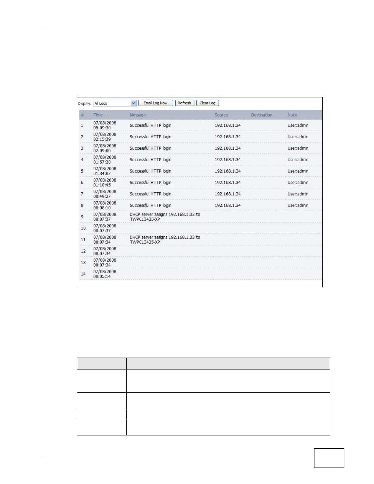
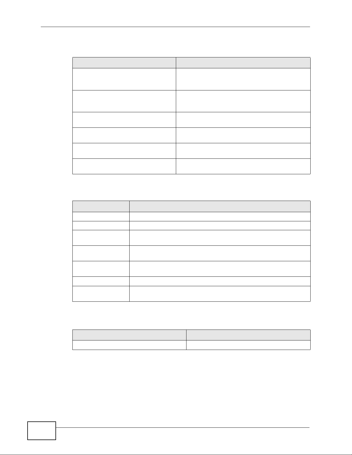
Click TOOLS > Logs > View Log to access this screen. Use this screen to look at
log entries and alerts. Alerts are written in red.
Figure 88 TOOLS > Logs > View Logs
Chapter 18 The Logs Screens
User’s Guide
Click a column header to sort log entries in descending (later-to-earlier) order.
Click again to sort in ascending order. The small triangle next to a column header
indicates how the table is currently sorted (pointing downward is descending;
pointing upward is ascending).
The following table describes the labels in this screen.
Table 77 TOOLS > Logs > View Logs
LABEL DESCRIPTION
Display Select a category whose log entries you want to view. To view all logs,
select All Logs. The list of categories depends on what log categories
are selected in the Log Settings page.
Email Log Now Click this to send the log screen to the e-mail address specified in the
Log Settings page.
Refresh Click to renew the log screen.
Clear Log Click to clear all the log entries, regardless of what is shown on the log
screen.
201
Page 2
Chapter 18 The Logs Screens
Table 77 TOOLS > Logs > View Logs (continued)
LABEL DESCRIPTION
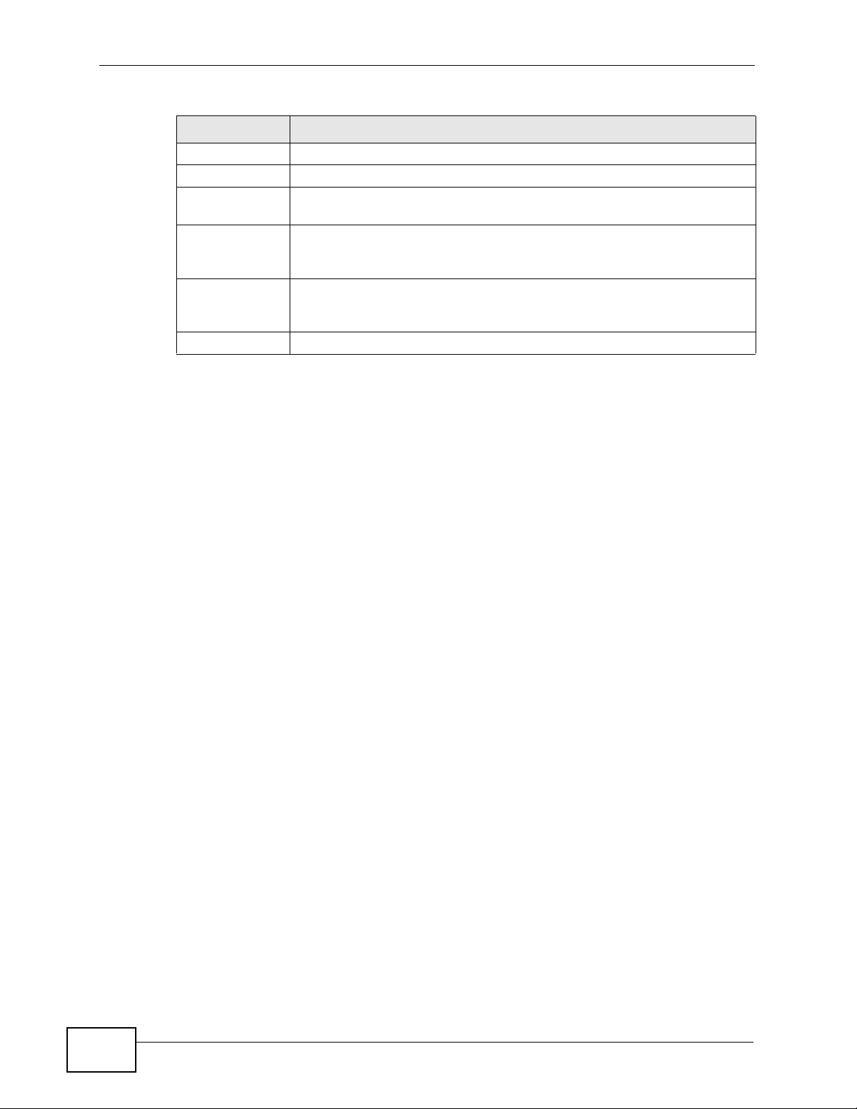
# The number of the item in this list.
Time This field displays the time the log entry was recorded.
Message
Source
Destination This field lists the destination IP address and the port number of the
Note
This field displays the reason for the log entry. See Section 18.4 on
page 205.
This field displays the source IP address and the port number of the
incoming packet. In many cases, some or all of this information may
not be available.
incoming packet. In many cases, some or all of this information may
not be available.
This field displays additional information about the log entry.
202
User’s Guide
Page 3
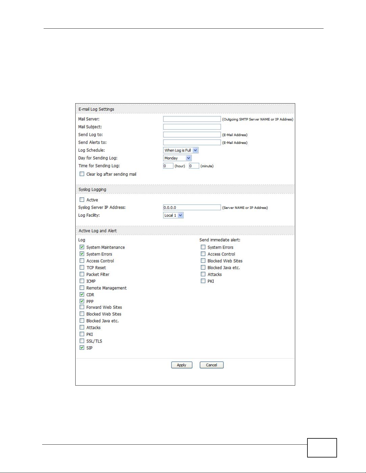
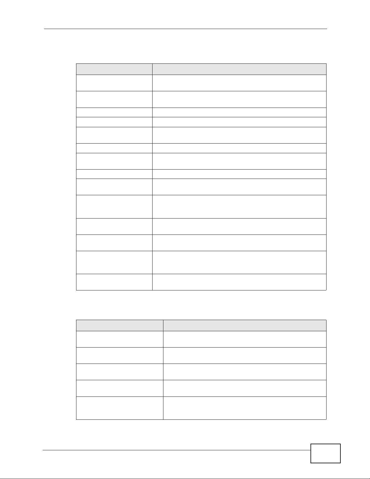
18.3 Log Settings
Click TOOLS > Logs > Log Settings to configure where the WiMAX Modem
sends logs and alerts, the schedule for sending logs, and which logs and alerts are
sent or recorded.
Figure 89 TOOLS > Logs > Log Settings
Chapter 18 The Logs Screens
User’s Guide
203
Page 4

Chapter 18 The Logs Screens
The following table describes the labels in this screen.
Table 78 TOOLS > Logs > Log Settings
LABEL DESCRIPTION
E-mail Log Settings
Mail Server Enter the server name or the IP address of the mail server the WiMAX
Mail Subject Enter the subject line used in e-mail messages the WiMAX Modem
Send Log to Enter the e-mail address to which log entries are sent by e-mail. Leave
Send Alerts to Enter the e-mail address to which alerts are sent by e-mail. Leave this
Log Schedule Select the frequency with which the WiMAX Modem should send log
Day for Sending
Log
Modem should use to e-mail logs and alerts. Leave this field blank if you
do not want to send logs or alerts by e-mail.
sends.
this field blank if you do not want to send logs by e-mail.
field blank if you do not want to send alerts by e-mail.
messages by e-mail.
• Daily
•Weekly
•Hourly
• When Log is Full
•None.
If the Weekly or the Daily option is selected, specify a time of day
when the E-mail should be sent. If the Weekly option is selected, then
also specify which day of the week the E-mail should be sent. If the
When Log is Full option is selected, an alert is sent when the log fills
up. If you select None, no log messages are sent.
This field is only available when you select Weekly in the Log
Schedule field.
Select which day of the week to send the logs.
Time for
Sending Log
Clear log after
sending mail
Syslog Logging
Active Select this to enable syslog logging.
Syslog Server
IP Address
Log Facility Select a location. The log facility allows you to log the messages in
Active Log and Alert
Log
Send
immediate alert
This field is only available when you select Daily or Weekly in the Log
Schedule field.
Enter the time of day in 24-hour format (for example 23:00 equals
11:00 pm) to send the logs.
Select this to clear all logs and alert messages after logs are sent by e-
mail.
Enter the server name or IP address of the syslog server that logs the
selected categories of logs.
different files in the syslog server. See the documentation of your
syslog for more details.
Select the categories of logs that you want to record.
Select the categories of alerts that you want the WiMAX Modem to send
immediately.
204
User’s Guide
Page 5
Table 78 TOOLS > Logs > Log Settings
LABEL DESCRIPTION
Apply Click to save your changes.
Cancel Click to return to the previous screen without saving your changes.
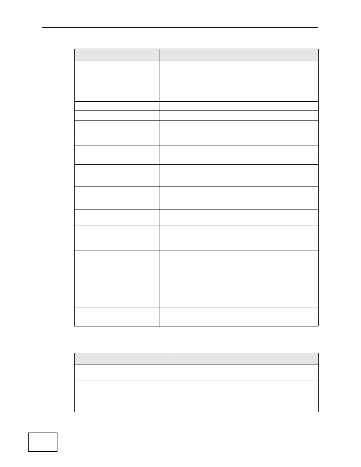
18.4 Log Message Descriptions
The following tables provide descriptions of example log messages.
Table 79 System Error Logs
LOG MESSAGE DESCRIPTION
WAN connection is down. The WAN connection is down. You cannot access the
network through this interface.
%s exceeds the max.
number of session per
host!
This attempt to create a NAT session exceeds the
maximum number of NAT session table entries allowed to
be created per host.
Chapter 18 The Logs Screens
Table 80 System Maintenance Logs
LOG MESSAGE DESCRIPTION
Time calibration is
successful
Time calibration failed The device failed to get information from the time
WAN interface gets IP: %s The WAN interface got a new IP address from the
DHCP client gets %s A DHCP client got a new IP address from the DHCP
DHCP client IP expired A DHCP client's IP address has expired.
DHCP server assigns %s The DHCP server assigned an IP address to a client.
Successful WEB login Someone has logged on to the device's web
WEB login failed Someone has failed to log on to the device's web
TELNET Login Successfully Someone has logged on to the router via telnet.
TELNET Login Fail Someone has failed to log on to the router via telnet.
Successful FTP login Someone has logged on to the device via ftp.
FTP login failed Someone has failed to log on to the device via ftp.
NAT Session Table is Full! The maximum number of NAT session table entries
Time initialized by Daytime
Server
The device has adjusted its time based on information
from the time server.
server.
DHCP or PPPoE server.
server.
configurator interface.
configurator interface.
has been exceeded and the table is full.
The device got the time and date from the Daytime
server.
User’s Guide
205
Page 6

Chapter 18 The Logs Screens
Table 80 System Maintenance Logs (continued)
LOG MESSAGE DESCRIPTION
Time initialized by Time
server
Time initialized by NTP
server
Connect to Daytime server
fail
Connect to Time server fail The device was not able to connect to the Time
Connect to NTP server fail The device was not able to connect to the NTP server.
Too large ICMP packet has
been dropped
Configuration Change: PC =
0x%x, Task ID = 0x%x
Table 81 Access Control Logs
LOG MESSAGE DESCRIPTION
Firewall default policy: [ TCP |
UDP | IGMP | ESP | GRE | OSPF ]
<Packet Direction>
Firewall rule [NOT] match:[ TCP
| UDP | IGMP | ESP | GRE | OSPF
] <Packet Direction>, <rule:%d>
Triangle route packet forwarded:
[ TCP | UDP | IGMP | ESP | GRE |
OSPF ]
Packet without a NAT table entry
blocked: [ TCP | UDP | IGMP |
ESP | GRE | OSPF ]
Router sent blocked web site
message: TCP
Exceed maximum sessions per host
(%d).
Firewall allowed a packet that
matched a NAT session: [ TCP |
UDP ]
The device got the time and date from the time
server.
The device got the time and date from the NTP
server.
The device was not able to connect to the Daytime
server.
server.
The device dropped an ICMP packet that was too
large.
The device is saving configuration changes.
Attempted TCP/UDP/IGMP/ESP/GRE/OSPF access
matched the default policy and was blocked or
forwarded according to the default policy’s
setting.
Attempted TCP/UDP/IGMP/ESP/GRE/OSPF access
matched (or did not match) a configured firewall
rule (denoted by its number) and was blocked or
forwarded according to the rule.
The firewall allowed a triangle route session to
pass through.
The router blocked a packet that didn't have a
corresponding NAT table entry.
The router sent a message to notify a user that
the router blocked access to a web site that the
user requested.
The device blocked a session because the host's
connections exceeded the maximum sessions per
host.
A packet from the WAN (TCP or UDP) matched a
cone NAT session and the device forwarded it to
the LAN.
206
User’s Guide
Page 7

Table 82 TCP Reset Logs
LOG MESSAGE DESCRIPTION
Under SYN flood attack,
sent TCP RST
Exceed TCP MAX
incomplete, sent TCP RST
Peer TCP state out of
order, sent TCP RST
Firewall session time
out, sent TCP RST
The router sent a TCP reset packet when a host was
under a SYN flood attack (the TCP incomplete count is per
destination host.)
The router sent a TCP reset packet when the number of
TCP incomplete connections exceeded the user config ured
threshold. (the TCP incomplete count is per destination
host.)
The router sent a TCP reset packet when a TCP
connection state was out of order.Note: The firewall
refers to RFC793 Figure 6 to check the TCP state.
The router sent a TCP reset packet when a dynamic
firewall session timed out.
The default timeout values are as follows:
ICMP idle timeout: 3 minutes
UDP idle timeout: 3 minutes
Chapter 18 The Logs Screens
TCP connection (three way handshaking) timeout: 270
seconds
TCP FIN-wait timeout: 2 MSL (Maximum Segment
Lifetime set in the TCP header).
TCP idle (established) timeout (s): 150 minutes
TCP reset timeout: 10 seconds
Exceed MAX incomplete,
sent TCP RST
Access block, sent TCP
RST
The router sent a TCP reset packet when the number of
incomplete connections (TCP and UDP) exceeded the
user-configured threshold. (Incomplete count is for all
TCP and UDP connections through the firewall.)Note:
When the number of incomplete connections (TCP + UDP)
> “Maximum Incomplete High” , the router sends TC P RST
packets for TCP connections and destroys TOS (firewall
dynamic sessions) until incomplete connections <
“Maximum Incomplete Low”.
The router sends a TCP RST packet and generates this log
if you turn on the firewall TCP reset mechanism (via CI
command:
sys firewall tcprst).
Table 83 Packet Filter Logs
LOG MESSAGE DESCRIPTION
[ TCP | UDP | ICMP | IGMP |
Generic ] packet filter
matched (set: %d, rule: %d)
Attempted access matched a configured filter rule
(denoted by its set and rule number) and was blocked
or forwarded according to the rule.
User’s Guide
207
Page 8
Chapter 18 The Logs Screens
For type and code details, see Table 90 on page 211.
Table 84 ICMP Logs
LOG MESSAGE DESCRIPTION
Firewall default policy: ICMP
<Packet Direction>, <type:%d>,
<code:%d>
Firewall rule [NOT] match: ICMP
<Packet Direction>, <rule:%d>,
<type:%d>, <code:%d>
Triangle route packet forwarded:
ICMP
Packet without a NAT table entry
blocked: ICMP
Unsupported/out-of-order ICMP:
ICMP
Router reply ICMP packet: ICMP The router sent an ICMP reply packet to the
ICMP access matched the default policy and was
blocked or forwarded according to the user's
setting.
ICMP access matched (or didn’t match) a firewall
rule (denoted by its number) and was blocked or
forwarded according to the rule.
The firewall allowed a triangle route session to
pass through.
The router blocked a packet that didn’t have a
corresponding NAT table entry.
The firewall does not support this kind of ICMP
packets or the ICMP packets are out of order.
sender.
Table 85 PPP Logs
LOG MESSAGE DESCRIPTION
ppp:LCP Starting The PPP connection’s Link Control Protocol stage has started.
ppp:LCP Opening The PPP connection’s Link Control Protocol stage is opening.
ppp:CHAP Opening The PPP connection’s Challenge Handshake Authentication Protocol
stage is opening.
ppp:IPCP
Starting
ppp:IPCP Opening The PPP connection’s Internet Protocol Control Protocol stage is
ppp:LCP Closing The PPP connection’s Link Control Protocol stage is closing.
ppp:IPCP Closing The PPP connection’s Internet Protocol Control Protocol stage is
The PPP connection’s Internet Protocol Control Protocol stage is
starting.
opening.
closing.
Table 86 UPnP Logs
LOG MESSAGE DESCRIPTION
UPnP pass through Firewall UPnP packets can pass through the firewall.
208
User’s Guide
Page 9
Chapter 18 The Logs Screens
Table 87 Content Filtering Logs
LOG MESSAGE DESCRIPTION
%s: Keyword blocking The content of a requested web page matched a user defined
keyword.
%s: Not in trusted web
list
%s: Forbidden Web site The web site is in the forbidden web site list.
%s: Contains ActiveX The web site contains ActiveX.
%s: Contains Java
applet
%s: Contains cookie The web site contains a cookie.
%s: Proxy mode
detected
%s: Trusted Web site The web site is in a trusted domain.
%s When the content filter is not on according to the time
Waiting content
filter server
timeout
DNS resolving
failed
Creating socket
failed
Connecting to
content filter
server fail
License key is
invalid
The web site is not in a trusted domain, and the router blocks
all traffic except trusted domain sites.
The web site contains a Java applet.
The router detected proxy mode in the packet.
schedule:
The external content filtering server did not respond within
the timeout period.
The WiMAX Modem cannot get the IP address of the external
content filtering via DNS query.
The WiMAX Modem cannot issue a query because TCP/UDP
socket creation failed, port:port number.
The connection to the external content filtering server failed.
The external content filtering license key is invalid.
User’s Guide
For type and code details, see Table 90 on page 211.
Table 88 Attack Logs
LOG MESSAGE DESCRIPTION
attack [ TCP | UDP | IGMP
| ESP | GRE | OSPF ]
attack ICMP (type:%d,
code:%d)
land [ TCP | UDP | IGMP |
ESP | GRE | OSPF ]
land ICMP (type:%d,
code:%d)
ip spoofing - WAN [ TCP |
UDP | IGMP | ESP | GRE |
OSPF ]
The firewall detected a TCP/UDP/IGMP/ESP/GRE/OSPF
attack.
The firewall detected an ICMP attack.
The firewall detected a TCP/UDP/IGMP/ESP/GRE/OSPF
land attack.
The firewall detected an ICMP land attack.
The firewall detected an IP spoofing attack on the WAN
port.
209
Page 10
Chapter 18 The Logs Screens
Table 88 Attack Logs (continued)
LOG MESSAGE DESCRIPTION
ip spoofing - WAN ICMP
(type:%d, code:%d)
icmp echo : ICMP
(type:%d, code:%d)
syn flood TCP The firewall detected a TCP syn flood attack.
ports scan TCP The firewall detected a TCP port scan attack.
teardrop TCP The firewall detected a TCP teardrop attack.
teardrop UDP The firewall detected an UDP teardrop attack.
teardrop ICMP (type:%d,
code:%d)
illegal command TCP The firewall detected a TCP illegal command attack.
NetBIOS TCP The firewall detected a TCP NetBIOS attack.
ip spoofing - no routing
entry [ TCP | UDP | IGMP
| ESP | GRE | OSPF ]
ip spoofing - no routing
entry ICMP (type:%d,
code:%d)
vulnerability ICMP
(type:%d, code:%d)
traceroute ICMP (type:%d,
code:%d)
ports scan UDP The firewall detected a UDP port scan attack.
Firewall sent TCP packet
in response to DoS attack
TCP
ICMP Source Quench ICMP The firewall detected an ICMP Source Quench attack.
ICMP Time Exceed ICMP The firewall detected an ICMP Time Exceed attack.
ICMP Destination
Unreachable ICMP
ping of death. ICMP The firewall detected an ICMP ping of death attack.
smurf ICMP The firewall detected an ICMP smurf attack.
The firewall detected an ICMP IP spoofing attack on the
WAN port.
The firewall detected an ICMP echo attack.
The firewall detected an ICMP teardrop attack.
The firewall classified a packet with no source routing
entry as an IP spoofing attack.
The firewall classified an ICMP packet with no source
routing entry as an IP spoofing attack.
The firewall detected an ICMP vulnerability attack.
The firewall detected an ICMP traceroute attack.
The firewall sent TCP packet in response to a DoS attack
The firewall detected an ICMP Destination Unreachable
attack.
210
Table 89 Remote Management Logs
LOG MESSAGE DESCRIPTION
Remote Management: FTP denied Attempted use of FTP service was blocked according
to remote management settings.
Remote Management: TELNET
denied
Remote Management: HTTP or
UPnP denied
Attempted use of TELNET service was blocked
according to remote management settings.
Attempted use of HTTP or UPnP service was block ed
according to remote management settings.
User’s Guide
Page 11

Chapter 18 The Logs Screens
Table 89 Remote Management Logs
LOG MESSAGE DESCRIPTION
Remote Management: WWW denied Attempted use of WWW service was blocked
according to remote management settings.
Remote Management: HTTPS
denied
Remote Management: SSH denied Attempted use of SSH service was blocked
Remote Management: ICMP Ping
response denied
Remote Management: DNS denied Attempted use of DNS service was blocked
Attempted use of HTTPS service was blocked
according to remote management settings.
according to remote management settings.
Attempted use of ICMP service was blocked
according to remote management settings.
according to remote management settings.
Table 90 ICMP Notes
TYPE CODE DESCRIPTION
0 Echo Reply
0 Echo reply message
3 Destination Unreachable
0 Net unreachable
1 Host unreachable
2 Protocol unreachable
3 Port unreachable
4 A packet that needed fragmentation was dropped because it was set
to Don't Fragment (DF)
5 Source route failed
4 Source Quench
0 A gateway may discard internet datagrams if it does not have the
buffer space needed to queue the datagrams for output to the next
network on the route to the destination network.
5 Redirect
0 Redirect datagrams for the Network
1 Redirect datagrams for the Host
2 Redirect datagrams for the Type of Service and Network
3 Redirect datagrams for the Type of Service and Host
8 Echo
0 Echo message
11 Time Exceeded
0 Time to live exceeded in transit
1 Fragment reassembly time exceeded
12 Parameter Problem
0 Pointer indicates the error
13 Timestamp
User’s Guide
211
Page 12
Chapter 18 The Logs Screens
Table 90 ICMP Notes (continued)
TYPE CODE DESCRIPTION
0 Timestamp request message
14 Timestamp Reply
0 Timestamp reply message
15 Information Request
0 Information request message
16 Information Reply
0 Information reply message
Table 91 SIP Logs
LOG MESSAGE DESCRIPTION
SIP Registration Success
by SIP:SIP Phone Number
SIP Registration Fail by
SIP:SIP Phone Number
SIP UnRegistration
Success by SIP:SIP Phone
Number
SIP UnRegistration Fail
by SIP:SIP Phone Number
The listed SIP account was successfully registered with a
SIP register server.
An attempt to register the listed SIP account with a SIP
register server was not successful.
The listed SIP account’s registration was deleted from
the SIP register server.
An attempt to delete the listed SIP account’s registration
from the SIP register server failed.
Table 92 RTP Logs
LOG MESSAGE DESCRIPTION
Error, RTP init fail The initialization of an RTP session failed.
Error, Call fail: RTP
connect fail
Error, RTP connection
cannot close
A VoIP phone call failed because the RTP session could
not be established.
The termination of an RTP session failed.
212
User’s Guide
Page 13
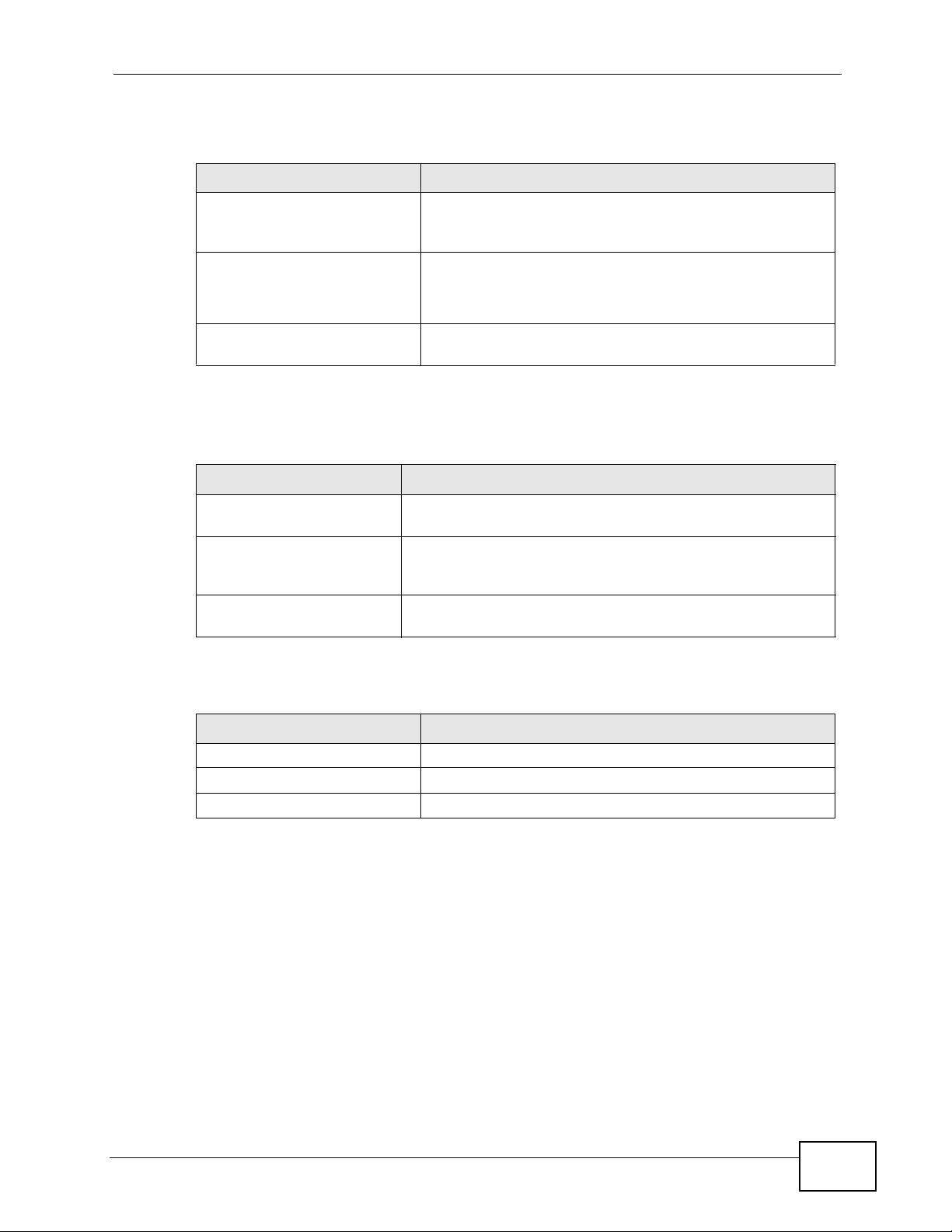
Table 93 FSM Logs: Caller Side
LOG MESSAGE DESCRIPTION
VoIP Call Start Ph[Phone
Port Number] <- Outgoing
Call Number
VoIP Call Established
Ph[Phone Port] ->
Outgoing Call Number
Someone used a phone connected to the listed phone
port to initiate a VoIP call to the listed destination.
Someone used a phone connected to the listed phone
port to make a VoIP call to the listed destination.
Chapter 18 The Logs Screens
VoIP Call End Phone[Phone
Port]
A VoIP phone call made from a phone connected to the
listed phone port has terminated.
Table 94 FSM Logs: Callee Side
LOG MESSAGE DESCRIPTION
VoIP Call Start from
SIP[SIP Port Number]
VoIP Call Established
Ph[Phone Port] <Outgoing Call Number
VoIP Call End
Phone[Phone Port]
A VoIP phone call came to the WiMAX Modem from the
listed SIP number.
A VoIP phone call was set up from the listed SIP number to
the WiMAX Modem.
A VoIP phone call that came into the WiMAX Modem has
terminated.
Table 95 Lifeline Logs
LOG MESSAGE DESCRIPTION
PSTN Call Start A PSTN call has been initiated.
PSTN Call End A PSTN call has terminated.
PSTN Call Established A PSTN call has been set up.
User’s Guide
213
Page 14

Chapter 18 The Logs Screens
214
User’s Guide
Page 15
CHAPTER 19
The Status Screen
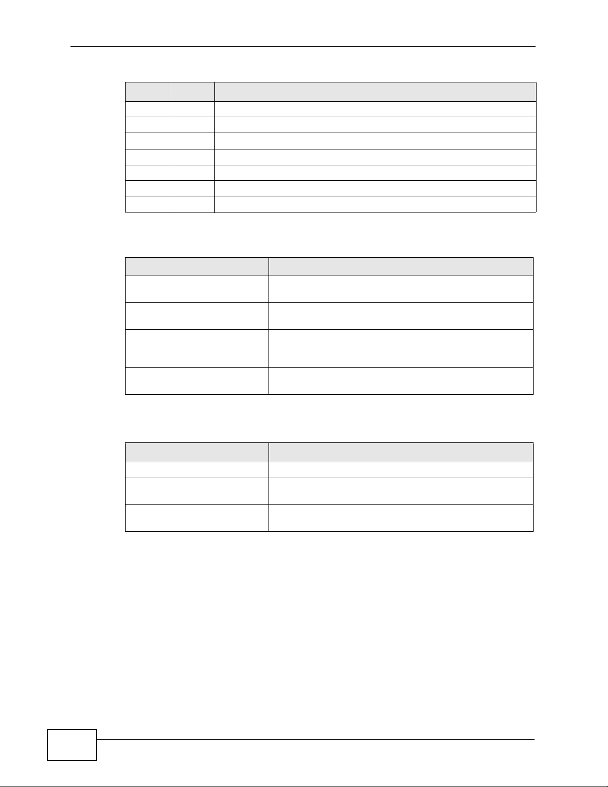
19.1 Overview
Use this screen to view a complete summary of your WiMAX Modem connection
status.
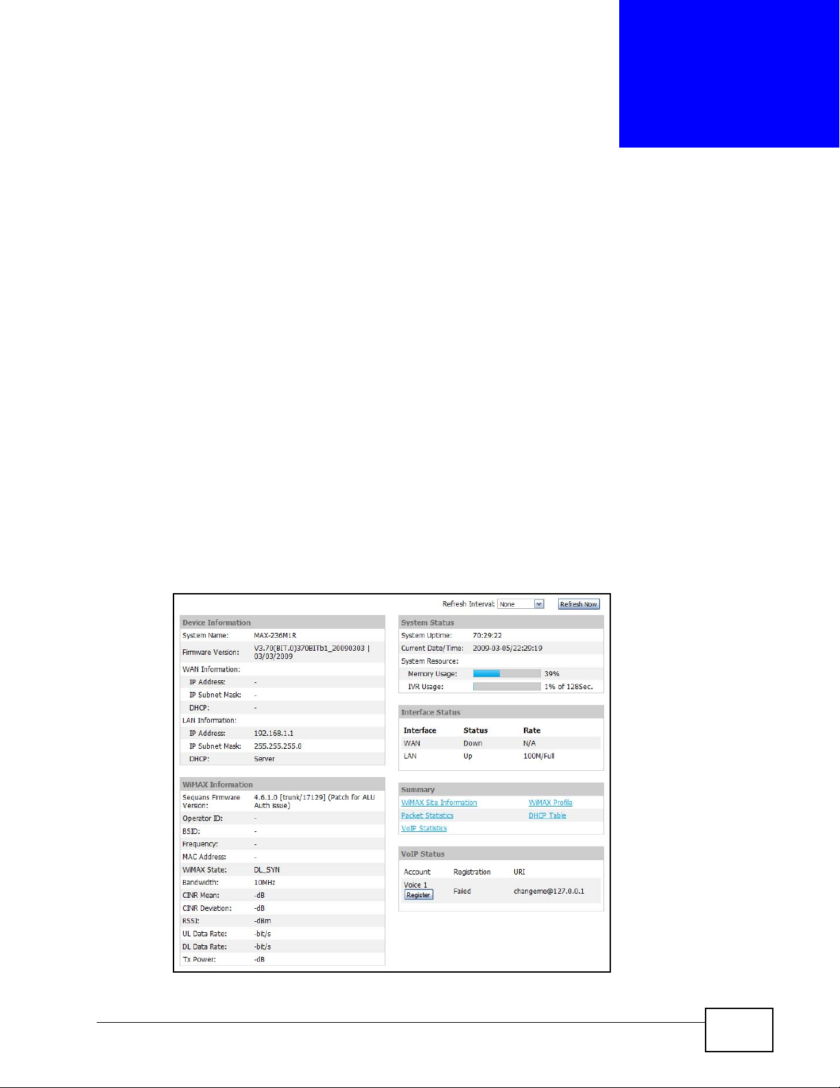
19.2 Status Screen
Click the STATUS icon in the navigation bar to go to this screen, where you can
view the current status of the device, system resources, interfaces (LAN and
WAN), and SIP accounts. You can also register and un-register SIP accounts as
well as view detailed information from DHCP and statistics from WiMAX, VoIP,
bandwidth management, and traffic.
Figure 90 Status
User’s Guide
215
Page 16
Chapter 19 The Status Screen
The following tables describe the labels in this screen.
Table 96 Status
LABEL DESCRIPTION
Refresh Interval Select how often you want the WiMAX Modem to update this screen.
Refresh Now Click this to update this screen immediately.
Device Information
System Name This field displays the WiMAX Modem system name. It is used for
Firmware
Version
WAN Information
IP Address This field displays the current IP address of the WiMAX Modem in the
IP Subnet Mask This field displays the current subnet mask on the WAN.
DHCP This field displays what DHCP services the WiMAX Modem is using in the
identification.
You can change this in the ADVANCED > System Configuration >
General screen’s System Name field.
This field displays the current version of the firmware inside the device.
It also shows the date the firmware version was created.
You can change the firmware version by uploading new firmware in
ADVANCED > System Configuration > Firmware.
WAN.
WAN. Choices are:
Client - The WiMAX Modem is a DHCP client in the WAN. Its IP
address comes from a DHCP server on the WAN.
None - The WiMAX Modem is not using any DHCP services in the
WAN. It has a static IP address.
LAN Information
IP Address This field displays the current IP address of the WiMAX Modem in the
LAN.
IP Subnet Mask This field displays the current subnet mask in the LAN.
DHCP This field displays what DHCP services the WiMAX Modem is providing
to the LAN. Choices are:
Server - The WiMAX Modem is a DHCP server in the LAN. It assigns
IP addresses to other computers in the LAN.
Relay - The WiMAX Modem is routing DHCP requests to one or more
DHCP servers. The DHCP server(s) may be on another network.
None - The WiMAX Modem is not providing any DHCP services to the
LAN.
You can change this in ADVANCED > LAN Configuration > DHCP
Setup.
WiMAX Information
Operator ID Every WiMAX service provider has a unique Operator ID number, which
is broadcast by each base station it owns. You can only connect to the
Internet through base stations belonging to your service provider’s
network.
BSID This field displays the identification number of the wireless base station
to which the WiMAX Modem is connected. Every base station transmits
a unique BSID, which identifies it across the network.
216
User’s Guide
Page 17

Chapter 19 The Status Screen
Table 96 Status (continued)
LABEL DESCRIPTION
Frequency This field displays the radio frequency of the WiMAX Modem’s wireless
connection to a base station.
MAC address This field displays the Media Access Control address of the WiMAX
Modem. Every network device has a unique MAC address which
identifies it across the network.
WiMAX State This field displays the status of the WiMAX Modem’s current connection.
• INIT : the WiMAX Mod e m is starting up .
• DL_SYN: The WiMAX Modem is unable to connect to a base station.
• RANGING: the WiMAX Modem and the base station are transmitting
and receiving information about the distance between them.
Ranging allows the WiMAX Modem to use a lower transmission
power level when communicating with a nearby base station, and a
higher transmission power level when communicating with a distant
base station.
• CAP_NEGO: the WiMAX Modem and the base station are
exchanging information about their capabilities.
• AUTH: the WiMAX Modem and the base station are exchanging
security information.
• REGIST: the WiMAX Modem is registering with a RADIUS server.
• OPERATIONAL: the WiMAX Modem has successfully registered with
the base station. Traffic can now flow between the WiMAX Modem
and the base station.
• IDLE: the WiMAX Modem is in power saving mode, but can connect
when a base station alerts it that there is traffic waiting.
Bandwidth This field shows the size of the bandwidth step the WiMAX Modem uses
to connect to a base station in megahertz (MHz).
CINR mean This field shows the average Carrier to Interference plus Noise Ratio of
the current connection. This value is an indication of over all radio signal
quality. A higher value indicates a higher signal quality, and a lower
value indicates a lower signal quality.
CINR deviation This field shows the amount of change in the CINR level. This value is
an indication of radio signal stability. A lower number indicates a more
stable signal, and a higher number indicates a less stable signal.
RSSI This field shows the Received Signal Strength Indication. This value is a
measurement of overall radio signal strength. A higher RSSI level
indicates a stronger signal, and a lower RSSI level indicates a weaker
signal.
User’s Guide
A strong signal does not necessarily indicate a good signal: a strong
signal may have a low signal-to-noise ratio (SNR).
UL Data Rate This field shows the number of data packets uploaded from the WiMAX
Modem to the base station each second.
DL Data Rate This field shows the number of data packets downloaded to the WiMAX
Modem from the base station each second.
Tx Power This field shows the output transmission (Tx) level of the WiMAX
Modem.
System Status
217
Page 18

Chapter 19 The Status Screen
Table 96 Status (continued)
LABEL DESCRIPTION
System Uptime This field displays how long the WiMAX Modem has been running since
Current Date/
Time
Memory Usage This field displays what percentage of the WiMAX Modem’s memory is
IVR Usage This field displays what percentage of the WiMAX Modem’ s IVR memory
Interface Status
Interface This column displays each interface of the WiMAX Modem.
Status This field indicates whether or not the WiMAX Modem is using the
it last started up. The WiMAX Modem starts up when you plug it in,
when you restart it (ADVANCED > System Configuration >
Restart), or when you reset it.
This field displays the current date and time in the WiMAX Modem. You
can change this in SETUP > Time Setting.
currently used. The higher the memory usage, the more likely the
WiMAX Modem is to slow down. Some memory is required just to start
the WiMAX Modem and to run the web configurator. Y ou can reduce the
memory usage by disabling some services (see CPU Usage); by
reducing the amount of memory allocated to NAT and firewall rules (you
may have to reduce the number of NA T rules or firewall rules to do so);
or by deleting rules in functions such as incoming call policies, speed
dial entries, and static routes.
is currently used. IVR (Interactive Voice Response) refers to the
customizable ring tone and on-hold music you set.
interface.
For the WAN interface, this field displays Up when the WiMAX Modem is
connected to a WiMAX network, and Down when the WiMAX Modem is
not connected to a WiMAX network.
For the LAN interface, this field displays Up when the WiMAX Modem is
using the interface and Down when the WiMAX Modem is not using the
interface.
Rate For the LAN ports this displays the port speed and duplex setting.
For the WAN interface, it displays the downstream and upstream
transmission rate or N/A if the WiMAX Modem is not connected to a
base station.
For the WLAN interface, it displays the transmission rate when WLAN is
enabled or N/A when WLAN is disabled.
Summary
Packet
Statistics
WiMAX Site
Information
DHCP Table Click this link to see details of computers to which the WiMAX Modem
VoIP Statistics Click this link to view statistics about your VoIP usage.
WiMAX Profile Click this link to view details of the current wireless security settings.
VoIP Status
Account This column displays each SIP account in the WiMAX Modem.
Click this link to view port status and packet specific statistics.
Click this link to view details of the radio frequencies used by the
WiMAX Modem to connect to a base station.
has given an IP address.
218
User’s Guide
Page 19
Chapter 19 The Status Screen
Table 96 Status (continued)
LABEL DESCRIPTION
Registration This field displays the current registration status of the SIP account.
You have to register SIP accounts with a SIP server to use VoIP.
If the SIP account is already registered with the SIP server,
Click Unregister to delete the SIP account’s registration in the SIP
server. This does not cancel your SIP account, but it deletes the
mapping between your SIP identity and your IP address or domain
name.
The second field displays Registered.
If the SIP account is not registered with the SIP server,
Click Register to have the WiMAX Modem attempt to register the SIP
account with the SIP server.
The second field displays the reason the account is not registered.
Inactive - The SIP account is not active. You can activate it in VOICE
> SIP > SIP Settings.
Register Fail - The last time the WiMAX Modem tried to register the
SIP account with the SIP server, the attempt failed. The WiMAX Modem
automatically tries to register the SIP account when you turn on the
WiMAX Modem or when you activate it.
URI This field displays the account number and service domain of the SIP
account. You can change these in VOICE > SIP > SIP Settings.
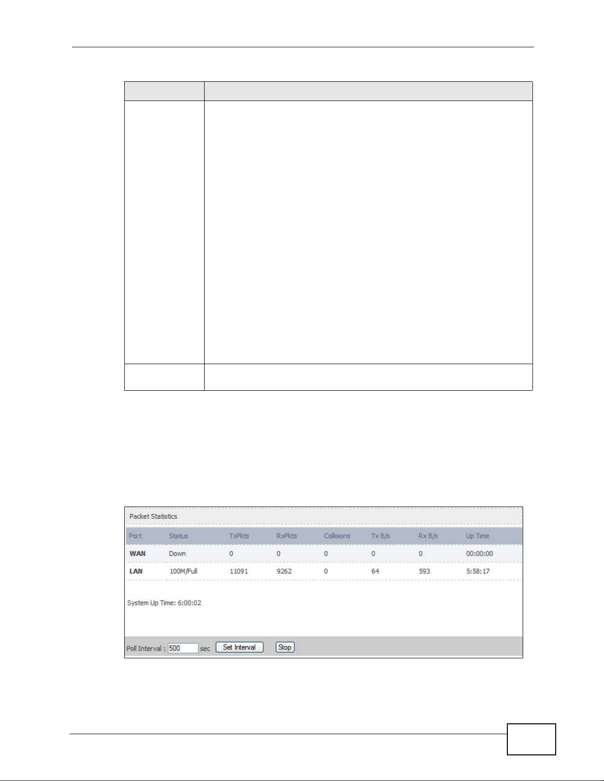
19.2.1 Packet Statistics
Click Status > Packet Statistics to open this screen. This read-only screen
displays information about the data transmission through the WiMAX Modem. To
configure these settings, go to the corresponding area in the Advanced screens.
Figure 91 Packet Statistics
User’s Guide
219
Page 20

Chapter 19 The Status Screen
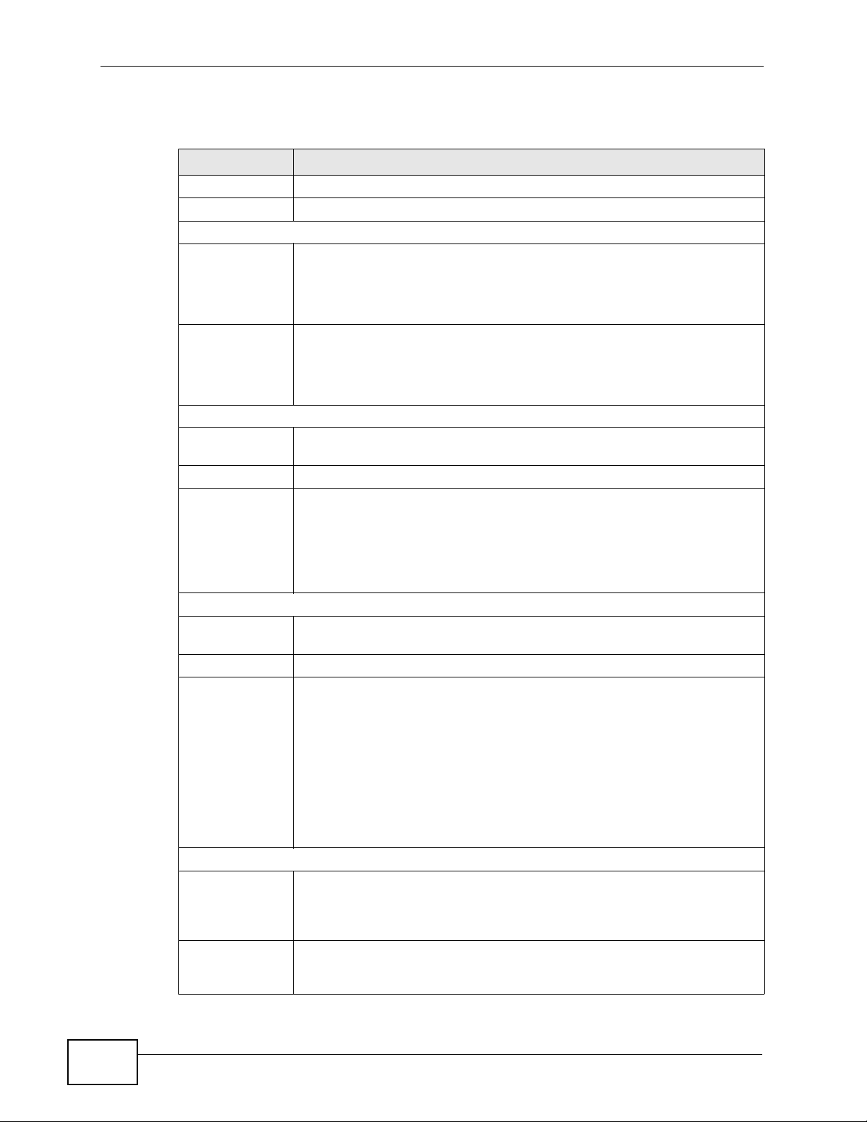
The following table describes the fields in this screen.
Table 97 Packet Statistics
LABEL DESCRIPTION
Port This column displays each interface of the WiMAX Modem.
Status This field indicates whether or not the WiMAX Modem is using the
TxPkts This field displays the number of packets transmitted on this interface.
RxPkts This field displays the number of packets received on this interface.
Collisions This field displays the number of collisions on this port.
Tx B/s This field displays the number of bytes transmitted in the last second.
Rx B/s This field displays the number of bytes received in the last second.
Up Time This field displays the elapsed time this interface has been connected.
System up Time This is the elapsed time the system has been on.
Poll Interval(s) Type the time interval for the browser to refresh system statistics.
Set Interval Click this button to apply the new poll interval you entered in the Poll
Stop Click this button to halt the refreshing of the system statistics.
interface.
For the WAN interface, this field displays the port speed and duplex
setting when the WiMAX Modem is connected to a WiMAX network,
and Down when the WiMAX Modem is not connected to a WiMAX
network.
For the LAN interface, this field displays the port speed and duplex
setting when the WiMAX Modem is using the interface and Down
when the WiMAX Modem is not using the interface.
For the WLAN interface, it displays the transmission rate when WLAN
is enabled or Down when WLAN is disabled.
Interval field above.
220
User’s Guide
Page 21
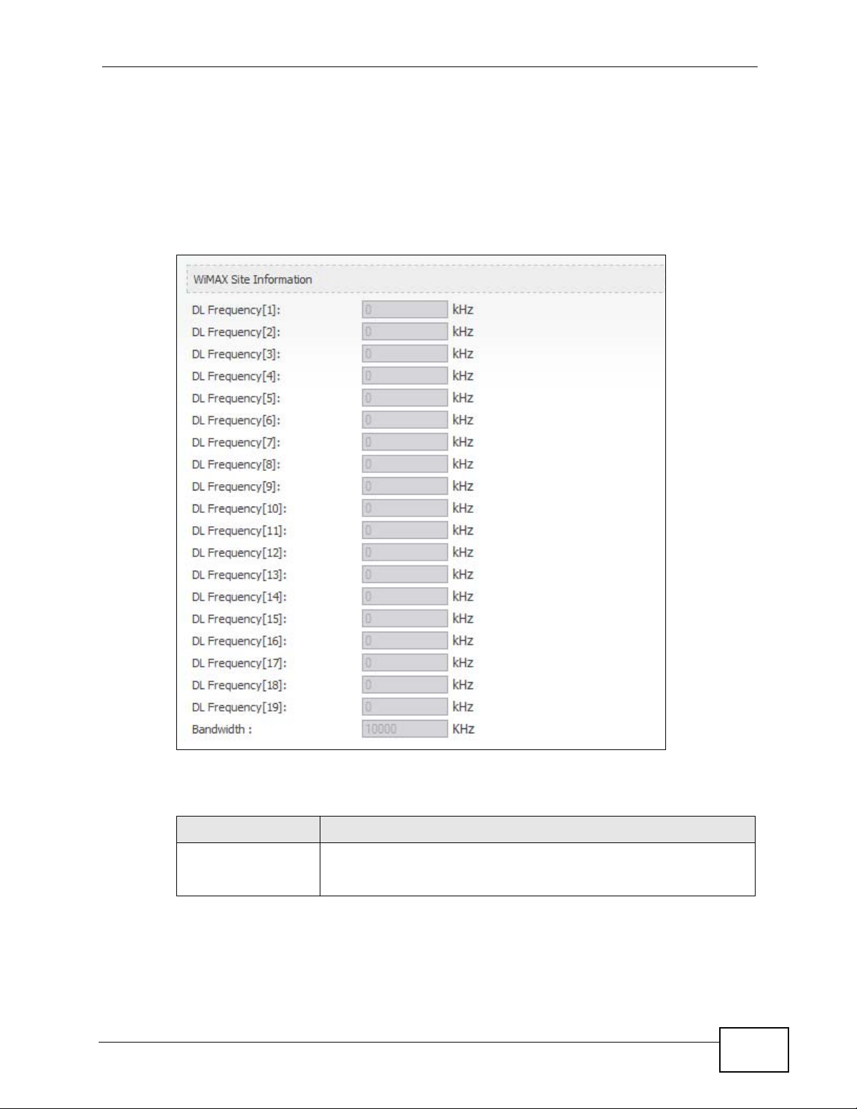
19.2.2 WiMAX Site Information
Click Status > WiMAX Site Information to open this screen. This read-only
screen shows WiMAX frequency information for the WiMAX Modem. These settings
can be configured in the ADVANCED > WAN Configuration > WiMAX
Configuration screen.
Figure 92 WiMAX Site Information
Chapter 19 The Status Screen
User’s Guide
The following table describes the labels in this screen.
Table 98 WiMAX Site Information
LABEL DESCRIPTION
DL Frequency
[1] ~ [19]
These fields show the downlink frequency settings in kilohertz
(kHz). These settings determine how the WiMAX Modem searches
for an available wireless connection.
221
Page 22
Chapter 19 The Status Screen
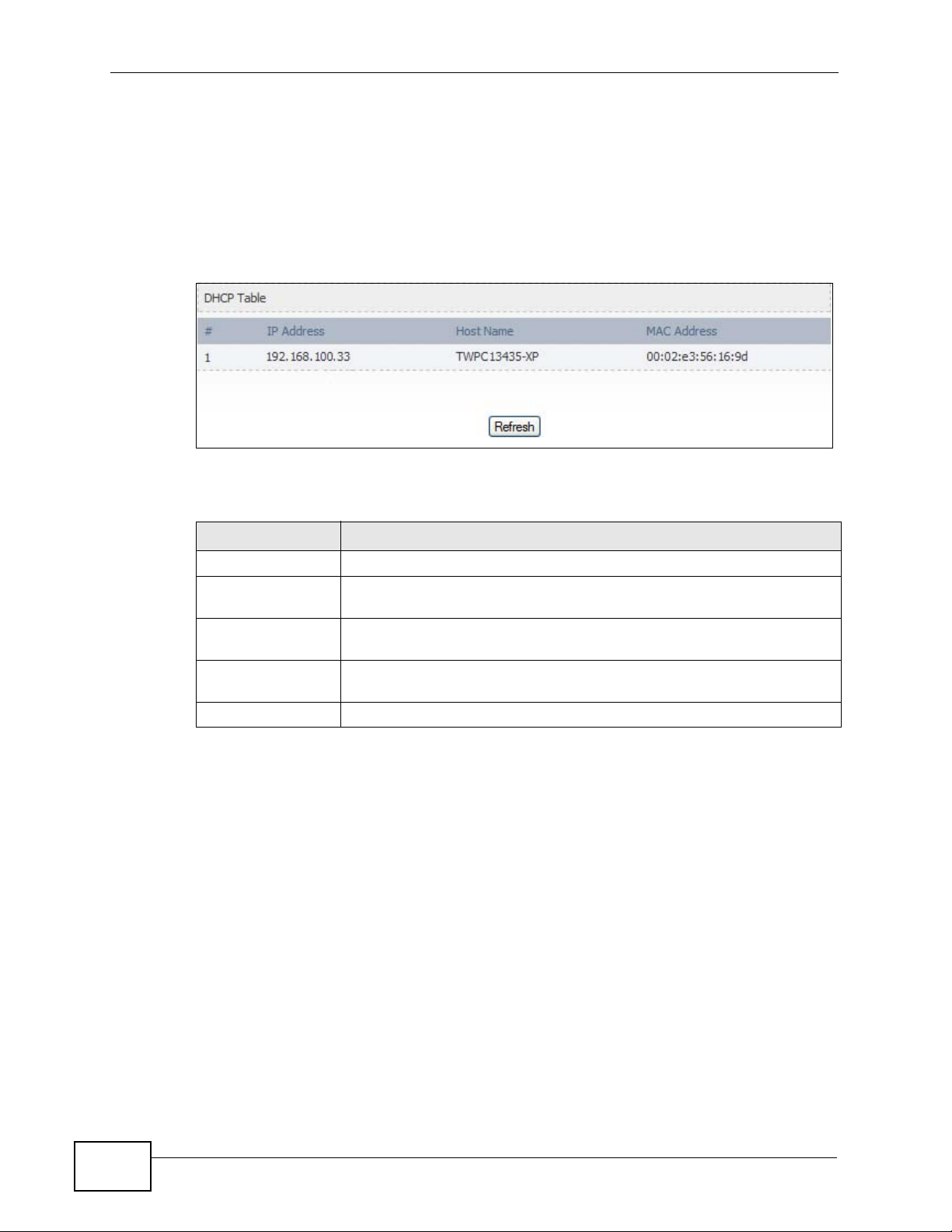
19.2.3 DHCP Table
Click Status > DHCP Table to open this screen. This read-only screen shows the
IP addresses, Host Names and MAC addresses of the devices currently connected
to the WiMAX Modem. These settings can be configured in the ADVANCED > LAN
Configuration > DHCP Setup screen.
Figure 93 DHCP Table
Each field is described in the following table.
Table 99 DHCP Table
LABEL DESCRIPTION
# The number of the item in this list.
IP Address This field displays the IP address the WiMAX Modem assigned to a
Host Name This field displays the system name of the computer to which the
MAC Address This field displays the MAC address of the computer to which the
Refresh Click this button to update the table data.
computer in the network.
WiMAX Modem assigned the IP address.
WiMAX Modem assigned the IP address.
222
User’s Guide
Page 23
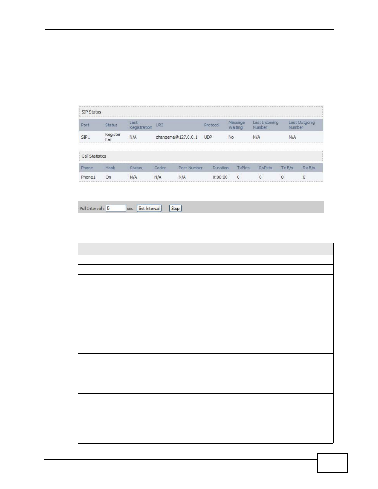
19.2.4 VoIP Statistics
Click Status > DHCP Table to open this screen. This read-only screen shows SIP
registration information, status of calls and VoIP traffic statistics. These settings
can be configured in the VOICE > Service Configuration > SIP Setting screen.
Figure 94 V oIP Statistics
Chapter 19 The Status Screen
Each field is described in the following table.
Table 100 VoIP Statistics
LABEL DESCRIPTION
SIP Status
Port This column displays each SIP account in the WiMAX Modem.
Status This field displays the current registration status of the SIP account.
You can change this in the Status screen.
Registered - The SIP account is registered with a SIP server.
Register Fail - The last time the WiMAX Modem tried to register the
SIP account with the SIP server, the attempt failed. The WiMAX Modem
automatically tries to register the SIP account when you turn on the
WiMAX Modem or when you activate it.
Inactive - The SIP account is not active. You can activate it in VOICE
> SIP > SIP Settings.
Last
Registration
URI This field displays the account number and service domain of the SIP
Protocol This field displays the transport protocol the SIP account uses. SIP
Message
Waiting
Last Incoming
Number
This field displays the last time you successfully registered the SIP
account. It displays N/A if you never successfully registered this
account.
account. You can change these in VOICE > SIP > SIP Settings.
accounts always use UDP.
This field indicates whether or not there are any messages waiting for
the SIP account.
This field displays the last number that called the SIP account. It
displays N/A if no number has ever dialed the SIP account.
User’s Guide
223
Page 24

Chapter 19 The Status Screen
Table 100 VoIP Statistics
LABEL DESCRIPTION
Last Outgoing
Number
Call Statistics
Phone This field displays the WiMAX Modem’s phone port number.
Hook This field indicates whether the phone is on the hook or off the hook.
Status This field displays the current state of the phone call.
Codec This field displays what voice codec is being used for a current VoIP call
Peer Number This field displays the SIP number of the party that is currently engaged
Duration This field displays how long the current call has lasted.
Tx Pkts This field displays the number of packets the WiMAX Modem has
Rx Pkts This field displays the number of packets the WiMAX Modem has
Tx B/s This field displays how quickly the WiMAX Modem has transmitted
Rx B/s This field displays how quickly the WiMAX Modem has received packets
Poll Interval(s) Enter how often you want the WiMAX Modem to update this screen, and
Set Interval Click this to make the WiMAX Modem update the screen based on the
Stop Click this to make the WiMAX Modem stop updating the screen.
This field displays the last number the SIP account called. It displays
N/A if the SIP account has never dialed a number.
On - The phone is hanging up or already hung up.
Off - The phone is dialing, calling, or connected.
N/A - There are no current VoIP calls, incoming calls or outgoing calls
being made.
DIAL - The callee’s phone is ringing.
RING - The phone is ringing for an incoming VoIP call.
Process - There is a VoIP call in progress.
DISC - The callee’s line is busy, the callee hung up or your phone was
left off the hook.
through a phone port.
in a VoIP call through a phone port.
transmitted in the current call.
received in the current call.
packets in the current call. The rate is the average number of bytes
transmitted per second.
in the current call. The rate is the aver age number of bytes tr ansmitted
per second.
click Set Interval.
amount of time you specified in Poll Interval.
224
User’s Guide
Page 25
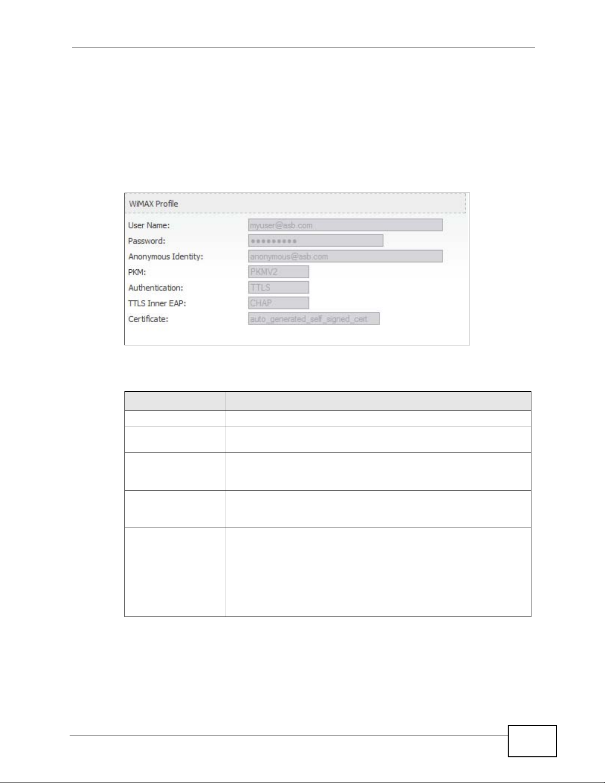
19.2.5 WiMAX Profile
Click Status > WiMAX Profile to open this screen. This read-only screen displays
information about the security settings you are using. To configure these settings,
go to the ADVANCED > WAN Configuration > Internet Connection screen.
Note: Not all WiMAX Modem models have all the fields shown here.
Figure 95 WiMAX Profile
Chapter 19 The Status Screen
The following table describes the labels in this screen.
Table 101 The WiMAX Profile Screen
LABEL DESCRIPTION
User Name This is the username for your Internet access account.
Password This is the password for your Internet access account. The
password displays as a row of asterisks for security purposes.
Anonymous Identity This is the anonymous identity provided by your Internet Service
Provider. Anonymous identity (also known as outer identity) is
used with EAP-TTLS encryption.
PKM This field displays the Privacy Key Management version number.
PKM provides security between the WiMAX Modem and the base
station. See the WiMAX security appendix for more information.
Authentication This field displays the user authentication method. Authentication
is the process of confirming the identity of a user (by means of a
username and password, for example).
EAP-TTLS allows an MS/SS and a base station to establish a
secure link (or ‘tunnel’) with an AAA (Authentication, Authorization
and Accounting) server in order to exchange authentication
information. See the WiMAX security appendix for more details.
User’s Guide
225
Page 26

Chapter 19 The Status Screen
Table 101 The WiMAX Profile Screen (continued)
LABEL DESCRIPTION
TTLS Inner EAP This field displays the type of secondary authentication method.
Certificate This is the security certificate the WiMAX Modem uses to
Once a secure EAP-TTLS connection is established, the inner EAP
is the protocol used to exchange security information between the
mobile station, the base station and the AAA server to
authenticate the mobile station. See the WiMAX security appendix
for more details.
The WiMAX Modem supports the following inner authentication
types:
• CHAP (Challenge Handshake Authentication Protocol)
• MSCHAP (Microsoft CHAP)
• MSCHAPV2 (Microsoft CHAP version 2)
• PAP (Password Authentication Protocol)
authenticate the AAA server, if one is available.
226
User’s Guide
Page 27

PART VI
Troubleshooting
and Specifications
Troubleshooting (229)
Product Specifications (237)
227
Page 28

228
Page 29

CHAPTER 20
Troubleshooting
This chapter offers some suggestions to solve problems you might encounter. The
potential problems are divided into the following categories:
• Power, Hardware Connections, and LEDs
• WiMAX Modem Access and Login
• Internet Access
• Phone Calls and VoIP
• Reset the WiMAX Modem to Its Factory Defaults
20.1 Power, Hardware Connections, and LEDs
The WiMAX Modem does not turn on. None of the LEDs turn on.
1 Make sure you are using the power adapter or cord included with the WiMAX
Modem.
2 Make sure the power adapter or cord is connected to the Wi MA X Mod e m an d
plugged in to an appropriate power source. Make s ure the power source is turned
on.
3 Disconnect and re-connect the power adapter or cord to the WiMAX Modem.
4 If the problem continues, contact the vendor.
One of the LEDs does not behave as expected.
1 Make sure you understand the normal behavior of the LED. See Section 1.2.1 on
User’s Guide
page 34 for more information.
229
Page 30

Chapter 20 Troubleshooting
2 Check the hardware connections. See the Quick Start Guide.
3 Inspect your cables for damage. Contact the vendor to replace any damaged
cables.
4 Disconnect and re-connect the power adapter to the WiMAX Modem.
5 If the problem continues, contact the vendor.
20.2 WiMAX Modem Access and Login
I forgot the IP address for the WiMAX Modem.
1 The default IP address is http://192.168.1.1.
2 If you changed the IP address and have forgotten it, you might get the IP address
of the WiMAX Modem by looking up the IP address of the default gateway for your
computer. To do this in most Windows computers, click Start > Run, enter cmd,
and then enter ipconfig. The IP address of the Default Gateway might be the IP
address of the WiMAX Modem (it depends on the network), so enter this IP
address in your Internet browser.
3 If this does not work, you have to reset the WiMAX Modem to its factory defaults.
See Section 20.1 on page 229.
I forgot the password.
1 The default password is 1234.
2 If this does not work, you have to reset the WiMAX Modem to its factory defaults.
See Section 9.5 on page 106.
I cannot see or access the Login screen in the web configurator.
230
1 Make sure you are using the correct IP address.
• The default IP address is http://192.168.1.1.
User’s Guide
Page 31

Chapter 20 Troubleshooting
• If you changed the IP address (Section 5.2 on page 58), use the new IP
address.
• If you changed the IP address and have forgotten it, see the troubleshooting
suggestions for I forgot the IP address for the WiMAX Modem.
2 Check the hardware connections, and make sure the LEDs are behaving as
expected. See the Quick Start Guide and Section 1.2.1 on page 34.
3 Make sure your Internet browser does not block pop-up windows and has
JavaScript and Java enabled . See Appendix C on page 289.
4 If there is a DHCP server on your network, make sure your computer is using a
dynamic IP address. Your WiMAX Modem is a DHCP server by default.
If there is no DHCP server on your network, make sure your computer’s IP
address is in the same subnet as the WiMAX Modem. See Appendix D on page
299.
5 Reset the WiMAX Modem to its factory defaults, and try to access the WiMAX
Modem with the default IP address. See Section 9.6 on page 107.
6 If the problem continues, contact the network administrator or vendor, or try one
of the advanced suggestions.
Advanced Suggestions
• Try to access the WiMAX Modem using another service, such as Telnet. If you
can access the WiMAX Modem, check the remote management settings and
firewall rules to find out why the WiMAX Modem does not respond to HTTP.
• I f y our comput er is connected wirelessl y, use a computer that is connected to a
LAN/ETHERNET port.
I can see the Login screen, but I cannot log in to the WiMAX Modem.
1 Make sure you have entered the user name and password correctly. The default
user name is admin, and the default password is 1234. These fiel ds are casesensitive, so make sure [Caps Lock] is not on.
2 You cannot log in to the web configurator while someone is using Telnet to access
the WiMAX Modem. Log out of the WiMAX Modem in the other session, or ask the
person who is logged in to log out.
3 Disconnect and re-connect the power adapter or cord to the WiMAX Modem.
4 If this does not work, you have to reset the WiMAX Modem to its factory defaults.
User’s Guide
See Section 9.5 on page 106.
231
Page 32

Chapter 20 Troubleshooting
I cannot Telnet to the WiMAX Modem.
See the troubleshooting suggestions for I cannot see or access the Login screen in
the web configurator. Ignore the suggestions about your browser.
20.3 Internet Access
I cannot access the Internet.
1 Check the hardware connections, and make sure the LEDs are behaving as
expected. See the Quick Start Guide and Section 1.2.1 on page 34.
2 Make sure you entered your ISP acco u nt information co rrectly in the wi z ard.
These fields are case-sensitive, so make sure [Caps Lock] is not on.
3 Check your security settings. In the web configurator, go to the Status screen.
Click the WiMAX Profile link in the Summary box and make sure that you are
using the correct security settings fo r your Internet account.
4 Check your WiMAX settings. The WiMAX Modem may have been set to search the
wrong frequencies for a wireless connection. In the web configurator, go to the
Status screen. Click the WiMAX Site Information link in the Summary box and
ensure that the values are correct. If the values are incorrect, enter the correct
frequency settings in the ADVANCED > WAN Configuration > WiMAX
Configuration screen. If you are unsure of the correct values, contact your
service provider.
5 If you are trying to access the Internet wirelessly, make sure the wireless settings
in the wireless client are the same as the settings in the AP.
6 Disconnect all the cables from your WiMAX Modem, and follow the directions in the
Quick Start Guide again.
7 If the problem continues, contact your ISP.
232
I cannot access the Internet any more. I had access to the Internet (with the
WiMAX Modem), but my Internet connection is not available any more.
User’s Guide
Page 33

Chapter 20 Troubleshooting
1 Check the hardware connections, and make sure the LEDs are behaving as
expected. See the Quick Start Guide and Section 1.2.1 on page 34.
2 Disconnect and re-connect the power adapter to the WiMAX Modem.
3 If the problem continues, contact your ISP.
The Internet connection is slow or intermittent.
1 The quality of the WiMAX Modem’ s wireless connection to the base station may be
poor. Poor signal reception may be improved by moving the WiMAX Modem away
from thick walls and other obstructions, or to a higher floor in your building.
2 There may be radio interference caused by nearby electrical devices such as
microwave ovens and r adi o transmitters. Move the WiMAX Modem away or switch
the other devices off. Weather conditions may also affect signal quality.
3 There might be a lot of traffic on the network. Look at the LEDs, and check Section
1.2.1 on page 34. If the WiMAX Modem is sending or receiving a lot of
information, try closing some programs that use the Internet, especially peer-topeer applications.
4 Disconnect and re-connect the power adapter to the WiMAX Modem.
5 If the problem continues, contact the network administrator or vendor, or try one
of the advanced suggestions.
The Internet connection disconnects.
1 Check your WiMAX link and signal strength using the WiMAX Link and Strength
Indicator LEDs on the device.
2 Contact your ISP if the problem persists.
20.4 Phone Calls and VoIP
The telephone port won’t work or the telephone lacks a dial tone.
User’s Guide
233
Page 34

Chapter 20 Troubleshooting
1 Check the telephone connections and telephone wire.
2 Make sure you have the VOICE > Service Configuration > SIP Settings
screen properly configured (Chapter 10 on page 111).
I can access the Internet, but cannot make VoIP calls.
1 Make sure you have the VOICE > Service Configuration > SIP Settings
screen properly configured (Chapter 10 on page 111).
2 The VoIP LED should come on. Make sure that your telephone is connected to the
VoIP port (see the Quick Start Guide for information on connecting telephone
cables to the these ports).
3 You can also check the VoIP status in the Status screen.
4 If the VoIP settings are correct, use speed dial to make peer-to-peer calls. If you
cannot make a call using speed dial, there may be something wrong with the SIP
server. Contact your VoIP service provider.
Problems With Multiple SIP Accounts
You can set up two SIP accounts on your WiMAX Modem. By default your WiMAX
Modem uses SIP account 1 for outgoing calls, and it uses SIP account s 1 and 2 for
incoming calls. With this setting, you always use SIP account 1 for your outgoing
calls and you cannot distinguish which SIP account the calls are coming in
through. If you want to control the use of different dialing plans for accounting
purposes or other reasons, you need to configure your phone port in order to
control which SIP account you are using when placing or receiving calls.
20.5 Reset the WiMAX Modem to Its Factory
Defaults
If you reset the WiMAX Modem, you lose all of the changes you have made. The
WiMAX Modem re-loads its default settings, and the password resets to 1234. Y ou
have to make all of your changes again.
234
User’s Guide
Page 35

Chapter 20 Troubleshooting
You will lose all of your changes when you push the Reset button.
To reset the WiMAX Modem,
1 Make sure the Power LED is on and not blinking.
2 Press and hold the Reset button for five to ten seconds. Release the Reset button
when the Power LED begins to blink. The default settings have been restored.
If the WiMAX Modem restarts automatically, wait for the WiMAX Modem to finish
restarting, and log in to the web configurator. The password is “1234”.
If the WiMAX Modem does not restart automatically, disconnect and reconnect the
WiMAX Modem’s power. Then, follow the directions above again.
20.5.1 Pop-up Windows, JavaScripts and Java Permissions
Please see Appendix C on page 289.
User’s Guide
235
Page 36

Chapter 20 Troubleshooting
236
User’s Guide
Page 37

CHAPTER 21
Product Specifications
This chapter gives details about your WiMAX Modem’s hardware and firmware
features.
Table 102 Environmental and Hardware Specifications
FEATURE DESCRIPTION
Operating Temperature 0°C to 45°C
Storage Temperature -25°C to 55°C
Operating Humidity 10% ~ 90% (non-condensing)
Storage Humidity 10% to 95% (non-condensing)
Power Supply 12V DC, 2A
Power Consumption 18W
Ethernet Interface One auto-negotiating, auto-MDI/MDI-X NWay 10/100 Mbps
RJ-45 Ethernet port
Telephony Interface One analog ATA interfaces for standard telephones through
RJ-11 FXS (Foreign Exchange Subscriber) analog connector
Antennas Two internal omnidirectional 7dBi WiMAX antenna for MAX-
216M1R.
User’s Guide
Two (optional) SMA external antenna connectors for MAX216M1R plus.
Two internal omnidirectional 6dBi WiMAX antenna for MAX-
206M1R & MAx-236M1R.
Weight 400g
Dimensions 260mm (H) x 165mm (W) x 25mm (D)
Safety Approvals UL 60950-1
CAN/CSA C22.2 No. 60950-1-03
EN 60950-1
IEC 60950-1
EMI Approvals EN 301489-1 v1.6.1
EN 61000-3-2
EN 61000-3-3
237
Page 38

Chapter 21 Product Specifications
Table 102 Environmental and Hardware Specifications (continued)
EMS Approvals EN 301489-4 v1.3.1
RF Approvals EN 302326
Table 103 Radio Specifications
FEATURE DESCRIPTION
Media Access Protocol IEEE 802.16e
WiMAX Bandwidth MAX-216M1R: 5MHz, 7MHz, 10MHz
Data Rate Download:
Modulation QPSK (uplink and downlink)
MAX-206M1R: 5MHz, 10MHz
MAX-236M1R: 5MHz, 8.75MHz, 10MHz
Maximum 15 Mbps
Average 6 Mbps
Upload:
Maximum 5 Mbps
16-QAM (uplink and downlink)
64-QAM (downlink only)
Output Power Typically 27dBm with internal antenna
Duplex mode Time Division Duplex (TDD)
Security PKMv2
EAP
CCMP, 128-bit AES
Table 104 Firmware Specifications
FEATURE DESCRIPTION
Web-based Configuration
and Management Tool
High Speed Wireless
Internet Access
Firewall The WiMAX Modem is a stateful inspection firewall with DoS
Also known as “the web configurator”, this is a firmware-
based management solution for the WiMAX Modem. Y ou must
connect using a compatible web browser in order to use it.
The WiMAX Modem is ideal for high-speed wireless Internet
browsing.
WiMAX (Worldwide Interoperability for Microwave Access) is
a wireless networking standard providing high-bandwidth,
wide-range secured wireless service. The WiMAX Modem is a
WiMAX mobile station (MS) compatible with the IEEE 802.16e
standard.
(Denial of Service) protection. By default, when the firewall is
activated, all incoming traffic from the WAN to the LAN is
blocked unless it is initiated from the LAN. The WiMAX
Modem’s firewall supports TCP/UDP inspection, DoS detection
and prevention, real time alerts, reports and logs.
238
User’s Guide
Page 39

Chapter 21 Product Specifications
Table 104 Firmware Specifications (continued)
FEATURE DESCRIPTION
Content Filtering The WiMAX Modem can block access to web sites containing
specified keywords. You can define time periods and days
during which content filtering is enabled and include or
exclude a range of users on the LAN from content filtering.
Network Address
Translation (NAT)
Universal Plug and Play
(UPnP)
Dynamic DNS Support With Dynamic DNS support, you can have a static hostname
DHCP DHCP (Dynamic Host Configuration Protocol) allows the
IP Alias IP alias allows you to partition a physical network into logical
Multiple SIP Accounts You can configure multiple voice (SIP) accounts.
SIP ALG Your device is a SIP Application Layer Gateway (ALG). It
Dynamic Jitter Buffer The built-in adaptive buffer helps to smooth out the
Voice Activity Detection/
Silence Suppression
Comfort Noise Generation Your device generates background noise to fill moments of
Echo Cancellation You device supports G.168 of at least 24 ms.
Network Address Translation (NAT) allows the translation of
an Internet protocol address used within one ne twork (for
example a private IP address used in a local network) to a
different IP address known within another network (for
example a public IP address used on the Internet).
Your device and other UPnP enabled devices can use the
standard TCP/IP protocol to dynamically join a network,
obtain an IP address and convey their capabilities to each
other.
alias for a dynamic IP address, allowing the host to be more
easily accessible from various locations on the Internet. You
must register for this service with a Dynamic DNS service
provider.
individual clients (computers) to obtain the TCP/IP
configuration at start-up from a centralized DHCP server.
Your device has built-in DHCP server capability enabled by
default. It can assign IP addresses, an IP default gateway
and DNS servers to DHCP clients. Your device can also act as
a surrogate DHCP server (DHCP Relay) where it relays IP
address assignment from the actual real DHCP server to the
clients.
networks over the same Ethernet interface. Your device
supports three logical LAN interfaces via its single physical
Ethernet interface with the your device itself as the gateway
for each LAN network.
allows VoIP calls to pass through NAT for devices behind it
(such as a SIP-based VoIP software application on a
computer).
variations in delay (jitter) for voice traffic (up to 60 ms). This
helps ensure good voice quality for your conversations.
Voice Activity Detection (VAD) reduces the bandwidth that a
call uses by not transmitting when you are not speaking.
silence when the other device in a call stops transmitting
because the other party is not speaking (as total silence
could easily be mistaken for a lost connection).
User’s Guide
This an ITU-T standard for eliminating the echo caused by the
sound of your voice reverberating in the telephone receiver
while you talk.
239
Page 40

Chapter 21 Product Specifications
Table 104 Firmware Specifications (continued)
FEATURE DESCRIPTION
Time and Date Get the current time and date from an external server when
Logging Use the WiMAX Modem’s logging feature to view connection
Codecs Enhanced Variable Rate Codec (EVRC), G.711 (PCM
Fax Support T.38 FAX relay (FAX over UDP).
Ring Tones Supports different distinctive ring tones on each line.
Call Prioritization Prioritize VoIP traffic originating from the RJ-11 ports over
Table 105 Standards Supported
STANDARD DESCRIPTION
RFC 768 User Datagram Protocol
RFC 791 Internet Protocol v4
RFC 792 Internet Control Message Protocol
RFC 792 Transmission Control Protocol
RFC 826 Address Resolution Protocol
RFC 854 Telnet Protocol
RFC 1349 Type of Service Protocol
RFC 1706 DNS NSAP Resource Records
RFC 1889 Real-time Transport Protocol (RTP)
RFC 1890 Real-time Transport Control Protocol (RTCP)
RFC 2030 Simple Network Time Protocol
RFC 2104 HMAC: Keyed-Hashing for Message Authentication
RFC 2131 Dynamic Host Configuration Protocol
RFC 2401 Security Architecture for the Internet Protocol
RFC 2409 Internet Key Exchange
RFC 2475 Architecture for Differentiated Services (Diffserv)
RFC 2617 Hypertext Transfer Protocol (HTTP) Authentication: Basic and
RFC 2782 A DNS RR for specifying the location of services (DNS SRV)
RFC 2833 Real-time Transport Protocol Payload for DTMF Digits,
RFC 2976 The SIP INFO Method
RFC 3261 Session Initiation Protocol (SIP version 2)
RFC 3262 Reliability of Provisional Responses in the Session Initiation
you turn on your WiMAX Modem. You can also set the time
manually.
history, surveillance logs, and error messages.
µ-law
and a-law), G.729a, and G.723.1
G.711 fax relay for fax calls and be able to renegotiate codec
to G.711 if a fax call is detected.
any other traffic.
Digest Access Authentication
Telephony Tones and Telephony Signals
Protocol (SIP).
240
User’s Guide
Page 41

Chapter 21 Product Specifications
Table 105 Standards Supported (continued)
STANDARD DESCRIPTION
RFC 3263 Session Initiation Protocol (SIP): Locating SIP Servers
RFC 3264 An Offer/Answer Model with the Session Description Protocol
(SDP)
RFC 3265 Session Initiation Protocol (SIP)-Specific Event Notification
RFC 3323 A Privacy Mechanism for SIP
RFC 3325 Private Extensions to the Session Initiation Protocol (SIP) for
Asserted Identity within Trusted Networks
RFC 3550 RTP - A Real Time Protocol for Real-Time Applications
RFC 3581 An Extension to the Session Initiation Protocol (SIP) for
Symmetric Response Routing
RFC 3611 RTP Control Protocol Extended Reports (RTCP XR)-XR
RFC 3715 IP Sec/NAT Compatibility
RFC 3842 A Message Summary and Message Waiting Indication Event
Package for the Session Initiation Protocol (SIP)
IEEE 802.3 10BASE5 10 Mbit/s (1.25 MB/s)
IEEE 802.3u 100BASE-TX, 100BASE-T4, 100BASE-FX Fast Ethernet at 100
Mbit/s (12.5 MB/s) with auto-negotiation
Table 106 Voice Features
Call Park and
Pickup
Call Return With call return, you can place a call to the last number that called
Country Code Phone standards and settings differ from one country to another, so
Do not Disturb
(DnD)
Auto Dial You can set the WiMAX Modem to automatically dial a specified
Call park and pickup lets you put a call on hold (park) and then
continue the call (pickup). The caller must still pay while the call is
parked.
When you park the call, you enter a number of your choice (up to
eight digits), which you must enter again when you pick up the call. If
you do not enter the correct number, you cannot pickup the call. This
means that only someone who knows the number you have chosen
can pick up the call.
You can have more than one call on hold at the same time, but you
must give each call a different number.
you (either answered or missed). The last incoming call can be
through either SIP or PSTN.
the settings on your WiMAX Modem must be configured to match
those of the country you are in. The country code feature allows you
to do this by selecting the country from a list rather than changing
each setting manually. Configure the country code feature when you
move the WiMAX Modem from one country to another.
This feature allows you to set your phone not to ring when someone
calls you. You can set each phone independently using its keypad, or
configure global settings for all phones using the command line
interpreter.
number immediately whenever you lift a phone off the hook. Use the
Web Configurator to set the specified number. Use the command line
interpreter to have the WiMAX Modem wait a specified length of time
before dialing the number.
User’s Guide
241
Page 42

Chapter 21 Product Specifications
Table 106 Voice Features
Phone config The phone configuration table allows you to customize the phone
Firmware update
enable / disable
Call waiting This feature allows you to hear an alert when you are already using
Call forwarding With this feature, you can set the WiMAX Modem to forward calls to a
Caller ID The WiMAX Modem supports caller ID, which allows you to see the
REN A Ringer Equivalence Number (REN) is used to determine the number
QoS (Quality of
Service)
keypad combinations you use to access certain features on the
WiMAX Modem, such as call waiting, call return, call forward, etc. The
phone configuration table is configurable in command interpreter
mode.
If your service provider uses this feature, you hear a recorded
message when you pick up the phone when new firmware is available
for your W iMAX Mode m. Enter * 99# in your phone’s keypad to have
the WiMAX Modem upgrade the firmware, or enter #99# to not
upgrade. If your service provider gave you different numbers to use,
enter them instead. If you enter the code to not upgrade, you can
make a call as normal. You will hear the recording again each time
you pick up the phone, until you upgrade.
the phone and another person calls you. You can then either reject
the new incoming call, put your current call on hold and receive the
new incoming call, or end the current call and receive the new
incoming call.
specified number, either unconditionally (always), when your number
is busy, or when you do not answer. You can also forward incoming
calls from one specified number to another.
originating number of an incoming call (on a phone with a suitable
display).
of devices (like telephones or fax machines) that may be connected
to the telephone line. Your device has a REN of three, so it can
support three devices per telephone port.
Quality of Service (QoS) mechanisms help to provide better service
on a per-flow basis. Your device supports Type of Service (ToS)
tagging and Differentiated Services (DiffServ) tagging. This allows
the device to tag voice frames so they can be prioritized over the
network.
242
User’s Guide
Page 43

Chapter 21 Product Specifications
Table 106 Voice Features
SIP ALG Your device is a SIP Application Layer Gateway (ALG). It allows VoIP
calls to pass through NAT for devices behind it (such as a SIP-based
VoIP software application on a computer).
Other Voice
Features
SIP version 2 (Session Initiating Protocol RFC 3261)
SDP (Session Description Protocol RFC 2327)
RTP (RFC 1889)
RTCP (RFC 1890)
Voice codecs (coder/decoders) G.711, G.726, G.729
Fax and data modem discrimination
DTMF Detection and Generation
DTMF: In-band and Out-band traffic (RFC 2833),(PCM), (SIP INFO)
Point-to-point call establishment between two IADs
Quick dialing through predefined phone book, which maps the phone
dialing number and destination URL.
Flexible Dial Plan (RFC3525 section 7.1.14)
Table 107 Star (*) and Pound (#) Code Support
*0 Wireless Operator Services
*2 Customer Care Access
*66 Repeat Dialing
*67 Plus the 10 digit phone number to block Caller ID on a single call
basis
*69 Return last call received
*70 Followed by the 10 digit phone number to cancel Call Wa iting on a
single call basis
*72 Activate Call Forwarding (*72 followed by the 10 digit phone number
that is requesting call forwarding service)
*720 Activate Call Forwarding (*720 followed by the 10 digit phone
number that is requesting deactivation of call forwarding service)
*73 Plus the forward to phone number to activate Call Forwarding No
Answer (no VM service plan)
*730 Deactivate Call Forwarding No Answer
*740 Plus the forward to phone number to activate Call Forwarding Busy
(no VM service plan)
*911/911 Emergency phone number (same as dialing 911)
*411/411 Wireless Information Services
User’s Guide
Table 108 Environmental and Hardware Specifications
FEATURE DESCRIPTION
Operating Temperature 0°C to 45°C
Storage Temperature -25°C to 55°C
243
Page 44

Chapter 21 Product Specifications
Table 108 Environmental and Hardware Specifications (continued)
Operating Humidity 20% ~ 90% (non-condensing)
Storage Humidity 10% to 95% (non-condensing)
Power Supply 12V DC, 2 A
Power consumption 18W
Ethernet Interface Two auto-negotiating, auto-MDI/MDI-X NWay 10/100 Mbps
Telephony Interface Two analog ATA interfaces for standard telephones through
Antennas Two internal 5dBi WiMAX antennas
Weight 480g
Dimensions 160mm (W) x 118mm (D) x 167mm (H)
Safety Approvals UL 60950-1
EMI Approvals EN 301489-1 v1.6.1
RJ-45 Ethernet ports
RJ-11 FXS (Foreign Exchange Subscriber) analog connector
CAN/CSA C22.2 No. 60950-1-03
EN 60950-1
IEC 60950-1
EN 61000-3-2
EN 61000-3-3
EMS Approvals EN 301489-4 v1.3.1
RF Approvals EN 302326
Table 109 Radio Specifications
FEATURE DESCRIPTION
Media Access Protocol IEEE 802.16e
WiMAX Bandwidth 2.5 GHz
Data Rate Download:
Maximum 20 Mbps
Average 6 Mbps
Upload:
Maximum 4 Mbps
Average 3 Mbps
Modulation QPSK (uplink and downlink)
16-QAM (uplink and downlink)
64-QAM (downlink only)
Output Power 27dBm with external antennas attached
Duplex mode Time Division Duplex (TDD)
Security PKMv2
244
EAP
CCMP, 128-bit AES
User’s Guide
Page 45

Chapter 21 Product Specifications
Table 110 Firmware Specifications
FEATURE DESCRIPTION
Web-based Configuration
and Management Tool
High Speed Wireless
Internet Access
Firewall The WiMAX Modem is a stateful inspection firewall with DoS
Content Filtering The WiMAX Modem can block access to web sites containing
Network Address
Translation (NAT)
Universal Plug and Play
(UPnP)
Dynamic DNS Support With Dynamic DNS support, you can have a static hostname
DHCP DHCP (Dynamic Host Configuration Protocol) allows the
IP Alias IP alias allows you to partition a physical network into logical
Multiple SIP Accounts You can configure multiple voice (SIP) accounts.
Also known as “the web configurator”, this is a firmware-
based management solution for the WiMAX Modem. Y ou must
connect using a compatible web browser in order to use it.
The WiMAX Modem is ideal for high-speed wireless Internet
browsing.
WiMAX (Worldwide Interoperability for Microwave Access) is
a wireless networking standard providing high-bandwidth,
wide-range secured wireless service. The WiMAX Modem is a
WiMAX mobile station (MS) compatible with the IEEE 802.16e
standard.
(Denial of Service) protection. By default, when the firewall is
activated, all incoming traffic from the WAN to the LAN is
blocked unless it is initiated from the LAN. The WiMAX
Modem’s firewall supports TCP/UDP inspection, DoS detection
and prevention, real time alerts, reports and logs.
specified keywords. You can define time periods and days
during which content filtering is enabled and include or
exclude a range of users on the LAN from content filtering.
Network Address Translation (NAT) allows the translation of
an Internet protocol address used within one ne twork (for
example a private IP address used in a local network) to a
different IP address known within another network (for
example a public IP address used on the Internet).
Your device and other UPnP enabled devices can use the
standard TCP/IP protocol to dynamically join a network,
obtain an IP address and convey their capabilities to each
other.
alias for a dynamic IP address, allowing the host to be more
easily accessible from various locations on the Internet. You
must register for this service with a Dynamic DNS service
provider.
individual clients (computers) to obtain the TCP/IP
configuration at start-up from a centralized DHCP server.
Your device has built-in DHCP server capability enabled by
default. It can assign IP addresses, an IP default gateway
and DNS servers to DHCP clients. Your device can also act as
a surrogate DHCP server (DHCP Relay) where it relays IP
address assignment from the actual real DHCP server to the
clients.
networks over the same Ethernet interface. Your device
supports three logical LAN interfaces via its single physical
Ethernet interface with the your device itself as the gateway
for each LAN network.
User’s Guide
245
Page 46

Chapter 21 Product Specifications
Table 110 Firmware Specifications (continued)
FEATURE DESCRIPTION
SIP ALG Your device is a SIP Application Layer Gateway (ALG). It
Dynamic Jitter Buffer The built-in adaptive buffer helps to smooth out the
Voice Activity Detection/
Silence Suppression
Comfort Noise Generation Your device generates background noise to fill moments of
Echo Cancellation You device supports G.168 of at least 24 ms.
Time and Date Get the current time and date from an external server when
Logging Use the WiMAX Modem’s logging feature to view connection
Codecs Enhanced Variable Rate Codec (EVRC), G.711 (PCM
Fax Support T.38 FAX relay (FAX over UDP).
allows VoIP calls to pass through NAT for devices behind it
(such as a SIP-based VoIP software application on a
computer).
variations in delay (jitter) for voice traffic (up to 60 ms). This
helps ensure good voice quality for your conversations.
Voice Activity Detection (VAD) reduces the bandwidth that a
call uses by not transmitting when you are not speaking.
silence when the other device in a call stops transmitting
because the other party is not speaking (as total silence
could easily be mistaken for a lost connection).
This an ITU-T standard for eliminating the echo caused by the
sound of your voice reverberating in the telephone receiver
while you talk.
you turn on your WiMAX Modem. You can also set the time
manually.
history, surveillance logs, and error messages.
µ-law
and a-law), G.729a, and G.723.1
G.711 fax relay for fax calls and be able to renegotiate codec
to G.711 if a fax call is detected.
Ring Tones Supports different distinctive ring tones on each line.
Call Prioritization Prioritize VoIP traffic originating from the RJ-11 ports over
any other traffic.
Table 111 Standards Supported
STANDARD DESCRIPTION
RFC 768 User Datagram Protocol
RFC 791 Internet Protocol v4
RFC 792 Internet Control Message Protocol
RFC 792 Transmission Control Protocol
RFC 826 Address Resolution Protocol
RFC 854 Telnet Protocol
RFC 1349 Type of Service Protocol
RFC 1706 DNS NSAP Resource Records
RFC 1889 Real-time Transport Protocol (RTP)
RFC 1890 Real-time Transport Control Protocol (RTCP)
RFC 2030 Simple Network Time Protocol
246
User’s Guide
Page 47

Chapter 21 Product Specifications
Table 111 Standards Supported (continued)
STANDARD DESCRIPTION
RFC 2104 HMAC: Keyed-Hashing for Message Authentication
RFC 2131 Dynamic Host Configuration Protocol
RFC 2401 Security Architecture for the Internet Protocol
RFC 2409 Internet Key Exchange
RFC 2475 Architecture for Differentiated Services (Diffserv)
RFC 2617 Hypertext Transfer Protocol (HTTP) Authentication: Basic and
Digest Access Authentication
RFC 2782 A DNS RR for specifying the location of services (DNS SRV)
RFC 2833 Real-time Transport Protocol Payload for DTMF Digits,
Telephony Tones and Telephony Signals
RFC 2976 The SIP INFO Method
RFC 3261 Session Initiation Protocol (SIP version 2)
RFC 3262 Reliability of Provisional Responses in the Session Initiation
Protocol (SIP).
RFC 3263 Session Initiation Protocol (SIP): Locating SIP Servers
RFC 3264 An Offer/Answer Model with the Session Description Protocol
(SDP)
RFC 3265 Session Initiation Protocol (SIP)-Specific Event Notification
RFC 3323 A Privacy Mechanism for SIP
RFC 3325 Private Extensions to the Session Initiation Protocol (SIP) for
Asserted Identity within Trusted Networks
RFC 3550 RTP - A Real Time Protocol for Real-Time Applications
RFC 3581 An Extension to the Session Initiation Protocol (SIP) for
Symmetric Response Routing
RFC 3611 RTP Control Protocol Extended Reports (RTCP XR)-XR
RFC 3715 IP Sec/NAT Compatibility
RFC 3842 A Message Summary and Message Waiting Indication Event
Package for the Session Initiation Protocol (SIP)
IEEE 802.3 10BASE5 10 Mbit/s (1.25 MB/s)
IEEE 802.3u 100BASE-TX, 100BASE-T4, 100BASE-FX Fast Ethernet at 100
Mbit/s (12.5 MB/s) with auto-negotiation
User’s Guide
247
Page 48

Chapter 21 Product Specifications
Table 112 Voice Features
Call Park and
Pickup
Call Return With call return, you can place a call to the last number that called
Country Code Phone standards and settings differ from one country to another, so
Do not Disturb
(DnD)
Auto Dial You can set the WiMAX Modem to automatically dial a specified
Phone config The phone config table allows you to customize the phone keypad
Firmware update
enable / disable
Call waiting This feature allows you to hear an alert when you are already using
Call forwarding With this feature, you can set the WiMAX Modem to forward calls to a
Call park and pickup lets you put a call on hold (park) and then
continue the call (pickup). The caller must still pay while the call is
parked.
When you park the call, you enter a number of your choice (up to
eight digits), which you must enter again when you pick up the call. If
you do not enter the correct number, you cannot pickup the call. This
means that only someone who knows the number you have chosen
can pick up the call.
You can have more than one call on hold at the same time, but you
must give each call a different number.
you (either answered or missed). The last incoming call can be
through either SIP or PSTN.
the settings on your WiMAX Modem must be configured to match
those of the country you are in. The country code feature allows you
to do this by selecting the country from a list rather than changing
each setting manually. Configure the country code feature when you
move the WiMAX Modem from one country to another.
This feature allows you to set your phone not to ring when someone
calls you. You can set each phone independently using its keypad, or
configure global settings for all phones using the command line
interpreter.
number immediately whenever you lift a phone off the hook. Use the
Web Configurator to set the specified number. Use the command line
interpreter to have the WiMAX Modem wait a specified length of time
before dialing the number.
combinations you use to access certain features on the WiMAX
Modem, such as call waiting, call return, call forward, etc. The phone
config table is configurable in command interpreter mode.
If your service provider uses this feature, you hear a recorded
message when you pick up the phone when new firmware is available
for your W iMAX Mode m. Enter * 99# in your phone’s keypad to have
the WiMAX Modem upgrade the firmware, or enter #99# to not
upgrade. If your service provider gave you different numbers to use,
enter them instead. If you enter the code to not upgrade, you can
make a call as normal. You will hear the recording again each time
you pick up the phone, until you upgrade.
the phone and another person calls you. You can then either reject
the new incoming call, put your current call on hold and receive the
new incoming call, or end the current call and receive the new
incoming call.
specified number, either unconditionally (always), when your number
is busy, or when you do not answer. You can also forward incoming
calls from one specified number to another.
248
User’s Guide
Page 49

Chapter 21 Product Specifications
Table 112 Voice Features
Caller ID The WiMAX Modem supports caller ID, which allows you to see the
originating number of an incoming call (on a phone with a suitable
display).
REN A Ringer Equivalence Number (REN) is used to determine the number
of devices (like telephones or fax machines) that may be connected
to the telephone line. Your device has a REN of three, so it can
support three devices per telephone port.
QoS (Quality of
Service)
SIP ALG Your device is a SIP Application Layer Gateway (ALG). It allows VoIP
Other Voice
Features
Quality of Service (QoS) mechanisms help to provide better service
on a per-flow basis. Your device supports Type of Service (ToS)
tagging and Differentiated Services (DiffServ) tagging. This allows
the device to tag voice frames so they can be prioritized over the
network.
calls to pass through NAT for devices behind it (such as a SIP-based
VoIP software application on a computer).
SIP version 2 (Session Initiating Protocol RFC 3261)
SDP (Session Description Protocol RFC 2327)
RTP (RFC 1889)
RTCP (RFC 1890)
Voice codecs (coder/decoders) G.711, G.726, G.729
Fax and data modem discrimination
DTMF Detection and Generation
DTMF: In-band and Out-band traffic (RFC 2833),(PCM), (SIP INFO)
Point-to-point call establishment between two IADs
Quick dialing through predefined phone book, which maps the phone
dialing number and destination URL.
Flexible Dial Plan (RFC3525 section 7.1.14)
Table 113 Star (*) and Pound (#) Code Support
*0 Wireless Operator Services
*2 Customer Care Access
*66 Repeat Dialing
*67 Plus the 10 digit phone number to block Caller ID on a single call
basis
*69 Return last call received
*70 Followed by the 10 digit phone number to cancel Call Wa iting on a
single call basis
*72 Activate Call Forwarding (*72 followed by the 10 digit phone number
that is requesting call forwarding service)
*720 Activate Call Forwarding (*720 followed by the 10 digit phone
number that is requesting deactivation of call forwarding service)
*73 Plus the forward to phone number to activate Call Forwarding No
Answer (no VM service plan)
User’s Guide
249
Page 50

Chapter 21 Product Specifications
Table 113 Star (*) and Pound (#) Code Support
*730 Deactivate Call Forwarding No Answer
*740 Plus the forward to phone number to activate Call Forwarding Busy
*911/911 Emergency phone number (same as dialing 911)
*411/411 Wireless Information Services
Note: To take full advantage of the supplementary phone services available through
the WiMAX Modem's phone port, you may need to subscribe to the services
from your voice account service provider.
Not all features are supported by all service providers. Consult your service
provider for more information.
(no VM service plan)
250
User’s Guide
Page 51

21.1 Wall-Mounting
This section shows you how to mount your WiMAX Modem on a wall using the
ZyXEL Wall-Mounting kit (not included).
21.1.1 The Wall-Mounting Kit
The wall-mounting kit contains the following parts:
12 3
Chapter 21 Product Specifications
1 Two Mortar Plugs (M4*L30 mm)
2 Two Screws (M4*L30 mm)
3 Wall-Mounting Chassis
If any parts are missing, contact your vendor.
21.1.2 Instructions
To mount the WiMAX Modem on a wall:
1 Select a position free of obstructions on a sturdy wall.
2 Drill two holes in the wall exactly 70 mm apart. The holes should be 6 mm wide
and at least 30 mm deep.
Be careful to avoid damaging pipes or cables located inside the
wall when drilling holes for the screws.
User’s Guide
251
Page 52

Chapter 21 Product Specifications
3 Attach the wall mounting chassis with the plugs and screws as shown below:
4 Connect the MAX-216M1 to the wall mounting chassis by snapping the chassis’
two upper chassis hooks into the matching holes on the WiMAX Modem:
252
Do not pinch or server the cable connections between the wallmounting chassis the WiMAX Modem.
User’s Guide
Page 53

Chapter 21 Product Specifications
5 Snap the lower chassis hooks into the matching holes on the WiMAX Modem. The
cable connections should come out either the left or right gaps between the wallmounting chassis and the WiMAX Modem
6 Once you have snapped the wall-mounting chassis in place, the WiMAX Modem is
securely fastened to the wall.
User’s Guide
253
Page 54

Chapter 21 Product Specifications
254
User’s Guide
Page 55

PART VII
Appendices and
Index
WiMAX Security (257)
Setting Up Your Computer’s IP Address
(261)
Pop-up Windows, JavaScripts and Java
Permissions (289)
IP Addresses and Subnetting (299)
Importing Certificates (311)
SIP Passthrough (343)
Common Services (345)
Legal Information (349)
Customer Support (353)
255
Page 56

256
Page 57

APPENDIX A
WiMAX Security
Wireless security is vital to protect your wireless com mun ications. Without it,
information transmitted over the wireless network would be accessible to any
networking device within range.
User Authentication and Data Encryption
The WiMAX (IEEE 802.16) standard employs user authentication and encryption to
ensure secured communication at all times.
User authentication is the process of confirming a user’s identity and level of
authorization. Data encryption is the process of encoding information so that it
cannot be read by anyone who does not know the code.
PKMv2
WiMAX uses PKMv2 (Privacy Key Management version 2) for authentication, and
CCMP (Counter Mode with Cipher Block Chaining Message Authentication Protocol)
for data encryption.
WiMAX supports EAP (Extensible Authentication Protocol, RFC 2486) which allows
additional authentication methods to be deployed with no changes to the base
station or the mobile or subscriber stations.
PKMv2 is a procedure that allows authentication of a mobile or subscriber station
and negotiation of a public key to encryp t tr affic between t he MS/SS and the base
station. PKMv2 uses standard EAP methods such as Transport Layer Security
(EAP-TLS) or Tunneled TLS (EAP-TTLS) for secure communication.
In cryptography, a ‘key’ is a piece of information, typically a string of random
numbers and letters, that can be used to ‘lock’ (encrypt) or ‘unlock’ (decrypt) a
message. Public key encryption uses key pairs, which consist of a public (freely
available) key and a private (secret) key. The public key is used for encryption
and the private key is used for decryption. You can decrypt a message only if you
have the private key. Public key certificates (or ‘digital IDs’) allow users to verify
each other’s identity.
User’s Guide
257
Page 58

Appendix A WiMAX Security
RADIUS
RADIUS is based on a client-server model that supports authentication,
authorization and accounting. The base station is the client and the server is the
RADIUS server. The RADIUS server handles the following tasks:
• Authentication
Determines the identity of the users.
• Authorization
Determines the network services available to authenticated users once they are
connected to the network.
•Accounting
Keeps track of the client’s network activity.
RADIUS is a simple package exchange in which your base station acts as a
message relay between the MS/SS and the network RADIUS server.
Types of RADIUS Messages
The following types of RADIUS messages are exchanged between the base station
and the RADIUS server for user authentication:
• Access-Request
Sent by an base station requesting authentication.
• Access-Reject
Sent by a RADIUS server rejecting access.
• Access-Accept
Sent by a RADIUS server allowing access.
• Access-Challenge
Sent by a RADIUS server requesting more information in order to allow access.
The base station sends a proper response from the user and then sends another
Access-Request message.
The following types of RADIUS messages are exchanged between the base station
and the RADIUS server for user accounting:
•Accounting-Request
258
Sent by the base station requesting accounting.
• Accounting-Response
Sent by the RADIUS server to indicate that it has started or stopped accounting.
In order to ensure network security , the access point and the RA DIUS server use a
shared secret key, which is a password they both know. The key is not sent over
User’s Guide
Page 59

the network. In addition to the shared key, password information exchanged is
also encrypted to protect the network from unauthorized access.
Diameter
Diameter (RFC 3588) is a type of AAA server that provides se veral improvements
over RADIUS in efficiency, security, and support for roaming.
Security Association
The set of information about user authentication and data encryption between two
computers is known as a security association (SA). In a WiMAX network, the
process of security association has three stages.
• Authorization request and reply
The MS/SS presents its public certificate to the base station. The base station
verifies the certificate and sends an authentication key (AK) to the MS/SS.
Appendix A WiMAX Security
CCMP
• Key request and reply
The MS/SS requests a transport encryption key (TEK) which the base station
generates and encrypts using the authentication key.
• Encrypted traffic
The MS/SS decrypts the TEK (using the authentication ke y). Both stations can
now securely encrypt and decrypt the data flow.
All traffic in a WiMAX network is encrypted using CCMP (Counter Mode with Cipher
Block Chaining Message Authentication Protocol). CCMP is based on the 128-bit
Advanced Encryption Standard (AES) algorithm.
‘Counter mode’ refers to the encryption of each block of plain text with an
arbitrary number, known as the counter. This number changes each time a block
of plain text is encrypted. Counter mode avoids the security weakness of repeated
identical blocks of encrypted text that makes encrypted data vulnerable to
pattern-spotting.
‘Cipher Block Chaining Message Authentication’ (also known as CBC -MAC) ensures
message integrity by encrypting each block of plain text in such a way that its
encryption is dependent on the block before it. This series of ‘chained’ blocks
creates a message authentication code (MAC or CMAC) that ensures the encrypted
data has not been tampered with.
User’s Guide
259
Page 60

Appendix A WiMAX Security
Authentication
The WiMAX Modem supports EAP-TTLS authentication.
EAP-TTLS (Tunneled Transport Layer Service)
EAP-TTLS is an extension of the EAP-TLS authentication that uses certificates for
only the server-side authentications to establish a secure connection (with EAPTLS digital certifications are needed by both the server and the wireless clients for
mutual authentication). Client authentication is then done by sending username
and password through the secure connection, thus client identity is protected. For
client authentication, EAP-TTLS supports EAP methods and legacy authentication
methods such as PAP, CHAP, MS-CHAP and MS-CHAP v2.
260
User’s Guide
Page 61

APPENDIX B
Setting Up Your Computer’s IP
Address
Note: Your specific ZyXEL device may not support all of the operating systems
described in this appendix. See the product specifications for more information
about which operating systems are supported.
This appendix shows you how to configure the IP settings on your computer in
order for it to be able to communicate with the other devices on your network.
Windows Vista/XP/2000, Mac OS 9/OS X, and all versions of UNIX/LINUX include
the software components you need to use TCP/IP on your computer.
If you manually assign IP information instead of using a dynamic IP, make sure
that your network’s computers have IP addresses that place them in the same
subnet.
In this appendix, you can set up an IP address for:
• Windows XP/NT/2000 on page 262
• Windows Vista on page 265
• Mac OS X: 10.3 and 10.4 on page 269
• Mac OS X: 10.5 on page 273
• Linux: Ubuntu 8 (GNOME) on page 276
• Linux: openSUSE 10.3 (KDE) on page 282
User’s Guide
261
Page 62

Appendix B Setting Up Your Computer’s IP Address
Windows XP/NT/2000
The following example uses the default Windows XP display theme but can also
apply to Windows 2000 and Windows NT.
1 Click Start > Control Panel.
Figure 96 Windows XP: Start Menu
2 In the Control Panel, click the Network Connections icon.
Figure 97 Windows XP: Control Panel
262
User’s Guide
Page 63

Appendix B Setting Up Your Computer’s IP Address
3 Right-click Local Area Connection and then select Properties.
Figure 98 Windows XP: Control Panel > Network Connections > Properties
4 On the General tab, select Internet Protocol (TCP/IP) and then click
Properties.
Figure 99 Windows XP: Local Area Connection Properties
User’s Guide
263
Page 64

Appendix B Setting Up Your Computer’s IP Address
5 The Internet Protocol TCP/IP Properties window opens.
Figure 100 Windows XP: Internet Protocol (TCP/IP) Properties
6 Select Obtain an IP address automatically if your network administrator or ISP
assigns your IP address dynamically.
Select Use the following IP Address and fill in the IP address, Subnet mask,
and Default gateway fields if you have a static IP address that was assigned to
you by your network administrator or ISP. You may also have to enter a
Preferred DNS server and an Alternate DNS server, if that information was
provided.
7 Click OK to close the Internet Protocol (TCP/IP) Properties window.
Click OK to close the Local Area Connection Properties window.Verifying Settings
1 Click Start > All Programs > Accessories > Command Prompt.
2 In the Command Prompt window, type "ipconfig" and then press [ENTER].
You can also go to Start > Control Panel > Network Connections, right-click a
network connection, click Status and then click the Support tab to view your IP
address and connection information.
264
User’s Guide
Page 65

Windows Vista
This section shows screens from Windows Vista Professional.
1 Click Start > Control Panel.
Figure 101 Windows Vista: Start Menu
2 In the Control Panel, click the Network and Internet icon.
Figure 102 Windows Vista: Control Panel
Appendix B Setting Up Your Computer’s IP Address
3 Click the Network and Sharing Center icon.
User’s Guide
Figure 103 Windows Vista: Network And Internet
265
Page 66

Appendix B Setting Up Your Computer’s IP Address
4 Click Manage network connections.
Figure 104 Windows Vista: Network and Sharing Center
5 Right-click Local Area Connection and then select Properties.
Figure 105 Windows Vista: Network and Sharing Center
266
Note: During this procedure, click Continue whenever Windows displays a screen
saying that it needs your permission to continue.
User’s Guide
Page 67

Appendix B Setting Up Your Computer’s IP Address
6 Select Internet Protocol Version 4 (TCP/IPv4) and then select Properties.
Figure 106 Windows Vista: Local Area Connection Properties
User’s Guide
267
Page 68

Appendix B Setting Up Your Computer’s IP Address
7 The Internet Protocol Version 4 (TCP/IPv4) Properties window opens.
Figure 107 Windows Vista: Internet Protocol Version 4 (TCP/IPv4) Properties
8 Select Obtain an IP address automatically if your network administrator or ISP
assigns your IP address dynamically.
Select Use the following IP Address and fill in the IP address, Subnet mask,
and Default gateway fields if you have a static IP address that was assigned to
you by your network administrator or ISP. You may also have to enter a
Preferred DNS server and an Alternate DNS server, if that information was
provided.Click Advanced.
9 Click OK to close the Internet Protocol (TCP/IP) Properties window.
Click OK to close the Local Area Connection Properties window.Verifying Settings
1 Click Start > All Programs > Accessories > Command Prompt.
2 In the Command Prompt window, type "ipconfig" and then press [ENTER].
You can also go to Start > Control Panel > Network Connections, right-click a
network connection, click Status and then click the Support tab to view your IP
address and connection information.
268
User’s Guide
Page 69

Mac OS X: 10.3 and 10.4
The screens in this section are from Mac OS X 10.4 but can also apply to 10.3.
1 Click Apple > System Preferences.
Figure 108 Mac OS X 10.4: Apple Menu
Appendix B Setting Up Your Computer’s IP Address
2 In the System Preferences window, click the Network icon.
Figure 109 Mac OS X 10.4: System Preferences
User’s Guide
269
Page 70

Appendix B Setting Up Your Computer’s IP Address
3 When the Network preferences pane opens, select Built-in Ethernet from the
network connection type list, and then click Configure.
Figure 110 Mac OS X 10.4: Network Preferences
4 For dynamically assigned settings, select Using DHCP from the Configure IPv4
list in the TCP/IP tab.
Figure 111 Mac OS X 10.4: Network Preferences > TCP/IP Tab.
270
User’s Guide
Page 71

Appendix B Setting Up Your Computer’s IP Address
5 For statically assigned settings, do the following:
•From the Configure IPv4 list, select Manually.
•In the IP Address field, type your IP address.
•In the Subnet Mask field, type your subnet mask.
•In the Router field, type the IP address of your device.
Figure 112 Mac OS X 10.4: Network Preferences > Ethernet
User’s Guide
271
Page 72

Appendix B Setting Up Your Computer’s IP Address
Click Apply Now and close the window.Verifying Settings
Check your TCP/IP properties by clicking Applications > Utilities > Network
Utilities, and then selecting the appropriate Network Interface from the Info
tab.
Figure 113 Mac OS X 10.4: Network Utility
272
User’s Guide
Page 73

Mac OS X: 10.5
The screens in this section are from Mac OS X 10.5.
1 Click Apple > System Preferences.
Figure 114 Mac OS X 10.5: Apple Menu
Appendix B Setting Up Your Computer’s IP Address
2 In System Preferences, click the Network icon.
Figure 115 Mac OS X 10.5: Systems Preferences
User’s Guide
273
Page 74

Appendix B Setting Up Your Computer’s IP Address
3 When the Network preferences pane opens, select Ethernet from the list of
available connection types.
Figure 116 Mac OS X 10.5: Network Preferences > Ethernet
274
4 From the Configure list, select Using DHCP for dynamically assigned settings.
5 For statically assigned settings, do the following:
•From the Configure list, select Manually.
•In the IP Address field, enter your IP address.
•In the Subnet Mask field, enter your subnet mask.
User’s Guide
Page 75

Appendix B Setting Up Your Computer’s IP Address
•In the Router field, enter the IP address of your WiMAX Modem.
Figure 117 Mac OS X 10.5: Network Preferences > Ethernet
6 Click Apply and close th e window.
User’s Guide
275
Page 76

Appendix B Setting Up Your Computer’s IP Address
Verifying Settings
Check your TCP/IP properties by clicking Applications > Utilities > Network
Utilities, and then selecting the appropriate Network interface from the Info
tab.
Figure 118 Mac OS X 10.5: Network Utility
Linux: Ubuntu 8 (GNOME)
This section shows you how to configure your computer’s TCP/IP settings in the
GNU Object Model Environment (GNOME) using the Ubuntu 8 Linux distribution.
The procedure, screens and file locations may vary depending on your specific
distribution, release version, and individual configuration. The following screens
use the default Ubuntu 8 installation.
Note: Make sure you are logged in as the root administrator.
Follow the steps below to configure your computer IP address in GNOME:
276
User’s Guide
Page 77

Appendix B Setting Up Your Computer’s IP Address
1 Click System > Administration > Network.
Figure 119 Ubuntu 8: System > Administration Menu
2 When the Network Settings window opens, click Unlock to open th e
Authenticate window. (By default, the Unlock button is greyed out until clicked.)
You cannot make changes to your configuration unless you first enter your admin
password.
Figure 120 Ubuntu 8: Network Settings > Connections
User’s Guide
277
Page 78

Appendix B Setting Up Your Computer’s IP Address
3 In the Authenticate window , enter your ad min a ccount name and password then
click the Authenticate button.
Figure 121 Ubuntu 8: Administrator Account Authentication
4 In the Network Settings window, select the connection that you want to
configure, then click Properties.
Figure 122 Ubuntu 8: Network Settings > Connections
278
User’s Guide
Page 79

Appendix B Setting Up Your Computer’s IP Address
5 The Properties dialog box opens.
Figure 123 Ubuntu 8: Network Settings > Properties
•In the Configuration list , select Automatic Configuration (DHCP) if you
have a dynamic IP address.
•In the Configuration list, select Static IP address if you have a static IP
address. Fill in the IP address, Subnet mask, and Gateway address fields.
6 Click OK to save the changes and close the Properties dialog box and return to
the Network Settings screen.
User’s Guide
279
Page 80

Appendix B Setting Up Your Computer’s IP Address
7 If you know your DNS server IP address(es), click the DNS tab in the Network
Settings window and then enter the DNS server information in the fields
provided.
Figure 124 Ubuntu 8: Network Settings > DNS
8 Click the Close button to apply the changes.
Verifying Settings
Check your TCP/IP properties by clicking System > Administration > Network
Tools, and then selecting the appropriate Network device from the Devices
280
User’s Guide
Page 81

Appendix B Setting Up Your Computer’s IP Address
tab. The Interface Statistics column shows data if your connection is working
properly.
Figure 125 Ubuntu 8: Network Tools
User’s Guide
281
Page 82

Appendix B Setting Up Your Computer’s IP Address
Linux: openSUSE 10.3 (KDE)
This section shows you how to configure your computer’s TCP/IP settings in the K
Desktop Environment (KDE) using the openSUSE 10.3 Linux distribution. The
procedure, screens and file locations may vary depending on your specific
distribution, release version, and individual configuration. The following screens
use the default openSUSE 10.3 installation.
Note: Make sure you are logged in as the root administrator.
Follow the steps below to configure your computer IP address in the KDE:
1 Click K Menu > Computer > Administrator Settings (YaST).
Figure 126 openSUSE 10.3: K Menu > Computer Menu
282
User’s Guide
Page 83

Appendix B Setting Up Your Computer’s IP Address
2 When the Run as Root - KDE su dialog opens, enter the admin password and
click OK.
Figure 127 openSUSE 10.3: K Menu > Computer Menu
3 When the YaST Control Center window opens, select Network Devices and
then click the Network Card icon.
Figure 128 openSUSE 10.3: YaST Control Center
User’s Guide
283
Page 84

Appendix B Setting Up Your Computer’s IP Address
4 When the Network Settings window opens, click the Overview tab, select the
appropriate connection Name from the list, and then click the Configure button.
Figure 129 openSUSE 10.3: Network Settings
284
User’s Guide
Page 85

Appendix B Setting Up Your Computer’s IP Address
5 When the Network Card Setup window opens, click the Address tab
Figure 130 openSUSE 10.3: Network Card Setup
6 Select Dynamic Address (DHCP) if you have a dynamic IP address.
Select Statically assigned IP Address if you have a static IP address. Fill in the
IP address, Subnet mask, and Hostname fields.
7 Click Next to save the changes and close the Network Card Setup window.
User’s Guide
285
Page 86

Appendix B Setting Up Your Computer’s IP Address
8 If you know your DNS server IP address(es), click the Hostname/DNS tab in
Network Settings and then enter the DNS server information in the fields
provided.
Figure 131 openSUSE 10.3: Network Settings
286
9 Click Finish to save your settings and close the window.
User’s Guide
Page 87

Verifying Settings
Click the KNetwork Manager icon on the Task bar to check your TCP/IP
properties. From the Options sub-menu, select Show Connection Information.
Figure 132 openSUSE 10.3: KNetwork Manager
When the Connection Status - KNetwork Manager window opens, click the
Statistics tab to see if your connection is working properly.
Appendix B Setting Up Your Computer’s IP Address
Figure 133 openSUSE: Connection Status - KNetwork Manager
User’s Guide
287
Page 88

Appendix B Setting Up Your Computer’s IP Address
288
User’s Guide
Page 89

APPENDIX C
Pop-up Windows, JavaScripts
and Java Permissions
In order to use the web configurator you need to allow:
• Web browser pop-up windows from your device.
• JavaScripts (enabled by default).
• Java permissions (enabled by default).
Note: Internet Explorer 6 screens are used here. Screens for other Internet Explorer
versions may vary.
Internet Explorer Pop-up Blockers
You may have to disable pop-up blocking to log into your device.
Either disable pop-up blocking (enabled by default in Windows XP SP (Service
Pack) 2) or allow pop-up blocking and create an exception for your device’s IP
address.
Disable Pop-up Blockers
1 In Internet Explorer, select Tools, Pop-up Blocker and then select Turn Off
Pop-up Blocker.
Figure 134 Pop-up Blocker
User’s Guide
You can also check if pop-up blocking is disabl ed in the Pop-up Blocker section in
the Privacy tab.
289
Page 90

Appendix C Pop-up Windows, JavaScripts and Java Permissions
1 In Internet Explorer, select Tools, Internet Options, Privacy.
2 Clear the Block pop-ups check box in the Pop-up Blocker section of the screen.
This disables any web pop-up blockers you may have enabled.
Figure 135 Internet Options: Privacy
3 Click Apply to save this setting.
Enable Pop-up Blockers with Exceptions
Alternatively, if you only want to allow pop-up windows from your device, see the
following steps.
1 In Internet Explorer, select Tools, Internet Options and then the Privacy tab.
290
User’s Guide
Page 91

Appendix C Pop-up Windows, JavaScripts and Java Permissions
2 Select Settings…to open the Pop-up Blocker Settings screen.
Figure 136 Internet Options: Privacy
3 Type the IP address of your device (the web page that you do not want to have
blocked) with the prefix “http://”. For example, http://192.168.167.1.
User’s Guide
291
Page 92

Appendix C Pop-up Windows, JavaScripts and Java Permissions
4 Click Add to move the IP address to the list of Allowed sites.
Figure 137 Pop-up Blocker Settings
5 Click Close to return to the Privacy screen.
6 Click Apply to save this setting.
JavaScripts
If pages of the web configurator do not display properly in Internet Explorer,
check that JavaScripts are allowed.
292
User’s Guide
Page 93

Appendix C Pop-up Windows, JavaScripts and Java Permissions
1 In Internet Explorer, click Tools, Internet Options and then the Security tab.
Figure 138 Internet Options: Security
2 Click the Custom Level... button.
3 Scroll down to Scripting.
4 Under Active scripting make sure that Enable is selected (the default).
5 Under Scripting of Java applets make sure that Enable is selected (the
default).
User’s Guide
293
Page 94

Appendix C Pop-up Windows, JavaScripts and Java Permissions
6 Click OK to close the window.
Figure 139 Security Settings - Java Scripting
Java Permissions
1 From Internet Explorer, click Tools, Internet Options and then the Security
tab.
2 Click the Custom Level... button.
3 Scroll down to Microsoft VM.
4 Under Java permissions make sure that a safety level is selected.
294
User’s Guide
Page 95

Appendix C Pop-up Windows, JavaScripts and Java Permissions
5 Click OK to close the window.
Figure 140 Security Settings - Java
JAVA (Sun)
1 From Internet Explorer, click Tools, Internet Options and then the Advanced
tab.
2 Make sure that Use Java 2 for <applet> under Java (Sun) is selected.
User’s Guide
295
Page 96

Appendix C Pop-up Windows, JavaScripts and Java Permissions
3 Click OK to close the window.
Figure 141 Java (Sun)
Mozilla Firefox
Mozilla Firefox 2.0 screens are used here. Screens for other versions may vary.
You can enable Java, Javascripts and pop-ups in one screen. Click Tools, then
click Options in the screen that appears.
Figure 142 Mozilla Firefox: TOOLS > Options
296
User’s Guide
Page 97

Appendix C Pop-up Windows, JavaScripts and Java Permissions
Click Content.to show the screen below. Select the check boxes as shown in the
following screen.
Figure 143 Mozilla Firefox Content Security
User’s Guide
297
Page 98

Appendix C Pop-up Windows, JavaScripts and Java Permissions
298
User’s Guide
Page 99

APPENDIX D
IP Addresses and Subnetting
This appendix introduces IP addresses and subnet masks.
IP addresses identify individual devices on a network. Every networking device
(including computers, servers, routers, printers, etc.) needs an IP address to
communicate across the network. These networking devices are also known as
hosts.
Subnet masks determine the maximum number of possible hosts on a network.
You can also use subnet masks to divide one network into multiple sub-networks.
Introduction to IP Addresses
One part of the IP address is the network number, and the other part is the host
ID. In the same way that houses on a street share a common street name, the
hosts on a network share a common network number. Similarly, as each house
has its own house number, each host on the network has its own unique
identifying number - the host ID. Routers use the network number to send
packets to the correct network, while the host ID determines to which host on the
network the packets are delivered.
Structure
An IP address is made up of four parts, w rit ten in dotted decimal notation (for
example, 192.168.1.1). Each of these four parts is known as an octet. An octet is
an eight-digit binary number (for example 11000000, which is 192 in decimal
notation).
Therefore, each octet has a possible range of 00000000 to 1111111 1 in binary, or
0 to 255 in decimal.
User’s Guide
299
Page 100

Appendix D IP Addresses and Subnetting
The following figure shows an example IP address in which the first three octets
(192.168.1) are the network number, and the fourth octet (16) is the host ID.
Figure 144 Network Number and Host ID
How much of the IP address is the network number and how much is the host ID
varies according to the subnet mask.
Subnet Masks
A subnet mask is used to determine which bits are part of the network number,
and which bits are part of the host ID (using a logical AND operation). The term
“subnet” is short for “sub-network”.
A subnet mask has 32 bits. If a bit in the subnet mask is a “1” then the
corresponding bit in the IP address is part of the network number. If a bit in the
subnet mask is “0” then the corresponding bit in the IP address is part of the host
ID.
The following example shows a subnet mask identifying the network number (in
bold text) and host ID of an IP address (192.168.1.2 in decimal).
Table 114 IP Address Network Number and Host ID Example
1ST
OCTET:
2ND
OCTET:
3RD
OCTET:
4TH
OCTET
300
(192)
IP Address (Binary) 11000000 10101000 00000001 00000010
Subnet Mask (Binary) 11111111 11111111 11111111 00000000
Network Number 11000000 10101000 00000001
Host ID 00000010
(168)
(1)
(2)
User’s Guide
 Loading...