

Page 1

Quick Start Guide
LTE7410
LTE Outdoor CPE
Version 2.60
Edition 1, 5/2015
User’s Guide
Default Login Details
LAN IP Address http://192.168.1.1
User Name admin
Password 1234
www.zyxel.com
Copyright © 2015 ZyXEL Communications Corporation
Page 2

IMPORTANT!
READ CAREFULLY BEFORE USE.
KEEP THIS GUIDE FOR FUTURE REFERENCE.
Screenshots and graphics in this book may differ slightly from your product due to differences in
your product firmware or your computer operating system. Every effort has been made to ensure
that the information in this manual is accurate.
Related Documentation
•Quick Start Guide
The Quick Start Guide shows how to connect the LTE Device and get up and running right away.
LTE7410 User’s Guide2
Page 3

Contents Overview
Contents Overview
User’s Guide .......................................................................................................................................11
Introduction .............................................................................................................................................13
Introducing the Web Configurator ........................................................................................................... 15
Technical Reference ..........................................................................................................................19
Connection Status and System Info ........................................................................................................ 21
Broadband ...............................................................................................................................................27
Home Networking ....................................................................................................................................35
Static Route .............................................................................................................................................55
DNS Route .............................................................................................................................................. 59
Network Address Translation (NAT) ........................................................................................................63
Dynamic DNS ..........................................................................................................................................71
Firewall ....................................................................................................................................................73
Certificates ..............................................................................................................................................87
L2TP VPN ...............................................................................................................................................95
GRE VPN ................................................................................................................................................ 97
VoIP .........................................................................................................................................................99
System Monitor .....................................................................................................................................123
User Account .........................................................................................................................................131
TR-069 Client ........................................................................................................................................133
System ..................................................................................................................................................135
Time Setting ..........................................................................................................................................137
Log Setting ...........................................................................................................................................139
Firmware Upgrade ................................................................................................................................ 141
Backup/Restore .....................................................................................................................................143
Remote Management ............................................................................................................................145
Diagnostic .............................................................................................................................................153
Troubleshooting ....................................................................................................................................155
LTE7410 User’s Guide
3
Page 4

Contents Overview
4
LTE7410 User’s Guide
Page 5

Table of Contents
Table of Contents
Contents Overview ..............................................................................................................................3
Table of Contents .................................................................................................................................5
Part I: User’s Guide ......................................................................................... 11
Chapter 1
Introduction.........................................................................................................................................13
1.1 Overview ...........................................................................................................................................13
1.2 Applications for the LTE Device ........................................................................................................13
1.2.1 Internet Access ........................................................................................................................13
1.2.2 VoIP Features .......................................................................................................................... 14
1.3 Ways to Manage the LTE Device ......................................................................................................14
1.4 Good Habits for Managing the LTE Device .......................................................................................14
Chapter 2
Introducing the Web Configurator ....................................................................................................15
2.1 Overview ...........................................................................................................................................15
2.1.1 Accessing the Web Configurator ............................................................................................. 15
2.2 The Web Configurator Layout ...........................................................................................................17
2.2.1 Title Bar ................................................................................................................................... 17
2.2.2 Main Window ........................................................................................................................... 18
Part II: Technical Reference............................................................................19
Chapter 3
Connection Status and System Info .................................................................................................21
3.1 Overview ...........................................................................................................................................21
3.2 The Connection Status Screen ......................................................................................................... 21
3.3 The System Info Screen ....................................................................................................................22
Chapter 4
Broadband...........................................................................................................................................27
4.1 Overview ...........................................................................................................................................27
4.1.1 What You Can Do in this Chapter ............................................................................................27
4.1.2 What You Need to Know ..........................................................................................................27
LTE7410 User’s Guide
5
Page 6

Table of Contents
4.1.3 Before You Begin .....................................................................................................................28
4.2 The Broadband Screen .....................................................................................................................28
4.2.1 Edit LTE Connection ................................................................................................................ 29
4.3 SIM Screen ....................................................................................................................................... 30
4.3.1 PUK Code Screen ...................................................................................................................31
4.4 Technical Reference ..........................................................................................................................32
Chapter 5
Home Networking...............................................................................................................................35
5.1 Overview ...........................................................................................................................................35
5.1.1 What You Can Do in this Chapter ............................................................................................35
5.1.2 What You Need To Know .........................................................................................................35
5.2 The LAN Setup Screen ..................................................................................................................... 37
5.3 The IPv6 LAN Setup Screen .............................................................................................................38
5.4 The Static DHCP Screen ...................................................................................................................42
5.4.1 Before You Begin .....................................................................................................................43
5.5 The UPnP Screen .............................................................................................................................44
5.6 Technical Reference ..........................................................................................................................44
5.7 Installing UPnP in Windows Example ...............................................................................................46
5.8 Using UPnP in Windows XP Example ..............................................................................................49
Chapter 6
Static Route.........................................................................................................................................55
6.1 Overview ..........................................................................................................................................55
6.2 Configuring Static Route ...................................................................................................................56
6.2.1 Add/Edit Static Route .............................................................................................................57
Chapter 7
DNS Route...........................................................................................................................................59
7.1 Overview ...........................................................................................................................................59
7.1.1 What You Can Do in this Chapter ............................................................................................59
7.2 The DNS Route Screen ....................................................................................................................60
7.2.1 Add/Edit DNS Route ...............................................................................................................60
Chapter 8
Network Address Translation (NAT)..................................................................................................63
8.1 Overview ..........................................................................................................................................63
8.1.1 What You Can Do in this Chapter ............................................................................................63
8.1.2 What You Need To Know .........................................................................................................63
8.2 The General Screen .......................................................................................................................... 64
8.3 The Port Forwarding Screen ............................................................................................................64
8.3.1 The Port Forwarding Screen ...................................................................................................65
8.3.2 The Port Forwarding Add/Edit Screen ..................................................................................... 66
6
LTE7410 User’s Guide
Page 7

Table of Contents
8.4 The DMZ Screen ...............................................................................................................................67
8.5 The ALG Screen ............................................................................................................................... 68
8.6 Technical Reference ..........................................................................................................................68
8.6.1 NAT Definitions ........................................................................................................................ 69
8.6.2 What NAT Does ....................................................................................................................... 69
8.6.3 How NAT Works ...................................................................................................................... 69
Chapter 9
Dynamic DNS ......................................................................................................................................71
9.1 Overview ..........................................................................................................................................71
9.1.1 What You Need To Know .........................................................................................................71
9.2 The Dynamic DNS Screen ................................................................................................................72
Chapter 10
Firewall ................................................................................................................................................73
10.1 Overview .........................................................................................................................................73
10.1.1 What You Can Do in the Firewall Screens ............................................................................. 73
10.1.2 What You Need to Know About Firewall ................................................................................74
10.2 Firewall General Screen ..................................................................................................................75
10.3 Default Action Screen .....................................................................................................................76
10.4 Rules Screen ...................................................................................................................................77
10.4.1 Rules Add Screen ..................................................................................................................78
10.4.2 Customized Services ............................................................................................................79
10.4.3 Customized Service Add .......................................................................................................80
10.5 DoS Screen .....................................................................................................................................81
10.5.1 The DoS Advanced Screen ...................................................................................................82
10.5.2 Configuring Firewall Thresholds ............................................................................................ 83
10.6 Firewall Technical Reference ..........................................................................................................84
10.6.1 Firewall Rules Overview ........................................................................................................84
10.6.2 Guidelines For Enhancing Security With Your Firewall .........................................................85
10.6.3 Security Considerations .........................................................................................................85
Chapter 11
Certificates..........................................................................................................................................87
11.1 Overview .........................................................................................................................................87
11.1.1 What You Can Do in this Chapter ..........................................................................................87
11.1.2 What You Need to Know ........................................................................................................87
11.1.3 Verifying a Certificate .............................................................................................................88
11.2 Local Certificates ............................................................................................................................. 89
11.3 Trusted CA ....................................................................................................................................91
11.4 Trusted CA Import .........................................................................................................................91
11.5 View Certificate ...............................................................................................................................92
LTE7410 User’s Guide
7
Page 8

Table of Contents
Chapter 12
L2TP VPN.............................................................................................................................................95
12.1 Overview .........................................................................................................................................95
12.2 The Setup Screen ...........................................................................................................................95
12.3 The Edit L2TP Tunnel Screen ......................................................................................................... 96
Chapter 13
GRE VPN........................................................................................................................ ......................97
13.1 Overview .........................................................................................................................................97
13.2 The Setup Screen ...........................................................................................................................97
13.3 The Edit GRE Tunnel Screen ..........................................................................................................98
Chapter 14
VoIP ......................................................................................................................................................99
14.1 Overview .........................................................................................................................................99
14.1.1 What You Can Do in this Chapter ..........................................................................................99
14.1.2 What You Need to Know ........................................................................................................99
14.1.3 Before You Begin .................................................................................................................100
14.2 The SIP Account Screen ............................................................................................................... 101
14.2.1 Edit SIP Account ..................................................................................................................102
14.3 The SIP Service Provider Screen ................................................................................................104
14.3.1 Edit SIP Service Provider ....................................................................................................105
14.3.2 Dial Plan Rules .................................................................................................................... 111
14.4 Phone Screen ............................................................................................................................... 112
14.5 Call Rule Screen ........................................................................................................................... 112
14.6 Technical Reference ...................................................................................................................... 113
14.6.1 VoIP ..................................................................................................................................... 113
14.6.2 SIP ...................................................................................................................................... 114
14.6.3 Phone Services Overview ...................................................................................................119
Chapter 15
System Monitor.................................................................................................................................123
15.1 Overview .......................................................................................................................................123
15.1.1 What You Can Do in this Chapter ........................................................................................123
15.1.2 What You Need To Know .....................................................................................................123
15.2 The LTE Status Screen .................................................................................................................124
15.3 The Log Screen .............................................................................................................................125
15.4 The WAN Traffic Status Screen ....................................................................................................126
15.5 The LAN Traffic Status Screen ......................................................................................................127
15.6 The NAT Traffic Status Screen ......................................................................................................128
15.7 The VoIP Status Screen ................................................................................................................128
8
LTE7410 User’s Guide
Page 9

Table of Contents
Chapter 16
User Account ....................................................................................................................................131
16.1 Overview .......................................................................................................................................131
16.2 The User Account Screen .............................................................................................................131
Chapter 17
TR-069 Client.....................................................................................................................................133
17.1 Overview .......................................................................................................................................133
17.2 The TR-069 Client Screen ............................................................................................................133
Chapter 18
System...............................................................................................................................................135
18.1 Overview .......................................................................................................................................135
18.2 The System Screen .......................................................................................................................135
Chapter 19
Time Setting......................................................................................................................................137
19.1 Overview .......................................................................................................................................137
19.2 The Time Setting Screen .............................................................................................................137
Chapter 20
Log Setting .......................................................................................................................................139
20.1 Overview ......................................................................................................................................139
20.2 The Log Setting Screen ................................................................................................................139
Chapter 21
Firmware Upgrade ............................................................................................................................141
21.1 Overview .......................................................................................................................................141
21.2 The Firmware Upgrade Screen .....................................................................................................141
Chapter 22
Backup/Restore ................................................................................................................................143
22.1 Overview .......................................................................................................................................143
22.2 The Backup/Restore Screen .........................................................................................................143
22.3 The Reboot Screen .......................................................................................................................144
Chapter 23
Remote Management........................................................................................................................145
23.1 Overview .......................................................................................................................................145
23.1.1 What You Can Do in the Remote Management Screens ....................................................145
23.1.2 What You Need to Know About Remote Management ........................................................146
23.2 The WWW Screen ........................................................................................................................146
23.2.1 Configuring the WWW Screen .............................................................................................147
LTE7410 User’s Guide
9
Page 10

Table of Contents
23.3 Telnet Screen ................................................................................................................................148
23.4 ICMP Screen .................................................................................................................................148
23.5 SSH Screen .................................................................................................................................. 149
23.5.1 SSH Example ......................................................................................................................150
Chapter 24
Diagnostic .........................................................................................................................................153
24.1 Overview .......................................................................................................................................153
24.2 The Ping/TraceRoute Screen ........................................................................................................153
Chapter 25
Troubleshooting................................................................................................................................155
25.1 Overview .......................................................................................................................................155
25.2 Power and Hardware Connections ...............................................................................................155
25.3 LTE Device Access and Login ......................................................................................................155
25.4 Internet Access .............................................................................................................................157
25.5 Phone Calls and VoIP ...................................................................................................................158
25.6 UPnP .............................................................................................................................................158
Appendix A Customer Support ........................................................................................................ 161
Appendix B Legal Information..........................................................................................................167
Index ..................................................................................................................................................171
10
LTE7410 User’s Guide
Page 11

PART I
User’s Guide
11
Page 12

12
Page 13
CHAPTER 1
LAN
WAN
LTE
1.1 Overview
The LTE Device is an outdoors LTE (Long Term Evolution) router that also supports a Gigabit
Ethernet connection. Its Voice over IP (VoIP) communication capabilities let you use a traditional
analog telephone to make Internet calls. The LTE Device also includes a robust firewall that uses
Stateful Packet Inspection (SPI) technology and protects against Denial of Service (DoS) attacks.
1.2 Applications for the LTE Device
Here are some example uses for which the LTE Device is well suited.
Introduction
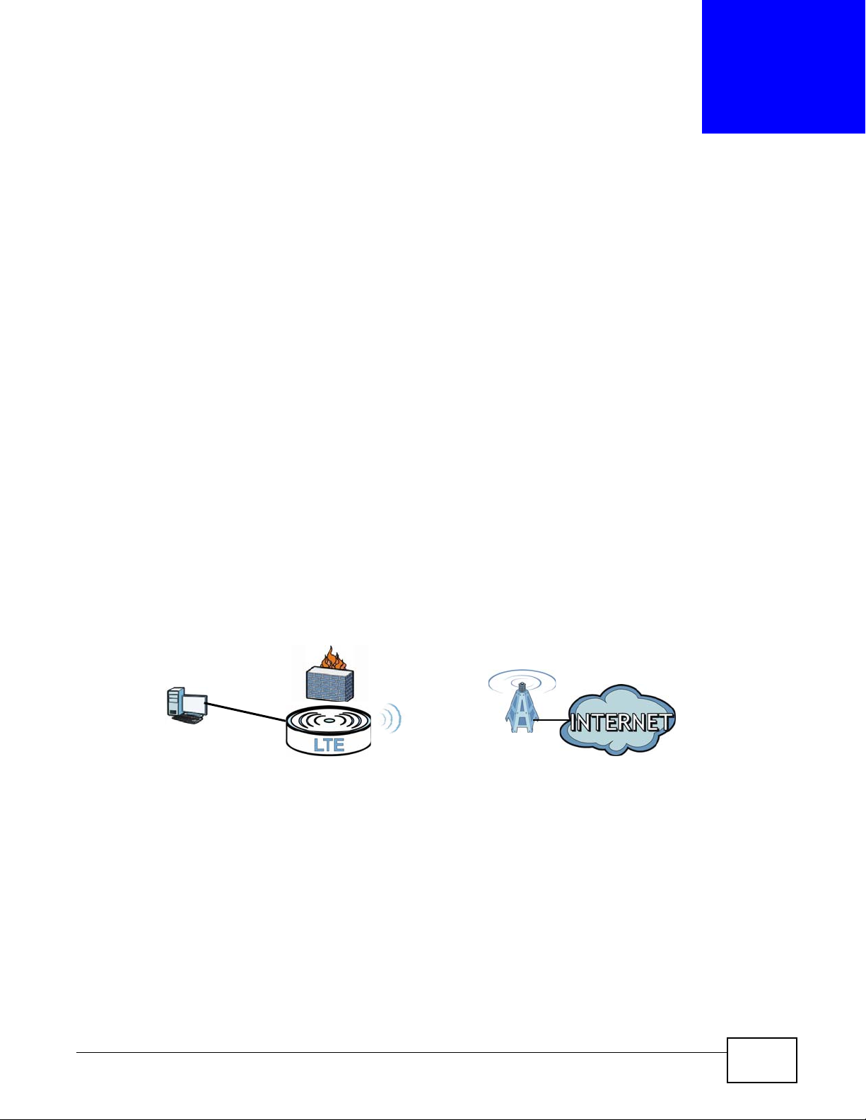
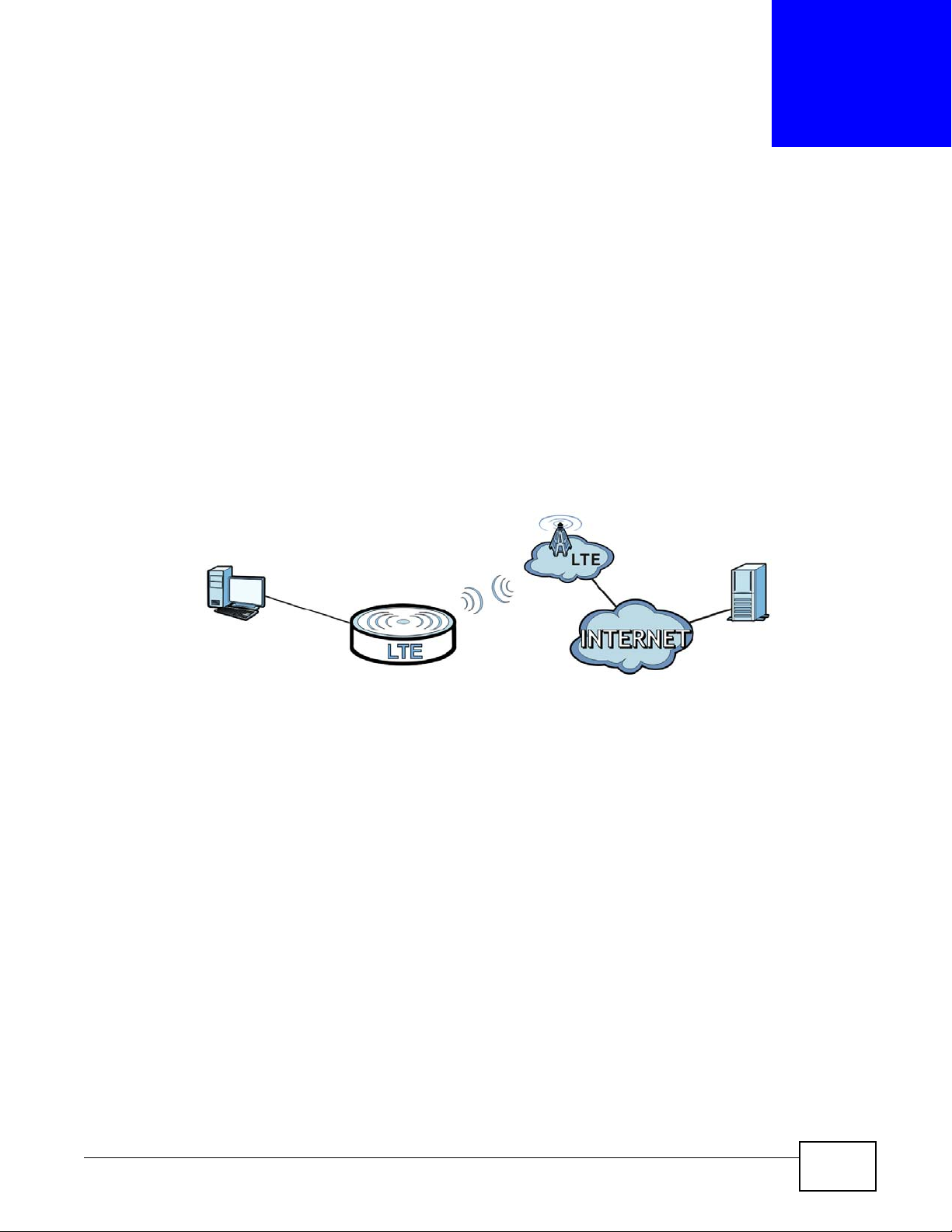
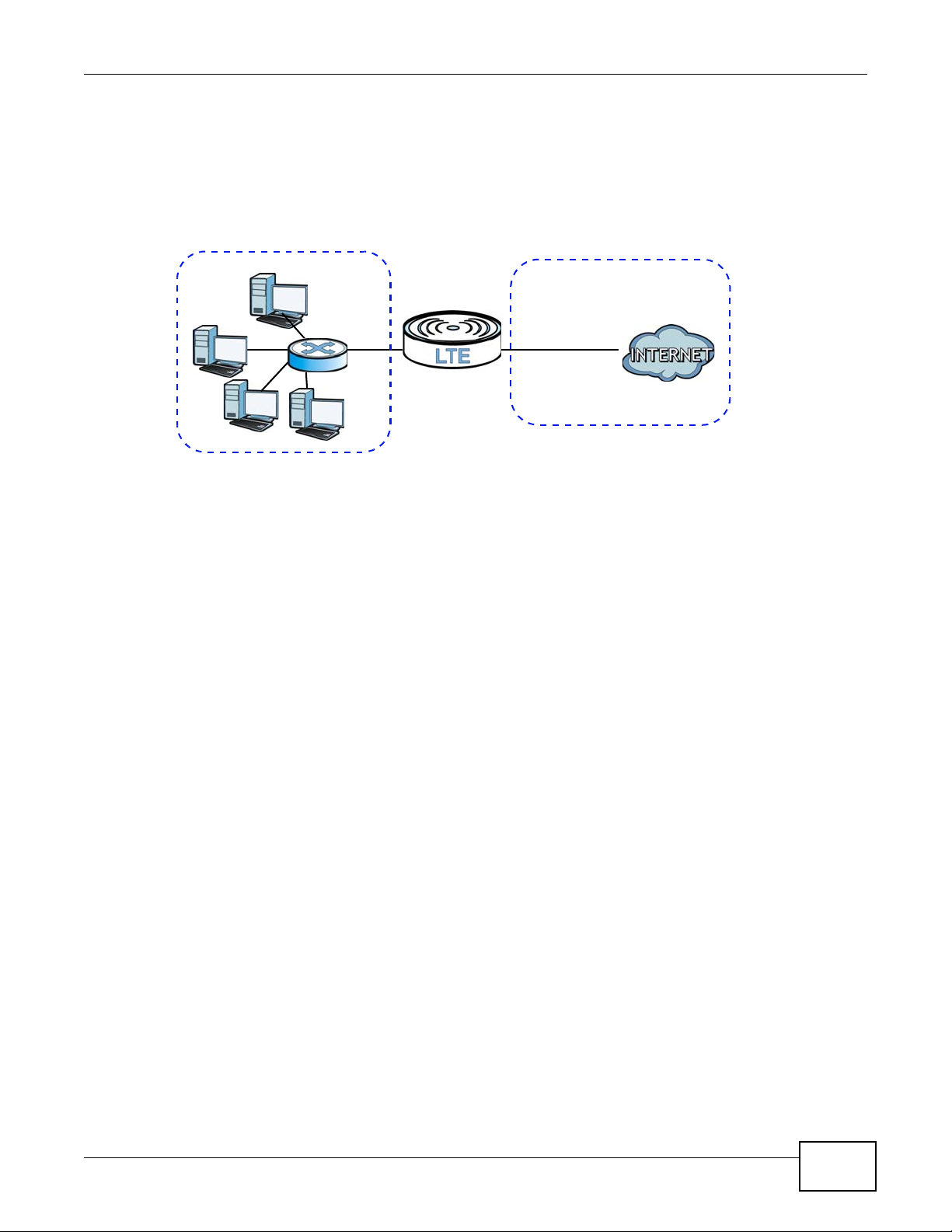
1.2.1 Internet Access
Your LTE Device provides shared Internet access by connecting to an LTE network. Computers can
connect to the LTE Device’s PoE injector.
Figure 1 LTE Device’s Internet Access Application
LTE7410 User’s Guide 13
Page 14
Chapter 1 Introduction
PSTN
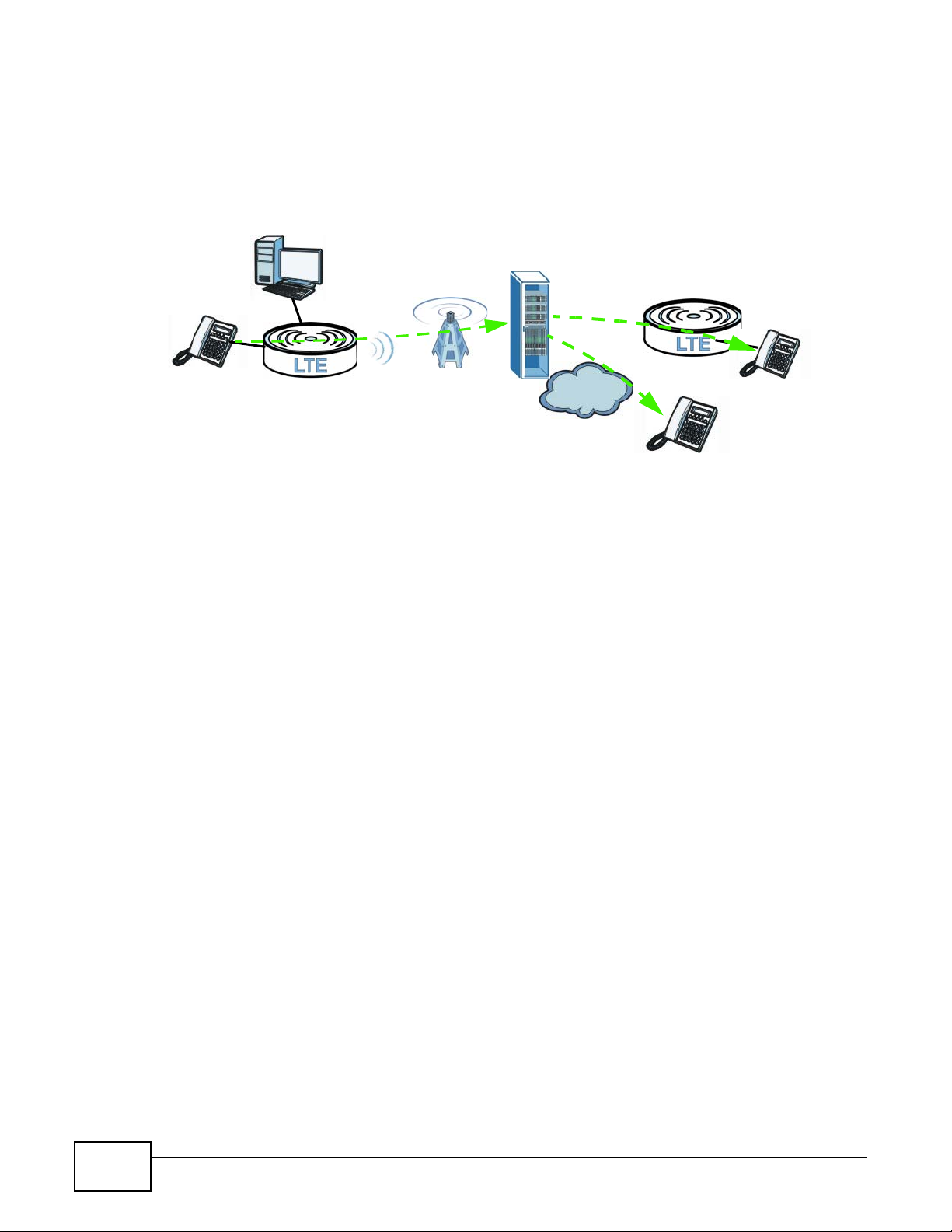
1.2.2 VoIP Features
Use SIP (Session Initiation Protocol) accounts with the LTE Device to make and receive VoIP
telephone calls.
Figure 2 LTE Device’s VoIP Application
The LTE Device sends your call to a VoIP service provider’s SIP server which forwards your calls
towards the destination VoIP or PSTN phones.
1.3 Ways to Manage the LTE Device
Use the following method to manage the LTE Device.
• Web Configurator. This is recommended for everyday management of the LTE Device using a
(supported) web browser.
1.4 Good Habits for Managing the LTE Device
Do the following things regularly to make the LTE Device more secure and to manage the LTE
Device more effectively.
• Change the password. Use a password that’s not easy to guess and that consists of different
types of characters, such as numbers and letters.
• Write down the password and put it in a safe place.
• Back up the configuration (and make sure you know how to restore it). Restoring an earlier
working configuration may be useful if the device becomes unstable or even crashes. If you
forget your password to access the Web Configurator, you will have to reset the LTE Device to its
factory default settings. If you backed up an earlier configuration file, you would not have to
totally re-configure the LTE Device. You could simply restore your last configuration. Keep in
mind that backing up a configuration file will not back up passwords used to set up VoIP. Write
down any information your ISP provides you.
14
LTE7410 User’s Guide
Page 15
2.1 Overview
The web configurator is an HTML-based management interface that allows easy device setup and
management via Internet browser. Use Internet Explorer 8.0 and later versions, Chrome 40 and
later versions, Mozilla Firefox 36 and later versions, or Safari 7.0 and later versions. The
recommended screen resolution is 1024 by 768 pixels.
In order to use the web configurator you need to allow:
• Web browser pop-up windows from your device. Web pop-up blocking is enabled by default in
Windows XP SP (Service Pack) 2.
• JavaScript (enabled by default).
• Java permissions (enabled by default).
CHAPTER 2
Introducing the Web Configurator
2.1.1 Accessing the Web Configurator
1 Make sure your LTE Device hardware is properly connected (refer to the Quick Start Guide).
2 Launch your web browser.
3 Type "192.168.1.1" as the URL.
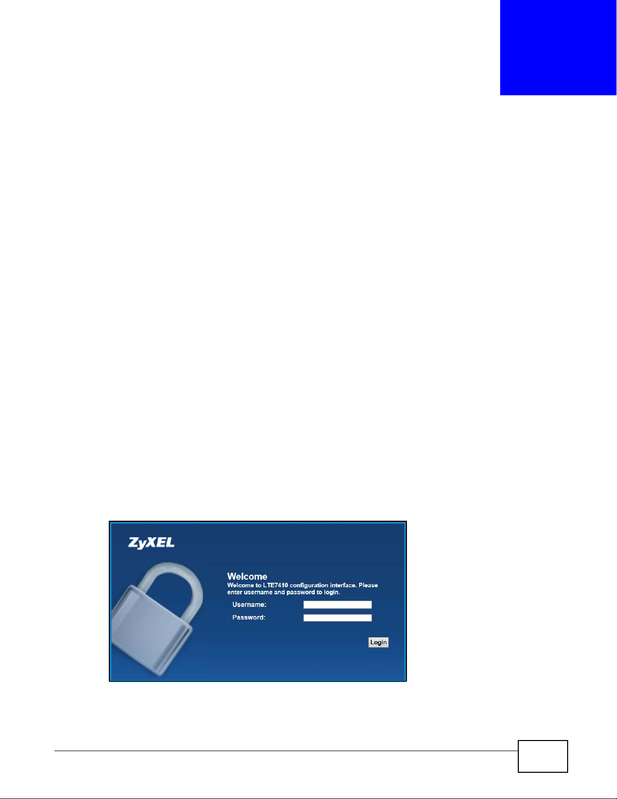
4 A password screen displays. Type “admin” as the default Username and “1234” as the default
password to access the device’s W eb Configur ator. Click Login. If you have changed the password,
enter your password and click Login.
Figure 3 Password Screen
Note: For security reasons, the LTE Device automatically logs you out if you do not use
the web configurator for five minutes (default). If this happens, log in again.
LTE7410 User’s Guide 15
Page 16
Chapter 2 Introducing the Web Configurator
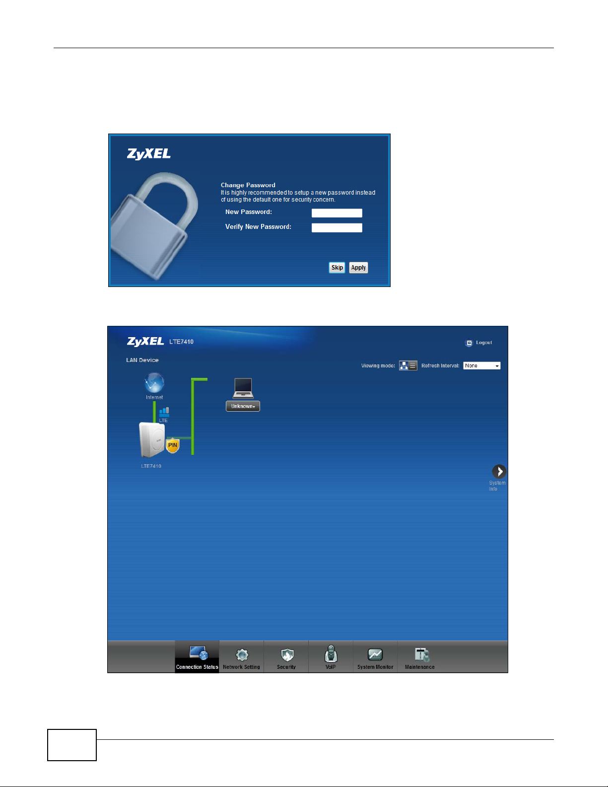
5 The following screen displays if you have not yet changed your password. It is strongly
recommended you change the default password. Enter a new password, retype it to confirm and
click Apply; alternatively click Skip to proceed to the main menu if you do not want to change the
password now.
Figure 4 Change Password Screen
6 The Connection Status screen appears.
Figure 5 Connection Status
7 Click System Info to display the System Info screen, where you can view the LTE Device’s
interface and system information.
16
LTE7410 User’s Guide
Page 17
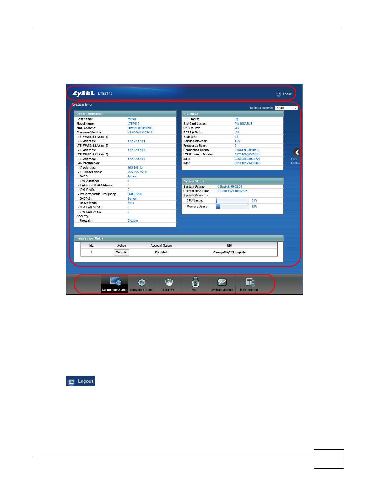
2.2 The Web Configurator Layout
B
A
C
Click Connection Status > System Info to show the following screen.
Figure 6 Web Configurator Layout
Chapter 2 Introducing the Web Configurator
As illustrated above, the main screen is divided into these parts:
• A - title bar
• B - main window
• C - navigation panel
2.2.1 Title Bar
The title bar shows the Logout icons in the upper right corner.
Click the Logout icon to log out of the web configurator.
LTE7410 User’s Guide
17
Page 18

Chapter 2 Introducing the Web Configurator
2.2.2 Main Window
The main window displays information and configuration fields. It is discussed in the rest of this
document.
Click LAN Device on the System Info screen (a in Figure 6 on page 17) to display the
Connection Status screen. See Chapter 3 on page 22 for more information on the System Info
and Connection Status screens.
18
LTE7410 User’s Guide
Page 19

PART II
Technical Reference
The appendices provide general information. Some details may not apply to your LTE Device.
19
Page 20

20
Page 21
CHAPTER 3
Connection Status and System Info
3.1 Overview
After you log into the web configurator, the Connection Status screen appears. This shows the
network connection status of the LTE Device and clients connected to it.
Use the System Info screen to look at the current status of the device, system resources,
interfaces (LAN and WAN), and SIP accounts. You can also register and unregister SIP accounts.
If you click Virtual Device on the System Info screen, a visual graphic appears, showing the
connection status of the LTE Device’s ports. See Section 2.2.2 on page 18 for more information.
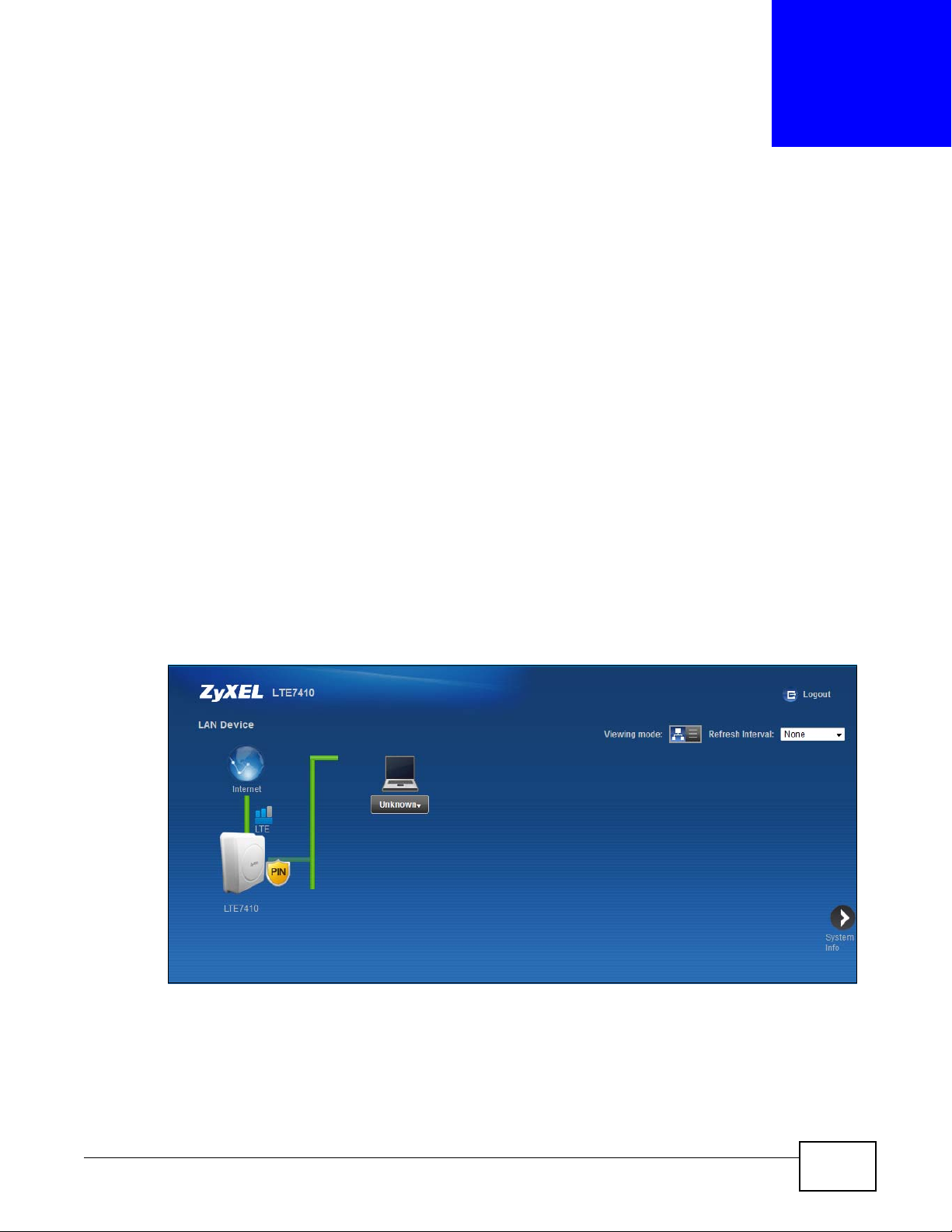
3.2 The Connection Status Screen
Use this screen to view the network connection status of the device and its clients. A warning
message appears if there is a connection problem. You can configure how often you want the LTE
Device to update this screen in Refresh Interval.
Figure 7 Connection Status: Icon View
LTE7410 User’s Guide 21
Page 22
Chapter 3 Connection Status and System Info
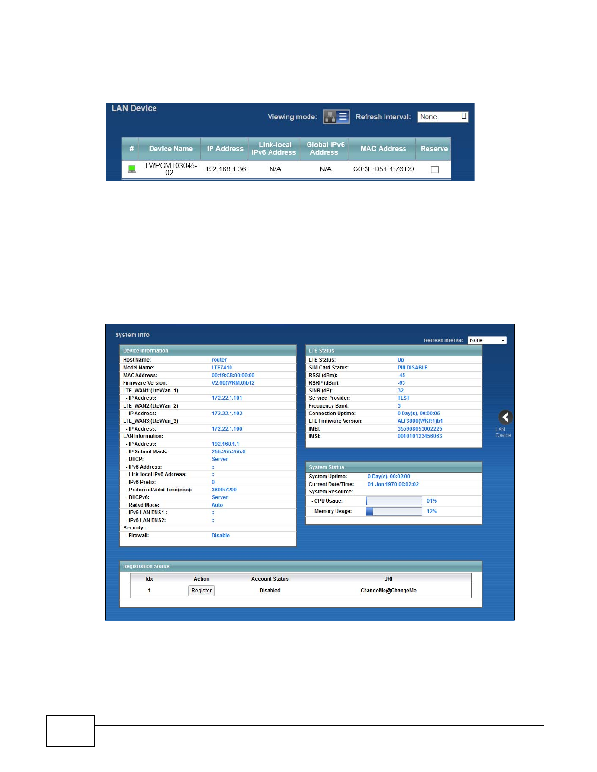
To view the connected LAN devices in a list, click List View in the Viewing mode selection box.
Figure 8 Connection Status: List View
In Icon View, if you want to view information about a client, click the client’s name and Info.
In List View, you can also view the client’s information.
3.3 The System Info Screen
Click Connection Status > System Info to open this screen.
Figure 9 System Info Screen
22
LTE7410 User’s Guide
Page 23

Chapter 3 Connection Status and System Info
Each field is described in the following table.
Table 1 System Info Screen
LABEL DESCRIPTION
Refresh Interval Select how often you want the LTE Device to update this screen from the drop-
Device Information
Host Name This field displays the L TE Dev ice system name. It is used for ide ntification. Y ou can
Model Name This is the model name of your device.
MAC Address This is the MAC (Media Access Control) or Ethernet address unique to your LTE
Firmware Version This field displays the current version of the firmware inside the device. It also
LTE_WAN1 ~
LTE_WAN3 - IP Address
LAN Information
IP Address This field displays the current IP address of the LTE Device in the LAN.
IP Subnet Mask This field displays the current subnet mask in the LAN.
DHCP This field displays what DHCP services the LTE Device is providing to the LAN:
down list box.
change this in the Maintenance > System screen’s Host Name field.
Device.
shows the date the firmware version was created. Go to the Maintenance >
Firmware Upgrade screen to change it.
This field displays the current LTE IP address of the LTE Device in the WAN.
Server - The LTE Device is a DHCP server in the LAN. It assigns IP addresses to
other computers in the LAN.
None - The LTE Device is not providing any DHCP services to the LAN.
IPv6 Address This is the current IPv6 address of the LTE Device in the LAN.
Link-local IPv6
Address
IPv6 Prefix This is the current IPv6 prefix length in the LAN.
Preferred/Valid Time
(sec)
DHCPv6 This field displays what DHCPv6 services the LTE Device is providing to the LAN:
Radvd Mode This shows the status of RADVD (Router Advertisement Daemon).
IPv6 LAN DNS1/
DNS2
Security
Firewall This shows whether or not the firewall is enabled (on).
LTE Status
LTE Status This displays 4G LTE UP for an LTE connection. Down displays when the LTE
This is the current LAN IPv6 link-local address of the LTE Device.
This is the preferred lifetime and valid lifetime in the LAN.
Server - The Device is a DHCPv6 server in the LAN. It assigns IP addresses to
other computers in the LAN.
None - The LTE Device is not providing any DHCPv6 services to the LAN.
This is the first/second DNS server IPv6 address the LTE Device passes to the DHCP
clients.
Device does not have a cellular connection.
LTE7410 User’s Guide
23
Page 24

Chapter 3 Connection Status and System Info
Table 1 System Info Screen (continued)
LABEL DESCRIPTION
SIM Card Status This displays the SIM card status:
PIN DISABLE - the SIM card has no PIN code security.
PIN REQUIRED - the SIM card has PIN code security, but you did not enter the
PIN code yet.
PIN VERIFIED - the SIM card ha s PIN code security, and you entered the correct
PIN code.
PIN locked - you entered an incorrect PIN code too many times, so the SIM card
has been locked; call the ISP for a PUK (Pin Unlock Key) to unlock the SIM card.
SIM ERROR - the LTE Device does not detect that there is a SIM card inserted.
RSSI (dBm) This displays the strength of the LTE connection that the LTE Device has with the
base station which is also known as eNodeB or eNB.
RSRP (dBm) This displays the LTE RSRP (Reference Signal Received Power).
SINR (dB) This displays the Signal to Interference plus Noise Ratio in dB.
Service Provider This displays the service provider’s name of the connected LTE network.
Frequency Band This displays the frequency band of the cellular connection. LTE displays for an L TE
Connection Uptime This displays how long the LTE connection has been availa ble since it was last
LTE Firmware
Version
IMEI This displays the LTE Device’s International Mobile Equipment Identity number
IMSI This displays the International Mobile Subscriber Identity (IMSI) of the installed
System Status
System UpTime This field displays how long the LTE Device has been running since it last started
Current Date/Time This field displays the current date and time in the L TE Device. You can change this
System Resource
CPU Usage This field displays what percentage of the LTE Device’s processing ability is
Memory Usage This field displays what percentage of the LTE Device’s memory is currently used.
Registration Status
Idx This is the index number of each SIP account in the LTE Device.
connection.
established successfully.
This displays the version of the firmware on the LTE module.
(IMEI). An IMEI is a unique ID used to identify a mobile device.
SIM card. An IMSI is a unique ID used to identify a mobile subscriber in a mobile
network.
up. The LTE Device starts up when you plug it in, when you restart it
(Maintenance > Reboot).
in Maintenance > Time Setting.
currently used. When this percentage is close to 100%, the LTE Device is running
at full load, and the throughput is not going to improv e anymore. If y ou want some
applications to have more throughput, you should turn off other applications.
Usually, this percentage should not increase much. If memory usage does get close
to 100%, the L TE Device i s probably becoming unstable, and y ou should restart the
device. See Chapter 22 on page 144, or turn off the device (unplug the power) for
a few seconds.
24
LTE7410 User’s Guide
Page 25

Chapter 3 Connection Status and System Info
Table 1 System Info Screen (continued)
LABEL DESCRIPTION
Action This field displays the current registration status of the SIP account. You have to
register SIP accounts with a SIP server to use VoIP.
If the SIP account is already registered with the SIP server,
•Click Unregister to delete the SIP account’s registration in the SIP server. This
does not cancel your SIP acco unt, but it deletes the mapping between your SIP
identity and your IP address or domain name.
• The second field displays Registered.
If the SIP account is not registered with the SIP server,
•Click Register to have the LTE Device attempt to register the SIP account with
the SIP server.
• The second field displays the reason the account is not registered.
Inactive - The SIP account is not active. You can activate it in VoIP > SIP > SIP
Settings.
Register Fail - The last time the LTE Device tried to register the SIP account with
the SIP server , the attempt failed. The LTE Device automatically tries to register the
SIP account when you turn on the LTE Device or when you activate it.
Account Status This shows Active when the SIP account ha s be en registered and ready for use or
In-Active when the SIP account is not yet registered.
URI This field displays the account number and service domain of the SIP account. You
can change these in VoIP > SIP > SIP Settings.
LTE7410 User’s Guide
25
Page 26

Chapter 3 Connection Status and System Info
26
LTE7410 User’s Guide
Page 27
4.1 Overview
WAN
LAN
This chapter discusses the LTE Device ’s Broadband screens. Use these screens to configure your
LTE Device for Internet access.
A WAN (Wide Area Network) connection is an outside connection to another network or the
Internet. It connects your private networks, such as a LAN (Local Area Network) and other
networks, so that a computer in one location can communicate with computers in other locations.
Figure 10 LAN and WAN
CHAPTER 4
Broadband
4.1.1 What You Can Do in this Chapter
•Use the Broadband screen to view or edit an L TE WAN interface. Y o u can also configure the W AN
settings on the LTE Device for Internet access (Section 4.2 on page 28).
•Use the SIM screen to enter the PIN of your SIM card (Section 4.3 on page 30).
4.1.2 What You Need to Know
The following terms and concepts may help as you read this chapter.
WAN IP Address
The WAN IP address is an IP address for the L TE Device, which makes it accessible from an outside
network. It is used by the LTE Device to communicate with other devices in other networks. The ISP
dynamically assigns it each time the LTE Device tries to access the Internet.
LTE7410 User’s Guide 27
Page 28
Chapter 4 Broadband
APN
Access Point Name (APN) is a unique string which indicates an LTE network. An APN is required for
LTE stations to enter the LTE network and then the Internet.
4.1.3 Before You Begin
You may need to know your Internet access settings such as LTE APN, WAN IP address and SIM
card’s PIN code if the INTERNET light on your LTE Device is off. Get this information from your
service provider.
4.2 The Broadband Screen
The LTE Device must have a WAN interface to allow users to use the LTE connection to access the
Internet. Use the Broadband screen to manage WAN interfaces.
Click Network Setting > Broadband. The following screen opens.
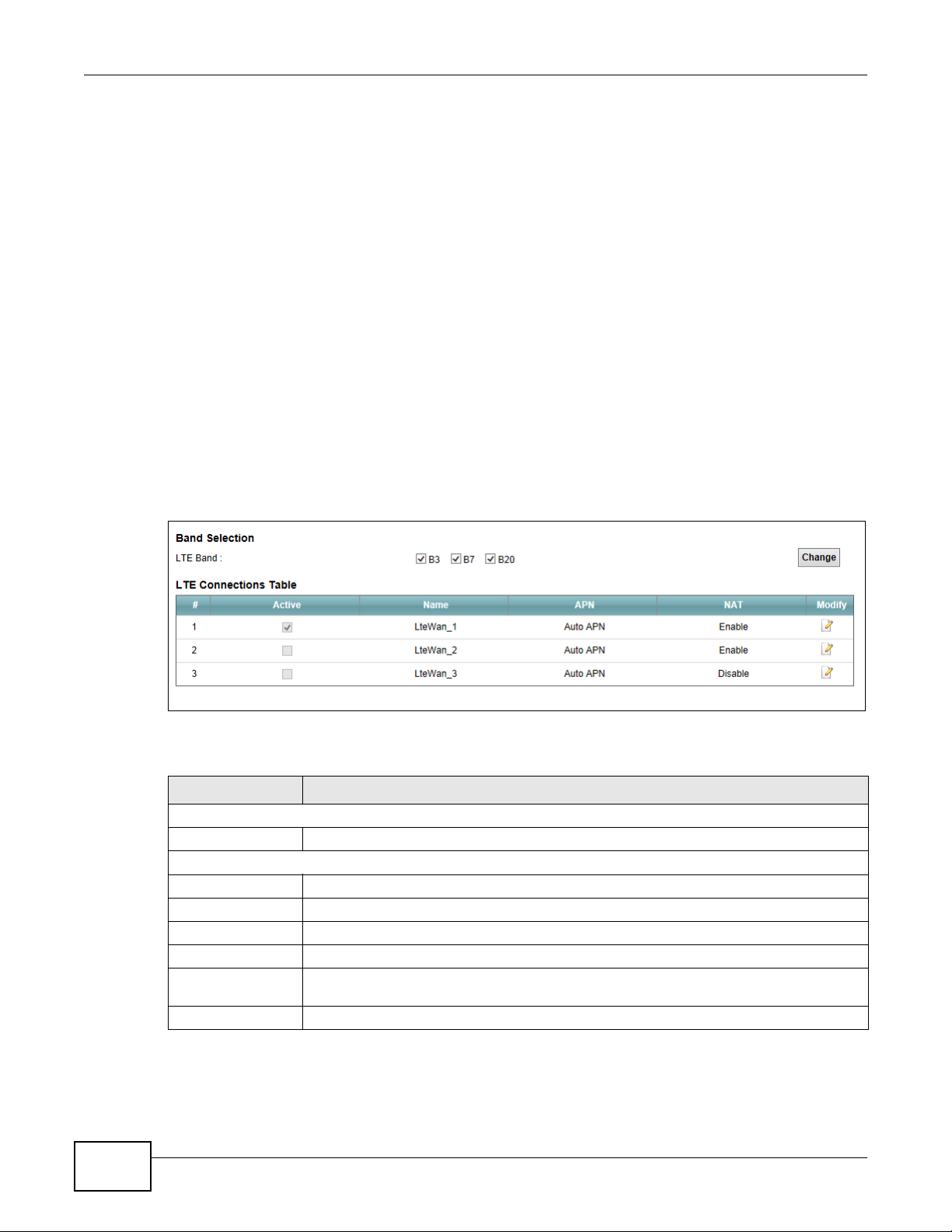
Figure 11 Network Setting > Broadband
28
The following table describes the fields in this screen.
Table 2 Network Setting > Broadband
LABEL DESCRIPTION
Band Selection
LTE Band Select the LTE bands to use for the LTE Device’s WAN connection.
LTE Connections Table
# This is the index number of the connection.
Active This shows whether the LTE connection is activated.
Name This is the service name of the connection.
APN This field displays the name of the LTE network to which the LTE Device connects.
NAT This shows whether NAT is activated or not for this connection. NAT is not available
when the connection uses the bridging service.
Modify Click the Edit icon to configure the connection.
LTE7410 User’s Guide
Page 29
4.2.1 Edit LTE Connection
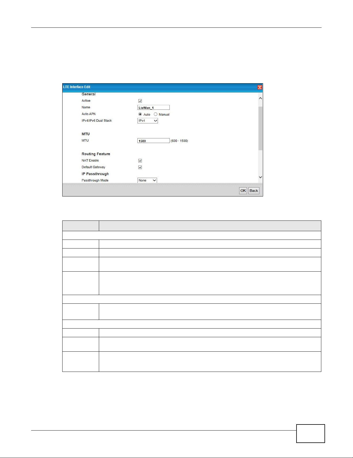
In Network Setting > Broadband, click the Edit icon next to an LTE connection to display the
following screen. Use this screen to configure an LTE WAN connection.
Figure 12 Network Setting > Broadband > LTE Interface Edit
Chapter 4 Broadband
The following table describes the fields in this screen.
Table 3 Network Setting > Broadband > LTE Interface Edit
LABEL DESCRIPTION
General
Active Select this to have the LTE Device use the LTE connection.
Name Specify the name for this WAN interface.
Auto APN Select Auto to have the LTE Device configure the APN (Acc ess P oint Name ) of an LTE network
automatically. Otherwise, select Manual and enter the APN manually in the field below.
IPv4/IPv6
Dual Stack
MTU
MTU
Routing Feature
NAT Enable Select this to activate NAT on this WAN interface.
Default
Gateway
IP
Passthrough
Select IPv4 if you want the LTE Device to run IPv4 only.
Select IPv6/IPv4 to allow the LTE Device to run IPv4 and IPv6 at the same time.
Select IPv6 if you want the LTE Device to run IPv6 only.
The Maximum Trans mi ssion Unit (MTU) defines the size of the largest packet allowed on an
interface or connection. Enter the MTU for this WAN interface in this field.
Select this option to have the LTE Device use the WAN interface of this connection as the
system default gateway.
IP Passthrough allows a LAN computer on the local netwo r k of the LTE Device to have access
to web services using the public IP address. When IP Passthrough is configured, all traffic is
forwarded to the computer and will not go through NAT.
LTE7410 User’s Guide
29
Page 30
Chapter 4 Broadband
Table 3 Network Setting > Broadband > LTE Interface Edit (continued)
LABEL DESCRIPTION
Passthrough
Mode
OK Click this to save your changes.
Back Click this to exit this screen without saving.
Select the Passthrough Mode for the LTE Device.
Select None to disable this feature.
Select Dynamic to allow the first connected LAN computer to have access to web services
using the public IP address.
Select Fixed to set the IP passthrough to a fix e d MA C address. This allows the LAN c omputer
with the MAC address specified in the Fixed Passthrough to fixed MAC field to have access
to web services using the public IP address.
4.3 SIM Screen
Use the SIM screen to enter the PIN of your SIM card.
Entering the wrong PIN code 3 times locks the SIM card after which you
need a PUK from the service provider to unlock it.
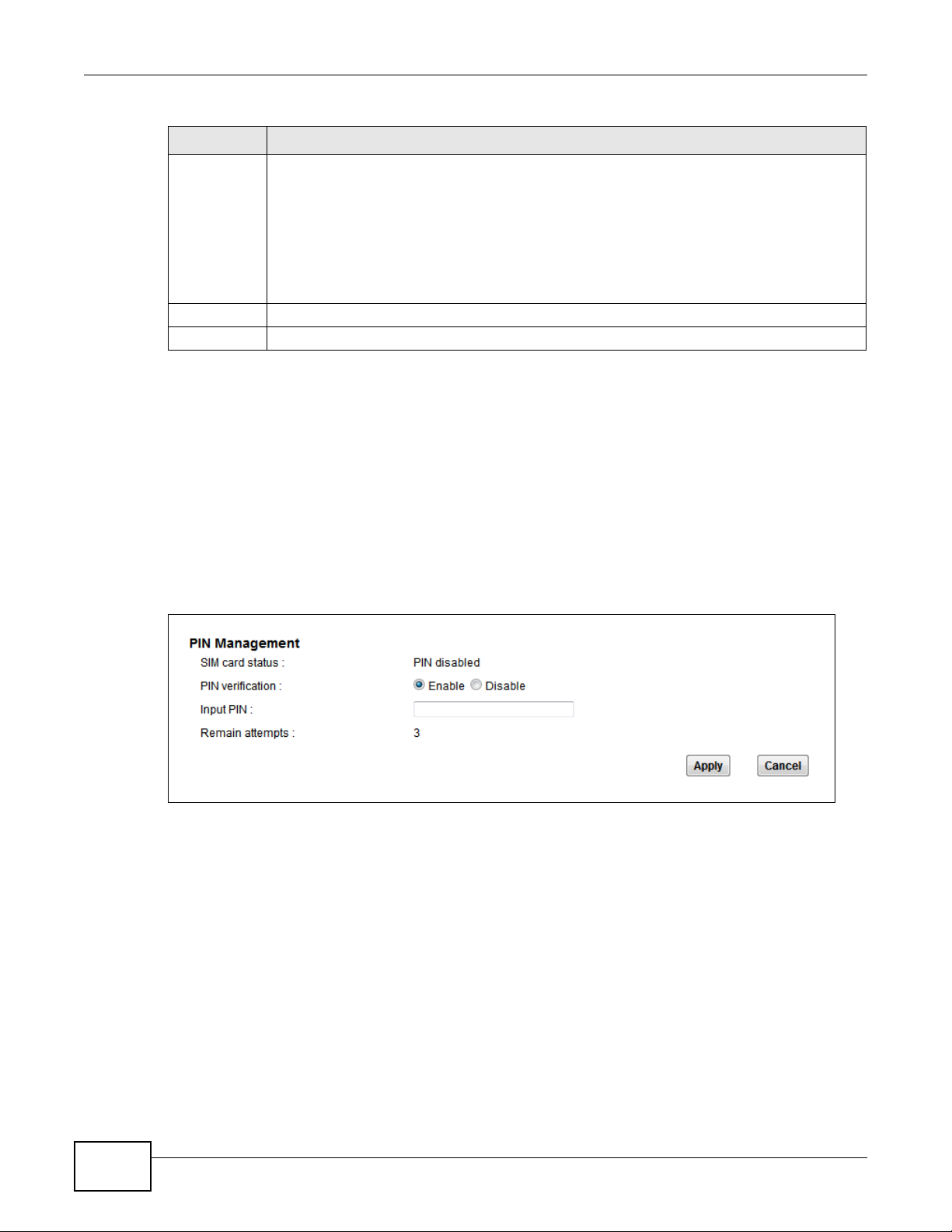
Click Network Setting > Broadband > SIM. The following screen opens.
Figure 13 Network Setting > Broadband > SIM
30
LTE7410 User’s Guide
Page 31

Chapter 4 Broadband
The following table describes the fields in this screen.
Table 4 Network Setting > Broadband > SIM
LABEL DESCRIPTION
SIM card
status
PIN
verification
Input PIN If you enabled PIN verification, enter the 4-digit PIN code (0000 for example) provided by
Remain
attempts
Apply Click Apply to save your changes.
Cancel Click Cancel to return to the previous screen without saving.
This displays the SIM card status:
PIN DISABLE - the SIM card has no PIN code security.
PIN REQUIRED - the SIM card has PIN code security, but you did not enter the PIN code yet.
PIN VERIFIED - the SIM card has PIN code security, and you entered the correct PIN code.
PIN locked - you entered an incorrect PIN code too many times, so the SIM card has been
locked; call the ISP for a PUK (Pin Unlock Key) to unlock the SIM card.
SIM ERROR - the LTE Device does not detect that there is a SIM card inserted.
A PIN (Personal Identification Number ) c ode i s a k ey to a 3G card. Wit hou t the PIN code, y o u
cannot use the 3G card.
Select Enable if the 3G service provider requires you to enter a PIN to use the SIM card.
Select Disable if the 3G service provider lets you use the SIM without inputting a PIN.
your ISP. If you enter the PIN code incorrectly too many times, the ISP may block your 3G SIM
card and not ley you use the account to access the Internet .
This is how many more times you can try to enter the PIN code before the ISP blocks your SIM
card.
4.3.1 PUK Code Screen
If the SIM card is locked, use this screen to enter the PUK (Pin Unlock Key) code.
Note: You may have to ask the service provider for a PUK code to unlock the SIM card.
LTE7410 User’s Guide
31
Page 32

Chapter 4 Broadband
Figure 14 PUK Code
You will need a new SIM card if you enter the wrong PUK code too many
times.
The following table describes the fields in this screen.
Table 5 PUK Code
LABEL DESCRIPTION
PUK code Enter the PUK (Pin Unlock Key) code to unlock the SIM card.
New PIN code Enter the new PIN code for the SIM card.
PUK remaining
authentication
times
Apply Click Apply to save your changes.
Cancel Click Cancel to return to the previous screen without saving.
This shows how many more times you can try to enter the PUK code before permanently
damaging the SIM card.
4.4 Technical Reference
The following section contains additional technical information about the LTE Device features
described in this chapter.
DNS Server Address Assignment
Use Domain Name System (DNS) to map a domain name to its corresponding IP address and vice
versa. The DNS server is ex tremely important be ca use without it, you m ust know the IP address of
a computer before you can access it.
32
The LTE Device can get the DNS server addresses in the following ways.
LTE7410 User’s Guide
Page 33

Chapter 4 Broadband
1 The ISP tells you the DNS server addresses, usually in the form of an information sheet, when you
sign up. If your ISP gives you DNS server addresses, manually enter them in the DNS server fields.
2 If your ISP dynamically assigns the DNS server IP addresses (along with the LTE Device’s WAN IP
address), set the DNS server fields to get the DNS server address from the ISP.
LTE7410 User’s Guide
33
Page 34

Chapter 4 Broadband
34
LTE7410 User’s Guide
Page 35

5.1 Overview
WAN
LAN
A Local Area Network (LAN) is a shared communication system to which many computers are
attached. A LAN is usually located in one immediate area such as a building or floor of a building.
The LAN screens can help you configure a LAN DHCP server and manage IP addresses.
CHAPTER 5
Home Networking
5.1.1 What You Can Do in this Chapter
•Use the LAN Setup screen to set the LAN IP address, subnet mask, and DHCP settings (Section
5.2 on page 37).
•Use the IPv6 LAN Setup screen to configure the IPv6 settings on your Device’s LAN interface
(Section 5.3 on page 38).
•Use the Static DHCP screen to assign IP addresses on the LAN to specific individual computers
based on their MAC Addresses (Section 5.4 on page 42).
•Use the UPnP screen to enable UPnP (Section 5.5 on page 44).
5.1.2 What You Need To Know
The following terms and concepts may help as you read this chapter.
5.1.2.1 About LAN
IP Address
Similar to the way houses on a street share a common street name, so too do computers on a LAN
share one common network number. This is known as an Internet Protocol address.
LTE7410 User’s Guide 35
Page 36

Chapter 5 Home Networking
Subnet Mask
The subnet mask specifies the network number portion of an IP address. Your LTE Device will
compute the subnet mask automatically based on the IP address that you entered. You don't need
to change the subnet mask computed by the LTE Device unless you are instructed to do otherwise.
DHCP
DHCP (Dynamic Host Configuration Protocol) allows clients to obtain TCP/IP configuration at startup from a server. This LTE Device has a built-in DHCP se rver capability that assigns IP addresses
and DNS servers to systems that support DHCP client capability.
DNS
DNS (Domain Name System) maps a domain name to its corresponding IP address and vice versa.
The DNS server is extremely important because without it, you must know the IP address of a
computer before you can access it. The DNS server addresses you enter when you set up DHCP are
passed to the client machines along with the assigned IP address and subnet mask.
5.1.2.2 About UPnP
How do I know if I'm using UPnP?
UPnP hardware is identified as an icon in the Network Connections folder (Windows XP). Each UPnP
compatible device installed on your network will appear as a separate icon. Selecting the icon of a
UPnP device will allow you to access the information and properties of that device.
Cautions with UPnP
The automated nature of NAT traversal applications in establishing their own services and opening
firewall ports may present network security issues. Network information and configur ation may also
be obtained and modified by users in some network environments.
When a UPnP device joins a network, it announces its presence with a multicast message. For
security reasons, the LTE Device allows multicast messages on the LAN only.
All UPnP-enabled devices may communicate freely with each other without additional configuration.
Disable UPnP if this is not your intention.
UPnP and ZyXEL
ZyXEL has achieved UPnP certification from the Universal Plug and Play Forum UPnP™
Implementers Corp. (UIC). ZyXEL's UPnP implementation supports Internet Gateway Device (IGD)
1.0.
36
See Section 5.7 on page 46 for examples of installing and using UPnP.
LTE7410 User’s Guide
Page 37

5.2 The LAN Setup Screen
Click Network Setting > Home Networking to open the LAN Setup screen. Use this screen to
set the Local Area Network IP address and subnet mask of your LTE Device and configure the DNS
server information that the LTE Device sends to the DHCP client devices on the LAN.
Figure 15 Network Setting > Home Networking > LAN Setup
Chapter 5 Home Networking
The following table describes the fields in this screen.
Table 6 Network Setting > Home Networking > LAN Setup
LABEL DESCRIPTION
LAN IP Setup
IP Address Enter the LAN IP address you want to assign to your LTE Device in dotted decimal
notation, for example, 192.168.1.1 (factory default).
Subnet Mask Type the subnet mask of your network in dotted decimal notation, for example
DHCP Server State
DHCP Select Enable to have your LTE Device assign IP addresses, an IP default gateway and
IP Addressing Values
255.255.255.0 (factory default). Your LTE Device automatically computes the subnet
mask based on the IP address you enter, so do not change this field unless you are
instructed to do so.
DNS servers to LAN computers and other devices that are DHCP clients.
If you select Disable, you need to manually configure the IP addresses of the
computers and other devices on your LAN.
If you select DHCP Relay, the LTE Device acts as a surrogate DHCP server and relays
DHCP requests and responses between the remote server and the clients. Enter the IP
address of the actual, remote DHCP server in the Remote DHCP Server field in this
case.
When DHCP is used, the following fields need to be set:
LTE7410 User’s Guide
37
Page 38

Chapter 5 Home Networking
Table 6 Network Setting > Home Networking > LAN Setup (continued)
LABEL DESCRIPTION
IP Pool Starting
Address
Pool Size This field specifies the size, or count of the IP address pool.
DHCP Server Lease Time
Lease Time DHCP server leases an address to a new device for a period of time, called the DHCP
DNS Values
DNS Server 1-2 The LTE Device supports DNS proxy by default. The LTE Device sends out its own LAN IP
Apply Click Apply to save your changes.
Cancel Click Cancel to restore your previously saved settings.
This field specifies the first of the contiguous addresses in the IP address pool.
lease time. When the lease expires, the DHCP server might assign the IP address to a
different device.
address to the DHCP clients as the first DNS server address. DHCP clients use this first
DNS server to send domain-name queries to the LTE Device. The LTE Device sends a
response directly if it has a record of the domain-name to IP address mapping. If it does
not, the LTE Device queries an outside DNS server and relays the response to the DHCP
client.
Select Obtained From ISP if your ISP dynamically assigns DNS server information
(and the LTE Device's WAN IP address).
Select UserDefined if you have the IP address of a DNS server. Enter the DNS server's
IP address in the field to the right.
Select DNS Proxy to have the DHCP clients use the LTE Device’s own LAN IP address .
The LTE Device works as a DNS relay.
Select None to not configure extra DNS servers.
5.3 The IPv6 LAN Setup Screen
Use this screen to configure the IPv6 settings for your LTE Device’s LAN interface.
38
LTE7410 User’s Guide
Page 39

Figure 16 Network Setting > Home Networking > IPv6 LAN Setup
Chapter 5 Home Networking
LTE7410 User’s Guide
39
Page 40

Chapter 5 Home Networking
The following table describes the labels in this screen.
Table 7 Network Setting > Home Networking > IPv6 LAN Setup
LABEL DESCRIPTION
IPv6 LAN Setup
Link Local Address
Type
IPv6 Address If you selected Manual in the Link Local Address Type field, enter the LAN IPv6
Prefix Enter the address prefix to specify how many most significant bits in an IPv6 address
MLD Snooping Multicast Listener Discovery (MLD) allows an IPv6 switch or router to discover the
Lan Global Identifier
Type
Lan Identifier If you selected Manual, enter the LAN Identifier in this field. The LAN identifi er should
IPv6 ULA Address
Type
IPv6 ULA Address If Manual is selected in the IPv6 ULA Address Type field, enter the IPv6 address
LAN IPv6 Address Setting
Delegate prefix from
WAN
Static Select this option to configure a fixed IPv6 address for the LTE Device’s LAN IPv6
Static IPv6 Address
Prefix
Prefix length If you select static IPv6 address, enter the IPv6 prefix length that the LTE Device uses
Preferred Lifetime Enter the preferred lifetime for the prefix.
Valid Lifetime Enter the valid lifetime for the prefix.
Select Manual to manually enter a link local address. Select EU I64 to use the EUI-64
format to generate a link local address from the Ethernet MAC address.
address you want to assign to your LTE Device in hexadecimal notation, for example,
fe80::1 (factory default).
compose the network address.
presence of MLD hosts who wish to receive multicast packets and the IP addresses of
multicast groups the hosts want to join on its network. Select Enabled to activate
MLD snooping on the LTE Device. This allows the LTE Device to check MLD packets
passing through it and learn the multic ast group membership. It helps reduce
multicast traffic.
Select Manual to manually enter a LAN identifier as the interface ID to identify the
LAN interface. The LAN Identifier is appended t o the IPv6 address pr efix to cre ate the
routable global IPv6 address. Select EUI64 to use the EUI-64 format to generate an
interface ID from the Ethernet MAC address.
be unique and 64 bits in hexadecimal form. Every 16 bit block should be separated by
a colon as in XXXX:XXXX:XXXX:XXXX where X is a hexadecimal character. Blocks of
zeros can be represented with double colons as in XXXX:XXXX::XXXX.
A unique local address (ULA) is a unique IPv6 address for use in private networks but
not routable in the global IPv6 Internet.
Select Auto Generate to have the Device automatically generate a globally unique
address for the LAN IPv6 address. Select Manual to enter a static IPv6 ULA address.
The address format is like fdxx:xxxx:xxxx:xxxx::/64.
prefix that the LTE Device uses for the LAN IPv6 address.
Select this option to automatically obtain an IPv6 network prefix from the service
provider or an uplink router.
address.
If you select static IPv6 address, enter the IPv6 address prefix that the LTE Device
uses for the LAN IPv6 address.
to generate the LAN IPv6 address.
An IPv6 prefix length specifies how many most significant bits (starting from the left)
in the address compose the network address. This field displays the bit number of the
IPv6 subnet mask.
40
LTE7410 User’s Guide
Page 41

Chapter 5 Home Networking
Table 7 Network Setting > Home Networking > IPv6 LAN Setup (continued)
LABEL DESCRIPTION
LAN IPv6 Address
Assign Setup
LAN IPv6 DNS Assign
Setup
DHCPv6
DHCPv6 Server Use this field to Enable or Disable DHCPv6 server on the LTE Device.
DNSv6 Mode Select the DNS role ( Proxy or Relay) that you want the LTE Device to act in the IPv6
Primary DNS This field is available if you choose Manual as the DNSv6 mode. Enter the first DNS
Secondary DNS This field is available if you choose Manual as the DNSv6 mode. Enter the second DNS
Information refresh
time
Advanced Setup Click this to open the IPv6 LAN Setup Advanced Setup section.
RADVD Setup
Send RA on Select this to have the LTE Device send router advertisement messages to the LAN
Select how you want to obtain an IPv6 address:
• Stateless: The LTE De vice uses IPv6 stateless autoconfiguration. RADVD (Router
Advertisement Daemon) is enabled to have the LTE Device send IPv6 prefix
information in router advertisements periodically and in response to router
solicitations. DHCPv6 server is disabled.
• Stateful: The LTE Device uses IPv6 stateful autoconfiguration. The DHCPv6 server
is enabled to have the LTE Device act as a DHCPv6 server and pass IPv6 addresses
to DHCPv6 clients.
• Stateless and Stateful: The LTE Device uses both IPv6 stateless and stateful
autoconfiguration. The LAN IPv6 clients can obtain IPv6 addresses either through
router advertisements or through DHCPv6.
Select how the LTE Device provide DNS server and domain name information to the
clients:
• Stateless: The LTE De vice uses IPv6 stateless autoconfiguration. RADVD (Router
Advertisement Daemon) is enabled to have the LTE Device send IPv6 prefix
information in router advertisements periodically and in response to router
solicitations. DHCPv6 server is disabled.
• Stateful: The LTE Device uses IPv6 stateful autoconfiguration. The DHCPv6 server
is enabled to have the LTE Device act as a DHCPv6 server and pass IPv6 addresses
to DHCPv6 clients.
• Stateless and Stateful: The LTE Device uses both IPv6 stateless and stateful
autoconfiguration. The LAN IPv6 clients can obtain IPv6 addresses either through
router advertisements or through DHCPv6.
LAN network. Alternatively, select Manual and specify IPv6 addresses of the DNS
servers in the fields below.
server IPv6 address the LTE Device passes to the DHCP clients.
server IPv6 address the LTE Device passes to the DHCP clients.
Enter the number of seconds a DHCPv6 client should wait before refreshing
information retrieved from DHCPv6.
hosts.
Router advertisement is a response to a router solicitation or a periodical multicast
advertisement from a router to advertise its presence and other parameters, such as
IPv6 prefix and DNS information.
Router solicitation is a request from a host to locate a router that can act as the
default router and forward packets.
Delegate M/O flag
from WAN
Manual Select this to specify the M/O flag setting manually.
Managed config
flag on
LTE7410 User’s Guide
Note: The LAN hosts neither generate global IPv6 addresses nor communicate with
other networks if you disable this feature.
Select this to have the LTE Device obtain the M/O (Managed/Other) flag setting from
the service provider or uplink router.
Select this to have the LTE Device indicate to hosts to obtain network settings (such as
prefix and DNS settings) through DHCPv6.
Clear this to have the LTE Device indicate to hosts that DHCPv6 is not available and
they should use the prefix in the router advertisement message.
41
Page 42

Chapter 5 Home Networking
Table 7 Network Setting > Home Networking > IPv6 LAN Setup (continued)
LABEL DESCRIPTION
Other config flag onSelect this to have the LTE Device indicate to hosts to o btain DNS inform ation throu gh
Advertisement
interval option on
Hop limit Enter the maximum number of network segments that a packet can cross before
Router Lifetime Enter the time in seconds that hosts should consider the LTE Device to be the default
Router Preference Select the router preference (Low, Medium or High) for the LTE Device. The LTE
Reachable Time (ms) Enter the time in milliseconds that can elapse before a neighbor is detected. Possible
Retrans Timer (ms) Enter the time in mill iseconds between neighbor solicitation packet retransmissions.
RA Interval Enter the time in seconds between router advertisement messages. Possible values for
Delegate MTU from
WAN
Manual Select this to specify the MTU manually.
MTU The Maximum T r ansmission Unit. Type the maximum size of each IPv6 data packet, in
DAD attempts Specify the number of DAD (Duplicate Address Detection) attempts before an IPv6
Apply Click this to save your changes.
Cancel Click this to restore your previously saved settings.
Advanced Setup Click this to close the IPv6 LAN Setup Advanced Setup section.
DHCPv6.
Clear this to have the LTE Device indicate to hosts that DNS information is not
available in this network.
Select this to have the Router Advertisement messages the LTE Device sends specify
the allowed interval between Router Advertisement messages.
reaching the destination. When forwarding an IPv6 packet, IPv6 routers are required
to decrease the hop limit by 1 and to discard the IPv6 packet when the Hop Limit is 0.
Possible values for this field are 0-255.
router. Possible values for this field are 0-9000.
Device sends this preference in the router advertisements to tell hosts what
preference they should use for the LTE Device. This helps hosts to choose their default
router especially when there are multiple IPv6 routers in the network.
Note: Make sure the hosts also support router preference to make this function work.
values for this field are 0-3600000.
Possible values for this field are 1000-4294967295.
this field are 4-1800.
Select this to have the LTE Device obtain the MTU setting from the service provider or
uplink router.
bytes, that can move through this interface. If a larger packet arrives, the L TE Device
divides it into smaller fragments.
address is assigned to the LTE Device LAN interface. Possible values for this field are
1-7.
5.4 The Static DHCP Screen
This table allows you to assign IP addresses on the LAN to specific individual computers based on
their MAC Addresses.
Every Ethernet device has a unique MAC (Media Access Control) address. The MAC address is
assigned at the factory and consists of six pairs of hexadecimal characters, for example,
00:A0:C5:00:00:02.
42
LTE7410 User’s Guide
Page 43

5.4.1 Before You Begin
Find out the MAC addresses of your network devices if you intend to add them to the Static DHCP
screen.
Use this screen to change your LTE Device’ s static DHCP settings. Click Network Setting > Home
Networking > Static DHCP to open the following screen.
Figure 17 Network Setting > Home Networking > Static DHCP
The following table describes the labels in this screen.
Table 8 Network Setting > Home Networking > Static DHCP
LABEL DESCRIPTION
Add new static
lease
# This is the index number of the entry.
Active
MAC Address The MAC (Media Access Control) or Ethernet address on a LAN (Local Area Network) is
Click this to add a new static DHCP entry.
unique to your computer (six pairs of hexadecimal notation).
Chapter 5 Home Networking
A network interface card such as an Ethernet adapter has a hardwired address that is
assigned at the factory. This address follows an industry standard that ensures no other
adapter has a similar address.
IP Address This field displays the IP address relative to the # field listed above.
Modify Click the Edit icon to configure the connection.
If you click Add new static lease in the Static DHCP screen, the following screen displays.
Figure 18 Static DHCP: Add New Static Lease
The following table describes the labels in this screen.
Table 9 Static DHCP: Add New Static Lease
LABEL DESCRIPTION
MAC Address Enter the MAC address of a computer on your LAN.
IP Address Enter the IP address that you want to assign to the computer on your LAN with the MAC
address that you will also specify.
LTE7410 User’s Guide
43
Page 44

Chapter 5 Home Networking
Table 9 Static DHCP: Add New Static Lease
LABEL DESCRIPTION
OK Click Apply to save your changes.
Cancel Click Cancel to exit this screen without saving.
5.5 The UPnP Screen
Universal Plug and Play (UPnP) is a distributed, open networking standard that uses TCP/IP for
simple peer-to-peer network connectivity between devices. A UPnP device can dynamically join a
network, obtain an IP address, convey its capabilities and learn about other devices on the network.
In turn, a device can leave a network smoothly and automatically when it is no longer in use.
See page 46 for more information on UPnP.
Use the following screen to configure the UPnP settings on your LTE Device. Click Network Setting
> Home Networking > Static DHCP > UPnP to display the screen shown next.
Figure 19 Network Setting > Home Networking > UPnP
The following table describes the labels in this screen.
Table 10 Network Settings > Home Networking > UPnP
LABEL DESCRIPTION
UPnP Select Enable to activate UPnP. Be aware that anyone could use a UPnP application to
Apply Click Apply to save your changes.
Cancel Click this to restore your previously saved settings.
open the web configurator's login screen without entering the LTE Device's IP address
(although you must still enter the password to access the web configurator).
5.6 Technical Reference
This section provides some technical background information about the topics covered in this
chapter.
44
LTE7410 User’s Guide
Page 45
Chapter 5 Home Networking
WAN
LAN
LANs, WANs and the LTE Device
The actual physical connection determines whether the LTE Device ports are LAN or WAN ports.
There are two separate IP networks, one inside the LAN network and the other outside the WAN
network as shown next.
Figure 20 LAN and WAN IP Addresses
DHCP Setup
DHCP (Dynamic Host Configuration Protocol, RFC 2131 and RFC 2132) allows individual clients to
obtain TCP/IP configuration at start-up from a server. You can configure the LTE Device as a DHCP
server or disable it. When configured as a server, the LTE Device provides the TCP/IP configuration
for the clients. If you turn DHCP service off, you must have another DHCP server on your LAN, or
else the computer must be manually configured.
IP Pool Setup
The LTE Device is pre-configured with a pool of IP addresses for the DHCP clients (DHCP Pool). See
the product specifications in the appendices. Do not assign static IP addresses from the DHCP pool
to your LAN computers.
LAN TCP/IP
The LTE Device has built-in DHCP server capability that assigns IP addresses and DNS servers to
systems that support DHCP client capability.
IP Address and Subnet Mask
Similar to the way houses on a street share a common street name, so too do computers on a LAN
share one common network number.
Where you obtain your network number depends on your particular situation. If the ISP or your
network administrator assigns you a block of registered IP addresses, follow their instructions in
selecting the IP addresses and the subnet mask.
If the ISP did not explicitly give you an IP network number, then most likely you have a single user
account and the ISP will assign you a dynamic IP address when the connection is established. If this
is the case, it is recommended that you select a network number from 192.168.0.0 to
192.168.255.0 and you must enable the Network Address Translation (NAT) feature of the LTE
LTE7410 User’s Guide
45
Page 46

Chapter 5 Home Networking
Device. The Internet Assigned Number Authority (IANA) reserved this block of addresses
specifically for private use; please do not use any other number unless you are told otherwise. Let's
say you select 192.168.1.0 as the network number; which covers 254 individual addresses, from
192.168.1.1 to 192.168.1.254 (zero and 255 are reserved). In other words, the first three numbers
specify the network number while the last number identifies an individual computer on that
network.
Once you have decided on the network number, pick an IP address that is easy to remember, for
instance, 192.168.1.1, for your LTE Device, but make sure that no other device on your network is
using that IP address.
The subnet mask specifies the network number portion of an IP address. Your LTE Device will
compute the subnet mask automatically based on the IP address that you entered. You don't need
to change the subnet mask computed by the LTE Device unless you are instructed to do otherwise.
Private IP Addresses
Every machine on the Internet must have a unique address. If your networks are isolated from the
Internet, for example, only between your two branch offices, you can assign any IP addresses to
the hosts without problems. However, the Internet Assigned Numbers Authority (IANA) has
reserved the following three blocks of IP addresses specifically for private networks:
• 10.0.0.0 — 10.255.255.255
• 172.16.0.0 — 172.31.255.255
• 192.168.0.0 — 192.168.255.255
You can obtain your IP address from the IANA, from an ISP or it can be assigned from a private
network. If you belong to a small organization and your Internet access is through an ISP, the ISP
can provide you with the Internet addresses for your local networks. On the other hand, if you are
part of a much larger organization, you should consult your network administrator for the
appropriate IP addresses.
Note: Regardless of your particular situation, do not create an arbitrary IP address;
always follow the guidelines above. For more information on address assignment,
please refer to RFC 1597, “Address Allocation for Private Internets” and RFC 1466,
“Guidelines for Management of IP Address Space”.
5.7 Installing UPnP in Windows Example
This section shows how to install UPnP in Windows Me and Windows XP.
Installing UPnP in Windows Me
Follow the steps below to install the UPnP in Windows Me.
1 Click Start and Control Panel. Double-click Add/Remove Programs .
46
LTE7410 User’s Guide
Page 47

Chapter 5 Home Networking
2 Click the Windows Setup tab and select Communication in the Components selection box. Click
Details.
Figure 21 Add/Remove Programs: Windows Setup: Communication
3 In the Communications window, select the Universal Plug and Play check box in the
Components selection box.
Figure 22 Add/Remove Programs: Windows Setup: Communication: Components
4 Click OK to go back to the Add/Remove Programs Properties window and click Next.
LTE7410 User’s Guide
47
Page 48

Chapter 5 Home Networking
5 Restart the computer when prompted.
Installing UPnP in Windows XP
Follow the steps below to install the UPnP in Windows XP.
1 Click Start and Control Panel.
2 Double-click Network Connections.
3 In the Network Connections window, click Advanced in the main menu and select Optional
Networking Components ….
Figure 23 Network Connections
4 The Windows Optional Networking Components Wizard window displays. Select Networking
Service in the Components selection box and click Details.
Figure 24 Windows Optional Networking Components Wizard
48
LTE7410 User’s Guide
Page 49

Chapter 5 Home Networking
5 In the Networking Services window, select the Universal Plug and Play check box.
Figure 25 Networking Services
6 Click OK to go back to the Windows Optional Networking Component Wizard window and
click Next.
5.8 Using UPnP in Windows XP Example
This section shows you how to use the UPnP feature in Windows XP. You must already have UPnP
installed in Windows XP and UPnP activated on the LTE Device.
Make sure the computer is connected to a LAN port of the LTE Device. Turn on your computer and
the LTE Device.
Auto-discover Your UPnP-enabled Network Device
1 Click Start and Control Panel. Double-click Network Connections. An icon displays under
Internet Gateway.
LTE7410 User’s Guide
49
Page 50

Chapter 5 Home Networking
2 Right-click the icon and select Properties.
Figure 26 Network Connections
3 In the Internet Connection Properties window, click Settings to see the port mappings there
were automatically created.
Figure 27 Internet Connection Properties
50
LTE7410 User’s Guide
Page 51

Chapter 5 Home Networking
4 You may edit or delete the port mappings or click Add to manually add port mappings.
Figure 28 Internet Connection Properties: Advanced Settings
Figure 29 Internet Connection Properties: Advanced Settings: Add
5 When the UPnP-enabled device is disconnected from your computer, all port mappings will be
deleted automatically.
LTE7410 User’s Guide
51
Page 52

Chapter 5 Home Networking
6 Select Show icon in notification area when connected option and click OK. An icon displays in
the system tray.
Figure 30 System Tr ay Icon
7 Double-click on the icon to display your current Internet connection status.
Figure 31 Internet Connection Status
Web Configurator Easy Access
With UPnP, you can access the web-based configurator on the L TE Device without finding out the IP
address of the LTE Device first. This comes helpful if you do not know the IP address of the LTE
Device.
Follow the steps below to access the web configurator.
1 Click Start and then Control Panel.
2 Double-click Network Connections.
52
LTE7410 User’s Guide
Page 53

3 Select My Network Places under Other Places.
Figure 32 Network Connections
Chapter 5 Home Networking
4 An icon with the description for each UPnP-enabled device displays under Local Network.
LTE7410 User’s Guide
53
Page 54

Chapter 5 Home Networking
5 Right-click on the icon for your LTE Device and select Invoke. The web configurator login screen
displays.
Figure 33 Network Connections: My Network Places
6 Right-click on the icon for your LTE Device and select Properties. A properties window displays
with basic information about the LTE Device.
Figure 34 Network Connections: My Network Places: Properties: Example
54
LTE7410 User’s Guide
Page 55

6.1 Overview
WAN
R1
R2
A
R3
LAN
The LTE Device usually uses the default gateway to route outbound traffic from computers on the
LAN to the Internet. To have the LTE Device send data to devices not reachable through the default
gateway, use static routes.
For example, the next figure shows a computer (A) connected to the LTE Device’s LAN interface.
The L TE Device routes most tr affic from A to the Internet through the LTE Device’s default gatew ay
(R1). You create one static route to connect to services offered by your ISP behind router R2. You
create another static route to communicate with a separate network behind a router R3 connected
to the LAN.
Figure 35 Example of Static Routing Topology
CHAPTER 6
Static Route
LTE7410 User’s Guide 55
Page 56

Chapter 6 Static Route
6.2 Configuring Static Route
Use this screen to view and configure IP static routes on the LTE Device. Click Network Setting >
Routing to open the Static Route screen.
Figure 36 Network Setting > Routing > Static Route
The following table describes the labels in this screen.
Table 11 Network Setting > Routing > Static Route
LABEL DESCRIPTION
Add New Static
Route
# This is the number of an individual static route.
Destination IP This parameter specifies the IP network address of the final destination. Routing is always
Subnet Mask This parameter specifies the IP network subnet mask of the final destination.
Interface This is the WAN interface through which the traffic is routed.
Gateway Thi s is the IP address of the gateway. The gateway is a router or switch on the same
Metric This is the “cost” of transmission for routing purposes.
Modify Click the Edit icon to go to the screen where you can set up a static route on the LTE
Click this to set up a new static route on the LTE Device.
based on network number.
network segment as the device's LAN or WAN port. The gateway helps forward packets to
their destinations.
Device.
Click the Delete icon to remove a static route from the LTE Device.
56
LTE7410 User’s Guide
Page 57

6.2.1 Add/Edit Static Route
Click add new Static Route in the Routing screen, the following screen appears. Use this screen
to configure the required information for a static route.
Figure 37 Routing: Add New Static Route
The following table describes the labels in this screen.
Chapter 6 Static Route
Table 12 Routing: Add/Edit
LABEL DESCRIPTION
Destination IP
Address
IP Subnet Mask Enter the IP subnet mask here.
Interface You can decide if you want to forward packets to a gateway IP address or a bound
Gateway IP
Address
Metric This is the “cost” of transmission for routing purposes.
OK Click this to save your changes.
Back Click this to exit this screen without saving.
This parameter specifies the IP network address of the final destination. Routing is always
based on network number. If you need to specify a route to a single host, use a subnet
mask of 255.255.255.255 in the subnet mask field to force the network number to be
identical to the host ID.
interface.
If you want to configure bound interface, choose an interface through which the traffic is
sent. You must have the WAN interfaces already configured in the Broadband screen.
You can decide if you want to forward packets to a gateway IP address or a bound
interface.
If you want to configure Gateway IP Address, enter the IP address of the next-hop
gateway. The gateway is a router or switch on the same network segment as the device's
LAN or WAN port. The gateway helps forward packets to their destinations.
LTE7410 User’s Guide
57
Page 58

Chapter 6 Static Route
58
LTE7410 User’s Guide
Page 59

7.1 Overview
WAN
LAN
DNS:168.92.5.1
sip.service.com
(Default)
DNS (Domain Name System) is for mapping a domain name to its corresponding IP address and
vice versa. The DNS server is extremely important because without it, you must know the IP
address of a machine before you can access it.
In addition to the system DNS servers, each WAN interface (service) is set to have its own static or
dynamic DNS server list. You can configure a DNS static route to forward DNS queries for certain
domain names through a specific WAN interface to its DNS servers. The LTE Device uses a system
DNS server (in the order you specify in the Broadband screen) to resolve domain names that do
not match any DNS routing entry. After the LTE Device receives a DNS reply from a DNS server, it
creates a new entry for the resolved IP address in the routing table.
Figure 38 Example of DNS Routing Topology
CHAPTER 7
DNS Route
7.1.1 What You Can Do in this Chapter
The DNS Route screens let you view and configure DNS routes on the LTE Device (Section 7.2 on
LTE7410 User’s Guide 59
page 60).
Page 60

Chapter 7 DNS Route
7.2 The DNS Route Screen
The DNS Route screens let you view and configure DNS routes on the LTE Device. Click Network
Setting > Routing > DNS Route to open the DNS Route screen. A DNS route forwards DNS
queries for a specific domain name through a specific WAN interface to its DNS server.
Figure 39 Network Setting > Routing > DNS Route
The following table describes the labels in this screen.
Table 13 Network Setting > Routing > DNS Route
LABEL DESCRIPTION
Add new DNS
route
# This is the number of an individual DNS route.
Domain Name This is the domain name to which the DNS route applies.
Subnet Mask This parameter specifies the IP network subnet mask.
Interface This is the WAN interface through which the matched DNS request is routed.
Modify Click the Edit icon to configure a DNS route on the LTE Device.
Click this to create a new entry.
Click the Delete icon to remove a DNS route from the LTE Device.
7.2.1 Add/Edit DNS Route
Click Add new DNS route in the DNS Route screen, use this screen to configure the required
information for a DNS route.
Figure 40 Add New DNS Route
60
LTE7410 User’s Guide
Page 61

Chapter 7 DNS Route
The following table describes the labels in this screen.
Table 14 DNS Route: Add/Edit
LABEL DESCRIPTION
Domain Name Enter the domain name you want to resolve.
You can use the wildcard character, an “*” (asterisk) as the left most part of a domain
name, such as *.example.com. The LTE Device forwards DNS queries for an y domain name
ending in example.com to the WAN interface specified in this route.
Subnet Mask Type the subnet mask of the network for which to use the DNS route in dotted decimal
notation, for example 255.255.255.255.
Interface Select a WAN interface through which the matched DNS query is sent. You must have the
WAN interface(s) already configured in the Broadband screen.
OK Click this to save your changes.
Cancel Click this to exit this screen without saving.
LTE7410 User’s Guide
61
Page 62

Chapter 7 DNS Route
62
LTE7410 User’s Guide
Page 63

Network Address Translation (NAT)
8.1 Overview
NAT (Network Address Translation - NA T, RFC 1631) is the translation of the IP address of a host in
a packet, for example, the source address of an outgoing packet, used within one network to a
different IP address known within another network.
8.1.1 What You Can Do in this Chapter
•Use the General screen to limit the number of concurrent NAT sessions each client can use
(Section 8.2 on page 64).
•Use the Port Forwarding screen to configure forward incoming service requests to the servers
on your local network (Section 8.3 on page 64).
•Use the DMZ screen to configure a default server (Section 8.4 on page 67).
•Use the ALG screen to enable or disable the SIP ALG (Section 8.5 on page 68).
CHAPTER 8
8.1.2 What You Need To Know
The following terms and concepts may help as you read this chapter.
Inside/Outside and Global/Local
Inside/outside denotes where a host is located relative to the LTE Device, for example, the
computers of your subscribers are the inside hosts, while the web servers on the Internet are the
outside hosts.
Global/local denotes the IP address of a host in a packet as the packet traverses a router, for
example, the local address refers to the IP address of a host when the packet is in the local
network, while the global address refers to the IP address of the host when the same packet is
traveling in the WAN side.
NAT
In the simplest form, NAT changes the source IP address in a packet received from a subscriber
(the inside local address) to another (the inside global address) before forwarding the packet to the
WAN side. When the response comes back, NAT translates the destination address (the inside
global address) back to the inside local address before forwarding it to the original inside host.
LTE7410 User’s Guide 63
Page 64

Chapter 8 Network Address Translation (NAT)
Port Forwarding
A port forwarding set is a list of inside (behind NAT on the LAN) servers, for example, web or FTP,
that you can make visible to the outside world even though NAT makes your whole inside network
appear as a single computer to the outside world.
Finding Out More
See Section 8.6 on page 68 for advanced technical information on NAT.
8.2 The General Screen
Use the General screen to limit the number of concurrent NAT sessions each client can use.
Click Network Setting > NAT > General to display the following screen.
Figure 41 Network Setting > NAT > General
The following table describes the fields in this screen.
Table 15 Network Setting > NAT > General
LABEL DESCRIPTION
Max NAT/
Firewall Session
Per User
Apply Click Apply to save your changes.
Cancel Click Cancel to restore your previously saved settings.
Use this field to set a common limit to the number of concurrent NAT sessions each client
computer can have.
If only a few clients use peer to peer applications, you can raise this number to improve
their performance. With heavy peer to peer application use, lower this number to ensure no
single client uses too many of the available NAT sessions.
8.3 The Port Forwarding Screen
Use the Port Forwarding screen to forward incoming service requests to the servers on your local
network.
You may enter a single port number or a range of port numbers to be forw arde d , an d the local IP
address of the desired server. The port number identifies a service; for example, web service is on
port 80 and FTP on port 21. In some cases, such as for unknown services or where one server can
support more than one service (for example both FTP and web service), it might be better to
64
LTE7410 User’s Guide
Page 65

Chapter 8 Network Address Translation (NAT)
A=10.0.0.33
D=10.0.0.36
C=10.0.0.35
B=10.0.0.34
WAN
LAN
10.0.0.1
IP Address assigned by ISP
specify a range of port numbers. You can allocate a serv er IP address that corresponds to a port or
a range of ports. Please refer to RFC 1700 for further information about port numbers.
Note: Many residential broadband ISP accounts do not allow you to run any server
processes (such as a Web or FTP server) from your location. Your ISP may
periodically check for servers and may suspend your account if it discovers any
active services at your location. If you are unsure, refer to your ISP.
Configuring Servers Behind Port Forwarding (Example)
Let's say you want to assign ports 21-25 to one FTP, Telnet and SMTP server (A in the example),
port 80 to another (B in the example) and assign a default server IP address of 10.0.0.35 to a third
(C in the example). You assign the LAN IP addresses and the ISP assigns the WAN IP address. The
NAT network appears as a single host on the Internet.
Figure 42 Multiple Servers Behind NAT Example
8.3.1 The Port Forwarding Screen
Click Network Setting > NAT to open the Port Forwarding screen.
Figure 43 Network Setting > NAT > Port Forwarding
The following table describes the fields in this screen.
Table 16 Network Setting > NAT > Port Forwarding
LABEL DESCRIPTION
WAN Interface Select the WAN interface for which to configure NAT port forwarding rules.
Add new rule Click this to add a new port forwarding rule.
# This is the index number of the entry.
LTE7410 User’s Guide
65
Page 66

Chapter 8 Network Address Translation (NAT)
Table 16 Network Setting > NAT > Port Forwarding (continued)
LABEL DESCRIPTION
Active This field indicates whether the rule is active or not.
A yellow bulb signifies that this rule is active. A gray bulb signifies that this rule is not
active.
Service Name This is the service’s name. This shows User Defined if you manually added a service. You
can change this by clicking the edit icon.
External Start
Port
External End Port This is the last external port number that identifies a service.
Internal Start
Port
Internal End Port This is the last internal port number that identifies a service.
Server IP Address This is the server’s IP address.
Modify Click the Edit icon to edit the port forwarding rule.
This is the first external port number that identifies a service.
This is the first internal port number that identifies a service.
Click the Delete icon to delete an existing port forwarding rule. Note that subsequent
address mapping rules move up by one when you take this action.
8.3.2 The Port Forwarding Add/Edit Screen
This screen lets you create or edit a port forwarding rule. Click Add new rule in the Port
Forwarding screen or the Edit icon next to an existing rule to open the following screen.
Figure 44 Port Forwarding: Add/Edit
The following table describes the labels in this screen.
Table 17 Port Forwarding: Add/Edit
LABEL DESCRIPTION
Active Select or clear this field to turn the port forwarding rule on or off.
Service Name Select a service to forward or select User Defined and enter a name in the field to the
right.
66
LTE7410 User’s Guide
Page 67

Chapter 8 Network Address Translation (NAT)
Table 17 Port Forwarding: Add/Edit (continued)
LABEL DESCRIPTION
External Start
Port
External End
Port
Server IP
Address
Protocol
Open Start Port Configure this for a user-defined entry. This shows the port number to which you want the
Open End Port Configure this for a user-defined entry. This shows the last port of the translated port
Apply Click this to save your changes.
Back Click this to exit this screen without saving.
Configure this for a user-defined entry. Enter the original destination port for the packets.
To forward only one port, enter the port number again in the External End Port field.
To forward a series of ports, enter the start port number here and the end port number in
the External End Port field.
Configure this for a user-defined entry. Enter the last port of the original destination port
range.
To forward only one port, enter the port number in the External Start Port field above
and then enter it again in this field.
T o forw ard a series of ports, enter the last port number in a series that begins with the port
number in the External Start Port field above.
Enter the inside IP address of the virtual server here.
Select the protocol supported by this virtual server. Choices are TCP, UDP, or TCP/UDP.
LTE Device to translate the incoming port. For a range of ports, enter the first number of
the range to which you want the incoming ports translated.
range.
8.4 The DMZ Screen
Click Network Setting > NAT > DMZ to open the DMZ screen. Use this screen to specify the IP
address of a default server to receive packets from ports not specified in the Port Forwarding
screen.
Figure 45 Network Setting > NAT > DMZ
LTE7410 User’s Guide
67
Page 68

Chapter 8 Network Address Translation (NAT)
The following table describes the fields in this screen.
Table 18 Network Setting > NAT > DMZ
LABEL DESCRIPTION
WAN Interface Select the WAN interface for which to configure a default server.
Default Server
Address
Apply Click this to save your changes back to the LTE Device.
Cancel Click Cancel to restore your previously saved settings.
Enter the IP address of the default server which receives packets from ports that are not
specified in the Port Forwarding screen.
Note: If you do not assign a default server, the LTE Device discards all packets received for
ports not specified in the virtual server configuration.
8.5 The ALG Screen
Click Network Setting > NAT > ALG to open the ALG screen. Use this screen to enable and
disable the NAT Application Layer Gateway (ALG) in the LTE Device.
The SIP ALG allows SIP calls to pass through NAT by examining and translating IP addresses
embedded in the data stream. When the LTE Device registers with the SIP register server, the SIP
ALG translates the L TE Device’ s private IP address inside the SIP data stream to a public IP address.
You do not need to use STUN or an outbound proxy if you enable the SIP ALG.
Figure 46 Network Setting > NAT > ALG
The following table describes the fields in this screen.
Table 19 Network Setting > NAT > ALG
LABEL DESCRIPTION
ALG Enable this to make sure SIP (VoIP) works correctly with port-forwarding.
Apply Click this to save your changes back to the LTE Device.
Cancel Click Cancel to restore your previously saved settings.
8.6 Technical Reference
This section provides some technical background information about the topics covered in this
chapter.
68
LTE7410 User’s Guide
Page 69

8.6.1 NAT Definitions
Inside/outside denotes where a host is located relative to the LTE Device, for example, the
computers of your subscribers are the inside hosts, while the web servers on the Internet are the
outside hosts.
Global/local denotes the IP address of a host in a packet as the packet traverses a router, for
example, the local address refers to the IP address of a host when the packet is in the local
network, while the global address refers to the IP address of the host when the same packet is
traveling in the WAN side.
Note that inside/outside refers to the location of a host, while global/local refers to the IP address
of a host used in a packet. Thus, an inside local address (ILA) is the IP address of an inside host in
a packet when the packet is still in the local network, while an inside global address (IGA) is the IP
address of the same inside host when the packet is on the WAN side. The following table
summarizes this information.
Table 20 NAT Definitions
ITEM DESCRIPTION
Inside This refers to the host on the LAN.
Outside This refers to the host on the WAN.
Local This refers to the packet address (source or destination) as the packet travels on the LAN.
Global This refers to the packet address (source or destination) as the packet travels on the WAN.
Chapter 8 Network Address Translation (NAT)
NAT never changes the IP address (either local or global) of an outside host.
8.6.2 What NAT Does
In the simplest form, NAT changes the source IP address in a packet received from a subscriber
(the inside local address) to another (the inside global address) before forwarding the packet to the
WAN side. When the response comes back, NAT translates the destination address (the inside
global address) back to the inside local address before forwarding it to the original inside host. Note
that the IP address (either local or global) of an outside host is never changed.
The global IP addresses for the inside hosts can be either static or dynamically assigned by the ISP .
In addition, you can designate servers, for example, a web server and a Telnet server, on your local
network and make them accessible to the outside world. If you do not define any servers, NAT
offers the additional benefit of firewall protection. With no servers defined, your LTE Device filters
out all incoming inquiries, thus preventing intruders from probing your network. For more
information on IP address translation, refer to RFC 1631, The IP Network Address Translator (NAT).
8.6.3 How NAT Works
Each packet has two addresses – a source address and a destination address. For outgoing packets,
the ILA (Inside Local Address) is the source address on the LAN, and the IGA (Inside Global
Address) is the source address on the WAN. For incoming packets, the ILA is the destination
address on the LAN, and the IGA is the destination address on the WAN. NAT maps private (local)
IP addresses to globally unique ones required for communication with hosts on other networks. It
replaces the original IP source address (and TCP or UDP source port numbers for Many-to-One and
Many-to-Many Overload NA T mapping) in each packet and then forwards it to the Internet. The LTE
LTE7410 User’s Guide
69
Page 70

Chapter 8 Network Address Translation (NAT)
192.168.1.13
192.168.1.10
192.168.1.11
192.168.1.12
SA
192.168.1.10
SA
IGA1
Inside Local
IP Address
192.168.1.10
192.168.1.11
192.168.1.12
192.168.1.13
Inside Global
IP Address
IGA 1
IGA 2
IGA 3
IGA 4
NAT Table
WAN
LAN
Inside Local
Address (ILA)
Inside Global
Address (IGA)
Device keeps track of the original addresses and port numbers so incoming reply packets can have
their original values restored. The following figure illustrates this.
Figure 47 How NAT Works
70
LTE7410 User’s Guide
Page 71

9.1 Overview
This chapter discusses how to configure your LTE Device to use Dynamic DNS.
Dynamic DNS allows you to update your current dynamic IP address with one or many dynamic
DNS services so that anyone can contact you (in applications such as NetMeeting and CU-SeeMe).
You can also access your FTP server or Web site on your own computer using a domain name (for
instance myhost.dhs.org, where myhost is a name of your choice) that will never change instead of
using an IP address that changes each time you reconnect. Your friends or relatives will always be
able to call you even if they don't know your IP address.
First of all, you need to have registered a dynamic DNS account with www.dyndns.org. This is for
people with a dynamic IP from their ISP or DHCP server that would still like to have a domain name.
The Dynamic DNS service provider will give you a password or key.
CHAPTER 9
Dynamic DNS
9.1.1 What You Need To Know
DYNDNS Wildcard
Enabling the wildcard feature for your host causes *.yourhost.dyndns.org to be aliased to the same
IP address as yourhost.dyndns.org. This feature is useful if you want to be able to use, for example,
www.yourhost.dyndns.org and still reach your hostname.
If you have a private WAN IP address, then you cannot use Dynamic DNS.
LTE7410 User’s Guide 71
Page 72

Chapter 9 Dynamic DNS
9.2 The Dynamic DNS Screen
Use the Dynamic DNS screen to enable DDNS and configure the DDNS settings on the LTE Device.
To change your LTE Device’s DDNS, click Network Setting > Dynamic DNS. The screen appears
as shown.
Figure 48 Network Setting > Dynamic DNS
The following table describes the fields in this screen.
Table 21 Network Setting > Dynamic DNS
LABEL DESCRIPTION
Dynamic DNS Configuration
Dynamic DNS Select Enable to use dynamic DNS.
Service Provider Select the name of your Dynamic DNS service provider.
Host Name Type the domain name assigned to your LTE Device by your Dynamic DNS provider.
Username Type your user name for the Dynamic DNS service provider.
Password Type your password for the Dynamic DNS service provider.
Apply Click Apply to save your changes.
Cancel Click Cancel to restore your previously saved settings.
Dynamic DNS Status
User
Authentication
Result
Last Updated
Time
Current Dynamic IPThis field displays the LTE Device’s current WAN IP address.
This field displays the results of the LTE Device’s attempt to authenticate with th e Dynamic
DNS service provider.
This field displays when the LTE Device last updated its WAN IP address to the Dynamic
DNS service provider.
72
LTE7410 User’s Guide
Page 73

10.1 Overview
WAN
LAN
3
4
1
2
A
This chapter shows you how to enable the LTE Device firewall. Use the firewall to protect your LTE
Device and network from attacks by hackers on the Internet and control access to it. The firewall:
• allows traffic that originates from your LAN computers to go to all other networks.
• blocks traffic that originates on other networks from going to the LAN.
• blocks SYN and port scanner attacks.
By default, the LTE Device blocks DDOS, LAND and Ping of Death attacks whether the firewall is
enabled or disabled.
The following figure illustrates the firewall action. User A can initiate an IM (Instant Messaging)
session from the LAN to the WAN (1). Return traffic for this session is also allowed (2). However
other traffic initiated from the WAN is blocked (3 and 4).
CHAPTER 10
Firewall
Figure 49 Default Firewall Action
10.1.1 What You Can Do in the Firewall Screens
•Use the General screen (Section 10.2 on page 75) to select the firewall protection level on the
LTE Device.
•Use the Default Action screen (Section 10.3 on page 76) to set the default action that the
firewall takes on packets that do not match any of the firewall rules.
•Use the Rules screen (Section 10.4 on page 77) to view the configured firewall rules and add,
edit or remove a firewall rule.
LTE7410 User’s Guide 73
Page 74

Chapter 10 Firewall
•Use the DoS screen (Section 10.5 on page 81) to set the thresholds that the LTE Device uses to
determine when to start dropping sessions that do not become fully established (half-open
sessions).
Note: The settings and rules configured in the Default Action and Rules screens can be
apply only when the firewall protection level is set to Custom in the General
screen.
10.1.2 What You Need to Know About Firewall
SYN Attack
A SYN attack floods a targeted system with a series of SYN packets. Each packet causes the
targeted system to issue a SYN-ACK response. While the targeted system waits for the ACK that
follows the SYN-ACK, it queues up all outstanding SYN-ACK responses on a backlog queue. SYNACKs are moved off the queue only when an ACK comes back or when an internal timer terminates
the three-way handshake. Once the queue is full, the system will ignore all incoming SYN requests,
making the system unavailable for legitimate users.
DoS
Denials of Service (DoS) attacks are aimed at devices and networks with a connection to the
Internet. Their goal is not to steal information, but to disable a device or network so users no longer
have access to network resources. The LTE Device is pre-configured to automatically detect and
thwart all known DoS attacks.
DDoS
A Distributed DoS (DDoS) attack is one in which multiple compromised systems attack a single
target, thereby causing denial of service for users of the targeted system.
LAND Attack
In a Local Area Network Denial (LAND) attack, hackers flood SYN packets into the network with a
spoofed source IP address of the target system. This makes it appear as if the host computer sent
the packets to itself, making the system unavailable while the target system tries to respond to
itself.
Ping of Death
Ping of Death uses a "ping" utility to create and send an IP packet that exceeds the maximum
65,536 bytes of data allowed by the IP specification. This may cause systems to crash, hang or
reboot.
74
SPI
Stateful Packet Inspection (SPI) tracks each connection crossing the firewall and makes sure it is
valid. Filtering decisions are based not only on rules but also context. F or example, traffic from the
WAN may only be allowed to cross the firewall in response to a request from the LAN.
LTE7410 User’s Guide
Page 75

Chapter 10 Firewall
RFC 4890 SPEC T raffic
RFC 4890 specifies the filtering policies for ICMPv6 messages. This is important for protecting
against security threats including DoS, probing, redirection attacks and renumbering attacks that
can be carried out through ICMPv6. Since ICMPv6 error messages are critical for establishing and
maintaining communications, filtering policy focuses on ICMPv6 informational messages.
Anti-Probing
If an outside user attempts to probe an unsupported port on your LTE Device, an ICMP response
packet is automatically returned. This allows the outside user to know the LTE Device exists. The
LTE Device supports anti-probing, which prevents the ICMP response packet from being sent. This
keeps outsiders from discovering your LTE Device when unsupported ports are probed.
ICMP
Internet Control Message Protocol (ICMP) is a message control and error-reporting protocol
between a host server and a gateway to the Internet. ICMP uses Internet Protocol (IP) datagrams,
but the messages are processed by the TCP/IP software and directly apparent to the application
user.
DoS Thresholds
For DoS attacks, the LTE Device uses thresholds to determine when to drop sessions that do not
become fully established. These thresholds apply globally to all sessions. You can use the default
threshold values, or you can change them to values more suitable to your security requirements.
10.2 Firewall General Screen
Use this screen to select the firewall protection level on the LTE Device. Click Security > Firewall
> General to display the following screen.
Figure 50 Security > Firewall > General
LTE7410 User’s Guide
75
Page 76
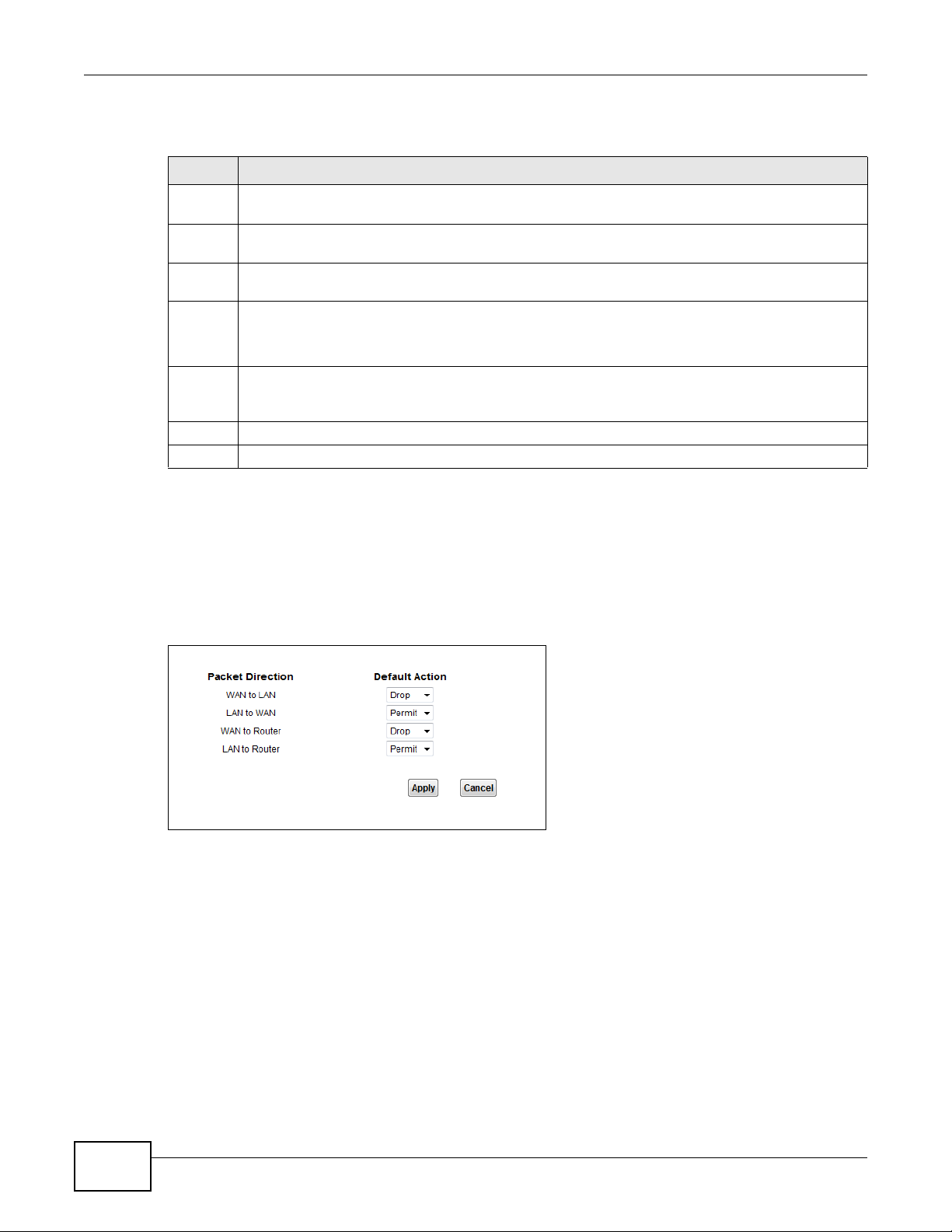
Chapter 10 Firewall
The following table describes the labels in this screen.
Table 22 Security > Firewall > General
LABEL DESCRIPTION
High This setting blocks all traffic to and from the Internet. Only local network traffic and LAN to WAN
Medium This is the recommended setting. It allows traffic to the Internet but blocks anyone from the
Low This setting allows traffic to the Internet and also allows someone from the Internet to access
Custom Use this setting to be able to create and edit individual firewall rules.
Off This setting is not recommended. It disables firewall protection for your network and could
Apply Click this to save your changes.
Cancel Click this to restore your previously saved settings.
service (Telnet, FTP, HTTP, HTTPS, DNS, POP3, SMTP) is permitted.
Internet from accessing any services on your local network.
services on your local network. This would be used with Port Forwarding, Default Server.
Firewall rules can be created in the Default Action screen (Section 10.3 on page 76) and Rules
screen (Section 10.4 on page 77).
potentially expose your network to significant security risks. This option should only be used for
troubleshooting or if you intend to use another firewall in conjunction with your router.
10.3 Default Action Screen
Use this screen to set the default action that the firewall takes on packets that do not match any of
the firewall rules. Click Security > Firewall > Default Action to display the following screen.
Figure 51 Security > Firewall > Default Action
76
LTE7410 User’s Guide
Page 77

Chapter 10 Firewall
The following table describes the labels in this screen.
Table 23 Security > Firewall > Default Action
LABEL DESCRIPTION
Packet Direction This is the direction of travel of packets (WAN to LAN , LAN to WAN, WAN to Router,
Default Action Use the drop-down list boxes to select the default action that the firewall is to take on
Apply Click this to save your changes.
Cancel Click this to restore your previously saved settings.
LAN to Router).
Firewall rules are grouped based on the direction of travel of packets to which they apply .
For example, LAN to Router means packets traveling from a computer/subnet on the
LAN to the LTE Device itself.
packets that are traveling in the selected direction and do not match any of the firewall
rules.
Select Drop to silently discard the packets without sending a TCP reset packet or an ICMP
destination-unreachable message to the send er.
Select Reject to deny the packets and send a TCP reset packet (for a TCP packet) or an
ICMP destination-unreachable message (for a UDP packet) to t he sender.
Select Permit to allow the passage of the packets.
10.4 Rules Screen
Click Security > Firewall > Rules to display the following screen. This screen displays a list of the
configured firewall rules. Note the order in which the rules are listed.
The ordering of your rules is very important as rules are applied in turn.
Figure 52 Security > Firewall > Rules
The following table describes the labels in this screen.
Table 24 Security > Firewall > Rules
LABEL DESCRIPTION
Firewall Rules Storage
Space in Use
Packet Direction U se the drop-down list box to select a direction of travel of packets for whic h you
Create a new rule
after rule number
This read-only bar shows how much of the LTE Device's memory for recording
firewall rules it is currently using. When you are using 80% or less of the storage
space, the bar is green. When the amount of space used is over 80%, the bar is red.
want to configure firewall rules.
Select an index number and click Add to add a new firewall rule after the selected
index number. For example, if you select “6”, your new rule becomes number 7 and
the previous rule 7 (if there is one) becomes rule 8.
LTE7410 User’s Guide
77
Page 78

Chapter 10 Firewall
10.4.1 Rules Add Screen
Use this screen to configure firewall rules. In the Rules screen, select an index number and click
Add or click a rule’s Edit icon to display this screen and refer to the following table for information
on the labels.
Figure 53 Security > Firewall > Rules > Add
78
The following table describes the labels in this screen.
Table 25 Security > Firewall > Rules > Add
LABEL DESCRIPTION
Edit Rule
Active Select this option to enable this firewall rule.
Action for Matched
Packets
Rate Limit Set a maximum number of packets per second, minute, or hour to limit the
Use the drop-down list box to select whether to discard (Drop), deny and send an
ICMP destination-unreachable message to the sender of (Reject) or allow the
passage of (Permit) packets that match this rule.
throughput of traffic that matches this rule.
LTE7410 User’s Guide
Page 79

Chapter 10 Firewall
Table 25 Security > Firewall > Rules > Add (continued)
LABEL DESCRIPTION
Maximum Burst
Number
Log This field determines if a log for packets that match the rule is created or not.
Rules/Source Address
Address Type Do you want your rule to apply to packets with a particular (single) IP, a range of IP
Start IP Address Enter the single IP address or the starting IP address in a range here.
End IP Address Enter the ending IP address in a range here.
Subnet Mask Enter the subnet mask here, if applicable.
Source Mac Address Specify a source MAC address of traffic to which to apply this firewall rule applies.
Destination Address
Address Type Do you want your rule to apply to packets with a particular (single) IP, a range of IP
Start IP Address Enter the single IP address or the starting IP address in a range here.
End IP Address Enter the ending IP address in a range here.
Subnet Mask Enter the subnet mask here, if applicable.
Service
Available Services Select a service from the Available Services box.
Edit Customized
Services
TCP Flag Specify any TCP flag bits the firewall rule is to check for.
Schedule Select the days and time during which to apply the rule. Select Everyday and All
OK Click this to save your changes.
Cancel Click this to exit this screen without saving.
Set the maximum number of packets that can be sent at the peak rate.
addresses (for instance, 192.168.1.10 to 192.169.1.50) , a subnet or any IP address?
Select an option from the drop-down list box that includes: Single Address, Range
Address, Subnet Address and Any
Please note that a blank source MAC address is equivalent to any.
addresses (for instance, 192.168.1.10 to 192.169.1.50) , a subnet or any IP address?
Select an option from the drop-down list box that includes: Single Address, Range
Address, Subnet Address and Any
Click the Edit Customized Service button to bring up the screen that you use to
configure a new custom service that is not in the predefined li st of services.
Day to always apply the rule.
Address.
Address.
10.4.2 Customized Services
Configure customized services and port numbers not predefined by the LTE Device. For a
comprehensive list of port numbers and services, visit the IANA (Internet Assigned Number
Authority) website. Click the Edit Customized Services button while editing a firewall rule to
configure a custom service port. This displays the following screen.
LTE7410 User’s Guide
79
Page 80

Chapter 10 Firewall
Figure 54 Security > Firewall > Rules: Add: Edit Customized Services
The following table describes the labels in this screen.
Table 26 Security > Firewall > Rules: Add: Edit Customized Services
LABEL DESCRIPTION
# This is the number of your customized port.
Name This is the name of your customized service.
Protocol This shows the IP protocol (TCP or UDP) that defines your customized service.
Port Type This is the port number or range that defines your customized service.
Start Port This is a single port number or the starting port number of a range that defines your
customized service.
End Port This is a single port number or the ending port number of a range that defines your customized
service.
Modify Click this to edit a customized service.
Add Click this to configure a customized service.
OK Click this to return to the Firewall Edit Rule screen.
10.4.3 Customized Service Add
Use this screen to add a customized rule or edit an existing rule. Click Add icon in the Customized
Services screen to display the following screen.
80
LTE7410 User’s Guide
Page 81

Chapter 10 Firewall
Figure 55 Security > Firewall > Rules: Add: Edit Customized Services: Add
The following table describes the labels in this screen.
Table 27 Security > Firewall > Rules: Edit: Edit Customized Services: Add/Edit
LABEL DESCRIPTION
Config
Service Name Type a unique name for your custom port.
Service Type Choose the IP port (TCP or UDP) that defi nes your cu stomized port from the drop down list
Port Configuration
Type Click Single to specify one port only or Port Range to specify a span of ports that define
Port Number Type a single port number or the range of port numbers that define your customized
Apply Click this to save your changes.
Back Click this to exit this screen without saving.
box.
your customized service.
service.
10.5 DoS Screen
Use this screen to enable DoS protection. Click Security > Firewall > Dos to display the following
screen.
Figure 56 Security > Firewall > Dos
LTE7410 User’s Guide
81
Page 82

Chapter 10 Firewall
The following table describes the labels in this screen.
Table 28 Security > Firewall > Dos
LABEL DESCRIPTION
Denial of Services Enable this to protect against DoS attacks. The LTE Device will drop sessions that s urpass
Apply Click this to save your changes.
Cancel Click this to restore your previously saved settings.
Advanced Click this to go to a screen to specify maximum thresholds at which the LTE Device will
maximum thresholds.
start dropping sessions.
10.5.1 The DoS Advanced Screen
For DoS attacks, the LTE Device uses thresholds to determine when to start dropping sessions that
do not become fully established (half-open sessions). These thresholds apply globally to all
sessions.
For TCP, half-open means that the session has not reached the established state-the TCP three-way
handshake has not yet been completed. Under normal circumstances, the application that initiates
a session sends a SYN (synchronize) packet to the receiving server . The receiv er sends back an ACK
(acknowledgment) packet and its own SYN, and then the initiator responds with an ACK
(acknowledgment). After this handshake, a connection is established.
Figure 57 Three-Way Handshake
For UDP, half-open means that the firewall has detected no return tr affic. An unusually high number
(or arrival rate) of half-open sessions could indicate a DOS attack.
10.5.1.1 Threshold Values
If everything is working properly , you probably do not need to change the threshold settings as the
default threshold values should work for most small offices. Tune these parameters when you
believe the L TE Device has been receiving DoS attacks that are not recorded in the logs or the logs
show that the L TE Device is classifying normal tr affic as DoS attacks. Factors influencing choices for
threshold values are:
1 The maximum number of opened sessions.
2 The minimum capacity of server backlog in your LAN network.
82
LTE7410 User’s Guide
Page 83

3 The CPU power of servers in your LAN network.
4 Network bandwidth.
5 Type of traffic for certain servers.
Reduce the threshold values if your network is slower than average for any of these factors
(especially if you have servers that are slow or handle many tasks and are often busy).
• If you often use P2P applications such as file sharing with eMule or eDonkey, it’s recommended
that you increase the threshold values since lots of sessions will be established during a small
period of time and the LTE Device may classify them as DoS attacks.
10.5.2 Configuring Firewall Thresholds
Click Security > Firewall > DoS > Advanced to display the following screen.
Figure 58 Security > Firewall > DoS > Advanced
Chapter 10 Firewall
The following table describes the labels in this screen.
Table 29 Security > Firewall > DoS > Advanced
LABEL DESCRIPTION
TCP SYN Flood Threshold
TCP SYN-Request
Count
UDP Packet Threshold
UDP Packet Count This is the rate of new UDP half-open sessions per second that causes the firewall to
ICMP Echo-Request Threshold
ICMP Echo-Request
Count
Others
LTE7410 User’s Guide
This is the rate of new TCP half-open sessions per second that causes the firewall to
start deleting half-open sessions. When the rate of new connection attempts rises
above this number, the LTE Device deletes half-open sessions as required to
accommodate new connection attempts.
start deleting half-open sessions. When the rate of new connection attempts rises
above this number, the LTE Device deletes half-open sessions as required to
accommodate new connection attempts.
This is the rate of new ICMP Echo-Request half-open sessions per second that causes
the firewall to start deleting half-open sessions. When the rate of new connection
attempts rises above this number, the LTE Device deletes half-open sessions as
required to accommodate new connection attempts.
83
Page 84

Chapter 10 Firewall
Table 29 Security > Firewall > DoS > Advanced (continued)
LABEL DESCRIPTION
ICMP Redirect Select Enable to monitor for and block ICMP redirect attacks.
An ICMP redirect attack is one where forged ICMP redirect messages can force the
client device to route packets for certain connections through an attacker’s host.
DoS Log(Log Level:
DEBUG)
OK Click this to save your changes.
Cancel Click this to exit this screen without saving.
Select Enable to log DoS attacks. See Section 15.3 on page 125 for information on
viewing logs.
10.6 Firewall Technical Reference
This section provides some technical background information about the topics covered in this
chapter.
10.6.1 Firewall Rules Overview
Your customized rules take precedence and override the LTE Device’s default settings. The LTE
Device checks the source IP address, destination IP address and IP protocol type of network traffic
against the firewall rules (in the order you list them). When the traffic matches a rule, the LTE
Device takes the action specified in the rule.
Firewall rules are grouped based on the direction of travel of packets to which they apply:
•LAN to Router •WAN to LAN
• LAN to WAN • WAN to Router
By default, the LTE Device’s stateful packet inspection allows packets traveling in the following
directions:
•LAN to Router
These rules specify which computers on the LAN can manage the LTE Device (remote
management).
Note: You can also configure the remote management settings to allow only a specific
computer to manage the LTE Device.
•LAN to WAN
These rules specify which computers on the LAN can access which computers or services on the
WAN.
84
By default, the LTE Device’s stateful packet inspection drops packets traveling in the following
directions:
•WAN to LAN
These rules specify which computers on the WAN can access which computers or services on the
LAN.
LTE7410 User’s Guide
Page 85

Chapter 10 Firewall
Note: You also need to configure NAT port forwarding (or full featured NAT address
mapping rules) to allow compu ters on the WAN to access devices on the LAN.
•WAN to Router
By default the LTE Device stops computers on the W AN from managing the LTE Device. You could
configure one of these rules to allow a WAN computer to manage the LTE Device.
Note: You also need to configure the remote management settings to allow a WAN
computer to manage the LTE Device.
You may define additional rules and se ts or modify existing ones but please exercise extreme
caution in doing so.
For example, you may create rules to:
• Block certain types of traffic, such as IRC (Internet Relay Chat), from the LAN to the Internet.
• Allow certain types of traffic, such as Lotus Notes database synchronization, from specific hosts
on the Internet to specific hosts on the LAN.
• Allow everyone except your competitors to access a web server.
• Restrict use of certain protocols, such as Telnet, to authorized users on the LAN.
These custom rules work by comparing the source IP address, destination IP address and IP
protocol type of network traffic to rules set by the administrator. Your customized rules take
precedence and override the LTE Device’s default rules.
10.6.2 Guidelines For Enhancing Security With Your Firewall
1 Change the default password via web configurator.
2 Think about access control before you connect to the network in any way.
3 Limit who can access your router.
4 Don't enable any local service (such as telnet or FTP) that you don't use. Any enabled service could
present a potential security risk. A determined hacker might be able to find creative ways to misuse
the enabled services to access the firewall or the network.
5 For local services that are enabled, protect against misuse. Protect by configuring the services to
communicate only with specific peers, and protect by configuring rules to block packets for the
services at specific interfaces.
6 Protect against IP spoofing by making sure the firewall is active.
7 Keep the firewall in a secured (locked) room.
10.6.3 Security Considerations
Note: Incorrectly configuring the firewall may block valid access or introduce security
risks to the LTE Device and your protected network. Use caution when creating or
deleting firewall rules and test your rules after you configure them.
LTE7410 User’s Guide
85
Page 86

Chapter 10 Firewall
Consider these security ramifications before creating a rule:
1 Does this rule stop LAN users from accessing critical resources on the Internet? For example, if IRC
is blocked, are there users that require this service?
2 Is it possible to modify the rule to be more specific? For example, if IRC is blocked for all users, will
a rule that blocks just certain users be more effective?
3 Does a rule that allows Internet users access to resources on the LAN create a security
vulnerability? For example, if FTP ports (TCP 20, 21) are allowed from the Internet to the LAN,
Internet users may be able to connect to computers with running FTP servers.
4 Does this rule conflict with any existing rules?
Once these questions have been answered, adding rules is simply a matter of entering the
information into the correct fields in the web configurator screens.
86
LTE7410 User’s Guide
Page 87

CHAPTER 11
11.1 Overview
The LTE Device can use certificates (also called digital IDs) to authenticate users. Certificates are
based on public-private key pairs. A certificate contains the certificate owner’s identity and public
key. Certificates provide a way to exchange public keys for use in authentication.
11.1.1 What You Can Do in this Chapter
•Use the Local Certificates screen to view and import the LTE Device’s CA-signed certificates
(Section 11.2 on page 89).
•Use the Trusted CA screen to save the certificates of trusted CAs to the L TE Device. Y ou can also
export the certificates to a computer (Section 11.3 on page 91).
Certificates
11.1.2 What You Need to Know
The following terms and concepts may help as you read this chapter.
Certification Authorities
A Certification Authority (CA) issues certificates and guarantees the identity of each certificate
owner. There are commercial certification authorities like CyberTrust or VeriSign and government
certification authorities.
Public and Private Keys
When using public-key cryptology for authentication, each host has two keys. One key is public and
can be made openly available; the other key is private and must be kept se cure. Public-key
encryption in general works as follows.
1 Tim wants to send a private message to Jenny. Tim generates a public-private key pair. What is
encrypted with one key can only be decrypted using the other.
2 Tim keeps the private key and makes the public key openly available.
3 Tim uses his private key to encrypt the message and sends it to Jenny.
4 Jenny receives the message and uses Tim’s public key to decrypt it.
5 Additionally , Jenn y uses her own priv ate key to encrypt a message and Tim uses Jenny’s public key
to decrypt the message.
LTE7410 User’s Guide 87
Page 88

Chapter 11 Certificates
The L TE Device uses certificates based on public-key cryptology to authenticate users attempting to
establish a connection. The method used to secure the data that you send through an established
connection depends on the type of connection. For example, a VPN tunnel might use the triple DES
encryption algorithm.
The certification authority uses its private key to sign certificates. Anyone can then use the
certification authority’s public key to verify the certificates.
Certification Path
A certification path is the hierarchy of certification authority certificates that validate a certificate.
The L TE Device does not trust a certificate if any certificate on its path has expired or been revoked.
Certificate Directory Servers
Certification authorities maintain directory servers with databases of valid and revoked certificates.
A directory of certificates that have been revoked before the scheduled expiration is called a CRL
(Certificate Revocation List). The LTE Device can check a peer’s certificate against a directory
server’s list of revoked certificates. The framework of servers, software, procedures and policies
that handles keys is called PKI (public-key infrastructure).
Advantages of Certificates
Certificates offer the following benefits.
• The L TE Device only has to store the certificates of the certification authorities that you decide to
trust, no matter how many devices you need to authenticate.
• Key distribution is simple and very secure since you can freely distribute public keys and you
never need to transmit private keys.
Certificate File Format
The certification authority certificate that you want to import has to be in PEM (Base-64) encoded
X.509 file format. This Privacy Enhanced Mail format uses 64 ASCII characters to convert a binary
X.509 certificate into a printable form.
11.1.3 Verifying a Certificate
Before you import a trusted CA or trusted remote host certificate into the LTE Device, you should
verify that you have the actual certificate. This is especially true of trusted CA certificates since the
LTE Device also trusts any valid certificate signed by any of the imported trusted CA certificates.
You can use a certificate’s fingerprint to verify it. A certificate’s fingerprint is a message digest
calculated using the MD5 or SHA1 algorithms. The following procedure describes how to check a
certificate’s fingerprint to verify that you have the actual certificate.
1 Browse to where you have the certificate saved on your computer.
88
LTE7410 User’s Guide
Page 89

Chapter 11 Certificates
2 Make sure that the certificate has a “.cer” or “.crt” file name extension.
Figure 59 Certificates on Your Computer
3 Double-click the certificate’s icon to open the Certificate window. Click the Details tab and scroll
down to the Thumbprint Algorithm and Thumbprint fields.
Figure 60 Certificate Details
4 Use a secure method to verify that the certificate owner has the same information in the
Thumbprint Algorithm and Thumbprint fields. The secure method may very based on your
situation. Possible examples would be over the telephone or through an HTTPS connection.
11.2 Local Certificates
Use this screen to view the LTE Device’ s summary list of certificates and certification requests. You
can import the following certificates to your LTE Device:
• Web Server - This certificate secures HTTP connections.
• SSH- This certificate secures remote connections.
LTE7410 User’s Guide
89
Page 90

Chapter 11 Certificates
Click Security > Certificates to open the Local Certificates screen.
Figure 61 Security > Certificates > Local Certificates
The following table describes the labels in this screen.
Table 30 Security > Certificates > Local Certificates
LABEL DESCRIPTION
WebServer Click Browse... to find the certificate file you wa nt to upload .
Current File This field displays the name used to identify this certificate. It is recommended that you
give each certificate a unique name.
Subject This field displays identifying information about the certificate’s owner, such as CN
(Common Name), OU (Organizational Unit or department), O (Organization or company)
and C (Country). It is recommended that each certificate have unique subject
information.
Issuer This field displays identifying information about the certificate’s issuing certification
authority, such as a common name, organizational unit or department, organization or
company and country.
Valid From This field displays the date that the certificate becomes applicable. The text displays in
red and includes a Not Yet Valid! message if the certificate has not yet become
applicable.
Valid To This field displays the date that the certificate expires. The text displays in red and
Cert Click this button and then Save in the File Download screen. The Save As screen
SSH Type in the location of the SSH certificate file you want to upload in this field or click
Current File This field displays the name used to identify this certificate. It is recommended that you
Key Type This field applies to the SSH/SCP/SFTP certificate.
Replace Click this to replace the certificates and save your changes back to the LTE Device.
Reset Click this to clear your settings.
includes an Expiring! or Expired! message if the certificate is about to expire or has
already expired.
opens, browse to the location that you want to use and click Save.
Browse to find it.
give each certificate a unique name.
This shows the file format of the current certificate.
90
LTE7410 User’s Guide
Page 91

11.3 Trusted CA
Use this screen to view a summary list of certificates of the certification authorities that you have
set the LTE Device to accept as trusted. The LTE Device accepts any valid certificate signed by a
certification authority on this list as being trustworthy; thus you do not need to import any
certificate that is signed by one of these certification authorities.
Click Security > Certificates > Trusted CA to open the Trusted CA screen.
Figure 62 Security > Certificates > Trusted CA
The following table describes the labels in this screen.
Table 31 Security > Certificates > Trusted CA
LABEL DESCRIPTION
Import Certificate Click this button to open a screen where you can save the certificate of a certification
authority that you trust to the LTE Device.
Name This fi eld displays the name used to identify this certificate.
Subject This field displays information that identifies the owner of the certificate, such as Common
Name (CN), OU (Organizational Unit or department), Organization (O), State (ST) and
Country (C). It is recommended that each certificate have unique subject information.
Type This field displays gen eral information about the certificate. ca means that a Certification
Authority signed the certificate.
Action Click the View icon to open a screen with an in-depth list of information about the
certificate (or certification request).
Chapter 11 Certificates
Click the Delete icon to delete the certificate (or certification request). You cannot delete
a certificate that one or more features is configured to use.
11.4 Trusted CA Import
Click Import Certificate in the Trusted CA screen to open the Import Certificate screen. You
can save a trusted certification authority’s certificate to the LTE Device.
LTE7410 User’s Guide
91
Page 92

Chapter 11 Certificates
Note: You must remove any spaces from the certificate’s filename before you can import
the certificate.
Figure 63 Trusted CA > Import
The following table describes the labels in this screen.
Table 32 Security > Certificates > Trusted CA > Import
LABEL DESCRIPTION
Certificate File
Path
Browse Click Browse to find the certificate file you want to upload.
Apply Click this to save the certificate on the LTE Device.
Cancel Click this to exit this screen without saving.
Type in the location of the file you want to upload in this field or click Browse to find it.
11.5 View Certificate
Use this screen to view in-depth information about the certification authority’s certificate, change
the certificate’s name and set whether or not you want the LTE Device to check a certification
authority’s list of revoked certificates before trusting a certificate issued by the certification
authority.
92
LTE7410 User’s Guide
Page 93
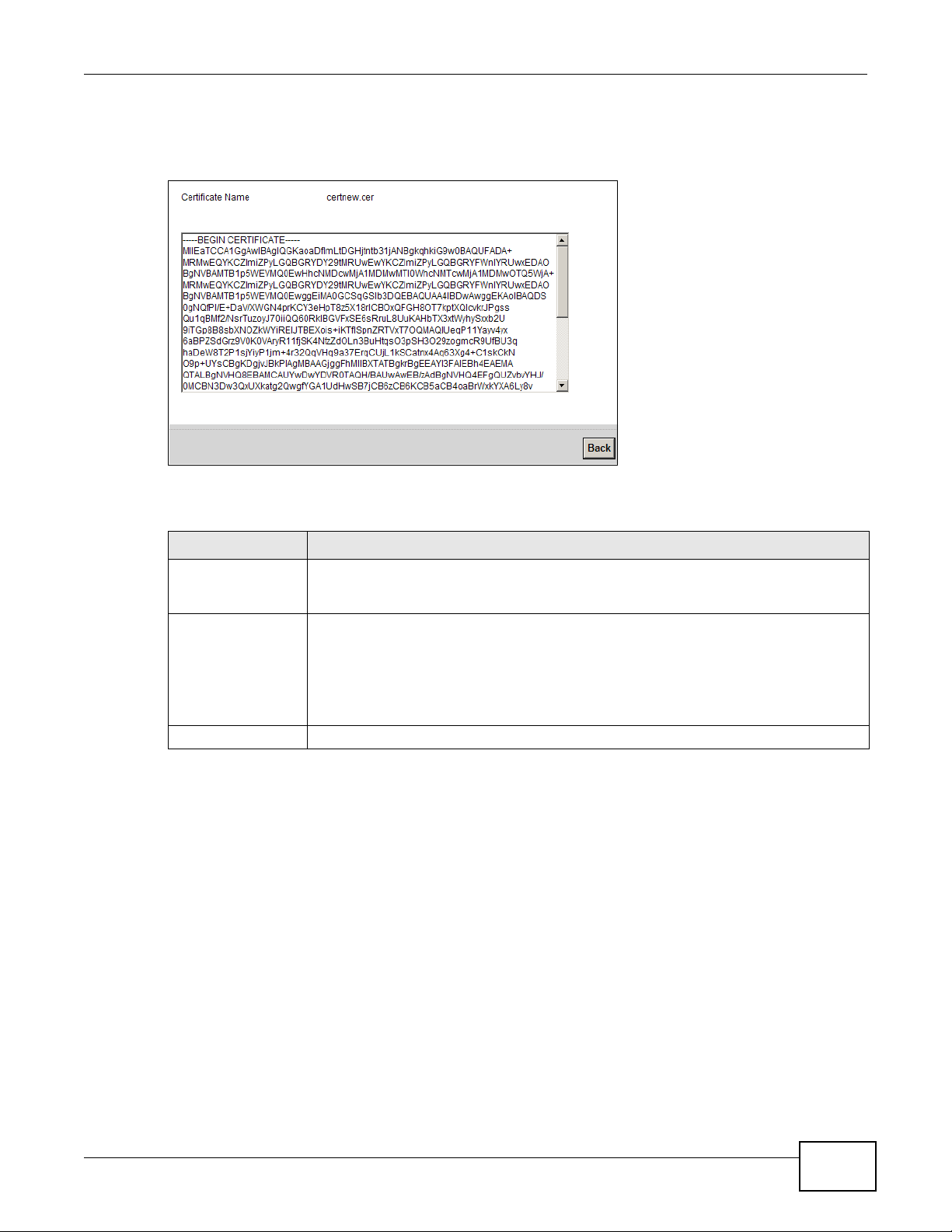
Chapter 11 Certificates
Click Security > Certificates > Trusted CA to open the Trusted CA screen. Click the View icon
to open the View Certificate screen.
Figure 64 Trusted CA: View
The following table describes the labels in this screen.
Table 33 Trusted CA: View
LABEL DESCRIPTION
Certificate Name This field displays the identifying name of this certificate. If you want to change the
Certificate Detail This read-only text box displays the certificate or certification request in Privacy
Back Click this to return to the previous screen.
name, type up to 31 characters to identify this key certificate. You may use any
character (not including spaces).
Enhanced Mail (PEM) format. PEM uses 64 ASCII characters to convert the binary
certificate into a printable form.
You can copy and paste the certificate into an e-mail to send to friends or colleagues or
you can copy and paste the certificate into a text editor and save the file on a
management computer for later distribution (via floppy disk for example).
LTE7410 User’s Guide
93
Page 94

Chapter 11 Certificates
94
LTE7410 User’s Guide
Page 95

12.1 Overview
L2TP VPN tunnels network traffic between the LTE Device and a peer device or server over the
Internet.
12.2 The Setup Screen
Use this screen to view and manage L2TP VPN tunnels. Click Security > L2TP VPN to open the
following screen.
Figure 65 Security > L2TP VPN
CHAPTER 12
L2TP VPN
The following table describes the labels in this screen.
Table 34 Security > L2TP VPN
LABEL DESCRIPTION
# This shows the index number of an L2TP tunnel.
Active This shows whether the L2TP VPN is on or not.
Default Route This shows the default route is on or not.
Tunnel Name This shows the name of this tunnel.
L2TP Server IP This shows the IP address of the remote gateway with which the LTE Device establishes
User Name The remote user must log into the LTE Device to use the L2TP VPN tunnel. This shows a
Auth Select the protocol (EAP, MSCHAPv1 or MSCHAPv2) the LTE Device uses for user
Modify Click the Edit icon to go to the screen where you can edit the L2TP VPN tunnel.
LTE7410 User’s Guide 95
the L2TP tunnel.
user or user group that can use the L2TP VPN tunnel.
authentication.
Page 96

Chapter 12 L2TP VPN
12.3 The Edit L2TP Tunnel Screen
Use this screen to modify a L2TP VPN tunnel. Click Edit icon in Security > L2TP VPN > Modify to
open the following screen.
Click Security > L2TP VPN > Modify to open the L2TP Tunnel Edit screen.
Figure 66 Security > L2TP VPN > Modify
The following table describes the labels in this screen.
Table 35 Security > L2TP VPN > Modify
LABEL DESCRIPTION
Active Click this to activate the L2TP VPN.
Default Route Click this to activate the default route.
L2TP Tunnel
Name
Secure Gateway
Address
Username The remote user must log into the LTE Device to use the L2TP VPN tunnel. This shows a
Password Enter the password for the user.
Auth Select the protocol (EAP, MSCHAPv1 or MSCHAPv2) the LTE Device uses for user
OK Click this button to save your settings back to the LTE Device.
Cancel Click this button to return to the previous screen without saving any changes.
This shows the IP address that the LTE Device assigned for the remote user's computer to
use within the L2TP VPN tunnel.
If you configure this field to 0.0.0.0 or leave it blank, the LTE Device will use the address
in the Secure Gateway Address field (refer to the Secure Gateway Address field
description).
user or user group that can use the L2TP VPN tunnel.
authentication.
96
LTE7410 User’s Guide
Page 97

13.1 Overview
GRE (Generic Routing Encapsulation) tunnels encapsulate a wide variety of network layer protocol
packet types inside IP tunnels. A GRE tunnel serves as a virtual point-to-point link between the LTE
Device and another router over an IPv4 network.
13.2 The Setup Screen
Use this screen to view and manage GRE VPN tunnels. Click Security > GRE VPN to open the
following screen.
Figure 67 Security > GRE VPN
CHAPTER 13
GRE VPN
The following table describes the labels in this screen.
Table 36 Security > L2TP VPN
LABEL DESCRIPTION
# This shows the index number of a GRE tunnel.
Active The check box is selected if the GRE VPN tunnel is enabled.
Tunnel Name This shows the name of this tunnel.
GRE Layer This shows whether the GRE VPN tunnels Layer 2 or Layer 3 protocol traffic.
Server IP Address This is the IP address or domain name of the remote gateway to which the LTE Device’s
Local IP Address This is the local hosts’ IP addresses for which the LTE Device tunnels traffic sent to the
Remote IP
Address
Modify Click the Edit icon to go to the screen where you can edit the GRE VPN tunnel.
WAN interface tunnels traffic.
remote gateway.
This is the remote hosts’ IP addresses behind the remote gateway to which the L TE Device
tunnels traffic.
LTE7410 User’s Guide 97
Page 98

Chapter 13 GRE VPN
13.3 The Edit GRE Tunnel Screen
Use this screen to modify a GRE VPN tunnel. Click Edit icon in Security > GRE VPN > Modify to
open the following screen.
Figure 68 Security > GRE VPN > Modify
The following table describes the labels in this screen.
Table 37 Security > GRE VPN > Modify
LABEL DESCRIPTION
Active Click this to activate the GRE VPN.
Tunnel Name Enter a descriptive name for the GRE tunnel.
GRE Layer Select which OSI layer (Layer2 or Layer3) protocol the GRE tunnels over a network. Use
Server IP Address Enter the IP address or domain name of the remote gateway to which the LTE Device's
OK Click this button to save your settings back to the LTE Device.
Back Click this button to return to the previous screen without saving any changes.
layer 2 when 1 local LAN PC and 1 LAN PC behind the remote gateway IPs are in the same
subnet domain. Use layer 3 when the LAN PC IPs are in diffe rent subnet domains.
WAN interface tunnels traffic.
98
LTE7410 User’s Guide
Page 99

CHAPTER 14
14.1 Overview
Use this chapter to:
• Connect an analog phone to the LTE Device.
• Make phone calls over the Internet, as well as the regular phone network.
• Configure settings such as speed dial.
• Configure network settings to optimize the voice quality of your phone calls.
14.1.1 What You Can Do in this Chapter
These screens allow you to configure your LTE Device to make phone calls over the Internet and
your regular phone line, and to set up the phones you connect to the LTE Device.
VoIP
•Use the SIP Account screens to set up information about your SIP account, control which SIP
accounts the phones connected to the LTE Device use and configure audio settings such as
volume levels for the phones connected to the ZyXEL Device (Section 14.2 on page 101).
•Use the SIP Service Provider screens to configure the SIP server information, and the numbers
for certain phone functions (Section 14.3 on page 104).
•Use the Phone screen to change settings that depend on the country you are in ( Section 14.4 on
page 112).
•Use the Call Rule screen to set up shortcuts for dialing frequently-used (VoIP) phone numbers
(Section 14.5 on page 112).
You don’t necessarily need to use all these screens to set up your account. In fact, if your service
provider did not supply information on a particular field in a screen, it is usually best to leave it at
its default setting.
14.1.2 What You Need to Know
The following terms and concepts may help as you read this chapter.
VoIP
VoIP stands for Voice over IP. IP is the Internet Protocol, which is the message-carrying standard
the Internet runs on. So, Voice over IP is the sending of voice signals (speech) over the Internet (or
another network that uses the Internet Protocol).
LTE7410 User’s Guide 99
Page 100

Chapter 14 VoIP
SIP
SIP stands for Session Initiation Protocol. SIP is a signalling standard that lets one network device
(like a computer or the LTE Device) send messages to another. In VoIP, these messages are about
phone calls over the network. For example, when you dial a number on y our LTE Device, it sends a
SIP message over the network asking the other device (the number you dialed) to take part in the
call.
SIP Accounts
A SIP account is a type of VoIP account. It is an arrangement with a service provider that lets you
make phone calls over the Internet. When you set the LTE Device to use your SIP account to make
calls, the L TE Device is able to send all the information about the phone call to your service provider
on the Internet.
Strictly speaking, you don’t need a SIP account. It is possible for one SIP device (like the LTE
Device) to call another without involving a SIP service provider. However, the networking difficulties
involved in doing this make it tremendously impractical under normal circumstances. Your SIP
account provider removes these difficulties by taking care of the call routing and setup - figuring
out how to get your call to the right place in a way that you and the othe r person can talk to one
another.
Voice Activity Detection/Silence Suppression
Voice Activity Detection (VAD) detects whether or not speech is present. This lets the LTE Device
reduce the bandwidth that a call uses by not transmitting “silent packets” when you are not
speaking.
Comfort Noise Generation
When using VAD, the LTE Device generates comfort noise when the other party is not speaking. The
comfort noise lets you know that the line is still connected as total silence could easily be mistaken
for a lost connection.
Echo Cancellation
G.168 is an ITU-T standard for eliminating the echo caused by the sound of your voice
reverberating in the telephone receiver while you talk.
Use this screen to maintain basic information about each SIP account. You can also enable and
disable each SIP account, configure the volume, echo cancellation and VAD (Voice Activity
Detection) settings for each individual phone port on the LTE Device.
How to Find Out More
See page 113 for advanced technical information on SIP.
14.1.3 Before You Begin
• Before you can use these screens, you need to have a VoIP account already set up. If you don’t
have one yet, you can sign up with a VoIP service provider over the Internet.
100
LTE7410 User’s Guide
 Loading...