

Page 1

See the User's Guide at www.zyxel.com for more
information, including customer support and
safety warnings.
EU Importer
Zyxel Communications A/S
Gladsaxevej 378, 2. th. 2860 Søborg, Denmark
http://www.zyxel.dk
US Importer
Zyxel Communications, Inc
1130 North Miller Street Anaheim, CA 92806-2001
http://www.us.zyxel.com
Copyright © 2018 Zyxel Communications Corp.
All Rights Reserved.
LTE7240-M403
4G LTE Outdoor Router
Quick Start Guide
ENGLISH | DEUTSCH | ESPAÑOL
FRANÇAIS | ITALIANO | DANSK
NEDERLANDS | NORSK | SUOMI
SVENSKA | ČEŠTINA | MAGYAR
POLSKI | ROMÂNĂ | SLOVENČINA
SLOVENŠČINA | БЪЛГАРСКИ | РУССКИЙ
Page 2

Package ContentsSupport Information
UK
+ 44 (0) 118 912 1700
support@zyxel.co.uk
Germany
+ 49 (0) 2405 - 69 09 69
support@zyxel.de
Spain
+ 34 911 792 100
soporte@zyxel.es
France
+ 33 (0) 4 72 52 97 97
support@zyxel.fr
Italy
+ 39 011 2308000
support@zyxel.it
Denmark
+ 45 39 55 07 85
support@zyxel.dk
Netherlands
+ 31 (0) 88-00029112
support@zyxel.nl
Norway
+ 47 22 80 61 80
teknisk@zyxel.no
Finland
+ 358 9 4780 8411
teknisk@zyxel.fi
Sweden
+ 46 8 557 760 60
support@zyxel.se
1 2
Czech
+ 420 241 774 665
support@cz.zyxel.com
Hungary
+ 36 1 848 0690
support@zyxel.hu
Poland
+ 48 (22) 333 8250
support@pl.zyxel.com
Romania
info@ro.zyxel.com
Slovakia
+ 421 220 861 847
soporte@sk.zyxel.com
Slovenia
+49 (0) 2405 6909 0
support@zyxel.eu
Bulgaria
support@zyxel.bg
Russia
+7 499 705 6107
support@zyxel.ru
PoE Injector
Mounting Kit
Ethernet Cable
Quick Start Guide
x2
9.35~9.40
A x 2
B x 1
Unit: mm
Power CordsLTE7240-M403
DoC
Declaration of Conformity
Safety Warning
Warranty Card
32~38
6.5~7.5
31~33
2.35~2.65
9.4~10
6.5~7
3.84~3.97
2.45~2.75
4~4.15
Page 3

1
Hardware Installation
1
1-a
1-a
2
* Insert a Micro-SIM card into the
slot with the chip facing down
and the beveled corner in the
top left corner.
Micro SIM
1-b
EN
1
Remove the bottom cover as shown.
Check that there is no Ethernet cable connected to
2
provide power using PoE. Insert your SIM card (Micro-SIM
card) to the SIM card slot for LTE network access.
Warning: If you are using a Nano-SIM card, insert it
correctly and securely into a SIM card adapter to avoid
possible damage to your device.
DE
1
Entfernen Sie die untere Abdeckung wie abgebildet.
Vergewissern Sie sich, dass kein Ethernet-Kabel für die
2
Stromversorgung über PoE angeschlossen ist. Setzen Sie
Ihre SIM-Karte (Micro-SIM-Karte) für den Zugriff auf das
LTE Netzwerk in den SIM-Karteneinschub ein.
Warnung: Wenn Sie eine Nano-SIM Karte verwenden,
legen Sie sie korrekt und fest in den SIM Kartenadapter
ein, um eine mögliche Beschädigung Ihres Geräts zu
verhindern.
ES
1
Retire la cubierta inferior como se muestra.
Verifique que no haya un cable Ethernet conectado con
2
alimentación mediante PoE. Inserte su tarjeta SIM (tarjeta
Micro-SIM) en la ranura para tarjeta SIM para el acceso a
la red LTE.
Aviso: Si utiliza una tarjeta Nano-SIM, insértela
correctamente en un adaptador de tarjetas SIM para
evitar posibles daños en su dispositivo.
ENGLISH
EN
| DEUTSCH
DE
| ESPAÑOL
ES
3 4
Page 4

1
Hardware Installation
EN
3-5
Put the Ethernet cable through the bottom cover hole and
seal the hole with the rubber plug. Connect the Ethernet
cable to the LTE7240-M403. Put the bottom cover back.
6
Connect the other end of the Ethernet cable to the
provided PoE injector's POE port.
7
Connect the LAN port of the PoE injector to a computer
with an Ethernet cable for initial configuration.
8
Connect the power cord to the PoE injector.
9
Connect the power plug on the power cord to a power outlet.
4
DE
3-5
Stecken Sie das Ethernet-Kabel durch die untere
Abdeckung und verschließen Sie die Öffnung mit dem
3
5
Gummistopfen. Schließen Sie das Ethernet-Kabel an den
LTE7240-M403 an. Legen Sie die untere Abdeckung zurück.
Schließen Sie das andere Ende des Ethernet-Kabels an
6
den POE Anschluss des beiliegenden PoE Injektors an.
Verbinden Sie den LAN Anschluss des PoE Injektors für die
7
erstmalige Einrichtung über ein Ethernet-Kabel mit einem
Computer.
8
POE LAN
6 7
PoE injector
(front)
LANPoE
Schließen Sie das Netzkabel an den PoE Injektor an.
9
Schließen Sie den Netzstecker des Netzkabels an eine
Steckdose an.
ES
3-5
Pase el cable Ethernet a través del orificio de la tapa inferior
y selle el orificio con el tapón de caucho. Conecte el cable
PoE injector
(back)
Power plug
9
8
Ethernet al LTE7240-M403. Vuelva a colocar la cubierta inferior.
6
Conecte el otro extremo del cable Ethernet al puerto POE
del inyector PoE.
7
Conecte el puerto LAN del inyector PoE a un ordenador
con cable Ethernet para la configuración inicial.
8
Conecte el cable de corriente al inyector PoE.
9
Conecte el enchufe del cable de alimentación en una
toma de corriente.
5 6
ENGLISH
EN
| DEUTSCH
DE
| ESPAÑOL
ES
Page 5

2
Wall Mounting
Option A
Using the Rear Mounting Bracket
1 2
2-a
62mm
Note:
See Package Contents for
screw A.
Insert the masonry plugs all
the way into the wall. Do not
insert the screws all the way
in - leave a small gap of 5.8
mm.
Screw A
Screw A
2-b
EN
Note: Install the LTE7240-M403 vertically with connector
hole facing down. Point the LTE7240-M403's front panel
towards the nearest base station.
1
Drill two holes on the wall at the distance of 62 mm. Insert
the masonry plugs and screws as shown.
2
Place the LTE7240-M403 so the wall mount holes line up
with the screws (2-a). Slide the LTE7240-M403 down gently
to fix it into place (2-b).
DE
Hinweis: Montieren Sie den LTE7240-M403 senkrecht mit der
Anschlussöffnung nach unten. Richten Sie die Vorderseite
des LTE7240-M403 auf die nächste Basisstation.
1
Bohren Sie im Abstand von 62 mm zwei Löcher in die Wand.
Setzen Sie die Dübel und Schrauben wie abgebildet ein.
2
Stellen Sie den LTE7240-M403 so auf, dass die Bohrungen
für die Wandmontage mit den Schrauben (2-a)
übereinstimmen. Schieben Sie den LTE7240-M403
vorsichtig nach unten, um ihn zu fixieren (2-b).
ES
Nota: Instale el LTE7240-M403 verticalmente con el orificio
del conector mirando hacia abajo. Apunte el panel frontal
del LTE7240-M403 hacia la estación base más cercana.
1
Taladre dos agujeros en la pared a una distancia de
62mm. Inserte los tacos y tornillos como se muestra.
2
Coloque el LTE7240-M403 de forma que los orificios del
soporte queden alineados con los tornillos (2-a). Deslice
suavemente el LTE7240-M403 hacia abajo para que
quede bien encajado (2-b).
ENGLISH
EN
| DEUTSCH
DE
| ESPAÑOL
ES
7 8
Page 6

2
Wall Mounting
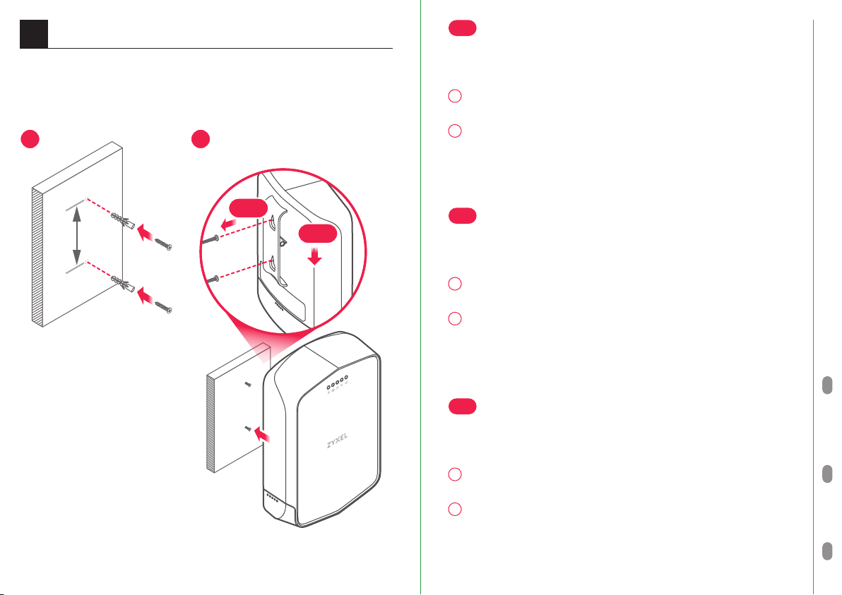
Option B
Using Mounting Kit
32mm
21
EN
1
Drill two holes on the wall at the distance of 32 mm.
Install the masonry plugs and screws as shown to secure
2
the bracket to the wall. Make sure the screws are snugly
and securely fastened to the wall.
3
Place the LTE7240-M403 so the wall mount holes on the
rear mounting bracket line up with hooks on the bracket
(3-a). Slide the LTE7240-M403 down gently to fix the
LTE7240-M403 into place (3-b).
4
Install the screw as shown to secure the LTE7240-M403 to
the bracket.
DE
Bohren Sie zwei Löcher im Abstand von 32 mm in die Wand.
Screw A
Screw A
3
4
1
2
Montieren Sie die Dübel und Schrauben wie abgebildet,
um die Halterung an der Wand zu befestigen. Stellen Sie
sicher, dass die Schrauben fest in der Wand befestigt sind.
Stellen Sie den LTE7240-M403 so auf, dass die Bohrungen
3
für die Wandmontage an der hinteren Halterung mit den
Haken an der Halterung (3-a) übereinstimmen. Schieben
Sie den LTE7240-M403 vorsichtig nach unten, um den
LTE7240-M403 zu fixieren (3-b).
4
Montieren Sie die Schraube wie abgebildet, um den
LTE7240-M403 an der Halterung zu befestigen.
ES
1
Perfore dos agujeros en la pared a una distancia de 32 mm.
2
3-a
3-b
Screw B
Note: See Package Contents
9 10
for screw A and B.
Instale los tacos y tornillos como se muestra para asegurar
el soporte a la pared. Asegúrese de que los tornillos estén
perfectamente apretados y seguros en la pared.
Coloque el LTE7240-M403 de manera que los orificios de
3
montaje en pared del soporte de montaje trasero queden
alineados con los ganchos del soporte (3-a). Deslice
suavemente el LTE7240-M403 hacia abajo para que el
LTE7240-M403 quede bien encajado (3-b).
Instale el tornillo como se muestra para asegurar el
4
LTE7240-M403 al soporte.
ENGLISH
EN
| DEUTSCH
DE
| ESPAÑOL
ES
Page 7

3
Internet Setup
http://192.168.1.1
User Name : admin
Password : 1234
(default)
LTE7240-M403
User Name
Password 1234
admin
Login
EN
Open a web browser and go to http://192.168.1.1. Enter the default
User Name (admin) and Password (1234), then click Login.
DE
Öffnen Sie einen Webbrowser und gehen Sie zu http://192.168.1.1.
Geben Sie den Standard Benutzernamen (admin) und Passwort
(1234) ein, und klicken Sie dann auf die Schaltfläche Anmelden.
ES
Abra un explorador web y vaya a http://192.168.1.1. Escriba el User
Name (admin) predeterminado y Password (1234) predetermina-
dos y haga clic en Login.
ENGLISH
EN
| DEUTSCH
DE
| ESPAÑOL
ES
Turning On/Off WiFi (Optional)
EN
LTE7240-M403 WiFi is disabled by default. To disable or
enable it again, press the WiFi button for five seconds.
DE
LTE7240-M403 WiFi ist standardmäßig deaktiviert. Um es zu
WiFi ON
deaktivieren oder wieder zu aktivieren, drücken Sie fünf
Sekunden lang auf die WiFi Taste.
ES
El WiFi del LTE7240-M403 está deshabilitado por defecto.
Para deshabilitarlo o habilitarlo, presione el botón WiFi
Press for 5 seconds to turn on/off WiFi
WiFi
11 12
Green
On - 2.4 GHz WiFi ready
durante cinco segundos.
Page 8

1
Hardware Installation
1
1-a
1-a
2
1-b
FR
1
Retirez le couvercle inférieur comme indiqué.
Vérifiez qu'aucun câble Ethernet n'est connecté pour
2
fournir l'énergie en utilisant PoE. Insérez votre carte SIM
(carte Micro-SIM) dans le logement pour carte SIM pour
accéder au réseau LTE.
Avertissement: Si vous utilisez une carte Nano-SIM,
insérez-la correctement dans un adaptateur pour carte
SIM pour éviter d'endommager votre appareil.
IT
1
Rimuovere il coperchio inferiore come mostrato.
Verificare che non sia collegato alcun cavo Ethernet per
2
l'alimentazione tramite PoE. Inserire la scheda SIM
(scheda Micro-SIM) nello slot della scheda SIM per
l'accesso alla rete LTE.
Attenzione: Se si utilizza una scheda nano-SIM, inserirla
correttamente e saldamente nell'adattatore della scheda
SIM per evitare possibili danni al dispositivo.
FRANÇAIS
* Insert a Micro-SIM card into the
slot with the chip facing down
and the beveled corner in the
top left corner.
DK
1
Fjern bunddækslet som vist.
Kontroller, at der ikke er tilsluttet et Ethernet-kabel som
2
strømforsyning, når der bruges PoE. Indsæt dit SIM-kort
(micro-SIM-kort) i SIM-kortslottet for adgang til
Micro SIM
LTE-netværk.
Advarsel: Hvis du bruger et Nano-SIM-kort, indsæt det
korrekt i en SIM-kortadapter for at undgå eventuelle
skader på din enhed.
13 14
FR
| ITALIANO
IT
| DANSK
DK
Page 9

1
Hardware Installation
FR
3-5
Passez le câble Ethernet par le trou du couvercle inférieur
et obturez le trou avec le bouchon en caoutchouc.
Connectez le câble Ethernet au LTE7240-M403. Remettez
le couvercle inférieur en place.
6
Connectez l'autre extrémité du câble Ethernet au port
POE de l'injecteur PoE fourni.
7
Connectez le port LAN de l'injecteur PoE à un ordinateur
avec un câble Ethernet pour la configuration initiale.
8
Connectez le cordon d'alimentation à l'injecteur PoE.
9
Branchez la fiche d'alimentation du cordon
4
d'alimentation à une prise de courant.
IT
3-5
3
5
POE LAN
6 7
PoE injector
(front)
(back)
LANPoE
Power plugPoE injector
9
8
15 16
Inserire il cavo Ethernet attraverso il foro del coperchio inferiore
e sigillare il foro con il tappo di gomma. Collegare il cavo
Ethernet all'LTE7240-M403. Rimettere il coperchio inferiore.
Connettere l'altra estremità del cavo Ethernet alla porta
6
POE dell'iniettore PoE fornita in dotazione.
7
Connettere la porta LAN dell'iniettore PoE verso un computer
con un cavo Ethernet per la configurazione iniziale.
8
Collegare il cavo di alimentazione all'iniettore PoE.
9
Collegare la spina del cavo di alimentazione a una presa
di corrente.
DK
3-5
Før Ethernet-kablet gennem hullet i bunddækslet og
forsegl hullet med en gummiprop. Tilslut Ethernet-kablet
til LTE7240-M403. Sæt bunddækslet tilbage.
Tilslut den anden ende af Ethernet-kablet til den leverede
6
PoE-injektors POE-port.
7
Tilslut LAN-porten på PoE-injektoren til en computer med
et Ethernet-kabel, for startkonfiguration.
8
Tilslut netledningen til PoE-injektoren.
9
Tilslut netstikket på netledningen til en stikkontakt.
FRANÇAIS
FR
| ITALIANO
IT
| DANSK
DK
Page 10
2
Wall Mounting
Option A
Using the Rear Mounting Bracket
1 2
FR
Remarque : Installez le LTE7240-M403 verticalement avec le
trou du connecteur vers le bas. Dirigez le panneau avant du
LTE7240-M403 vers la station de base la plus proche.
1
Percez deux trous sur le mur à une distance de 62 mm.
Insérez les chevilles et les vis à maçonnerie comme indiqué.
2
Placez le LTE7240-M403 de sorte que les trous de
montage mural soient alignés avec les vis (2-a). Faites
glisser doucement le LTE7240-M403 vers le bas pour le
mettre en place (2-b).
2-a
62mm
Note:
See Package Contents for
screw A.
Insert the masonry plugs all
the way into the wall. Do not
insert the screws all the way
in - leave a small gap of 5.8
mm.
17 18
Screw A
Screw A
2-b
IT
Nota: Installare LTE7240-M403 verticalmente con il foro del
connettore rivolto verso il basso. Puntare il pannello frontale
dell'LTE7240-M403 verso la stazione base più vicina.
1
Praticare due fori sulla parete alla distanza di 62 mm. inserire
i tasselli per muratura e le viti come mostrato in figura.
2
Posizionare l'LTE7240-M403 in modo che i fori per il
montaggio a parete siano allineati con le viti (2-a). Far
scorrere delicatamente l'LTE7240-M403 verso il basso per
fissarlo in posizione (2-b).
DK
Bemærk: Monter LTE7240-M403 lodret med stikhullet
vendende nedad. Ret LTE7240-M403's frontpanel mod den
nærmeste basestation.
1
Bor to huller i væggen med en afstand på 62 mm. Indsæt
rawlpluggene og skruerne som vist.
2
Placer LTE7240-M403 så vægmonteringshullerne er på
linje med skruerne (2-a). Skub LTE7240-M403 forsigtigt
ned så den sidder fast (2-b).
FRANÇAIS
FR
| ITALIANO
IT
| DANSK
DK
Page 11

2
Wall Mounting
Option B
Using Mounting Kit
32mm
21
FR
1
Percez deux trous sur le mur espacés de 32 mm.
Installez les chevilles et les vis à maçonnerie comme
2
indiqué pour fixer le support au mur. Vérifiez que les vis
sont correctement fixées au mur et de façon sécurisée.
Placez le LTE7240-M403 de manière à ce que les trous de
3
montage mural sur le support de montage arrière soient
alignés avec les crochets sur le support (3-a). Faites
glisser doucement le LTE7240-M403 vers le bas pour
mettre en place le LTE7240-M403 (3-b).
4
Installez les vis comme indiqué pour fixer le
LTE7240-M403 au support.
IT
Screw A
Screw A
3
4
1
Praticare due fori sulla parete alla distanza di 32 mm.
Montare i tasselli e le viti in muratura come mostrato per
2
fissare la staffa alla parete. Assicurarsi che le viti siano
saldamente e sicuramente fissate alla parete.
Posizionare l'LTE7240-M403 in modo che i fori di
3
montaggio a parete sulla staffa di montaggio posteriore
siano allineati con i ganci sulla staffa (3-a). Far scorrere
delicatamente l'LTE7240-M403 verso il basso per fissarlo
in posizione (3-b).
4
Installare la vite come mostrato per fissare
l'LTE7240-M403 alla staffa.
DK
1
Bor to huller i væggen med en afstand på 32 mm.
3-a
3-b
Screw B
Note: See Package Contents
19 20
for screw A and B.
Monter rawlpluggene og skruerne som vist for at fastgøre
2
beslaget til væggen. Sørg for, at skruerne er sikkert og
godt spændt til væggen.
3
Placer LTE7240-M403 så vægmonteringshullerne på
monteringsbeslagets bagside er på linje med krogene på
beslaget (3-a). Skub LTE7240-M403 forsigtigt ned så den
sidder fast (3-b).
4
Monter skruerne som vist for at fastgøre LTE7240-M403 til
beslaget.
FRANÇAIS
FR
| ITALIANO
IT
| DANSK
DK
Page 12

3
Internet Setup
http://192.168.1.1
User Name : admin
Password : 1234
(default)
LTE7240-M403
User Name
Password 1234
admin
Login
FR
Ouvrez un navigateur Web et entrez l'adresse http://192.168.1.1
Saisissez le Nom d'utilisateur (admin) et le Mot de passe (1234)
par défaut, puis cliquez sur Login (Ouvrir une session).
IT
Aprire un browser Web e visitare il sito http://192.168.1.1. Immettere
il Nome utente (admin) e la Password (1234) predefiniti, quindi
fare clic su Login.
DK
Åbn en webbrowser og gå til http://192.168.1.1. Indtast Standardbrugernavnet (admin) og adgangskoden (1234), klik derefter på
Login.
Turning On/Off WiFi (Optional)
FR
Le WiFi du LTE7240-M403 est désactivé par défaut. Pour le
désactiver ou l'activer à nouveau, appuyez sur le bouton
WiFi pendant cinq secondes.
IT
WiFi ON
LTE7240-M403 WiFi è disabilitato per impostazione
predefinita. Per disattivarlo o riattivarlo, premere il pulsante
WiFi per cinque secondi.
DK
LTE7240-M403's WiFi er som standard deaktiveret. For at
Press for 5 seconds to turn on/off WiFi
WiFi
21 22
Green
On - 2.4 GHz WiFi ready
deaktivere eller aktivere det igen, tryk på WiFi-knappen i
fem sekunder.
FRANÇAIS
FR
| ITALIANO
IT
| DANSK
DK
Page 13

1
Hardware Installation
1
1-a
1-a
2
* Insert a Micro-SIM card into the
slot with the chip facing down
and the beveled corner in the
top left corner.
Micro SIM
1-b
NL
1
Verwijder de klep beneden zoals weergegeven.
Controleer dat er geen Ethernet-kabel verbonden is die
2
stroom levert met PoE. Plaats je SIM-kaart (Micro
SIM-kaart) in de SIM-kaartsleuf voor LTE-netwerktoegang.
Waarschuwing: Als je een Nano-SIM-kaart gebruikt,
plaats deze op juiste wijze in de SIM-kaartadapter om
mogelijke schade aan jouw apparaat te voorkomen.
NO
1
Fjern bunndekselet som vist.
Sjekk at det ikke finnes noen tilkoblet Ethernet-kabel for å
2
levere strøm ved hjelp av PoE. Sett inn SIM-kortet
(mikro-SIM-kort) i SIM-kortsporet for
LTE-nettverkstilgang.
Advarsel: Hvis du bruker et nano-SIM-kort, setter du det
inn i en SIM-kortadapter for å unngå mulig skade på
enheten.
FI
1
Irrota pohjalevy kuvassa osoitetulla tavalla.
Tarkista, ettei laitteeseen ole kytketty Ethernet-kaapelia
2
PoE-virransyöttöä varten. Aseta SIM-kortti (Micro-SIM)
SIM-korttipaikkaan LTE-verkkoyhteyttä varten.
Varoitus: Jos käytössä on nano-SIM-kortti, aseta kortti
ensin korttisovittimeen ja varmista, että kortti on asetettu
sovittimeen oikein. Muussa tapauksessa laite voi
vahingoittua.
NEDERLANDS
NL
| NORSK
NO
| SUOMI
FI
23 24
Page 14

1
Hardware Installation
4
3
5
POE LAN
6 7
LANPoE
NL
3-5
Plaats de Ethernet-kabel door het gat van de klep
beneden en sluit het gat af met de rubberen plug. Verbind
de Ethernet-kabel met de LTE7240-M403. Plaats de klep
beneden weer terug.
Sluit het andere eind van de Ethernet-kabel aan op de
6
POE poort van de meegeleverde PoE injector .
7
Sluit de LAN poort van de PoE injector aan op een
computer met een Ethernet kabel voor eerste configuratie.
8
Verbind de stroomkabel met de PoE injector.
9
Sluit de stekker op de stroomkabel aan op een stopcontact.
NO
3-5
Før Ethernet-kabelen gjennom hullet i bunndekselet, og
forsegl hullet med gummipluggen. Koble Ethernet-kabelen
til LTE7240-M403. Sett på bunndekselet igjen.
6
Koble den andre enden av Ethernet-kabelen til den
medfølgende PoE-injektorens POE-port.
7
Koble LAN-porten på PoE-injektoren til en datamaskin
med en Ethernet-kabel for den innledende konfigurasjonen.
8
Koble strømledningen til PoE-injektoren.
9
Koble strømpluggen på strømledningen til en stikkontakt.
NEDERLANDS
NL
| NORSK
NO
| SUOMI
FI
PoE injector
(front)
FI
3-5
Vie Ethernet-kaapeli pohjalevyssä olevan reiän läpi ja
sulje reikä kumitiivisteellä. Liitä Ethernet-kaapeli
(back)
Power plugPoE injector
9
LTE7240-M403-laitteeseen. Aseta pohjalevy takaisin
paikalleen.
Liitä Ethernet-kaapelin toinen pää laitteen mukana
6
toimitetun PoE-yhdysosan POE-porttiin.
8
7
Kytke Ethernet-kaapeli PoE-yhdysosan LAN-portista
tietokoneeseen asetusten määrittämistä varten.
Liitä virtajohto PoE-yhdysosaan.
8
Liitä virtajohdon virtaliitin sähköpistokkeeseen.
9
25 26
Page 15

2
Wall Mounting
Option A
Using the Rear Mounting Bracket
1 2
2-a
62mm
Note:
See Package Contents for
screw A.
Insert the masonry plugs all
the way into the wall. Do not
insert the screws all the way
in - leave a small gap of 5.8
mm.
Screw A
Screw A
2-b
NL
Opmerking: Installeer de LTE7240-M403 verticaal met het
connectorgat naar beneden. Richt het voorpaneel van de
LTE7240-M403 naar het dichtstbijzijnde basisstation.
1
Boor twee gaten in de muur op een afstand van 62 mm.
Plaats de nylon pluggen en schroeven zoals weergegeven.
2
Plaats de LTE7240-M403 zo dat de montagegaten in de
muur op een lijn zitten met de schroeven (2-a). Schuif de
LTE7240-M403 voorzichtig naar beneden om hem vast te
zetten (2-b).
NO
Merk: Installer LTE7240-M403 loddrett med kontakthullet
vendt ned. La LTE7240-M403s frontpanel peke mot
nærmeste basestasjon.
1
Drill to hull i veggen med en avstand på 62 mm. Sett inn
murpluggene og skruene som vist.
2
Plasser LTE7240-M403 slik at veggmonteringshullene står
overfor skruene (2-a). Skyv LTE7240-M403 forsiktig ned
for å feste den på plass (2-b).
FI
Huomautus: Asenna LTE7240-M403 pystysuoraan siten, että
liittimen reikä osoittaa alaspäin. Suuntaa LTE7240-M403:n
etupaneeli lähintä tukiasemaa kohti.
1
Poraa seinään kaksi reikää 62 mm:n etäisyydelle
toisistaan. Aseta reikiin seinäankkurit ja ruuvit kuvassa
osoitetulla tavalla.
2
Aseta LTE7240-M403 siten, että seinäkiinnitysreiät ovat
kohdakkain ruuvien kanssa (2-a). Kiinnitä LTE7240-M403
paikalleen liu'uttamalla laitetta varovasti alaspäin (2-b).
NEDERLANDS
NL
| NORSK
NO
| SUOMI
FI
27 28
Page 16

2
Wall Mounting
Option B
Using Mounting Kit
32mm
3
21
Screw A
Screw A
4
NL
1
Boor twee gaten in de muur op een afstand van 32 mm van
elkaar.
Installeer de nylon pluggen en schroeven zoals
2
weergegeven om de steun aan de muur te bevestigen.
Zorg ervoor dat de schroeven nauwsluitend en stevig zijn
bevestigd op de muur.
3
Plaats de LTE7240-M403 zo dat de montagegaten op de
montagesteun aan de achterkant op een lijn zitten met de
schroeven (3-a). Schuif de LTE7240-M403 voorzichtig
naar beneden om de LTE7240-M403 vast te zetten (3-b).
4
Installeer de schroeven zoals weergegeven om de
LTE7240-M403 aan de steun te bevestigen.
NO
1
Drill to hull i veggen med en avstand på 32 mm.
Installer murpluggene og skruene som vist for å feste
2
braketten til veggen. Sørg for at skruene sitter tett og godt
festet til veggen.
3
Plasser LTE7240-M403 slik at veggmonteringshullene på
den bakre monteringsbraketten står overfor krokene på
braketten (3-a). Skyv LTE7240-M403 forsiktig ned for å
feste LTE7240-M403 på plass (3-b).
4
Installer skruen som vist for å feste LTE7240-M403 til
braketten.
FI
1
Poraa seinään kaksi reikää 32 mm:n etäisyydelle toisistaan.
Kiinnitä teline seinään asettamalla reikiin seinäankkurit
3-a
3-b
Screw B
Note: See Package Contents
29 30
for screw A and B.
2
ja ruuvit kuvassa osoitetulla tavalla. Varmista, että ruuvit
ovat kunnolla kiinni seinässä.
3
Aseta LTE7240-M403 siten, että laitteen taustalevyn
kiinnikkeen reiät ovat kohdakkain seinäkiinnikkeen
koukkujen kanssa (3-a). Kiinnitä LTE7240-M403
paikalleen liu'uttamalla laitetta varovasti alaspäin (3-b).
4
Kiinnitä LTE7240-M403 ruuvilla telineeseen kuvassa
osoitetulla tavalla.
NEDERLANDS
NL
| NORSK
NO
| SUOMI
FI
Page 17

3
Internet Setup
http://192.168.1.1
User Name : admin
Password : 1234
(default)
LTE7240-M403
User Name
Password 1234
admin
Login
NL
Open een webbrowser en ga naar http://192.168.1.1. Voer de
standaard Gebruikersnaam (admin) en het Wachtwoord in
(1234), klik dan op Login.
NO
Åpne en nettleser og gå til http://192.168.1.1. Angi standard
brukernavn (admin) og passord (1234), og klikk på Logg på.
FI
Avaa verkkoselain ja siirry osoitteeseen http://192.168.1.1. Anna
oletuskäyttäjätunnus (admin) ja salasana (1234) ja valitse sitten
Login (Kirjaudu).
NEDERLANDS
NL
| NORSK
NO
| SUOMI
FI
Turning On/Off WiFi (Optional)
NL
LTE7240-M403 WiFi is standaard gedeactiveerd. Druk om te
deactiveren of om opnieuw te activeren de WiFi knop vijf
seconden lang in.
NO
WiFi ON
LTE7240-M403 WiFi er deaktivert som standard. Hvis du vil
deaktivere eller aktivere funksjonen på nytt, trykker du på
WiFi-knappen i fem sekunder.
FI
LTE7240-M403:n langaton verkkoyhteys (WiFi) on
Press for 5 seconds to turn on/off WiFi
WiFi
31 32
Green
On - 2.4 GHz WiFi ready
oletusarvoisesti poissa käytöstä. Jos haluat ottaa
langattoman verkkoyhteyden käyttöön tai poistaa sen
käytöstä, pidä WiFi-painike painettuna viiden sekunnin ajan.
Page 18

1
Hardware Installation
1
SE
1
Ta bort nedre luckan så som visas på bilden.
Kontrollera om det finns en Ethernet-kabel som ger ström
2
med PoE. Mata in ditt SIM-kort (Micro-SIM-kort) i
SIM-kortfacket för LTE-nätverksåtkomst.
Varning: Om du använder ett nano-SIM-kort, sätt i det på
rätt och säkert sätt i SIM-kortadaptern för att undvika
eventuella skador på din enhet.
1-a
CZ
1
Podle ilustračního obrázku sejměte spodní kryt.
Ujistěte se, že není připojený žádný ethernetový kabel,
2
který by zařízení bylo napájeno pomocí PoE. Vložte SIM
1-b
1-a
2
* Insert a Micro-SIM card into the
slot with the chip facing down
and the beveled corner in the
top left corner.
Micro SIM
33 34
kartu (mikroSIM kartu) do slotu pro SIM kartu pro přístup k
síti LTE.
Varování: Pokud používáte nanoSIM kartu, vložte ji
napevno do adaptéru pro SIM karty, aby se zařízení
neponičilo.
HU
1
Az ábrán látható módon távolítsa el az alsó burkolatot.
Ellenőrizze, hogy nincs-e Ethernet-kábel csatlakoztatva,
2
amely PoE-n keresztül árammal látná el a készüléket.
Helyezze SIM-kártyáját (Micro-SIM) a SIM-kártya
nyílásba, hogy hozzáférjen az LTE hálózathoz.
Figyelmeztetés! Ha Nano-SIM-kártyát használ, helyesen
és biztonságosan helyezze azt a SIM kártya adapterbe,
hogy elkerülje a készülék esetleges sérülését.
SVENSKA
SE
| ČEŠTINA
CZ
| MAGYAR
HU
Page 19

1
Hardware Installation
SE
3-5
Dra Ethernet-kabeln genom nedre hålet och täta hålet
med gummipluggen. Koppla in Ethernet-kabeln i
LTE7240-M403. Sätt tillbaka bakre luckan.
6
Koppla in andra änden av Ethernet-kabeln i
PoE-injektorns POE-port.
7
Anslut LAN-porten på PoE-injektorn till en dator med en
Ethernet-kabel för initial konfiguration.
8
Anslut strömkabeln till PoE-injektor.
9
Anslut strömkontakten på strömkabeln till ett eluttag.
4
CZ
3-5
Do otvoru v dolní části vsuňte ethernetový kabel a otvor
zajistěte pryžovou zátkou. Ethernetový kabel připojte
3
5
k zařízení LTE7240-M403. Nasaďte spodní kryt.
6
Druhý konec ethernetového kabelu zapojte do portu POE
na dodaném PoE injektoru.
7
Při počáteční konfiguraci propojte ethernetovým kabelem
port LAN na injektoru s počítačem.
8
K PoE injektoru připojte napájecí kabel.
9
POE LAN
6 7
LANPoE
Zapojte zástrčku síťové šňůry do zásuvky.
HU
PoE injector
(front)
(back)
Power plugPoE injector
9
8
35 36
3-5
Fűzze át az Ethernet-kábelt az alsó burkolaton lévő
nyíláson, és a gumidugóval zárja le a nyílást.
Csatlakoztassa az Ethernet-kábelt az LTE7240-M403
készülékhez. Szerelje vissza az alsó burkolatot.
6
Csatlakoztassa az Ethernet kábel másik végét a mellékelt
PoE tápfeladó POE portjához.
7
Csatlakoztassa a PoE tápfeladó LAN portját egy Ethernet
porttal rendelkező számítógéphez az első beállításhoz.
8
Csatlakoztassa a tápvezetéket a PoE tápfeladóhoz.
Csatlakoztassa a tápvezeték csatlakozóját egy
9
elektromos fali aljzathoz.
SVENSKA
SE
| ČEŠTINA
CZ
| MAGYAR
HU
Page 20

2
Wall Mounting
Option A
Using the Rear Mounting Bracket
1 2
SE
Obs: Installera LTE7240-M403 vertikalt med kontakthålet
vänt nedåt. Rikta frontpanelen för LTE7240-M403 mot
närmaste basstation.
1
Borra de båda hålen i väggen med ett avstånd av 62 mm.
För in blindpluggar och skruvar så som visas på bilden.
2
Placera LTE7240-M403 så att väggmonteringshålen
ligger i linje med skruvarna (2-a). Skjut LTE7240-M403 lätt
nedåt för att fixera på plats (2-b).
CZ
2-a
62mm
Note:
See Package Contents for
screw A.
Insert the masonry plugs all
the way into the wall. Do not
insert the screws all the way
in - leave a small gap of 5.8
mm.
37 38
Screw A
Screw A
2-b
Poznámka: Namontujte zařízení LTE7240-M403 ve svislé
poloze tak, aby otvor konektoru směřoval dolů. Přední panel
zařízení LTE7240-M403 namiřte směrem k nejbližší
základnové stanici.
1
Do zdi vyvrtejte dva otvory ve vzdálenosti 62 mm.
Hmoždinky a šrouby upevněte podle ilustrace.
2
Zařízení LTE7240-M403 umístěte tak, aby byly otvory pro
připevnění na zeď zarovnané se šrouby (2-a). Opatrným
zatlačením směrem dolů upevněte zařízení
LTE7240-M403 (2-b) na místo.
HU
Megjegyzés: Az LTE7240-M403 készüléket függőlegesen
szerelje fel úgy, hogy a csatlakozónyílás lefelé nézzen.
Fordítsa az LTE7240-M403 előlapi paneljét a legközelebbi
bázisállomás felé.
Fúrjon két lyukat a falra egymástól 62 mm távolságra. Az
1
ábrán látható módon helyezze be a fali tipliket és
csavarokat.
2
Helyezze el az LTE7240-M403 készüléket úgy, hogy a fali
tartólyukak illeszkedjenek a csavarokkal (2-a). Óvatosan
csúsztassa lefelé az LTE7240-M403 készüléket, hogy
rögzítse azt a helyén (2-b).
SVENSKA
SE
| ČEŠTINA
CZ
| MAGYAR
HU
Page 21

2
Wall Mounting
Option B
Using Mounting Kit
32mm
21
SE
1
Borra två hål i väggen med 32 mm mellanrum.
Installera blindpluggarna och skruvarna så som visas på
2
bilden för att säkra fästet i väggen. Se till att skruvarna
ligger tätt och säkert mot väggen.
3
Placera LTE7240-M403 så att väggmonteringshålen på
baksidan av monteringsfästet ligger i linje med krokarna
på fästet (3-a). Skjut LTE7240-M403 försiktigt nedåt för
att fixera LTE7240-M403 på plats (3-b).
4
Installera skruven så som visas för att säkra LTE7240-M403
i fästet.
CZ
1
Screw A
Screw A
3
4
Do zdi vyvrtejte dva otvory ve vzdálenosti 32 mm.
Podle ilustrace připevněte hmoždinkami a šrouby držák
2
ke zdi. Zkontrolujte, zda jsou šrouby pevně a bezpečně
upevněny do zdi.
3
Umístěte zařízení LTE7240-M403 tak, aby byly otvory pro
připevnění na zeď na zadní straně držáku zarovnané s
háčky na držáku (3-a). Opatrným zatlačením směrem
dolů upevněte zařízení LTE7240-M403 (3-b) na místo.
4
Podle ilustrace upevněte zařízení LTE7240-M403 pomocí
šroubů k držáku.
HU
1
Fúrjon két lyukat a falra egymástól 32 mm távolságra.
Az ábrán látható módon helyezze be a fali tipliket és
2
3-a
3-b
Screw B
Note: See Package Contents
39 40
for screw A and B.
csavarokat a tartókonzol rögzítéséhez. Ügyeljen rá, hogy
a csavarokat szorosan és stabilan rögzítse a falhoz.
Helyezze el az LTE7240-M403 készüléket úgy, hogy a hátsó
3
tartókonzolon lévő fali tartólyukak illeszkedjenek a
konzolon lévő kampókra (3-a). Óvatosan csúsztassa lefelé
az LTE7240-M403 készüléket, hogy rögzítse az
LTE7240-M403 készüléket a helyén (3-b).
4
Az ábrán látható módon szerelje be a csavarokat az
LTE7240-M403 konzolhoz való rögzítéséhez.
SVENSKA
SE
| ČEŠTINA
CZ
| MAGYAR
HU
Page 22

3
Internet Setup
http://192.168.1.1
User Name : admin
Password : 1234
(default)
LTE7240-M403
User Name
Password 1234
admin
Login
SE
Öppna en webbläsare och gå till http://192.168.1.1. Ange standard
Användarnamn (admin) och lösenord (1234), och klicka sedan på
Logga in.
CZ
Otevřete webový prohlížeč a přejděte na stránku http://192.168.1.1.
Zadejte výchozí uživatelské jméno (admin) a heslo (1234), pak
klikněte na Přihlásit.
HU
Indítson el egy webböngészőt és írja be a http://192.168.1.1 címet.
Adja meg az alapértelmezett felhasználónevet (admin) és jelszót
(1234), majd kattintson a Login (bejelentkezés) gombra.
Turning On/Off WiFi (Optional)
SE
LTE7240-M403 WiFi är inaktiverad enligt standard. För att
inaktivera eller aktivera på nytt trycker du på WiFi-knappen
i fem sekunder.
CZ
WiFi ON
Ve výchozím nastavení je připojení WiFi na zařízení
LTE7240-M403 vypnuté. Chcete-li je vypnout nebo zapnout,
stiskněte a podržte tlačítko WiFi na dobu pěti sekund.
HU
Az LTE7240-M403 WiFi antennája gyárilag ki van kapcsolva.
Press for 5 seconds to turn on/off WiFi
WiFi
41 42
Green
On - 2.4 GHz WiFi ready
A be- vagy kikapcsoláshoz tartsa öt másodpercig nyomva a
WiFi gombot.
SVENSKA
SE
| ČEŠTINA
CZ
| MAGYAR
HU
Page 23

1
Hardware Installation
1
1-a
1-a
2
* Insert a Micro-SIM card into the
slot with the chip facing down
and the beveled corner in the
top left corner.
Micro SIM
1-b
PL
1
Zdejmij osłonę dolną, jak przedstawiono na ilustracji.
Sprawdź, czy nie jest podłączony przewód Ethernet, aby
2
zapewnić zasilanie przy użyciu PoE. Włóż kartę SIM (karta
Micro-SIM) do gniazda karty SIM, aby zapewnić dostęp do
sieci LTE.
Ostrzeżenie: W przypadku używania karty Nano-SIM
należy ją prawidłowo i pewnie umieścić w adapterze karty
SIM, aby uniknąć ewentualnego uszkodzenia urządzenia.
RO
1
Scoateți capacul inferior așa cum se arată în imagine.
Verificați să nu fie niciun cablu Ethernet conectat care să
2
furnizeze energie folosind PoE. Pentru accesul la rețeaua
LTE introduceți cardul SIM (cardul micro-SIM) în slotul
pentru acesta.
Avertisment: Dacă utilizați o cartelă nano-SIM, inserați-o
corect și sigur într-un adaptor pentru cartelă SIM, pentru
a evita posibila deteriorare a dispozitivului dvs.
SK
1
Podľa ilustračného obrázku demontujte spodný kryt.
Skontrolujte, že nie je pripojený žiadny kábel siete
2
Ethernet na napájanie cez PoE. Vložte kartu SIM (kartu
micro-SIM) do otvoru na kartu SIM k prístupu k sieti LTE.
Varovanie: Ak používate kartu nano SIM, vložte ju pevne
do adaptéra pre SIM kartu, aby nedošlo k zničeniu
zariadenia.
POLSKI
PL
| ROMÂNĂ
RO
| SLOVENČINA
SK
43 44
Page 24

1
Hardware Installation
PL
3-5
Przełóż przewód Ethernet przez otwór w osłonie dolnej i
uszczelnij otwór przy użyciu zatyczki gumowej. Podłącz
przewód Ethernet do urządzenia LTE7240-M403. Załóż z
powrotem osłonę dolną.
6
Podłącz drugi koniec przewodu Ethernet do portu POE
zasilacza PoE (PoE injector'a).
7
W celu dokonania wstępnej konfiguracji, przewodem
Ethernet połącz port LAN zasilacza PoE z komputerem.
8
Podłacz przewód zasilający do zasilacza PoE.
9
Podłącz wtyczkę przewodu zasilającego do gniazdka
4
zasilającego.
RO
3-5
3
5
POE LAN
6 7
PoE injector
(front)
(back)
LANPoE
Power plugPoE injector
9
8
45 46
Treceți cablul Ethernet prin orificiul din capacul inferior și
etanșați orificiul cu manșonul de cauciuc. Conectați cablul
Ethernet la LTE7240-M403. Puneți la loc capacul inferior.
6
Conectați celălalt capăt al cablului Ethernet la portul POE
al injectorului POE furnizat.
7
Conectați portul LAN al injectorului PoE la un calculator
cu un cablu Ethernet pentru configurarea inițială.
8
Conectați cablul de alimentare la injectorul PoE.
9
Conectați ștecărul cablului de alimentare la o priză
electrică.
SK
3-5
Kábel siete Ethernet veďte cez otvor v spodnom kryte a
kryt utesnite gumenou zátkou. Kábel siete Ethernet
pripojte k zariadeniu LTE7240-M403. Spodný kryt nasaďte
naspäť.
6
Druhý koniec kábla siete Ethernet pripojte k portu POE na
PoE injektore.
7
Na vykonanie počiatočnej konfigurácie pripojte pomocou
kábla siete Ethernet port LAN PoE injektora k počítaču.
8
K PoE injektoru pripojte napájací kábel.
9
Elektrickú zástrčku napájacieho kábla zastrčte do
elektrickej stenovej zásuvky.
POLSKI
PL
| ROMÂNĂ
RO
| SLOVENČINA
SK
Page 25

2
Wall Mounting
Option A
Using the Rear Mounting Bracket
1 2
2-a
62mm
Note:
See Package Contents for
screw A.
Insert the masonry plugs all
the way into the wall. Do not
insert the screws all the way
in - leave a small gap of 5.8
mm.
47 48
Screw A
Screw A
2-b
PL
Uwaga: Instalacja urządzenia LTE7240-M403 w pionie z
otworem złącza skierowanym w dół. Skieruj panel przedni
urządzenia LTE7240-M403 w kierunku najbliższej stacji
bazowej.
Wywierć dwa otwory w ścianie w odległości 62 mm od
1
siebie. Włóż kołki rozporowe i śruby w sposób
przedstawiony na ilustracji.
2
Umieść urządzenie LTE7240-M403 w taki sposób, aby
ścienne otwory montażowe zrównały się ze śrubami (2-a).
Przesuń ostrożnie urządzenie LTE7240-M403 w dół (2-b).
RO
Note: Montați LTE7240-M403 vertical cu orificiul
conectorului îndreptat în jos. Orientați panoul frontal al
LTE7240-M403 spre cea mai apropiată stație de bază.
Dați două găuri în perete la o distanță de 62 mm.
1
Introduceți diblurile și șuruburile așa cum se arată în
imagine.
2
Poziționați LTE7240-M403 astfel încât găurile de montare
din perete să fie aliniate cu șuruburile (2-a). Glisați ușor
LTE7240-M403 în jos pentru a-l fixa pe poziție (2-b).
SK
Poznámka: Zariadenie LTE7240-M403 nainštalujte
vertikálne, pričom otvor konektora musí smerovať nadol.
Predný panel zariadenia LTE7240-M403 nasmerujte na
najbližšiu základnú stanicu.
1
Do steny vyvŕtajte dva otvory vzdialené od seba 62 mm.
Podľa obrázku vložte do nich príchytky a zaskrutkujte
skrutky.
2
Zariadenie LTE7240-M403 umiestnite tak, aby otvory na
montáž na stenu boli zarovno so skrutkami (2-a).
Zariadenie LTE7240-M403 opatrne zasuňte nadol, aby sa
zaistilo v správnej polohe (2-b).
POLSKI
PL
| ROMÂNĂ
RO
| SLOVENČINA
SK
Page 26

2
Wall Mounting
Option B
Using Mounting Kit
32mm
21
PL
1
Wywierć dwa otwory w ścianie w odległości 32 mm od siebie.
Zainstaluj kołki rozporowe i śruby, aby zamontować
2
zacisk na ścianie. Upewnić się, czy śruby zostały
prawidłowo przymocowane do ściany.
Umieść urządzenie LTE7240-M403 w taki sposób, aby
3
ścienne otwory montażowe na tylnym zacisku
montażowym zrównały się z haczykami na zacisku (3-a).
Przesuń ostrożnie urządzenie LTE7240-M403 w dół, aby je
zamocować (3-b).
4
Zainstaluj śruby, jak przedstawiono na ilustracji, aby
zabezpieczyć urządzenie LTE7240-M403 w zacisku.
RO
Screw A
Screw A
3
4
1
Dați două găuri în perete la o distanță de 32 mm.
Montați diblurile și șuruburile așa cum se arată în imagine
2
pentru a fixa suportul pe perete. Asiguraţi-vă că
şuruburile sunt fixate bine şi suficient de perete.
3
Poziționați LTE7240-M403 astfel încât găurile de montare
pe perete de pe spatele suportului de montare să fie
aliniate găurile de prindere de pe bridă (3-a). Glisați ușor
LTE7240-M403 în jos pentru a-l fixa pe poziție (3-b).
4
Montați șuruburile așa cum se arată în imagine pentru a
fixa LTE7240-M403 pe suport.
SK
1
Do steny vyvŕtajte dva otvory vzdialené od seba 32 mm.
Podľa obrázku nainštalujte do nich príchytky a skrutky a
3-a
3-b
Screw B
Note: See Package Contents
49 50
for screw A and B.
2
zaistite držiak k stene. Skrutky pevne a dôkladne
utiahnite k stene.
Zariadenie LTE7240-M403 umiestnite tak, aby otvory na
3
montáž na stenu na zadnej strane držiaka boli zarovno s
háčikmi na držiaku (3-a). Zariadenie LTE7240-M403
opatrne zasuňte nadol, aby sa zaistilo v správnej polohe
(3-b).
4
Podľa obrázku nainštalujte skrutky a zaisťte zariadenie
LTE7240-M403 k držiaku.
POLSKI
PL
| ROMÂNĂ
RO
| SLOVENČINA
SK
Page 27

3
Internet Setup
http://192.168.1.1
User Name : admin
Password : 1234
(default)
LTE7240-M403
User Name
Password 1234
admin
Login
PL
Otwórz przeglądarkę internetową i wpisz adres http://192.168.1.1.
Wprowadź domyślną nazwę użytkownika (admin) i hasło (1234), a
następnie kliknij Login.
RO
Deschideți un navigator web și accesați http://192.168.1.1.
Introduceți Numele de utilizator (admin) și parola (1234) implicite,
apoi faceți clic pe Login (Autentificare).
SK
Otvorte webový prehliadač a prejdite na lokalitu s adresou
http://192.168.1.1. Zadajte predvolené meno používateľa User Name
(admin) a heslo (1234), potom kliknite na Login.
POLSKI
PL
| ROMÂNĂ
RO
| SLOVENČINA
SK
Turning On/Off WiFi (Optional)
PL
Sieć Wi-Fi urządzenia LTE7240-M403 jest domyślnie
wyłaczona. Aby właczyć lub wyłaczyć sieć bezprzewodową
przytrzymaj przycisk WiFi przez pieć sekund.
RO
WiFi ON
În mod implicit, funcția WiFi a LTE7240-M403 este
dezactivată. Pentru a o dezactiva sau o activa din nou,
apăsați butonul WiFi timp de cinci secunde.
SK
Sieť WiFi zariadenia LTE7240-M403 je v rámci predvoľby
Press for 5 seconds to turn on/off WiFi
WiFi
51 52
Green
On - 2.4 GHz WiFi ready
vypnutá. Ak ju chcete zapnúť alebo vypnúť, na päť sekúnd
stlačte tlačidlo WiFi.
Page 28

1
Hardware Installation
1
1-a
1-a
2
* Insert a Micro-SIM card into the
slot with the chip facing down
and the beveled corner in the
top left corner.
Micro SIM
1-b
SI
1
Odstranite spodnji pokrov, kot je prikazano na sliki.
Preverite, ali je povezan eternetni kabel, ki napaja
2
napravo preko PoE. Za dostop do omrežja LTE, vdenite
kartico SIM (Mikro-SIM kartico) v predal za SIM kartice.
Opozorilo: Če uporabljate kartico Nano-SIM, jo morate
pravilno in varno vdeti v adapter za SIM kartice, da se
izognete morebitnim poškodbam naprave.
BG
1
Отстранете капака на дъното, както е показано.
2
Проверете дали няма свързан Ethernet кабел за
предоставяне на захранване чрез PoE. Поставете
Вашата SIM карта (Micro-SIM карта) м слота за SIM карта
за достъп до LTE мрежа.
Предупреждение: Ако използвате Nano-SIM карта,
поставете я правилно в адаптера за SIM карта, за да
избегнете повреждане на устройството Ви.
RU
1
Снимите нижнюю крышку, как показано на рисунке.
2
Убедитесь, что кабели Ethernet отсоединены и на
устройство не подается питание PoE. Вставьте SIM-карту
(карту Micro-SIM) в гнездо SIM-карты для получения
доступа к сети LTE.
Предупреждение: При использовании карты Nano-SIM
правильно и надежно вставьте ее в адаптер SIM-карты
во избежание повреждения устройства.
SLOVENŠČINA
SI
| БЪЛГАРСКИ
BG
| РУССКИЙ
RU
53 54
Page 29

1
Hardware Installation
4
3
5
POE LAN
6 7
LANPoE
SI
3-5
Vdenite eternetni kabel skozi odprtino na spodnjem
pokrovu, ter slednjo zatesnite z gumijastim tesnilnim
obročem. Povežite eternetni kabel z LTE7240-M403.
Vrnite spodnji pokrov.
6
Povežite drugi konec eternetnega kabla s POE vtičnico
priloženega PoE injektorja.
7
Z prvotno konfiguracijo povežite vtičnico LAN PoE
injektorja z računalnikom preko eternetnega kabla.
8
Povežite napajalni kabel z injektorjem PoE.
9
Vdenite vtič napajalnega kabla v električno vtičnico.
BG
3-5
Поставете Ethernet кабела през отвора в капака на
дъното и уплътнете отвора с гумената втулка. Свържете
Ethernet кабела към LTE7240-M403. Поставете капака на
дъното.
Свържете другия край на Ethernet кабела към
6
предоставения POE порт на PoE инжектора.
Свържете LAN порта на PoE инжектора към компютър с
7
Ethernet кабел за първоначална конфигурация.
Свържете кабела на захранването към РоЕ инжектора.
8
Свържете щепсела на захранващия кабел към контакт.
9
SLOVENŠČINA
SI
| БЪЛГАРСКИ
PoE injector
(front)
RU
3-5
Пропустите кабель Ethernet через отверстие в нижней
крышке и герметично закройте отверстие резиновым
(back)
Power plugPoE injector
9
уплотнением. Подсоедините кабель Ethernet к
LTE7240-M403. Установите нижнюю крышку обратно.
Подсоедините другой конец кабеля Ethernet к порту POE
6
прилагаемого инжектора PoE.
8
Для выполнения начальной настройки подсоедините
7
порт LAN инжектора PoE к компьютеру с помощью
кабеля Ethernet.
Подсоедините шнур питания к инжектору PoE.
8
Вставьте вилку шнура питания в электророзетку.
55 56
9
BG
| РУССКИЙ
RU
Page 30

2
Wall Mounting
Option A
Using the Rear Mounting Bracket
1 2
SI
Opomba: Vertikalno namestite LTE7240-M403 z odprtino
povezovalnika navzdol. Obrnite sprednjo ploščo
LTE7240-M403 proti najbližji postaji.
1
Izvrtajte dve odprtini v steno na razdalji 62 mm. Vdenite
zidarske vtiče in vijake tako, kot je prikazano na sliki.
2
Postavite LTE7240-M403 tako, da se odprtine za montažo
na steno ujemajo z vijaki (2-a). Nežno potisnite
LTE7240-M403 navzdol, da ga pritrdite na mesto (2-b).
2-a
62mm
Note:
See Package Contents for
screw A.
Insert the masonry plugs all
the way into the wall. Do not
insert the screws all the way
in - leave a small gap of 5.8
mm.
57 58
Screw A
Screw A
2-b
BG
Забележка: Монтирайте LTE7240-M403 вертикално с
отвора за конектора, сочещ надолу. Насочете предния
панел на LTE7240-M403 към най-близката базова станция.
1
Пробийте два отвора на разстояние 62 мм. Вкарайте
дюбели и завийте, както е показано.
2
Поставете LTE7240-M403 така, че отворите за стенен
монтаж да се изравнят с винтовете (2-a). Плъзнете леко
надолу LTE7240-M403, за да го фиксирате на място (2-b).
RU
Примечание: LTE7240-M403 следует монтировать
вертикально разъемами вниз. Направьте переднюю
панель LTE7240-M403 на ближайшую базовую станцию.
1
Просверлите в стене два отверстия на расстоянии 62 мм.
Вставьте дюбели и вверните винты, как показано на
рисунке.
Расположите LTE7240-M403 так, чтобы отверстия для
2
настенного монтажа совпадали с винтами (2-a).
Сдвиньте LTE7240-M403 вниз для его закрепления на
месте (2-b).
SLOVENŠČINA
SI
| БЪЛГАРСКИ
BG
| РУССКИЙ
RU
Page 31

2
Wall Mounting
Option B
Using Mounting Kit
32mm
21
SI
1
Izvrtajte dve odprtini v steno na razdalji 32 mm.
Namestite zidarske vtiče in vijake tako, da s tem zavarujete
2
okvir v steni. Vijake pravilno in dobro pritrdite v steno.
Namestite LTE7240-M403 tako, da se odprtine za montažo
3
na steno na zadnjem okvirju za montažo povežejo s
kljukami na okvirju (3-a). Potisnite LTE7240-M403 nežno
navzdol tako, da pričvrstite LTE7240-M403 (3-b).
Z vijakom privijte LTE7240-M403 na okvir, kot je prikazano
4
na sliki.
BG
1
Пробийте два отвора на стената на разстояние от 32 мм.
Screw A
Screw A
3
4
2
Монтирайте дюбели и винтове, както е показано, за да
фиксирате конзолата към стената. Уверете се, че
винтовете са затегнати плътно и сигурно към стената.
Поставете LTE7240-M403 така, че отворите за стенен
3
монтаж на задната монтажна конзола да се изравнят с
куките на конзолата (3-a). Плъзнете леко надолу
LTE7240-M403, за да го фиксирате на място (3-b).
Монтирайте винтовете, както е показано, за да
4
фиксирате LTE7240-M403 към конзолата.
RU
1
Просверлите в стене два отверстия на расстоянии 32 мм.
2
Вставьте дюбели и вверните винты для прикрепления
3-a
3-b
Screw B
Note: See Package Contents
59 60
for screw A and B.
кронштейна к стене. Убедитесь, что винты плотно и
надежно закреплены в стене.
Расположите LTE7240-M403 так, чтобы отверстия для
3
настенного монтажа на заднем монтажном кронштейне
совпадали с крюками на настенном кронштейне (3-a).
Сдвиньте LTE7240-M403 вниз для закрепления
LTE7240-M403 на месте (3-b).
4
Прикрепите LTE7240-M403 к кронштейну с помощью винта.
SLOVENŠČINA
SI
| БЪЛГАРСКИ
BG
| РУССКИЙ
RU
Page 32

3
Internet Setup
http://192.168.1.1
User Name : admin
Password : 1234
(default)
LTE7240-M403
User Name
Password 1234
admin
Login
SI
Odprite spletni brskalnik in pojdite na http://192.168.1.1. Vnesite
privzeto Ime uporabnika (admin) in geslo (1234), nato pa kliknite
Prijava.
BG
Отворете уеб браузър и отидете на адрес http://192.168.1.1.
Въведете потребителско име по подразбиране Потребителско
име (admin) и Парола (1234), след това щракнете Вход.
RU
Откройте веб-браузер и перейдите на сайт http://192.168.1.1.
Введите базовые имя пользователя (admin) и пароль (1234), и
нажмите Вход.
SLOVENŠČINA
Turning On/Off WiFi (Optional)
SI
Brezžična povezava za LTE7240-M403 je po privzetem
onemogočena. Če jo želite omogočiti, za pet sekund
pritisnite gumb za brezžično povezavo WiFi.
BG
WiFi ON
LTE7240-M403 WiFi е деактивирана по подразбиране. За да
деактивирате и активирате отново, натиснете бутона WiFi
за пет секунди.
RU
Режим WiFi в LTE7240-M403 по умолчанию выключен. Для
Press for 5 seconds to turn on/off WiFi
WiFi
61 62
Green
On - 2.4 GHz WiFi ready
его включения или выключения следует прижать кнопку
WiFi на пять секунд.
SI
| БЪЛГАРСКИ
BG
| РУССКИЙ
RU
 Loading...