

Page 1
LTE6101
LTE Outdoor Gateway
Default Login Details
Web
Address
Admin’s
User Name
and
Password
Guest’s
User Name
and
Password
Edition 1, 1/2013
om
http://192.168.1.1
admin / 1234
user / 1234
www.zyxel.com
Copyright © 2013
ZyXEL Communications Corporation
Page 2

IMPORTANT!
Graphics in this book may differ slightly from the product due to differences in operating systems,
operating system versions, or if you installed updated firmware/software for your device. Every
effort has been made to ensure that the information in this manual is accurate.
Related Documentation
•Quick Start Guide
The Quick Start Guide shows how to connect the LTE Device and access the Web Configurator
wizards. (See the wizard real time help for i n formation on configuring each screen.) It also
contains a connection diagram and package contents list.
Note: It is recommended you use the Web Configurator to configure the LTE Device.
LTE6101 User’s Guide2
Page 3

Contents Overview
Contents Overview
User’s Guide .......................................................................................................................................11
Introduction .............................................................................................................................................13
Introducing the Web Configurator ...........................................................................................................19
Technical Reference ..........................................................................................................................25
Connection Status and System Info ........................................................................................................27
Broadband ....................................... ... .... ... ... ... .......................................... ... .... ... ... ... ..............................33
Wireless ..................................................................................................................................................41
Home Networking ....................................................................................................................................67
Routing .................................. ................................. ................................ .................................................73
Quality of Service (QoS) .................... .... ... ... ... .......................................... ... .... ... ... ... .... ... ... ....................77
Network Address Translation (NAT) ............. ....................................... ................................... .................87
Dynamic DNS ..........................................................................................................................................95
Firewall ...................................... ................................ ................................... ...........................................97
MAC Filter .............................................................................................................................................107
Parental Control ....................................................................................................................................109
VPN .................................... ................................ .............................. .....................................................113
Logs .....................................................................................................................................................127
Traffic Status ...................................... .... ... ... ... ... .......................................... .... ... ..................................129
User Account ................................... ... .... .......................................... ... ... ...............................................133
Remote MGMT ......................................................................................................................................135
System ..................................................................................................................................................137
Time Setting ..........................................................................................................................................139
Log Setting ...........................................................................................................................................141
Firmware Upgrade ................................................................................................................................143
Backup/Restore .................................. .... ... ... ... ... .......................................... .... ... ... ... .... ........................145
Diagnostic .............................................................................................................................................149
Troubleshooting ....................................................................................................................................151
LTE6101 User’s Guide
3
Page 4

Contents Overview
4
LTE6101 User’s Guide
Page 5

Table of Contents
Table of Contents
Contents Overview ..............................................................................................................................3
Table of Contents .................................................................................................................................5
Part I: User’s Guide ......................................................................................... 11
Chapter 1
Introduction.........................................................................................................................................13
1.1 Overview ................................................ ... .......................................... ... .... .......................................13
1.2 Applications for the LTE Device ........................................................................................................13
1.2.1 Internet Access ................... .......................................... .... ... ....................................................13
1.2.2 Wireless Connection ........ ... .... ... .......................................... ... ... ... .... ... ....................................13
1.3 The WLAN Button .................................................. ... .... ... ... ... .... ... ....................................................14
1.4 Ways to Manage the LTE Device ............................................................... ... ... ... .... ..........................15
1.5 Good Habits for Managing the LTE Device .......................................................................................15
1.6 LEDs (Lights) ............... ... .... ... ... ... .... .......................................... ... ....................................................15
1.7 The RESET Button ........................... ... ... ... ... .... ... ... .......................................... ... ..............................16
Chapter 2
Introducing the Web Configurator ....................................................................................................19
2.1 Overview ................................................ ... .......................................... ... .... .......................................19
2.1.1 Accessing the Web Configurator .............................................................................................19
2.2 The Web Configurator Layout ...... .......................................... .... ... ... ... ... ...........................................21
2.2.1 Title Bar ........................ ... ... .... ... ... ...........................................................................................21
2.2.2 Main Window ............................................................. ... .... .......................................................22
2.2.3 Traffic Status ........................................................... ... ... .... ... ... ... ..............................................22
2.2.4 User Account .......................................................... ... ... .......................................... .................22
2.2.5 Navigation Panel ... .... ... ... ... .... ... ... ... ... .... .................................................................................23
Part II: Technical Reference............................................................................25
Chapter 3
Connection Status and System Info .................................................................................................27
3.1 Overview ................................................ ... .......................................... ... .... .......................................27
3.2 The Connection Status Screen .........................................................................................................27
3.3 The System Info Screen ....................................................................................................................29
LTE6101 User’s Guide
5
Page 6

Table of Contents
Chapter 4
Broadband...........................................................................................................................................33
4.1 Overview ................................................ ... .......................................... ... .... .......................................33
4.1.1 What Yo u Can Do in this Chapter ............................................................................................33
4.1.2 What You Need to Know .. ... .... ... .......................................... ... ... ... .... ... ....................................33
4.1.3 Before You Begin .......... ... ... .... ... .......................................... ... ... ... .... ... ....................................34
4.2 The Broadband Screen .....................................................................................................................34
4.2.1 Edit Internet Connection ..........................................................................................................35
4.3 The SIM Screen ................................................................................................................................36
4.3.1 PUK Code Screen ...................................................................................................................36
4.4 Technical Reference .................. ... .... ... .......................................... ... ... ... .... ... ... ... .... ... .......................37
Chapter 5
Wireless...............................................................................................................................................41
5.1 Overview ................................................ ... .......................................... ... .... .......................................41
5.1.1 What Yo u Can Do in this Chapter ............................................................................................41
5.1.2 Wireless Network Overview .... ... ... ... ... .... ... ... .......................................... ... .... ... ... ... .................41
5.1.3 Before You Begin .......... ... ... .... ... .......................................... ... ... ... .... ... ....................................43
5.2 The Wireless General Screen ............... ... ... .... ... ... ... .... ... .......................................... ... ... ... ..............43
5.2.1 No Security ............................................................. ... ... .......................................... .................45
5.2.2 Basic (Static WEP/Shared WEP Encryption) ...........................................................................45
5.2.3 More Secure (WPA(2)-PSK) ....................................................................................................47
5.2.4 WPA(2) Authentication .................................................................. .... ... ... ... .... ... ... ... ... ..............48
5.3 The More AP Screen .................................... .... ... ... ... .... ... ... ... .... .......................................................49
5.3.1 Edit More AP ...................................... .... ... .......................................... ... ... ..............................50
5.4 The WPS Screen ......................... .... ... ... ... ... .... .......................................... ... ... ... .... ... ... ....................51
5.5 The WMM Screen .............................................................................................................................52
5.6 Scheduling Screen ...........................................................................................................................54
5.7 Technical Reference .................. ... .... ... .......................................... ... ... ... .... ... ... ... .... ... .......................54
5.7.1 Additional Wireless Terms .......................................................................................................55
5.7.2 Wireless Security Overview .....................................................................................................55
5.7.3 Signal Problems . .......................................... ... .... ... ... ... .......................................... ... ..............57
5.7.4 BSS ........................................ .................................................................................................58
5.7.5 MBSSID .............. ... .... .......................................... .......................................... ..........................58
5.7.6 WiFi Protected Setup (WPS) ...................................................................................................59
Chapter 6
Home Networking...............................................................................................................................67
6.1 Overview ................................................ ... .......................................... ... .... .......................................67
6.1.1 What Yo u Can Do in this Chapter ............................................................................................67
6.1.2 What You Need To Know .............................. .......................................... ... .... ... ... ... .................67
6.2 The LAN Setup Screen .....................................................................................................................69
6.3 The Static DHCP Screen .................................................................. ... ... .... ... ... ... .... ... .......................70
6
LTE6101 User’s Guide
Page 7

Table of Contents
6.3.1 Before You Begin .......... ... ... .... ... .......................................... ... ... ... .... ... ....................................70
6.4 The UPnP Screen .............................................................................................................................71
Chapter 7
Routing ................................................................................................................................................73
7.1 Overview ................................................ ... .......................................... ... .... .......................................73
7.2 Configuring Static Route ............................................... ... ... ... ...........................................................74
7.2.1 Add/Edit Static Route .............................................................................................................75
Chapter 8
Quality of Service (QoS).....................................................................................................................77
8.1 Overview ................................................ ... .......................................... ... .... .......................................77
8.1.1 What Yo u Can Do in this Chapter ............................................................................................77
8.1.2 What You Need to Know .. ... .... ... .......................................... ... ... ... .... ... ....................................77
8.2 The QoS General Screen ................................... ... ... .... ... ... ... .... .......................................................78
8.3 The Queue Setup Screen .................................................................................................................79
8.3.1 Add/Edit a QoS Queue ................................................................ ...........................................80
8.4 The Class Setup Screen .................................................................................................................80
8.4.1 Add/Edit QoS Class ............................................................... ... ... .... ... ... .................................82
8.5 The QoS Monitor Screen .................................................................................................................84
8.6 QoS Technical Reference .................................................................................................................85
8.6.1 DiffServ ............... ... .... ... ... ... .......................................... ...........................................................85
Chapter 9
Network Address Translation (NAT)..................................................................................................87
9.1 Overview .................................................. ... .......................................... .... ... ....................................87
9.1.1 What Yo u Can Do in this Chapter ............................................................................................87
9.1.2 What You Need To Know .............................. .......................................... ... .... ... ... ... .................87
9.2 The Port Forwarding Screen ............................................................................................................88
9.2.1 The Port Forwarding Screen .. ... .................................................................................... ... .......89
9.2.2 The Port Forwarding Edit Screen ............................................................................................90
9.3 The DMZ Screen ...............................................................................................................................91
9.4 The Sessions Screen ........................................................................................................................91
9.5 Technical Reference .................. ... .... ... .......................................... ... ... ... .... ... ... ... .... ... .......................92
9.5.1 NAT Definitions ...... .... ... ... ... .... .......................................... ... ... .................................................92
9.5.2 What NAT Does ......... ... ... ... .... ... .......................................... ... .................................................92
9.5.3 How NAT Works ......................................................................................................................93
Chapter 10
Dynamic DNS ......................................................................................................................................95
10.1 Overview ........................................................................................................................................95
10.1.1 What You Need To Know ............................................................ ...........................................95
10.2 The Dynamic DNS Screen ................ ... ... ... .... ... ... ... ........................................................................96
LTE6101 User’s Guide
7
Page 8

Table of Contents
Chapter 11
Firewall ................................................................................................................................................97
11.1 Overview .........................................................................................................................................97
11.1.1 What You Can Do in this Chapter ...................................... .......................................... ... ... ....97
11.1.2 What You Need to Know ........................................................................................................98
11.2 The General Screen .......................................................................................................................99
11.3 The Services Screen .....................................................................................................................100
11.3.1 The Add New Services Entry Screen ...................................................................................100
11.4 The Access Control Screen ...........................................................................................................101
11.4.1 The Add New ACL Rule/Edit Screen ...................................................................................102
11.5 The DoS Screen ............................................................................................................................103
11.6 Firewall Technical Reference ........................................................................................................104
11.6.1 Guidelines For Enhancing Security With Your Firewall ........................................................104
11.6.2 Security Considerations .......................................................................................................104
Chapter 12
MAC Filter..........................................................................................................................................107
12.1 Overview .......................................................................................................................................107
12.1.1 What You Need to Know ... ............. ............. ............. .......... ............. ............. ............ ............107
12.2 The MAC Filter Screen ..................................................................................................................107
Chapter 13
Parental Control................................................................................................................................109
13.1 Overview .......................................................................................................................................109
13.2 The Parental Control Screen ............................. ............. ............. ............. ............. ............ ............109
13.2.1 Add/Edit a Parental Control Rule .........................................................................................110
Chapter 14
VPN ....................................................................................................................................................113
14.1 Overview .......................................................................................................................................113
14.2 IPSec VPN ....................................................................................................................................113
14.2.1 The General Screen ............................................................................................................113
14.2.2 IPSec VPN: Add ..................................................................................................................115
14.2.3 The Monitor Screen .............................................................................................................119
14.3 Technical Reference ................ ....... ...... ...... .... ...... ....... ...... ....... ...... ...... ....... ... ....... ...... ..................120
14.3.1 IPSec Architecture ...................... .................................................... .....................................120
14.3.2 Encapsulation ......................................................................................................................121
14.3.3 IKE Phases .........................................................................................................................122
14.3.4 Negotiation Mode ................................................................................................................122
14.3.5 IPSec and NAT ....................................................................................................................123
14.3.6 VPN, NAT, and NAT Traversal .............................................. ...............................................123
14.3.7 ID Type and Content ................................................ ....................... ...................... ...............124
14.3.8 Pre-Shared Key ...................................................................................................................125
8
LTE6101 User’s Guide
Page 9

Table of Contents
14.3.9 Diffie-Hellman (DH) Key Groups ..........................................................................................126
Chapter 15
Logs ..................................................................................................................................................127
15.1 Overview ......................................................................................................................................127
15.1.1 What You Can Do in this Chapter ........................................................................................127
15.1.2 What You Need To Know ............................................................ .........................................127
15.2 The System Log Screen ................................................................................................................128
Chapter 16
Traffic Status.....................................................................................................................................129
16.1 Overview .......................................................................................................................................129
16.1.1 What You Can Do in this Chapter ........................................................................................129
16.2 The WAN Status Screen ...............................................................................................................129
16.3 The LAN Status Screen .................................................................................................................130
16.4 The NAT Status Screen .................. ... ... ... ... .... ... ... ... .......................................... .... ... ... ... ...............131
Chapter 17
User Account ....................................................................................................................................133
17.1 Overview .......................................................................................................................................133
17.2 The User Account Screen .............. ... ... ... ... .... ... ... .........................................................................133
Chapter 18
Remote MGMT...................................................................................................................................135
18.1 Overview .......................................................................................................................................135
18.1.1 What You Need to Know ... ............. ............. ............. .......... ............. ............. ............ ............135
18.2 The Remote MGMT Screen ....................... ................................................................. ..................135
Chapter 19
System...............................................................................................................................................137
19.1 Overview .......................................................................................................................................137
19.1.1 What You Need to Know ... ............. ............. ............. .......... ............. ............. ............ ............137
19.2 The System Screen .................... .... ... ... .......................................... ...............................................137
Chapter 20
Time Setting......................................................................................................................................139
20.1 Overview .......................................................................................................................................139
20.2 The Time Setting Screen .............................................................................................................139
Chapter 21
Log Setting .......................................................................................................................................141
21.1 Overview ......................................................................................................................................141
21.2 The Log Setting Screen ................................................................................................................141
LTE6101 User’s Guide
9
Page 10

Table of Contents
Chapter 22
Firmware Upgrade ............................................................................................................................143
22.1 Overview .......................................................................................................................................143
22.2 The Firmware Upgrade Screen ............................ .................................... .....................................143
Chapter 23
Backup/Restore ................................................................................................................................145
23.1 Overview .......................................................................................................................................145
23.2 The Backup/Restore Screen .........................................................................................................145
23.3 The Reboot Screen .......................................................................................................................147
Chapter 24
Diagnostic .........................................................................................................................................149
24.1 Overview .......................................................................................................................................149
24.2 The Ping/TraceRoute Screen ..................... .... .......................................... ... ... ...............................149
Chapter 25
Troubleshooting................................................................................................................................151
25.1 Overview .......................................................................................................................................151
25.2 Power, Hardware Connections, and LEDs ........................ ... .... ... ... ... .......................................... ..151
25.3 LTE Device Access and Login ......................................................................................................152
25.4 Internet Access .............................................................................................................................153
25.5 Wireless Internet Access ...............................................................................................................154
25.6 UPnP .............................................................................................................................................155
Appendix A IP Addresses and Subnetting.......................................................................................157
Appendix B Setting Up Your Computer’s IP Address ......................................................................167
Appendix C Pop-up Windows, JavaScript and Java Permissions...................................................197
Appendix D Common Services........................................................................................................207
Appendix E Legal Information..........................................................................................................211
Index ..................................................................................................................................................215
10
LTE6101 User’s Guide
Page 11

PART I
User’s Guide
11
Page 12

12
Page 13
CHAPTER 1
LAN
WAN
LTE
1.1 Overview
The Device is an LTE (Long Term Evolution) device including an outdoor unit (ODU) and an indoor
unit (IDU). The LTE Device provides a complete security solution with a robust firewall based on
Stateful Packet Inspection (SPI) technology and Denial of Service (DoS).
See the chapter on product specifications for a full list of features.
1.2 Applications for the LTE Device
Here are some example uses for which the LTE Device is well suited.
Introduction
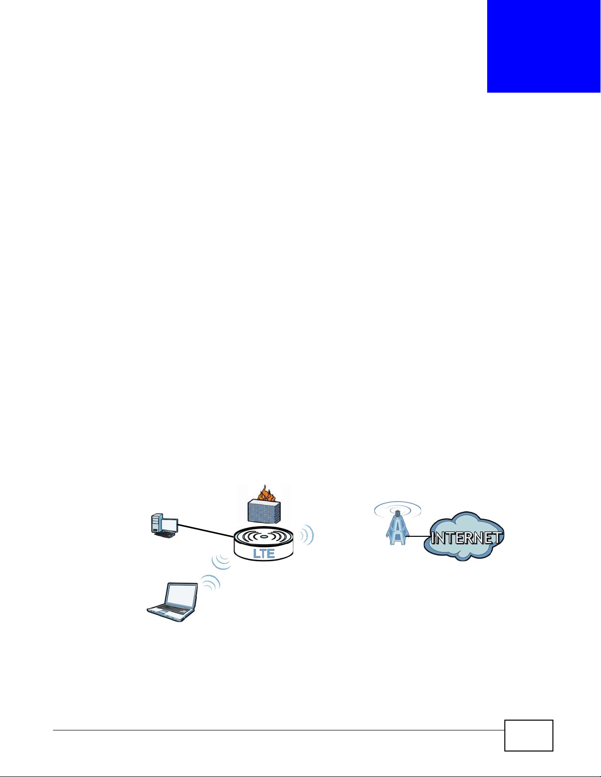
1.2.1 Internet Access
Your LTE Device provides Internet access by connecting to an LTE network wirelessly.
Computers can connect to the LTE Device’s ETHERNET ports.
Figure 1 LTE Device’s Internet Access Application
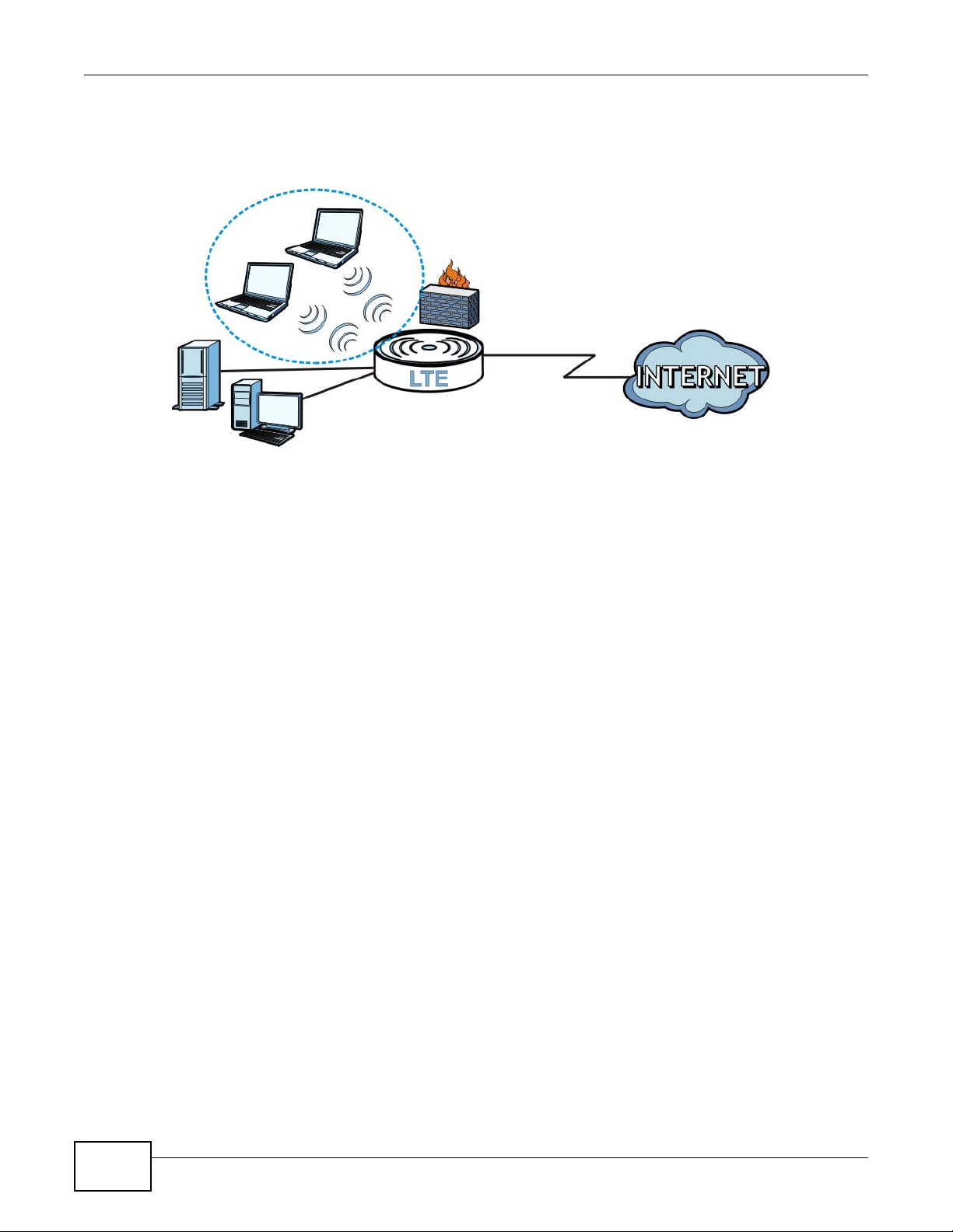
1.2.2 Wireless Connection
By default, the wireless LAN (WLAN) is enabled on the LTE Device. Once Wireless is enabled, IEEE
802.11b/g/n compliant clients can wirelessly connect to the LTE De vice to access network
LTE6101 User’s Guide 13
Page 14
Chapter 1 Introduction
resources. You can set up a wireless network with WPS (WiFi Protected Setup) or manually add a
client to your wireless network.
Figure 2 Wireless Connection Application
1.3 The WLAN Button
You can use the WIRELESS ON/OFF button on top of the device to turn the wireless LAN on or off.
You can also use it to activate WPS in order to quickly set up a wireless network with strong
security.
Turn the Wireless LAN On or Off
1 Make sure the PWR/SYS LED is on (not blinking).
2 Press the WIRELESS ON/OFF button for one second and release it. The WLAN/WPS LED should
change from on to off or vice versa.
Activate WPS
1 Make sure the PWR/SYS LED is on (not blinking).
2 Press the WIRELESS ON/OFF button for more than five seconds and release it. Press the WPS
button on another WPS-enabled device within range of the LTE Device. The WLAN/WPS LED
should flash while the LTE Device sets up a WPS connection with the wireless device.
You must activate WPS in the LTE Device and in another wireless device within two minutes of each
other. See Section 5.7.6 on page 59 for more information.
14
LTE6101 User’s Guide
Page 15
1.4 Ways to Manage the LTE Device
• Web Configurator. This is for management of the LTE Device using a (supported) web browser.
1.5 Good Habits for Managing the LTE Device
Do the following things regularly to make the LTE Device more secure and to manage the LTE
Device more effectively.
• Change the password. Use a password that’s not easy to guess and that consists of different
types of characters, such as numbers and letters.
• Write down the password and put it in a safe place.
• Back up the configuration (and make sure you know how to restore it). Restoring an earlier
working configuration may be useful if the device becomes unstable or even crashes. If you
forget your password to access the Web Configurator, you will have to reset the LTE Device to its
factory default settings. If you backed up an earlier configuration file, you would not have to
totally re-configure the LTE Device. You could simply restore your last configuration. Write down
any information your ISP provides you.
Chapter 1 Introduction
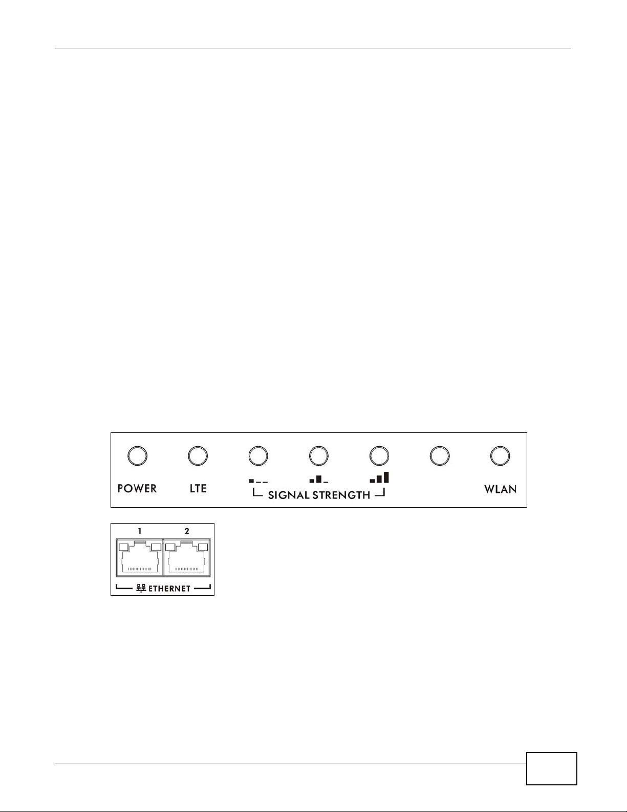
1.6 LEDs (Lights)
The following graphic displays the labels of the LEDs.
Figure 3 LEDs on the Top of the Device
Figure 4 LEDs on the Ethernet Ports
LTE6101 User’s Guide
15
Page 16

Chapter 1 Introduction
None of the LEDs are on if the LTE Device is not receiving power.
Table 1 LED Descriptions (From Left To Right)
LED COLOR STATUS DESCRIPTION
PWR/SYS Green On The LTE Device is receiving power and ready for use.
LTE Green On The LTE Device has an LTE connection on the WAN.
Signal
Strength
Blinking The LTE Device is booting up.
Red On The LTE Device detected an error while self-testing, or there is a
Blinking The LTE Device is upgrading the firmware.
Off The LTE Device is not receiving power.
Blinking The LTE Device is searching for a frequency channel or is performing
Off The LTE Device does not have an LTE connection on the WAN.
No Signal
LEDS
Green Signal 1 OnThe signal strength is less than -90 dBm if signal 1 is on only.
device malfunction.
network entry.
The LTE LEDs display the Received Signal Strength Indication (RSSI)
of the LTE connection. Three signals on at the same time means best
signal quality, two means medium signal quality, and one means low
signal quality.
There is no L T E conn e ct ion .
Signal 2 OnThe signal strength is between -90 dBm and -70 dBm if both signals 1
Signal 3 OnThe signal strength is -70 dBm or greater if three signals are all on.
WLAN Green On The wireless network is activated.
Blinking The LTE Device is communicating with wireless clients.
Orange On The LTE Device is setting up a WPS connection.
Off The wireless network is not activated.
ETHERNET1-2Yellow
(Giga
Ethernet)
Green (Fast
Ethernet)
Off The LTE Device does not have an Ethernet connection with the LAN.
On The LTE Device has a successful 1000 Mbps Ethernet connection with
Blinking The LTE Device is sending or receiving data to/from the LAN at 1000
On The LTE Device has a successful 10/100 Mbps Ethernet connection
Blinking The LTE Device is sending or receiving data to/from the LAN at 10/
Refer to the Quick Start Guide for information on hardware connections.
1.7 The RESET Button
and 2 are on.
a device on the Local Area Network (LAN).
Mbps.
with a device on the Local Area Network (LAN).
100 Mbps.
16
If you forget your password or cannot access the web configurator, you will need to use the RESET
button at the back of the device to reload the factory-default configuration file. This means that y ou
will lose all configurations that you had previously and the passwords will be reset to the defaults.
LTE6101 User’s Guide
Page 17

Chapter 1 Introduction
1 Make sure the POWER LED is on (not blinking).
2 T o set the device back to the factory default settings, press the RESET button for 5 seconds o r until
the POWER LED begins to blink and then release it. When the POWER LED begins to blink, the
defaults have been restored and the device restarts.
LTE6101 User’s Guide
17
Page 18

Chapter 1 Introduction
18
LTE6101 User’s Guide
Page 19
2.1 Overview
The web configurator is an HTML-based management interface that allows easy device setup and
management via Internet browser. Use Internet Explorer 6.0 and later versions, Mozilla Firefox 3
and later versions, or Safari 2.0 and later versions. The recommended screen resolution is 1024 by
768 pixels.
In order to use the web configurator you need to allow:
• Web browser pop-up windows from your device. Web pop-up blocking is enabled by default i n
Windows XP SP (Service Pack) 2.
• JavaScript (enabled by default).
• Java permissions (enabled by default).
CHAPTER 2
Introducing the Web Configurator
See Appendix C on page 197 if you need to make sure these functions are allowed in Internet
Explorer.
2.1.1 Accessing the Web Configurator
1 Make sure your LTE Device hardware is properly connected (refer to the Quick Start Guide).
2 Launch your web browser.
3 Type "192.168.1.1" as the URL.
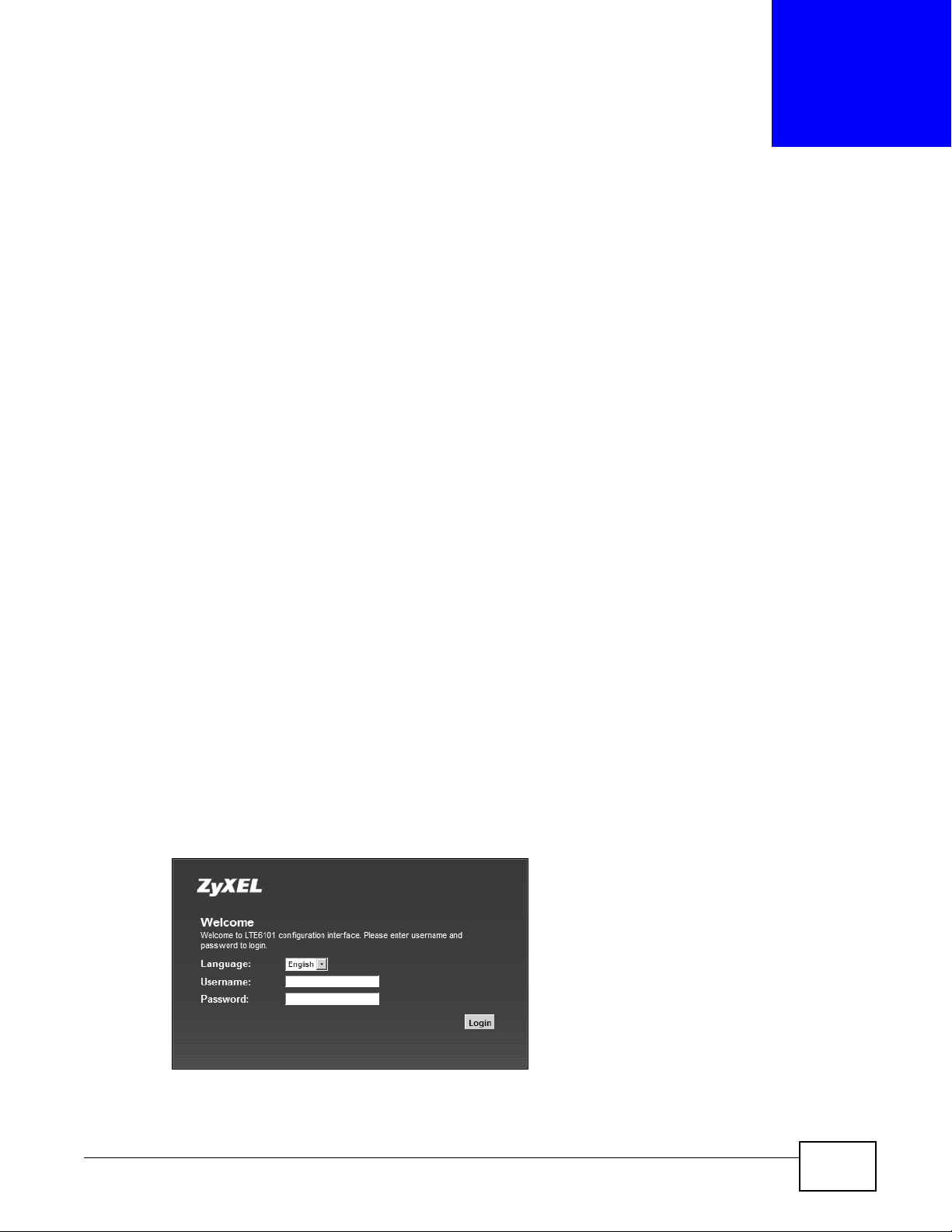
4 A password screen displays. Type “admin” as the default Username and “1234” as the default
password to access the device’s W eb Configur ator. Click Login. If you have changed the password,
enter your password and click Login.
Figure 5 Password Screen
LTE6101 User’s Guide 19
Page 20
Chapter 2 Introdu cing the Web Configurator
Note: For security reasons, the LTE Device automatically logs you out if you do not use
the web configurator for five minutes (default). If this happens, log in again.
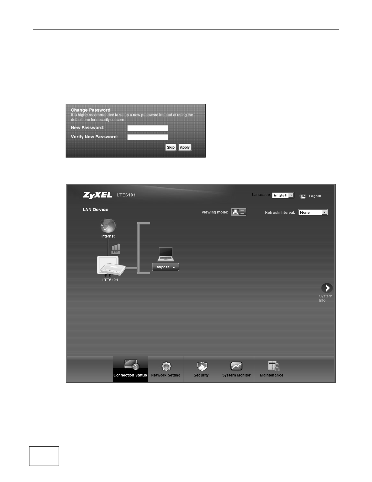
5 The following screen displays if you have not yet changed your password. It is strongly
recommended you change the default password. Enter a new password, retype it to confirm and
click Apply; alternatively click Skip to proceed to the main menu if you do not want to change the
password now.
Figure 6 Change Password Screen
6 The Connection Status screen appears.
Figure 7 Connection Status
7 Click System Info to display the System Info screen, where you can view the LTE Device’s
interface and system information.
20
LTE6101 User’s Guide
Page 21
2.2 The Web Configurator Layout
B
C
A
a
b
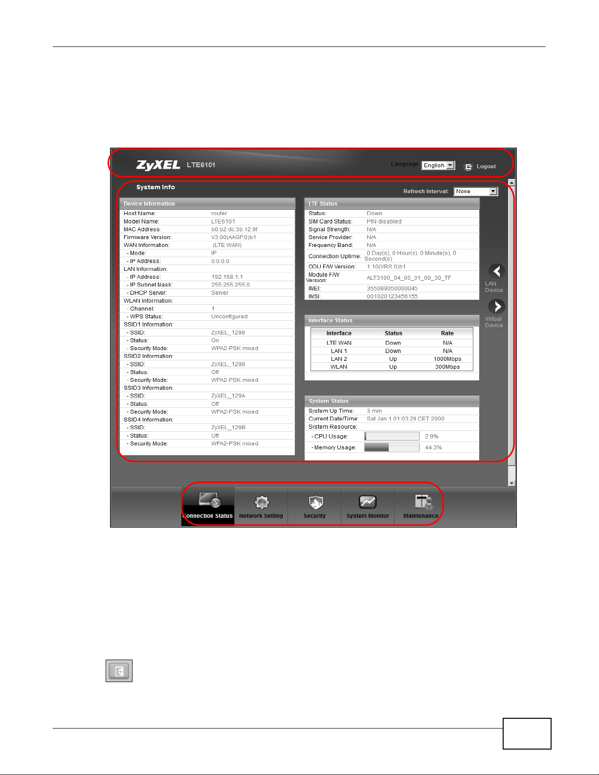
Click Connection Status > System Info to show the following screen. (See Section 3.3 on page
29 for more information.)
Figure 8 Web Configurator Layout
Chapter 2 Introducing the Web Configurator
As illustrated above, the main screen is divided into these parts:
• A - title bar
• B - main window
• C - navigation panel
2.2.1 Title Bar
The title bar shows the following icon in the upper right corner.
LTE6101 User’s Guide
21
Page 22
Chapter 2 Introdu cing the Web Configurator
Click this icon to log out of the web configurator.
2.2.2 Main Window
The main window displays information and configuration fields. It is discussed in the rest of this
document.
After you click System Info on the Connection Status screen, the System Info screen is
displayed. See Chapter 3 on page 29 for more information about the System Info screen.
If you click LAN Device on the System Info screen (a in Figure 8 on page 21), the Connection
Status screen appears. See Chapter 3 on page 27 for more information about the Connection
Status screen.
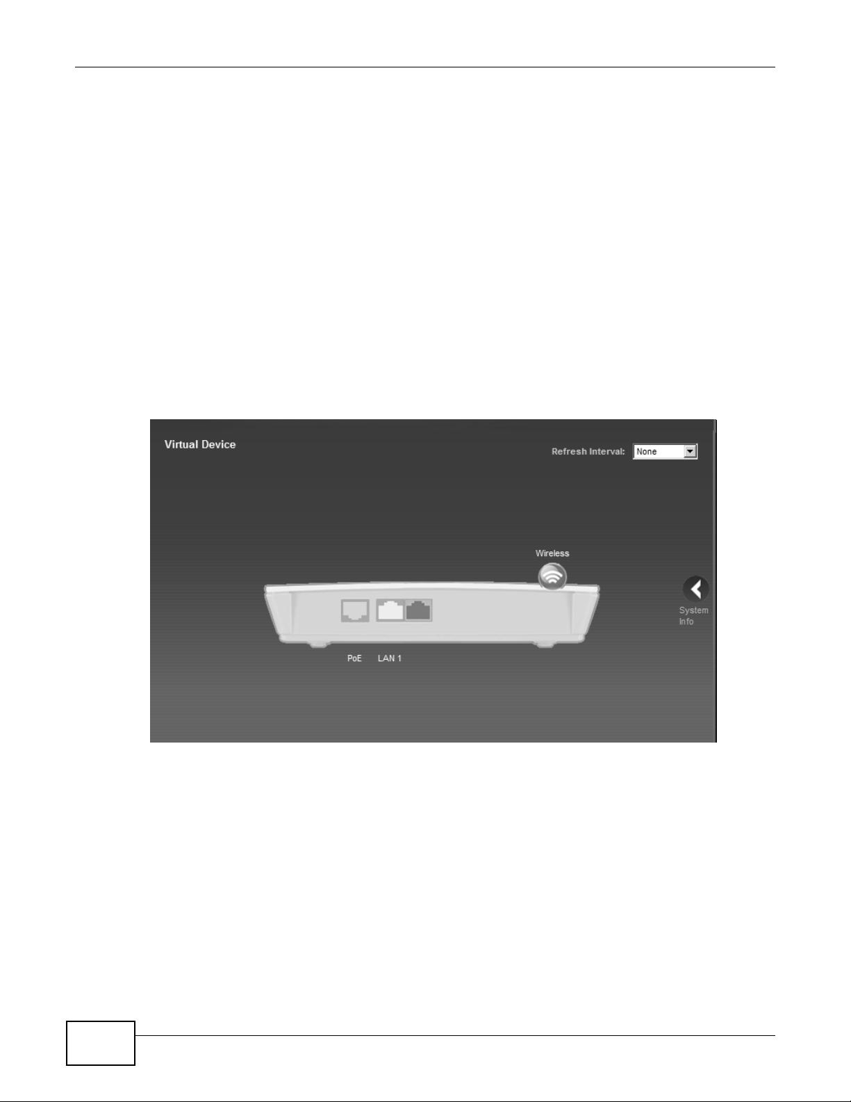
If you click Virtual Device on the System Info screen (b in Figure 8 on page 21), a visual graphic
appears, showing the connection status of the LTE Device’s ports. The connected ports are in color
and disconnected ports are gray.
Figure 9 Virtual Device
2.2.3 Traffic Status
Use the Maintenance > Traffic Status screens to look at network traffic status and statistics of
the WAN, LAN interfaces and NAT. See Chapter 19 on page 137 for more information.
2.2.4 User Account
Use the Maintenance > User Accounts screen to configure system password for different user
accounts. See Chapter 17 on page 133 for more information.
22
LTE6101 User’s Guide
Page 23

2.2.5 Navigation Panel
Use the menu items on the navigation panel to open screens to configure LTE Device features. The
following table describes each menu ite m.
Table 2 Navigation Panel Summary
LINK TAB FUNCTION
Connection Status This screen shows the network status of the LTE Device and
Network Setting
Broadband Broadband Use this screen to view and modify your WAN interface.
SIM Use this screen to enter the PIN of your SIM card.
Wireless General Use this screen to turn the wireless connection on or off, specify the
More AP Use this screen to configure multiple BSSs on the LTE Device.
WPS Use this screen to use WPS (Wi-Fi Protected Setup) to establish a
WMM Use this screen to enable or disable Wi-Fi MultiMedia (WMM).
Scheduling Use this screen to configure when the LTE Device enables or disables
Home
Networking
Static Route Static Route Use this screen to view and set up static routes on the LTE Device.
QoS General Use this screen to enable QoS and decide allowable bandwidth using
NAT Port Forwarding Use this screen to make your local servers visible to the outside
Dynamic DNS Dynamic DNS Use this screen to allow a static hostname alias for a dynamic IP
Security
Firewall General Use this screen to activate/deactivate the firewall.
LAN Setup Use this screen to configure LAN TCP/IP settings, and other advanced
Static DHCP Use this screen to assign specific IP addresses to individual MAC
UPnP Use this screen to enable the UPnP function.
Queue Setup
Class Setup Use this screen to set up classifiers to sort traffic into different flows
Monitor
DMZ Use this screen to configure the IP address of the LTE Device’s DMZ
Sessions Use this screen to limit the number of NAT sessions a single client can
Services Use this screen to view and configure services.
Access Control Use this screen to view and configure filter rules for incoming and
DoS Use this screen to activate/deactivate Denial of Service (DoS)
Chapter 2 Introducing the Web Configurator
computers/devices connected to it.
SSID(s) and configure the wireless LAN settings and WLAN
authentication/security settings.
wireless connection.
the wireless LAN.
properties.
addresses.
QoS.
Use this screen to configure QoS queue assignment.
and assign priority and define actions to be performed for a classified
traffic flow.
Use this screen to view each queue’s statistics.
world.
interface.
establish.
address.
outgoing traffic.
protection.
LTE6101 User’s Guide
23
Page 24

Chapter 2 Introdu cing the Web Configurator
Table 2 Navigation Panel Summary (continued)
LINK TAB FUNCTION
MAC Filter MAC Filter Use this screen to allow specific devices t o access the LTE Device.
Parental
Control
VPN Setup Use this screen to configure IPSec VPN connections.
System Monitor
Log System Log Use this screen to view the system logs for the categories that you
Traffic Status WAN Use this screen to view the status of all network traffic going through
Maintenance
Users Account Users Account Use this screen to configure the passwords your user accounts.
Remote MGMT Remote MGMT Use this screen to enable specific traffic directions for network
System System Use this screen to configure the LTE Device’s name, domain name,
Time Setting Time Setting Use this screen to change your LTE Device’s time and date.
Log Setting Log Setting Use this screen to select which logs and/or immediate alerts your
Firmware
Upgrade
Backup/
Restore
Reboot Reboot Use this screen to reboot the LTE Device without turning the power
Diagnostic Ping/TraceRoute Use this screen to test the connections to other devices.
Parental Control Use this screen to define time periods and days during which the LTE
Monitor Use this screen to view IPSec VPN connection status.
LAN Use this screen to view the status of all network traffic going through
NAT Use this screen to view the status of NAT sessions on the LTE Device.
Firmware
Upgrade
Backup/Restore Use this screen to backup and restore your device’s configuration
Device performs parental control and/or block web sites with the
specific URL.
select.
the WAN port of the LTE Device.
the LAN ports of the LTE Device.
services.
management inactivity time-out.
device is to record. You can also set it to e-mail the logs to you.
Use this screen to upload firmware to your device.
(settings) or reset the factory default settings.
off.
24
LTE6101 User’s Guide
Page 25

PART II
Technical Reference
The appendices provide general information. Some details may not apply to your LTE Device.
25
Page 26

26
Page 27

CHAPTER 3
Connection Status and System Info
3.1 Overview
After you log into the web configurator, the Connection Status screen appears. This shows the
network connection status of the LTE Device and clients connected to it.
Use the System Info screen to look at the current status of the device, system resources,
interfaces (LAN, WAN).
If you click Virtual Device on the System Info screen, a visual graphic appears, showing the
connection status of the LTE Device’s ports. See Section 2.2.2 on page 22 for more information.
3.2 The Connection Status Screen
Use this screen to view the network connection status of the device and its clients. A warning
message appears if there is a connection problem.
LTE6101 User’s Guide 27
Page 28
Chapter 3 Connection Status and System Info
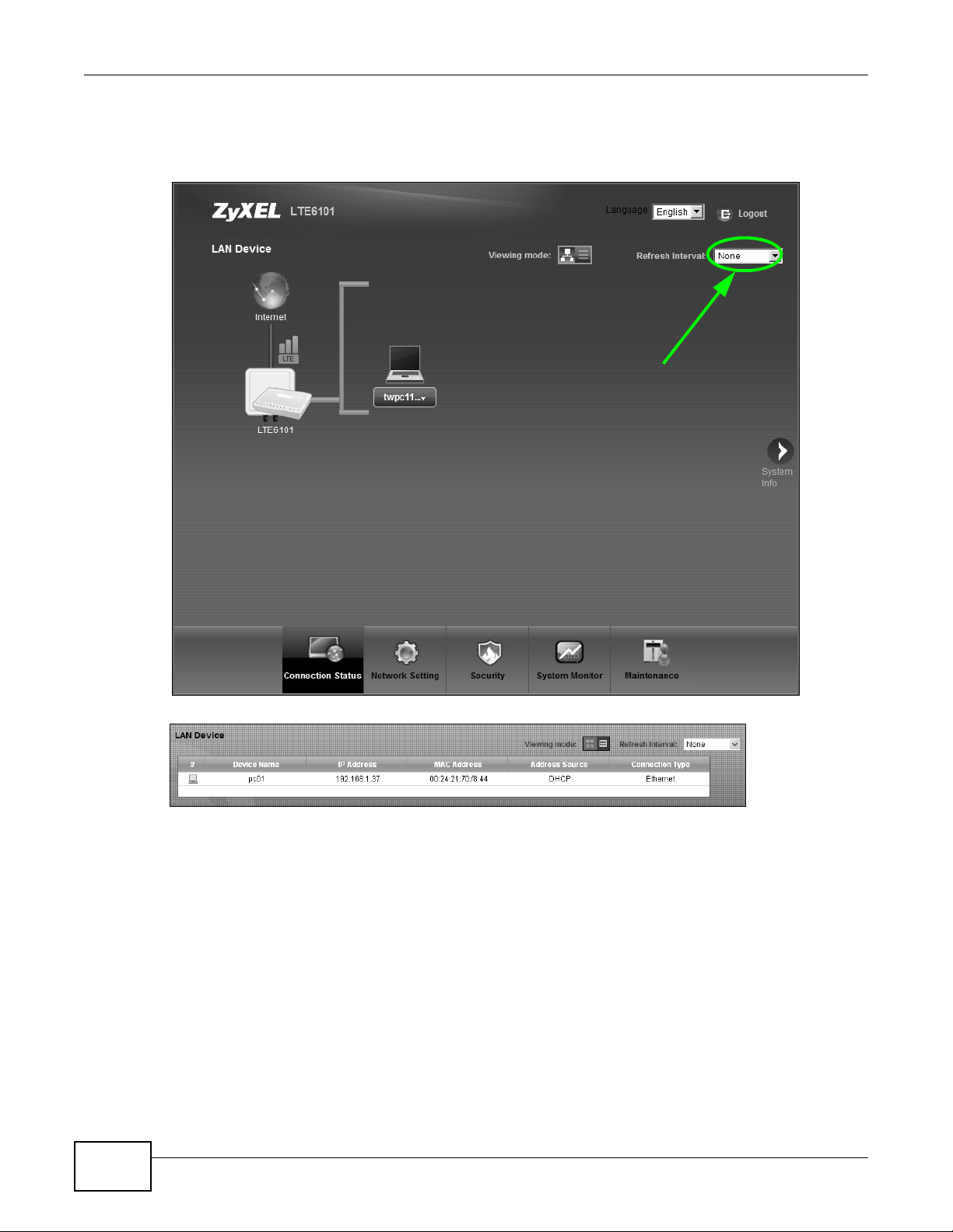
If you prefer to view the status in a list, click List View in the Viewing mode selection box. You
can configure how often you want the LTE Device to update this screen in Refresh Interval.
Figure 10 Connection Status: Icon View
Figure 11 Connection Status: List View
In Icon View, if you want to view information about a client, click the client’ s name and Info . Click
the IP address if you want to change it. If you want to change the name or icon of the client, click
Change name/icon.
In List View, you can also view the client’s information.
28
LTE6101 User’s Guide
Page 29
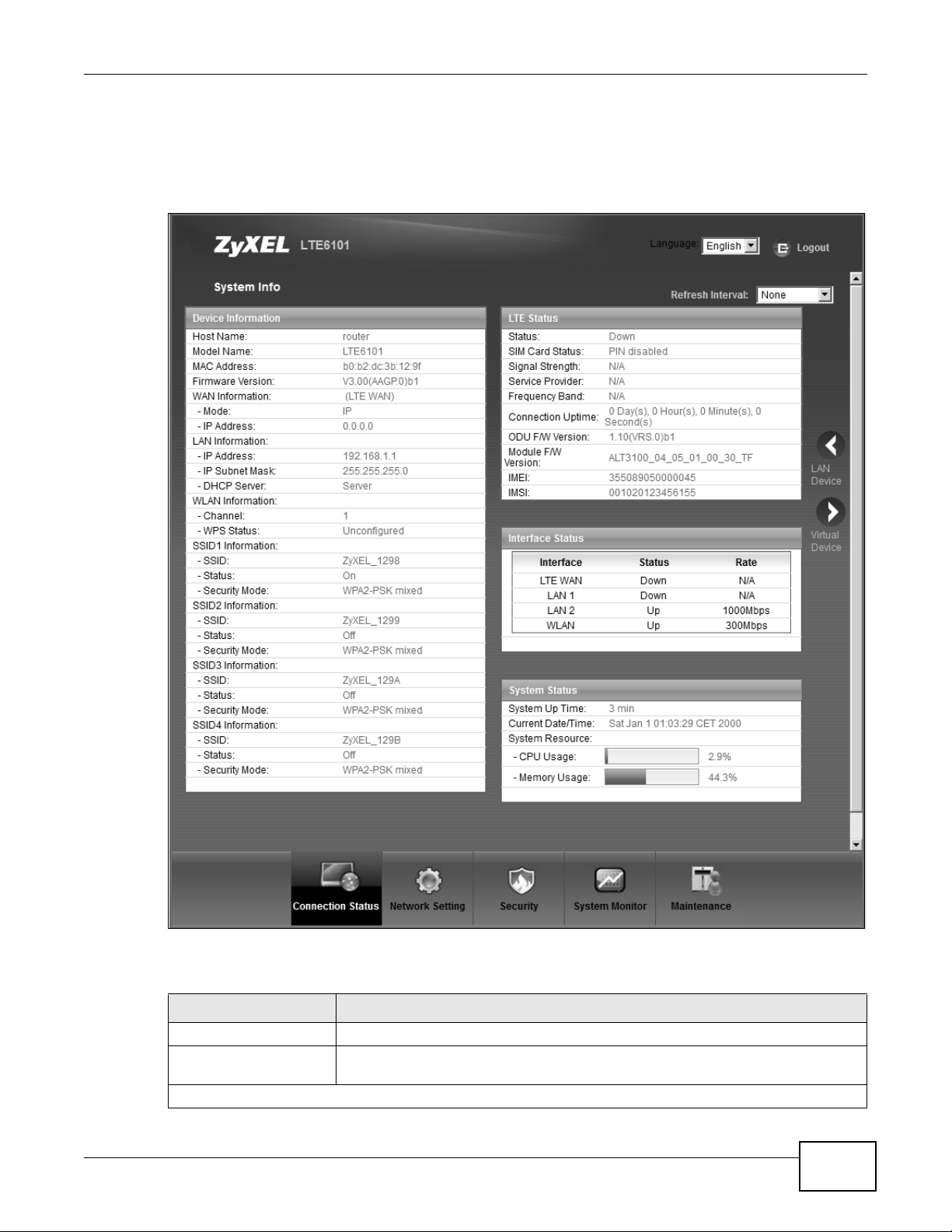
3.3 The System Info Screen
Click Connection Status > System Info to open this screen.
Figure 12 System Info Screen
Chapter 3 Co nnection Status and System Info
Each field is described in the following table.
Table 3 System Info Screen
LABEL DESCRIPTION
Language Select the web configurator language from the drop-down list box.
Refresh Interval Select how often you want the LTE Device to update this screen from the drop-
Device Information
LTE6101 User’s Guide
down list box.
29
Page 30

Chapter 3 Connection Status and System Info
Table 3 System Info Screen (continued)
LABEL DESCRIPTION
Host Name This field displays the LTE Device system name. It is used for identification. You
can change this in the Maintenance > System screen’s Host Name field.
Model Name This is the model name of your device.
MAC Address This is the MAC (Media Access Control) or Ethernet address unique to your LTE
Device.
Software Version This field displays the current version of the firmware inside the device. It also
WAN Information
Mode This is the method of encapsulation used by your ISP.
IP Address This field displays the current IP address of the LTE Device in the WAN.
LAN Information
IP Address This field displays the current IP address of the LTE Device in the LAN.
IP Subnet Mask This field displays the current subnet mask in the LAN.
DHCP Server This field displays what DHCP services the LTE Device is providing to the LAN.
WLAN Information
Channel This is the channel n umber used by the LTE Device now.
WPS Status Configured displays when a wireless client has connected to the LTE Device or
SSID (1~4) Information
SSID This is the descriptive name used to identify the LTE Device in the wireless LAN.
Status This shows whether or not the SSID is enabled (on).
Security Mode This displays the type of security the LTE Device is using in the wireless LAN.
LTE Status
Status This displays 4G LTE if there is an LTE connection, otherwise, it displays Down.
SIM Card Status This displays the SIM card status:
shows the date the firmware version was created. Go to the Maintenance >
Firmware Upgrade screen to change it.
Choices are:
Server - The LTE Device is a DHCP server in the LAN. It assigns IP addresses to
other computers in the LAN.
None - The LTE Device is not providing any DHCP services to the LAN.
WPS is enabled and wireless or wireless security settings have been configured.
Unconfigured displays if WPS is disabled or wireless security settings have not
been configured.
30
PIN disabled - SIM card has no PIN code security.
PIN required - SIM card has PIN code security, but you didn't enter PIN code yet.
PIN verified - SIM card has PIN code security, and you entered the correct PIN
code.
PIN locked - you entered an incorrect PIN code more than 10 times, so SIM card
has been locked; call ISP for PUK (Pin Unlock Key) to unlock SIM card.
SIM card locked call operator - PUK (Pin Unlock Key) failed, so SIM card has
been locked.
No SIM Card - you have not inserted a SIM card.
SIM Card Error - other SIM card error.
Signal Strength This displays the strength of the LTE connection that the LTE Device has with the
base station which is also known as eNodeB or eNB.
LTE6101 User’s Guide
Page 31

Chapter 3 Co nnection Status and System Info
Table 3 System Info Screen (continued)
LABEL DESCRIPTION
Service Provider This displays the service provider’s name of the connected LTE network.
Frequency Band This displays LTE if there is an LTE connection.
Connection Uptime This displays how long the LTE connection has been available since it was last
established successfully.
ODU F/W Version This displays the firmware version of the outdoor unit.
Module F/W Version This displays the firmware version of LTE module.
IMEI This displays the LTE Device’s International Mobile Equipment Identity number
(IMEI). An IMEI is a unique ID used to identify a mobile device.
IMSI This displays the International Mobile Subscriber Identity (IMSI) of the SIM card
Interface Status
Interface This column displays each interface the LTE Device has.
Status This field indicates whether or not the LTE Device is using the interface.
Rate For the LTE WAN interface, this displays 4G LTE if there is an LTE connection.
System Status
System Up Time This field displays how long the LTE Device has been running since it last started
Current Date/Time This field displays the current date and time in the LTE Device. You can change this
System Resource
CPU Usage This field displays what percentage of the LTE Device’s processing ability is
Memory Usage This field displays what percentage of the LTE Device’s memory is currently used.
inserted in the outdoor unit. An IMSI is a unique ID used to identify a mobile
subscriber in a mobile network.
For the LTE WAN interface, this field displays Up when the LTE Device is connected
to an LTE network and Down when the LTE Device does not have an LTE
connection.
For the LAN interface, this field displays Up when the LTE Device is using the
interface and Down when the LTE Device is not using the interface.
For the LAN interface, this displays the port speed and duplex setting.
up. The LTE Device starts up when you plug it in, when you restart it
(Maintenance > Reboot), or when you reset it (see Section 1.7 on page 16).
in Maintenance > Time Setting.
currently used. When this percentage is close to 100%, the LTE Device is running
at full load, and the throughput is not going to improve anymore. If you want some
applications to have more throughput, you should turn off other applications.
Usually , this percentage should not increase much. If memory usage does get close
to 100%, the LTE Device is probably becoming unstable, and you should restart
the device. See Chapter 23 on page 147, or turn off the device (unplug the power)
for a few seconds.
LTE6101 User’s Guide
31
Page 32

Chapter 3 Connection Status and System Info
32
LTE6101 User’s Guide
Page 33

4.1 Overview
WAN
LAN
This chapter discusses the LTE Device’s Broadband screens. Use these screens to configure your
LTE Device for Internet access.
A WAN (Wide Area Network) connection is an outside connection to another network or the
Internet. It connects your private networks, such as a LAN (Local Area Network) and other
networks, so that a computer in one location can communicate with computers in other locations.
This LTE Device supports LTE connection for the WAN only.
Figure 13 LAN and WAN
CHAPTER 4
Broadband
4.1.1 What You Can Do in this Chapter
•Use the Broadband screen to view or edit an L TE WAN interface. Y o u can also configure the W AN
settings on the LTE Device for Internet access (Section 4.2 on page 34).
•Use the SIM screen to enter the PIN of your SIM card (Section 4.3 on page 36).
4.1.2 What You Need to Know
The following terms and concepts may help as you read this chapter.
LTE6101 User’s Guide 33
Page 34

Chapter 4 Broadband
WAN IP Address
The WAN IP address is an IP address for the L TE Device, which makes it accessible from an outside
network. It is used by the LTE Device to communicate with other devices in other networks. It can
be static (fixed) or dynamically assigned by the ISP each time the LTE Device tries to access the
Internet.
If your ISP assigns you a static WAN IP address, they should also assign you the subnet mask and
DNS server IP address(es).
APN
Access Point Name (APN) is a unique string which indicates an LTE network. An APN is required for
LTE stations to enter the LTE network and then the Internet.
4.1.3 Before You Begin
You may need to know your Internet access settings such as LTE APN, WAN IP address and SIM
card’s PIN code if the INTERNET light on your LTE Device is off. Get this information from your
service provider.
4.2 The Broadband Screen
The LTE Device must have a WAN interface to allow users to use the LTE connection to access the
Internet. Use the Broadband screen to view or modify a WAN interface.
Click Network Setting > Broadband. The following screen opens.
Figure 14 Network Setting > Broadband
The following table describes the fields in this screen.
Table 4 Network Setting > Broadband
LABEL DESCRIPTION
Internet Setup
Name This is the service name of the connection.
APN This is the name of the LTE network to which the LTE Device will connect.
IPv6/IPv4 Mode This shows whether the connection uses IPv6 or IPv4.
34
LTE6101 User’s Guide
Page 35

Table 4 Network Setting > Broadband (continued)
LABEL DESCRIPTION
NAT This shows whether NAT is activated or not for this connection. NAT is not available
when the connection uses the bridging service.
Modify Click the Edit icon to configure the connection.
Click the Delete icon to delete this connection from the Device. A window displays
asking you to confirm that you want to delete the connection.
4.2.1 Edit Internet Connection
Use this screen to configure a WAN connection.
Click the Edit icon next to the LTE connection, the screen displays as shown next.
Figure 15 Broadband Edit
Chapter 4 Broadband
The following table describes the fields in this screen.
Table 5 Broadband Edit
LABEL DESCRIPTION
Name Specify the name for this WAN interface.
APN Enter the Access Point Name (APN) of an LTE network, which your service provider gave you.
Dial String Enter the dial string for the ISP.
MTU
NAT Enable Select this to activate NAT on the WAN.
Apply as
Default
Gateway
LTE6101 User’s Guide
The Maximum Transmission Unit (MTU) defines the size of the largest packet allowed on an
interface or connection. Enter the MTU for this WAN interface in this field.
Select this option to have the LTE Device use the WAN interface of this connection as the
system default gateway.
35
Page 36

Chapter 4 Broadband
Table 5 Broadband Edit (continued)
LABEL DESCRIPTION
Apply Click Apply to save your changes.
Back Click Back to return to the previous screen.
4.3 The SIM Screen
Use the SIM screen to enter the PIN of your SIM card.
If the wrong PIN code is entered 3 times, it will cause the SIM card to be
locked.
Click Network Setting > Broadband > SIM. The following screen opens.
Figure 16 SIM
The following table describes the fields in this screen.
Table 6 SIM
LABEL DESCRIPTION
PIN Enter the PIN of your SIM card.
Apply Click Apply to save your changes.
Cancel Click Cancel to return to the previous screen without saving.
4.3.1 PUK Code Screen
If the SIM card is locked, use this screen to enter the PUK code.
36
LTE6101 User’s Guide
Page 37

Chapter 4 Broadband
Note: You may have to ask the service provider for a PUK code to unlock the SIM card.
Figure 17 PUK Code
The following table describes the fields in this screen.
Table 7 PUK Code
LABEL DESCRIPTION
PUK code Enter the PUK (Pin Unlock Key) code to unlock the SIM card.
New PIN code Enter the new PIN code for the SIM card.
Apply Click Apply to save your changes.
Cancel Click Cancel to return to the previous screen without saving.
4.4 Technical Reference
The following section contains additional technical information about the LTE Device features
described in this chapter.
Encapsulation
Be sure to use the encapsulation method required by your ISP. The LTE Device supports the
following methods:
IP Address Assignment
A static IP is a fixed IP that your ISP gives you. A dynamic IP is not fixed; the ISP assigns you a
different one each time. The Single User Account feature can be enabled or disabled if you have
either a dynamic or static IP. However the encapsulation method assigned influences your choices
for IP address and default gateway.
LTE6101 User’s Guide
37
Page 38

Chapter 4 Broadband
DNS Server Address Assignment
Use Domain Name System (DNS) to map a domain name to its corresponding IP address and vice
versa. The DNS server is ex tremely important be ca use without it, you m ust know the IP address of
a computer before you can access it.
The LTE Device can get the DN S server addresses in the following ways.
1 The ISP tells you the DNS server addresses, usually in the form of an information sheet, when you
sign up. If your ISP gives you DNS server addresses, manually enter them in the DNS server fields.
2 If your ISP dynamically assigns the DNS server IP addresses (along with the LTE Device’s WAN IP
address), set the DNS server fields to get the DNS server address from the ISP.
LTE Frequency Band Table
See the following table for the frequency bands used in LTE wireless technologies.
Table 8 LTE Wireless Technologies
UPLINK (UL) OPERATING BAND
DOWNLINK (DL) OPERATING BAND
BAND
BASE STATION RECEIVE
CPE TRANSMIT
BASE STATION TRANSMIT
CPE RECEIVE
DUPLEX
MODE
UL (LOW - HIGH) DL (LOW - HIGH)
1 1920 MHz – 1980 MHz 2110 MHz – 2170 MHz FDD
2 1850 MHz – 1910 MHz 1930 MHz – 1990 MHz FDD
3 1710 MHz – 1785 MHz 1805 MHz – 1880 MHz FDD
4 1710 MHz – 1755 MHz 2110 MHz – 2155 MHz FDD
5 824 MHz – 849 MHz 869 MHz – 894MHz FDD
6 830 MHz – 840 MHz 875 MHz – 885 MHz FDD
7 2500 MHz – 2570 MHz 2620 MHz – 2690 MHz FDD
8 880 MHz – 915 MHz 925 MHz – 960 MHz FDD
9 1749.9 MHz – 1784.9 MHz 1844.9 MHz – 1879.9 MHz FDD
10 1710 MHz – 1770 MHz 2110 MHz – 2170 MHz FDD
11 1427.9 MHz – 1447.9 MHz 1475.9 MHz – 1495.9 MHz FDD
12 699 MHz – 716 MHz 729 MHz – 746 MHz FDD
13 777 MHz – 787 MHz 746 MHz – 756 MHz FDD
14 788 MHz – 798 MHz 758 MHz – 768 MHz FDD
15 Reserved Reserved FDD
16 Reserved Reserved FDD
17 704 MHz – 716 MHz 734 MHz – 746 MHz FDD
18 815 MHz – 830 MHz 860 MHz – 875 MHz FDD
19 830 MHz – 845 MHz 875 MHz – 890 MHz FDD
20 832 MHz – 862 MHz 791 MHz – 821 MHz FDD
21 1447.9 MHz – 1462.9 MHz 1495.9 MHz – 1510.9 MHz FDD
...
24 1626.5 MHz – 1660.5 MHz 1525 MHz – 1559 MHz FDD
38
LTE6101 User’s Guide
Page 39

Table 8 LTE Wireless Technologies (continued)
UPLINK (UL) OPERATING BAND
DOWNLINK (DL) OPERATING BAND
Chapter 4 Broadband
BAND
BASE STATION RECEIVE
CPE TRANSMIT
BASE STATION TRANSMIT
CPE RECEIVE
DUPLEX
MODE
UL (LOW - HIGH) DL (LOW - HIGH)
...
33 1900 MHz – 1920 MHz 1900 MHz – 1920 MHz TDD
34 2010 MHz – 2025 MHz 2010 MHz – 2025 MHz TDD
35 1850 MHz – 1910 MHz 1850 MHz – 1910 MHz TDD
36 1930 MHz – 1990 MHz 1930 MHz – 1990 MHz TDD
37 1910 MHz – 1930 MHz 1910 MHz – 1930 MHz TDD
38 2570 MHz – 2620 MHz 2570 MHz – 2620 MHz TDD
39 1880 MHz – 1920 MHz 1880 MHz – 1920 MHz TDD
40 2300 MHz – 2400 MHz 2300 MHz – 2400 MHz TDD
41 2496 MHz 2690 MHz 2496 MHz 2690 MHz TDD
42 3400 MHz – 3600 MHz 3400 MHz – 3600 MHz TDD
43 3600 MHz – 3800 MHz 3600 MHz – 3800 MHz TDD
Note 1: Band 6 is not applicable
LTE6101 User’s Guide
39
Page 40

Chapter 4 Broadband
40
LTE6101 User’s Guide
Page 41

5.1 Overview
This chapter describes the LTE Device’s Network Setting > Wireless screens. Use these screens
to set up your LTE Device’s wireless connection.
5.1.1 What You Can Do in this Chapter
•Use the General screen to enable the Wireless LAN, enter the SSID and select the wireless
security mode (Section 5.2 on page 43).
•Use the More AP screen to set up multiple wireless networks on your LTE Device (Section 5.3 on
page 49).
•Use the WPS screen to enable or disable WPS, view or generate a security PIN (Personal
Identification Number) (Section 5.4 on page 51).
•Use the WMM screen to enable Wi-Fi MultiMedia (WMM) to ensure quality of service in wireless
networks for multimedia applications (Section 5.5 on page 52).
•Use the Scheduling screen to schedule a time period for the wireless LAN to operate each day
(Section 5.6 on page 54).
CHAPTER 5
Wireless
You don’t necessarily need to use all these screens to set up your wireless connection. For example,
you may just want to set up a network name, a wireless radio channel and some security in the
General screen.
5.1.2 Wireless Network Overview
Wireless networks consist of wireless clients, access points and bridges.
• A wireless client is a radio connected to a user’s computer.
• An access point is a radio with a wired connection to a network, which can connect with
numerous wireless clients and let them access the network.
• A bridge is a radio that relays communications between access points and wireless clients,
extending a network’s range.
Traditionally, a wireless network operates in one of two ways.
• An “infrastructure” type of network has one or more access points and one or more wireless
clients. The wireless clients connect to the access points.
• An “ad-hoc” type of network is one in which there is no access point. Wireless clients connect to
one another in order to exchange information.
LTE6101 User’s Guide 41
Page 42

Chapter 5 Wireless
The following figure provides an example of a wireless network.
Figure 18 Example of a Wireless Network
The wireless network is the part in the blue circle. In this wireless network, devices A and B use the
access point (AP) to interact with the other devices (such as the printer) or with the Internet. Your
LTE Device is the AP.
Every wireless network must follow these basic guidelines.
• Every device in the same wireless network must use the same SSID.
The SSID is the name of the wireless network. It stands for Service Set IDentifier.
• If two wireless networks overlap, they should use a different channel.
Like radio stations or television channels, each wireless network uses a specific channel, or
frequency, to send and receive information.
• Every device in the same wireless network must use security compatible with the AP.
• Security stops unauthorized devices from using the wireless network. It can also protect the
information that is sent in the wireless network.
Radio Channels
In the radio spectrum, there are certain frequency bands allocated for unlicensed, civilian use. For
the purposes of wireless networking, these bands are divided into numerous channels. This allows a
variety of networks to exist in the same place without interfering with one another. When you
create a network, you must select a channel to use.
Since the available unlicensed spectrum varies from one country to another, the number of
available channels also varies.
42
A channel is the radio frequency(ies) used by wireless devices to transmit and receive data.
Channels available depend on your geographical area. You may have a choice of channels (for your
region) so you should use a channel different from an adjacent AP (access point) to reduce
interference. Interference occurs when radio signals from different access points overlap causing
interference and degrading performance.
LTE6101 User’s Guide
Page 43

Adjacent channels partially overlap however. To avoid interference due to overlap, your AP should
be on a channel at least five channels away from a channel that an adjacent AP is using. For
example, if your region has 11 channels and an adjacent AP is using channel 1, then you need to
select a channel between 6 or 11.
5.1.3 Before You Begin
Before you start using these screens, ask yourself the following questions. See Section 5.7 on page
54 if some of the terms used here do not make sense to you.
• What wireless standards do the other wireless devices support (IEEE 802.11g, for example)?
What is the most appropriate standard to use?
• What security options do the other wireless devices support (WPA-PSK, for example)? What is
the best one to use?
• Do the other wireless devices support WPS (Wi-Fi Protected Setup)? If so, you can set up a wellsecured network very easily.
Even if some of your devices support WPS and some do not, you can use WPS to set up your
network and then add the non-WPS devices manually, although this is somewhat more
complicated to do.
• What advanced options do you want to configure, if any? If you want to configure advanced
options, ensure that you know precisely what you want to do. If you do not want to configure
advanced options, leave them alone.
Chapter 5 Wireless
5.2 The Wireless General Screen
Use this screen to enable the Wireless LAN, enter the SSID and select the wireless security mode.
Note: If you are configuring the LTE Device from a computer connected to the wireles s
LAN and you change the LTE Device’s SSID or security settings, you will lose your
wireless connection when you press Apply to confirm. You must then change the
wireless settings of your computer to match the LTE Device’s new settings.
LTE6101 User’s Guide
43
Page 44

Chapter 5 Wireless
Click Network Setting > Wireless to open the General screen. Select the Enable Wireless LAN
checkbox to show the Wireless configurations.
Figure 19 Network Setting > Wireless > General
The following table describes the labels in this screen.
Table 9 Network > Wireless LAN > General
LABEL DESCRIPTION
Wireless Network Setup
Wireless Select the Enable Wireless LAN check box to activate the wireless LAN.
Wireless Network Settings
Wireless
Network Name
(SSID)
Hide SSID Select this check box to hide the SSID in the outgoing beacon frame so a station cannot
BSSID This shows the MAC address of the wireless interface on the LTE Device when wireless LAN
Mode Select This makes sure that only compliant WLAN devices can associate with the LTE Device.
The SSID (Service Set IDentity) identifies the service set with which a wireless device is
associated. Wireless devices associating to the access point (AP) must have the same SSID.
Enter a descriptive name (up to 32 English keyboard characters) for the wireless LAN.
obtain the SSID through scanning using a site survey tool.
is enabled.
Select 802.11b/g/n to allow IEEE802.11b, IEEE802.11g and IEEE802.11n compliant
WLAN devices to associate with the LTE Device. The transmission rate of your LTE Device
might be reduced.
Select 802.11b/g to allow both IEEE802.11b and IEEE802.11g compliant WLAN devices to
associate with the LTE Device. The transmission rate of your LTE Device might be reduced.
Select 802.11g Only to allow only IEEE 802.11g compliant WLAN devices to associate with
the LTE Device. Select 802.11n only in 2.4G band to allow only IEEE 802.11n compliant
WLAN devices with the same frequency range (2.4 GHz) to associate with the LTE Device.
44
LTE6101 User’s Guide
Page 45

Chapter 5 Wireless
Table 9 Network > Wireless LAN > General (continued)
LABEL DESCRIPTION
Channel
Selection
Operating
Channel
Security Level
Security Mode Select Basic or More Secure to add security on this wireless network. The wireless clients
Apply Click Apply to save your changes bac k to the LTE Device.
Cancel Click Cancel to restore your previously saved settings.
Set the channel depending on your particular region.
Select a channel or use Auto to have the LTE Device automatically determine a channel to
use. If you are having problems with wireless interference, changing the channel may help.
T ry to use a channel that is as many channels away from any channels use d by ne ighborin g
APs as possible. The channel number which the LTE Device is currently using then displays
in the Operating Channel field.
This is the channel currently being used by your AP.
which want to associate to this network must have same wireless security settings as the
LTE Device. When you select to use a security, additional options appears in this screen.
Or you can select No Security to allow any client to associate this network without an y data
encryption or authentication.
See the following sections for more details about wireless security modes.
5.2.1 No Security
Select No Security to allow wireless stations to communicate with the access points without any
data encryption or authentication.
Note: If you do n ot enable any wi r eless security on your LTE Device, your netwo rk is
accessible to any wireless networking device that is within range.
Figure 20 Wireless > General: No Security
The following table describes the labels in this screen.
Table 10 Wireless > General: No Security
LABEL DESCRIPTION
Security Level Choose No Security from the sliding bar.
5.2.2 Basic (Static WEP/Shared WEP Encryption)
WEP encryption scrambles the data transmitted between the wireless stations and the access points
(AP) to keep network communications private. Both the wireless stations and the access points
must use the same WEP key.
There are two types of WEP authentication namely, Open System (Static WEP) and Shared Key
(Shared WEP).
LTE6101 User’s Guide
45
Page 46

Chapter 5 Wireless
Open system is implemented for ease-of-use and when security is not an issue. The wireless station
and the AP or peer computer do not share a secret key. Thus the wireless stations can associate
with any AP or peer computer and listen to any transmitted data that is not encrypted.
Shared key mode involves a shared secret key to authenticate the wireless station to the AP or peer
computer. This requires you to enable the wireless LAN security and use same settings on both the
wireless station and the AP or peer computer.
In order to configure and enable WEP encryption, click Network Settings > Wireless to display
the General screen. Select Basic as the security level. Then select Static WEP or Shared WEP
from the Security Mode list.
Figure 21 Wireless > General: Basic (Static WEP/Shared WEP)
The following table describes the labels in this screen.
Tab le 11 Wireless > General: Basic (Static WEP/Shared WEP)
LABEL DESCRIPTION
Security Mode Choose Static WEP or Shared WEP from the drop-down list box.
• Select Static WEP to have the LTE Device allow association with wireless clients that
use Open System mode. Data transfer is encrypted as long as the wireless client has the
correct WEP key for encryption. The LTE Device authenticates wireless clients using
Shared Key mode that have the correct WEP key.
• Select Shared WEP to have the L T E Device authenti cate only those wirel ess clients that
use Shared Key mode and have the correct WEP key.
WEP Key Enter a WEP key that will be used to encrypt data. Both the LTE Device and the wireless
stations must use the same WEP key for data transmission.
46
LTE6101 User’s Guide
Page 47

5.2.3 More Secure (WPA(2)-PSK)
The WPA-PSK security mode provides both improved data encryption and user authentication over
WEP. Using a Pre-Shared Key (PSK), both the L TE Device and the connecting client share a common
password in order to validate the connection. This type of encryption, while robust, is not as strong
as WPA, WPA2 or even WPA2-PSK. The WPA2-PSK security mode is a newer , more robust version of
the WPA encryption standard. It offers slightly better security, although the use of PSK makes it
less robust than it could be.
Click Network Settings > Wireless to display the General screen. Select More Secure as the
security level. Then select WPA-PSK or WPA2-PSK from the Security Mode list.
Figure 22 Wireless > General: More Secure: WPA(2)-PSK
Chapter 5 Wireless
The following table describes the labels in this screen.
Table 12 Wireless > General: WPA(2)-PSK
LABEL DESCRIPTION
Security Level Select More Secure to enable WPA(2)-PSK data encryption.
Security Mode Select WPA-PSK or WPA2-PSK from the drop-down list box.
Pre-Shared Key The encryption mechanisms used for WPA/WPA2 and WPA-PSK/WPA2-PSK are the
more.../hide
more
WPA-PSK
Compatible
Encryption If the security mode is WPA-PSK, the encryption mode is set to TKIP to enable Temporal
same. The only difference between the two is that WPA-PSK/WPA2-PSK uses a simple
common password, instead of user-specific credentials.
Type a pre-shared key from 8 to 63 case-sensitive ASCII characters or 64 hexidecimal
digits.
Click more... to show more fields in this section. Click hide more to hide them.
This field appears when you choose WPA-PSK2 as the Security Mode.
Check this field to allow wireless devices using WPA-PSK security mode to connect to your
LTE Device. The LTE Device supports WPA-PSK and WPA2-PSK simultaneously.
Key Integrity Protocol (TKIP) security on your wireless network.
If the security mode is WPA-PSK2 and WPA-PSK Compatible is disabled, the encryption
mode is set to AES to enable Advanced Encryption System (AES) security on your wireless
network. AES provides superior security to TKIP.
If the security mode is WPA-PSK2 and WPA-PSK Compatible is enabled, the encryption
mode is set to TKIPAES MIX to allow both TKIP and AES types of security in your wireless
network.
LTE6101 User’s Guide
47
Page 48

Chapter 5 Wireless
5.2.4 WPA(2) Authentication
The WPA2 security mode is currently the most robust form of encryption for wireless networks. It
requires a RADIUS server to authenticate user credentials and is a full implementation the security
protocol. Use this security option for maximum protection of your network. However, it is the least
backwards compatible with older devices.
The WPA security mode is a security subset of WPA2. It requires the presence of a RADIUS server
on your network in order to validate user credentials. This encryption standard is slightly older than
WPA2 and therefore is more compatible with older devices.
Click Network Settings > Wireless to display the General screen. Select More Secure as the
security level. Then select WPA or WPA2 from the Security Mode list.
Figure 23 Wireless > General: More Secure: WPA(2)
48
The following table describes the labels in this screen.
Table 13 Wireless > General: More Secure: WPA(2)
LABEL DESCRIPTION
Security Level Select More Secure to enable WPA(2)-PSK data encryption.
Security Mode Choose WPA or WPA2 from the drop-down list box.
Authentication Server
IP Address Enter the IP address of the external authentication server in dotted decimal notation.
Port
Number
Shared
Secret
more.../hide
more
Enter the port number of the external authentication server. The default port number is
1812.
You need not change this value unless your network administrator instructs you to do so
with additional information.
Enter a password (up to 128 alphanumeric characters) as the key to be shared between the
external authentication server and the LTE Device.
The key must be the same on the external authentication server and your LTE Device. The
key is not sent over the network.
Click more... to show more fields in this section. Click hide more to hide them.
LTE6101 User’s Guide
Page 49

Table 13 Wireless > General: More Secure: WPA(2) (continued)
LABEL DESCRIPTION
WPA
Compatible
Group Key
Update Timer
Encryption If the security mode is WPA, the encryption mode is set to TKIP to enable Temporal Key
This field is only available for WPA2. Select this if you want the LTE Device to support WPA
and WPA2 simultaneously.
The Group Key Update Timer is the rate at which the RADIUS server sends a new group
key out to all clients.
If the value is set to “0”, the update timer function is disabled.
Integrity Protocol (TKIP) security on your wireless network.
If the security mode is WPA2, the encryption mode is set to AES to enable Advanced
Encryption System (AES) security on y our wire less ne twork . AES pro vides super ior se curit y
to TKIP.
5.3 The More AP Screen
The L TE Device can broadcast up to four wireless network names at the same time. This means that
users can connect to the LTE Device using different SSIDs. You can secure the connection on each
SSID profile so that wireless clients connecting to the LTE Device using different SSIDs cannot
communicate with each other.
Chapter 5 Wireless
This screen allows you to enable and configure multiple Basic Service Sets (BSSs) on the LTE
Device.
Click Network Settings > Wireless > More AP. The following screen displays.
Figure 24 Network Settings > Wireless > More AP
The following table describes the labels in this screen.
Table 14 Network Settings > Wireless > More AP
LABEL DESCRIPTION
# This is the index number of the entry.
Active This field indicates whether this SSID is active. A yellow bulb signifies that this SSID is
active. A gray bulb signifies that this SSID is not active.
SSID An SSID profile is the set of parameters relating to one of the LTE Device’s BSSs. The SSID
Security This field indicates the security mode of the SSID profile.
Modify Click the Edit icon to configure the SSID profile.
(Service Set IDentifier) identifi es the Servic e Set with whi ch a wireless dev ice is associat ed.
This field displays the name of the wireless profile on the network. When a wireless client
scans for an AP to associate with, this is the name that is broadcast and seen in the wireless
client utility.
LTE6101 User’s Guide
49
Page 50

Chapter 5 Wireless
5.3.1 Edit More AP
Use this screen to edit an SSID profile. Click the Edit icon next to an SSID in the More AP screen.
The following screen displays.
Figure 25 Wireless > More AP: Edit
The following table describes the fields in this screen.
Table 15 Wireless > More AP: Edit
LABEL DESCRIPTION
Wireless Network Setup
Wireless Select the Enable Wireless LAN check box to activate the wireless LAN.
Wireless Network Settings
Wireless
Network Name
(SSID)
Hide SSID Select this check box to hide the SSID in the outgoing beacon frame so a station cannot
BSSID This shows the MAC address of the wireless interface on the LTE Device when wireless LAN
Security Level
Security Mode Select Basic (WEP) or More Secure (WPA(2)-PSK, WPA(2)) to add security on this
Apply Click Apply to save your changes.
Back Click Back to exit this screen without saving.
The SSID (Service Set IDentity) identifies the service set with which a wireless device is
associated. Wireless devices associating to the access point (AP) must have the same SSID.
Enter a descriptive name (up to 32 English keyboard characters) for the wireless LAN.
obtain the SSID through scanning using a site survey tool.
is enabled.
wireless network. The wireless clients which want to associate to this network must have
same wireless security settings as the LTE Device. After you select to use a security,
additional options appears in this screen.
Or you can select No Security to allow any client to associate this network with out any data
encryption or authentication.
See Section 5.2.1 on page 45 for more details about this field.
50
LTE6101 User’s Guide
Page 51

5.4 The WPS Screen
Use this screen to configure WiFi Protected Setup (WPS) on your LTE Device.
WPS allows you to quickly set up a wireless network with strong security, without having to
configure security settings manually. Set up each WPS connection between two devices. Both
devices must support WPS. See Section 5.7.6.3 on page 61 for more information about WPS.
Note: The LTE Device applies the security settings of the SSID1 profile (see Section 5.2
on page 43). If you want to use the WPS feature, make sure you have set the
security mode of SSID1 to WPA-PSK, WPA2-PSK or No Security.
Click Network Setting > Wireless > WPS. The following screen displays. Select Enable and click
Apply to activate the WPS function. Then you can configure the WPS settings in this screen.
Figure 26 Network Setting > Wireless > WPS
Chapter 5 Wireless
The following table describes the labels in this screen.
Table 16 Network Setting > Wireless > WPS
LABEL DESCRIPTION
Enable WPS Select Enable to activate WPS on the LTE Device.
Add a new device with WPS Method
Method 1 PBC Use this section to set up a WPS wireless network using Push Button Configuration (PBC).
WPS Click this button to add another WPS-enabled wireless device (within wireless range of the
LTE6101 User’s Guide
LTE Device) to your wireless network. This button may either be a physical button on the
outside of device, or a menu button similar to the WPS button on this screen.
Note: You must press the other wireless device’s WPS button within two minutes of pressing
this button.
51
Page 52

Chapter 5 Wireless
Table 16 Network Setting > Wireless > WPS (continued)
LABEL DESCRIPTION
Method 2 PIN Use this section to set up a WP S wireless network by entering the PIN (Personal
WPS Configuration Summary
Apply Click Apply to save your changes.
Identification Number) of the client into the LTE Device.
Register Enter the PIN of the device that you are setting up a WPS c on nection with and click
Register to authenticate and add the wireless device to your wireless network.
You can find the PIN either on the outside of the device, or by checking the device’s
settings.
Note: Y ou must also activate WPS on that device within two minutes to have it present its PIN
to the LTE Device.
AP PIN The PIN of the LTE Device is shown here. Enter this PIN in the configuration utility of the
Status This displays Configured when the LTE Device has connected to a wireless network using
Release
Configuratio
n
802.11
Mode
SSID This is the name of the wireless network.
Security This is the type of wireless security employed by the network.
device you want to connect to using WPS.
The PIN is not necessary when you use WPS push-button method.
Click the Generate New PIN button to have the LTE Device create a new PIN.
WPS or Enable WPS is selected and wireless or wireless security settings have been
changed. The current wireless and wireless security settings also appear in the screen.
This displays Not Configured when there is no wireless or wireless security ch anges on the
LTE Device or you click Release Configuration to remove the configured wireless and
wireless security settings.
This button is available when the WPS status is Configured.
Click this button to remove all configured wireless and wireless security settings for WPS
connections on the LTE Device.
This is the 802.11 mode used. Only compliant WLAN devices can associate with the LTE
Device.
5.5 The WMM Screen
Use this screen to enable or disable Wi-Fi MultiMedia (WMM) wireless networks for multimedia
applications.
52
LTE6101 User’s Guide
Page 53

Click Network Setting > Wireless > WMM. The following screen displays.
Figure 27 Network Setting > Wireless > WMM
The following table describes the labels in this screen.
Table 17 Network Setting > Wireless > WMM
LABEL DESCRIPTION
Enable WMM of
SSID1~4
Enable WMM
Automatic
Power Save
Deliver (APSD)
Apply Click Apply to save your changes.
Cancel Click Cancel to restore your previously saved settings.
This enables the LTE Device to automatically give a service a priority level according to the
ToS value in the IP header of packet s it sends. WMM QoS (Wifi MultiMedia Quality of
Service) gives high priority to voice and video, which makes them run more smoothly.
Click this to increase battery life for battery-powered wireless clients. APSD uses a longer
beacon interval when transmitting traffic that does not require a short packet exchange
interval.
Chapter 5 Wireless
LTE6101 User’s Guide
53
Page 54

Chapter 5 Wireless
5.6 Scheduling Screen
Click Network Setting > Wireless > Scheduling to open the Wireless LAN Scheduling screen.
Use this screen to configure when the LTE Device enables or disa bles the wireless LAN.
Figure 28 Network Setting > Wireless > Scheduling
The following table describes the labels in this screen.
Table 18 Network Setting > Wireless > Scheduling
LABEL DESCRIPTION
Wireless LAN
Scheduling
WLAN status Select On or Off to enable or disable the wireless LAN.
Day Select the day(s) you want to turn the wireless LAN on or off.
Between the
following times
Apply Click Apply to save your chang es.
Cancel Click Cancel to restore your previously saved settings.
Select Enable to activate wireless LAN scheduling on your LTE Device.
Specify the time period during which to apply the schedule.
For example, you want the wireless network to be only available during work hours. Check
Mon ~ Fri in the day column, and specify 8:00 ~ 18:00 in the time table.
5.7 Technical Reference
This section discusses wireless LANs in depth. For more information, see the appendix.
54
LTE6101 User’s Guide
Page 55

5.7.1 Additional Wireless Terms
The following table describes some wireless network terms and acronyms used in the LTE Device’s
web configurator.
Table 19 Additional Wireless Terms
TERM DESCRIPTION
RTS/CTS
Threshold
Preamble A preamble affects the timing in your wireless network. There are two preamble modes:
Authentication The process of verifying whether a wireless device is allowed to use the wireless network.
Fragmentation
Threshold
In a wireless network which covers a large area, wireless devices are sometimes not aware
of each other’s presence. This may cause them to send information to the AP at the same
time and result in information colliding and not getting through.
By setting this value lower than the def ault value, the wireless devices must sometimes get
permission to send information to the LTE Device. The lower the value, the more often the
devices must get permission.
If this value is greater than the fragmentation threshold value (see below), then wireless
devices never have to get permission to send information to the LTE Device.
long and short. If a device uses a different preamble mode than the LTE Device does, it
cannot communicate with the LTE Device.
A small fragmentation threshold is recommended for busy networks, while a larger
threshold provides faster performance if the network is not very busy.
Chapter 5 Wireless
5.7.2 Wireless Security Overview
By their nature, radio communications are simple to intercept. For wireless data networks, this
means that anyone within range of a wireless network without security can not only read the data
passing over the airwaves, but also join the network. Once an unauthorized person has access to
the network, he or she can steal information or introduce malware (malicious software) intended to
compromise the network. For these reasons, a variety of security systems have been developed to
ensure that only authorized people can use a wireless data network, or understand the data carried
on it.
These security standards do two things. First, they authenticate. This means that only people
presenting the right credentials (often a username and password, or a “key” phrase) can access the
network. Second, they encrypt. This means that the information sent over the air is encoded. Only
people with the code key can understand the information, and only people who have been
authenticated are given the code key.
These security standards vary in effectiveness. Some can be broken, such as the old Wired
Equivalent Protocol (WEP). Using WEP is better than using no security at all, but it will not keep a
determined attacker out. Other security standards are secure in themselves but can be broken if a
user does not use them properly . For example, the WP A -PSK securit y standard is very secure if you
use a long key which is difficult for an attacker’s software to guess - for example, a twenty-letter
long string of apparently random numbers and letters - but it is not very secure if you use a short
key which is very easy to guess - for example, a three-letter word from the dictionary.
Because of the damage that can be done by a malicious attacker, it’s not just people who have
sensitive information on their network who should use security. Everybody who uses any wireless
network should ensure that effective security is in place.
A good way to come up with effective security keys, passwords and so on is to use obscure
information that you personally will easily remember, and to enter it in a way that appears random
LTE6101 User’s Guide
55
Page 56

Chapter 5 Wireless
and does not include real words. For example, if your mother owns a 1970 Dodge Challenger and
her favorite movie is Vanishing Point (which you know was made in 1971) you could use
“70dodchal71vanpoi” as your security key.
The following sections introduce different types of wireless security you can set up in the wireless
network.
5.7.2.1 SSID
Normally, the LTE Device acts like a beacon and regularly broadcasts the S SID in the area. You can
hide the SSID instead, in which case the LTE Device does not broadcast the SSID. In addition, you
should change the default SSID to something that is difficult to guess.
This type of security is fairly weak, however, because there are ways for unauthorized wireless
devices to get the SSID. In addition, unauthorized wireless devices can still see the information that
is sent in the wireless network.
5.7.2.2 MAC Address Filter
Every device that can use a wireless network has a unique identification number, called a MAC
address.
00A0C5000002 or 00:A0:C5:00:00:02. To get the MAC add ress for each device in the wireless
network, see the device’s User’s Guide or other documentation.
You can use the MAC address filter to tell the LTE Device which devices are allowed or not allowed
to use the wireless network. If a device is allowed to use the wireless network, it still has to have
the correct information (SSID, channel, and security). If a device is not allowed to use the wireless
network, it does not matter if it has the correct information.
This type of security does not protect the information that is sent in the wireless network.
Furthermore, there are ways for unauthorized wireless devices to get the MAC address of an
authorized device. Then, they can use that MAC address to use the wireless network.
1
A MAC address is usually written using twelve hexadecimal characters2; for example,
5.7.2.3 User Authentication
Authentication is the process of verifying whether a wireless device is allowed to use the wireless
network. You can make every user log in to the wireless network before using it. However, every
device in the wireless network has to support IEEE 802.1x to do this.
For wireless networks, you can store the user names and passwords for each user in a RADIUS
server. This is a server used in businesses more than in homes. If you do not have a RADIUS server,
you cannot set up user names and passwords for your users.
Unauthorized wireless devices can still see the information that is sent in the wireless network,
even if they cannot use the wireless network. Furthermore, there are ways for unauthorized
wireless users to get a valid user name and password. Then, they can use that user name and
password to use the wireless network.
56
1. Some wireless devices, such as scanners, can detect wireless networks but cannot use wireless networks. These kinds
of wireless devices might not have MAC addresses.
2. Hexadecimal characters are 0, 1, 2, 3, 4, 5, 6, 7, 8, 9, A, B, C, D, E, and F.
LTE6101 User’s Guide
Page 57

5.7.2.4 Encryption
Wireless networks can use encryption to protect the information that is sent in the wireless
network. Encryption is like a secret code. If you do not know the secret code, you cannot
understand the message.
The types of encryption you can choose depend on the type of authentication. (See Section 5.7.2.3
on page 56 for information about this.)
Table 20 Types of Encryption for Each Type of Authentication
Weakest No Security WPA
Strongest WPA2-PSK WPA2
For example, if the wireless network has a RADIUS server, you can choose WPA or WPA2. If users
do not log in to the wireless network, you can choose no encryption, Static WEP, WPA-PSK, or
WPA2-PSK.
Chapter 5 Wireless
NO AUTHENTICATION RADIUS SERVER
Static WEP
WPA-PSK
Usually, you should set up the strongest encryption that every device in the wireless network
supports. For example, suppose you have a wireless network with the LTE Device and you do not
have a RADIUS server. Therefore, there is no authentication. Suppose the wireless network has two
devices. Device A only supports WEP, and device B supports WEP and WPA. Therefore, you should
set up Static WEP in the wireless network.
Note: It is recommended that wireless networks use WPA-PSK, WPA, or stronger
encryption. The other types of encryption are better than none at all, but it is still
possible for unauthorized wireless devices to figure out the original information
pretty quickly.
When you select WPA2 or WPA2-PSK in your LTE Device, you can also select an option (WPA
compatible) to support WPA as well. In this case, if some of the devices support WPA and some
support WPA2, you should set up WPA2-PSK or WPA2 (depending on the type of wireless network
login) and select the WPA compatible option in the LTE Device.
Many types of encryption use a key to protect the information in the wireless network. The longer
the key, the stronger the encryption. Every device in the wireless network must have the same key.
5.7.3 Signal Problems
Because wireless networks are radio networks, their signals are subject to limitations of distance,
interference and absorption.
Problems with distance occur when the two radios are too far apart. Problems with interference
occur when other radio waves interrupt the data signal. Interference may come from other radio
transmissions, such as military or air traffic control communications, or from machines that are
coincidental emitters such as electric motors or microwaves. Problems with absorption occur when
physical objects (such as thick walls) are between the two radios, muffling the signal.
LTE6101 User’s Guide
57
Page 58

Chapter 5 Wireless
5.7.4 BSS
A Basic Service Set (BSS) exists when all communications between wireless stations or between a
wireless station and a wired network client go through one access point (AP).
Intra-BSS traffic is traffic between wireless stations in the BSS. When Intra-BSS traffic blocking is
disabled, wireless station A and B can access the wired network and communicate with each other .
When Intra-BSS traffic blocking is enabled, wireless station A and B can still access the wired
network but cannot communicate with each other.
Figure 29 Basic Service set
5.7.5 MBSSID
Traditionally, you need to use different APs to configure different Basic Service Sets (BSSs). As well
as the cost of buying extra APs, there is also the possibility of channel interference. The LTE
Device’s MBSSID (Multiple Basic Service Set IDentifier) function allows you to use one access point
to provide several BSSs simultaneously. You can then assign varying QoS priorities and/or security
modes to different SSIDs.
Wireless devices can use different BSSIDs to associate with the same AP.
5.7.5.1 Notes on Multiple BSSs
• A maximum of eight BSSs are allowed on one AP simultaneously.
• You must use di f fe rent keys for different BSSs. If two wireless devices have different BSSIDs
(they are in different BSSs), but have the same keys, they may hear each other’s
communications (but not communicate with each other).
• MBSSID should not replace but rather be used in conjunction with 802.1x security.
58
LTE6101 User’s Guide
Page 59

5.7.6 WiFi Protected Setup (WPS)
Your LTE Device supports WiFi Protected Setup (WPS), which is an easy way to set up a secure
wireless network. WPS is an industry standard specification, defined by the WiFi Alliance.
WPS allows you to quickly set up a wireless network with strong security, without having to
configure security settings manually. Each WPS connection works between two devices. Both
devices must support WPS (check each device’s documentation to make sure).
Depending on the devices you have, you can either press a button (on the device itself, or in its
configuration utility) or enter a PIN (a unique Personal Identification Number that allows one device
to authenticate the other) in each of the two devices. When WPS is activated on a device, it has two
minutes to find another device that also has WPS activated. Then, the two devices connect and set
up a secure network by themselves.
5.7.6.1 Push Button Configuration
WPS Push Button Configuration (PBC) is initiated by pressing a button on each WPS-enabled
device, and allowing them to connect automatically. You do not need to enter any information.
Not every WPS-enabled device has a physical WPS button. Some may have a WPS PBC button in
their configuration utilities instead of or in addition to the physical button.
Chapter 5 Wireless
Take the following steps to set up WPS using the button.
1 Ensure that the two devices you want to set up are within wireless range of one another.
2 Look for a WPS button on each device. If the device does not have one, log into its configuration
utility and locate the button (see the device’s User’s Guide for how to do this - for the LTE Device,
see Section 5.4 on page 51).
3 Press the button on one of the devices (it doesn’t matter which). For the L TE Device you must press
the WPS button for more than three seconds.
4 Within two minutes, press the button on the other device. The registrar sends the network name
(SSID) and security key through an secure connection to the enrollee.
If you need to make sure that WPS worked, check the list of associated wireless clients in the AP’s
configuration utility. If you see the wireless client in the list, WPS was successful.
5.7.6.2 PIN Configuration
Each WPS-enabled device has its own PIN (Personal Identification Number). This may either be
static (it cannot be changed) or dynamic (in some devices you can generate a new PIN by clicking
on a button in the configuration interface).
Use the PIN method instead of the push-button configuration (PBC) method if you want to ensure
that the connection is established between the devices you specify, not just the first two devices to
activate WPS in range of each other. However, you need to log into the configuration interfaces of
both devices to use the PIN method.
When you use the PIN method, y ou must enter the PIN from one device ( usually the wireless cl ient)
into the second device (usually the Access Point or wireless router). Then, when WPS is activated
LTE6101 User’s Guide
59
Page 60

Chapter 5 Wireless
on the first device, it presents its PIN to the second device. If the PIN matches, one device sends
the network and security information to the other, allowing it to join the network.
Take the following steps to set up a WPS connection between an access point or wireless router
(referred to here as the AP) and a client device using the PIN method.
1 Ensure WPS is enabled on both devices.
2 Access the WPS section of the AP’s configuration interface. See the device’s User’ s Guide for how to
do this.
3 Look for the client’s WPS PIN; it will be displayed either on the device, or in the WPS section of the
client’s configuration interface (see the device’s User’s Guide for how to find the WPS PIN - for the
LTE Device, see Section 5.4 on page 51).
4 Enter the client’s PIN in the AP’s configuration interface.
5 If the client device’s configuration interface has an area for entering another device’s PIN, you can
either enter the client’s PIN in the AP, or enter the AP’s PIN in the client - it does not matter which.
6 Start WPS on both devices within two minutes.
7 Use the configuration utility to activate WPS, not the push-button on the device itself.
8 On a computer connected to the wireless client, try to connect to the Internet. If you can connect,
WPS was successful.
If you cannot connect, check the list of associated wireless clients in the AP’s configuration utility . If
you see the wireless client in the list, WPS was successful.
60
LTE6101 User’s Guide
Page 61

Chapter 5 Wireless
ENROLLEE
SECURE EAP TUNNEL
SSID
WPA(2)-PSK
WITHIN 2 MINUTES
COMMUNICATION
This device’s
WPS
Enter WPS PIN
WPS
from other device:
WPS PIN: 123456
WPS
START
WPS
START
REGISTRAR
The following figure shows a WPS-enabled wireless client (installed in a notebook computer)
connecting to the WPS-enabled AP via the PIN method.
Figure 30 Example WPS Process: PIN Method
5.7.6.3 How WPS Works
When two WPS-enabled devices connect, each device must assume a specific role. One device acts
as the registrar (the device that supplies network and security settings) and the other device acts
as the enrollee (the device that receives network and security settings. The registrar creates a
secure EAP (Extensible Authentication Protocol) tunnel and sends the network name (SSID) and the
WPA-PSK or WPA2-PSK pre-shared key to the enrollee. Whether WPA-PSK or WPA2-PSK is used
depends on the standards supported by the devices. If the registrar is already part of a network, it
sends the existing information. If not, it generates the SSID and WPA(2)-PSK randomly.
LTE6101 User’s Guide
61
Page 62

Chapter 5 Wireless
SECURE TUNNEL
SECURITY INFO
WITHIN 2 MINUTES
COMMUNICATION
ACTIVATE
WPS
ACTIVATE
WPS
WPS HANDSHAKE
REGISTRARENROLLEE
The following figure shows a WPS-enabled client (installed in a notebook computer) connecting to a
WPS-enabled access point.
Figure 31 How WPS works
5.7.6.4 Example WPS Network Setup
The roles of registrar and enrollee last only as long as the WPS setup process is active (two
minutes). The next time you use WPS, a different device can be the registrar if necessary.
The WPS connection process is like a handshake; only two devices participate in each WPS
transaction. If you want to add more devices you should repeat the process with one of the existing
networked devices and the new device.
Note that the access point (AP) is not always the registrar, and the wireless client is not always the
enrollee. All WPS-certified APs can be a registrar, and so can some WPS-enabled wireless clients.
By default, a WPS devices is “unconfigured”. This means that it is not part of an existing network
and can act as either enrollee or registrar (if it supports both functions). If the registrar is
unconfigured, the security settings it transmits to the enrollee are randomly-generated. Once a
WPS-enabled device has connected to another device using WPS, it becomes “configured”. A
configured wireless client can still act as enrollee or registrar in subsequent WPS connections, but a
configured access point can no longer act as enrollee. It will be the registrar in all subsequent WPS
connections in which it is involved. If you want a configured AP to act as an enrollee, you must reset
it to its factory defaults.
This section shows how security settings are distributed in an example WPS setup.
The following figure shows an example network. In step 1, both AP1 and Client 1 are
unconfigured. When WPS is activated on both, they perform the handshake. In this example, AP1
62
LTE6101 User’s Guide
Page 63

Chapter 5 Wireless
REGISTRARENROLLEE
SECURITY INFO
CLIENT 1
AP1
REGISTRAR
CLIENT 1
AP1
ENROLLEE
CLIENT 2
EXISTING CONNECTION
S
E
C
U
R
I
T
Y
I
N
F
O
is the registrar, and Client 1 is the enrollee. The registrar randomly generates the security
information to set up the network, since it is unconfigured and has no existing information.
Figure 32 WPS: Example Network Step 1
In step 2, you add another wireless client to the network. You know that Client 1 supports registrar
mode, but it is better to use AP1 for the WPS handshake with the new client since you must
connect to the access point anyway in order to use the network. In this case, AP1 must be the
registrar, since it is configured (it already has security information for the network). AP1 supplies
the existing security information to Client 2.
Figure 33 WPS: Example Network Step 2
LTE6101 User’s Guide
63
Page 64

Chapter 5 Wireless
CLIENT 1
AP1
REGISTRAR
CLIENT 2
EXISTING CONNECTION
S
E
C
U
R
I
T
Y
I
N
F
O
ENROLLEE
AP2
E
X
I
S
T
I
N
G
C
O
N
N
E
C
T
I
O
N
In step 3, you add another access point (AP2) to your network. AP2 is out of range of AP1, so you
cannot use AP1 for the WPS handshake with the new access point. However, you know that Client
2 supports the registrar function, so you use it to perform the WPS handshake instead.
Figure 34 WPS: Example Network Step 3
5.7.6.5 Limitations of WPS
WPS has some limitations of which you should be aware.
• WPS works in Infrastructure networks only (where an AP and a wireless client communicate). It
does not work in Ad-Hoc networks (where there is no AP).
• When you use WPS, it works between two devices only. You cannot enroll multiple devices
simultaneously, you must enroll one after the other.
For instance, if you have two enrollees and one registrar you must set up the first enrollee (by
pressing the WPS button on the registrar and the first enrollee, for example), then check that it
successfully enrolled, then set up the second device in the same way.
• WPS works only with other WPS-enabled devices. However, you can still add non-WPS devices to
a network you already set up using WPS.
WPS works by automatically issuing a randomly-generated WPA-PSK or WPA2-PSK pre-shared
key from the registrar device to the enrollee devices. Whether the network uses WPA-PSK or
WPA2-PSK depends on the device. You can check the configuration interface of the registrar
device to discover the key the network is using (if the device supports this feature). Then, you
can enter the key into the non-WPS device and join the network as normal (the non-WPS device
must also support WPA-PSK or WPA2-PSK).
64
LTE6101 User’s Guide
Page 65

Chapter 5 Wireless
• When you use the PBC method, there is a short period (from the moment you press the button
on one device to the moment you press the button on the other device) when any WPS-enabled
device could join the network. This is because the registrar has no way of identifying the
“correct” enrollee, and cannot differentiate between your enrollee and a rogue device. This is a
possible way for a hacker to gain access to a network.
You can easily check to see if this has happened. WPS works between only two devices
simultaneously , so if another device has enrolled your device will be unable to enroll, and will not
have access to the network. If this happens, open the access point’s configuration interface and
look at the list of associated clients (usually displayed by MAC address). It does not matter if the
access point is the WPS registrar, the enrollee, or was not involved in the WPS handshake; a
rogue device must still associate with the access point to gain access to the network. Check the
MAC addresses of your wireless clients (usually printed on a label on the bottom of the device). If
there is an unknown MAC address you can remove it or reset the AP.
LTE6101 User’s Guide
65
Page 66

Chapter 5 Wireless
66
LTE6101 User’s Guide
Page 67

6.1 Overview
WAN
LAN
A Local Area Network (LAN) is a shared communication system to which many computers are
attached. A LAN is usually located in one immediate area such as a building or floor of a building.
The LAN screens can help you configure a LAN DHCP server and manage IP addresses.
CHAPTER 6
Home Networking
6.1.1 What You Can Do in this Chapter
•Use the LAN Setup screen to set the LAN IP address, DHCP, subnet mask, and DNS settings
(Section 6.2 on page 69).
•Use the Static DHCP screen to assign IP addresses on the LAN to specific individual computers
based on their MAC Addresses (Section 6.3 on page 70).
•Use the UPnP screen to enable UPnP (Section 6.4 on page 71).
6.1.2 What You Need To Know
The following terms and concepts may help as you read this chapter.
6.1.2.1 About LAN
IP Address
Similar to the way houses on a street share a common street name, so too do computers on a LAN
share one common network number. This is known as an Internet Protocol address.
LTE6101 User’s Guide 67
Page 68

Chapter 6 Home Networking
Subnet Mask
The subnet mask specifies the network number portion of an IP address. Your LTE Device will
compute the subnet mask automatically based on the IP address that you entered. You don't need
to change the subnet mask computed by the LTE Device unless you are instructed to do otherwise.
DHCP
DHCP (Dynamic Host Configuration Protocol) allows clients to obtain TCP/IP configuration at startup from a server. This LTE Device has a built-in DHCP server capability that assigns IP addresses
and DNS servers to systems that support DHCP client capability.
DNS
DNS (Domain Name System) maps a domain name to its corresponding IP address and vice versa.
The DNS server is extremely important because without it, you must know the IP address of a
computer before you can access it. The DNS server addresses you enter when you set up DHCP are
passed to the client machines along with the assigned IP address and subnet mask.
6.1.2.2 About UPnP
How do I know if I'm using UPnP?
UPnP hardware is identified as an icon in the Network Connections folder (Windows XP). Each UPnP
compatible device installed on your network will appear as a separate icon. Selecting the icon of a
UPnP device will allow you to access the information and properties of that device.
Cautions with UPnP
The automated nature of NAT traversal applications in establishing their own services and opening
firewall ports may present network security issues. Network information and configur ation may also
be obtained and modified by users in some network environments.
When a UPnP device joins a network, it announces its presence with a multicast message. For
security reasons, the LTE Device allows multicast messages on the LAN only.
All UPnP-enabled devices may communicate freely with each other without additional configuration.
Disable UPnP if this is not your intention.
68
LTE6101 User’s Guide
Page 69

6.2 The LAN Setup Screen
Click Network Setting > Home Networking to open the LAN Setup screen. Use this screen to
set the Local Area Network IP address and subnet mask of your LTE Device and configure the DNS
server information that the LTE Device sends to the DHCP client devices on the LAN.
Figure 35 Network Setting > Home Networking > LAN Setup
Chapter 6 Home Networking
The following table describes the fields in this screen.
Table 21 Network Setting > Home Networking > LAN Setup
LABEL DESCRIPTION
LAN IP Setup
IP Address Enter the LAN IP address you want to assign to your LTE Device in dotted decimal notation,
IP Subnet Mask Type the subnet mask of your network in dotted decimal notation, for example
DHCP Server State
DHCP Select Enable to have your LTE Device assign IP addresses, an IP default gateway and DNS
IP Addressing Values
IP Pool Starting
Address
Pool Size This field specifies the size, or count of the IP address pool.
DNS Values
for example, 192.168.1.1 (factory default).
255.255.255.0 (factory default). Your LTE Device automatically computes the subnet mask
based on the IP address you enter, so do not change this field unless you are instructed to
do so.
servers to LAN computers and other devices that are DHCP clients.
If you select Disable, you need to manually configure the IP addresses of the computers
and other devices on your LAN.
When DHCP is used, the following fields need to be set.
This field specifies the first of the contiguous addresses in the IP address pool.
LTE6101 User’s Guide
69
Page 70

Chapter 6 Home Networking
Table 21 Network Setting > Home Networking > LAN Setup (continued)
LABEL DESCRIPTION
DNS Server 1-3 Select From ISP if your ISP dynamically assigns DNS server information (and the LTE
Apply Click Apply to save your changes.
Cancel Click Cancel to restore your previously saved settings.
Device's WAN IP address).
Select DNS-Proxy to have the L TE Device send its own address to the LAN clients for them
to use as the DNS server.
Select User-Defined if you have the IP address of a DNS serv er. Enter the DNS server's IP
address in the field to the right. If y ou chose User-Defined, but leave the IP addres s set to
0.0.0.0, User-Defined changes to None after you click Apply. If you set a second choice
to User-Defined, and enter the same IP address, the second User-Defined changes to
None after you click Apply.
Select None if you do not want to configure DNS servers. You must have another DHCP
sever on your LAN, or else the computers must have their DNS server addresses manually
configured. If you do not configure a DNS server, you must know the IP address of a
computer in order to access it.
6.3 The Static DHCP Screen
This table allows you to assign IP addresses on the LAN to specific individual computers based on
their MAC Addresses.
Every Ethernet device has a unique MAC (Media Access Control) address. The MAC address is
assigned at the factory and consists of six pairs of hexadecimal characters, for example,
00:A0:C5:00:00:02.
6.3.1 Before You Begin
Find out the MAC addresses of your network devices if you intend to add them to the Static DHCP
screen.
Use this screen to change your LTE Device’ s static DHCP settings. Click Network Setting > Home
Networking > Static DHCP to open the following screen.
Figure 36 Network Setting > Home Networking > Static DHCP
70
The following table describes the labels in this screen.
Table 22 Network Setting > Home Networking > Static DHCP
LABEL DESCRIPTION
Add new static
lease
# This is the index number of the entry.
Click this to add a new static DHCP entry.
LTE6101 User’s Guide
Page 71

Chapter 6 Home Networking
Table 22 Network Setting > Home Networking > Static DHCP (continued)
LABEL DESCRIPTION
Status This field displays whether the client is connected to the LTE Device.
Host Name This field displays the client host name.
MAC Address The MAC (Media Access Control) or Ethernet address on a LAN (Local Area Network) is
unique to your computer (six pairs of hexadecimal notation).
A network interface card such as an Ethernet adapter has a hardwired address that is
assigned at the factory. This address follows an industry standard that ensures no ot her
adapter has a similar address.
IP Address This field displays the IP address relative to the # field listed above.
Reserve Select the check box in the heading row to automatically select all check boxes or select
Apply Click Apply to save your changes.
Cancel Click Cancel to restore your previously saved settings.
Refresh Click Refresh to reload the DHCP table.
the check box(es) in each entry to have the LTE Device always assign the selected
entry(ies)’s IP address(es) to the corresponding MAC address(es) (and host name(s)). You
can select up to 128 entries in this table.
If you click Add new static lease in the Static DHCP screen, the following screen displays.
Figure 37 Static DHCP: Add
The following table describes the labels in this screen.
Table 23 Static DHCP: Add
LABEL DESCRIPTION
MAC Address Enter the MAC address of a computer on your LAN.
IP Address Enter the IP address that you want to assign to the computer on your LAN with the MAC
Apply Click Apply to save your changes.
Back Click Back to exit this screen without saving.
address that you will also specify.
6.4 The UPnP Screen
Universal Plug and Play (UPnP) is a distributed, open networking standard that uses TCP/IP for
simple peer-to-peer network connectivity between devices. A UPnP device can dynamically join a
network, obtain an IP address, convey its capabilities and learn about other devices on the network.
In turn, a device can leave a network smoothly and automatically when it is no longer in use.
LTE6101 User’s Guide
71
Page 72

Chapter 6 Home Networking
Use the following screen to configure the UPnP settings on your LTE Device. Click Network Setting
> Home Networking > Static DHCP > UPnP to display the screen shown next.
Figure 38 Network Setting > Home Networking > UPnP
The following table describes the labels in this screen.
Table 24 Network Settings > Home Networking > UPnP
LABEL DESCRIPTION
UPnP Select Enable to activate UPnP. Be aware that anyone could use a UPnP application to open
Apply Click Apply to save your changes.
the web configurator's login screen without entering the LTE Device's IP address (although
you must still enter the password to access the web configurator).
72
LTE6101 User’s Guide
Page 73

7.1 Overview
WAN
R1
R2
A
R3
LAN
The LTE Device usually uses the default gateway to route outbound traffic from computers on the
LAN to the Internet. To have the LTE Device send data to devices not reachable through the default
gateway, use static routes.
For example, the next figure shows a computer (A) connected to the LTE Device’s LAN interface.
The L TE Device routes most tr affic from A to the Internet through the LTE Device’s default gatew ay
(R1). You create one static route to connect to services offered by your ISP behind router R2. You
create another static route to communicate with a separate network behind a router R3 connected
to the LAN.
Figure 39 Example of Static Routing Topology
CHAPTER 7
Routing
LTE6101 User’s Guide 73
Page 74

Chapter 7 Routing
7.2 Configuring Static Route
Use this screen to view and configure IP static routes on the LTE Device. Click Network Setting >
Static Route to open the following screen.
Figure 40 Network Setting > Static Route
The following table describes the labels in this screen.
Table 25 Network Setting > Static Route
LABEL DESCRIPTION
Add New Static
Route
# This is the number of an individual static route.
Active This indicates whether the rule is active or not.
Status This shows whether the static route is currently in use or not. A yellow bulb sign ifies that
Name This is the name that describes or identifies this route.
Destination IP This parameter specifies the IP network address of the final destination. Routing is always
Gateway This is the IP address of the gateway. The gateway is a router or switch on the same
Subnet Mask This parameter specifies the IP network subnet mask of the final destination.
Interface This indicates which interface handles the traffic forwarded by this route.
Modify Click the Edit icon to go to the screen where you can set up a static route on the LTE
Click this to set up a new static route on the LTE Device.
A yellow bulb signifies that this static route is active. A gray bulb signifies that this static
route is not active.
this static route is in use. A gray bulb signifies that this static route is not in use.
based on network number.
network segment as the device's LAN or WAN port. The gateway helps forward packets to
their destinations.
Device.
Click the Delete icon to remove a static route from the LTE Device.
74
LTE6101 User’s Guide
Page 75

7.2.1 Add/Edit Static Route
Click add new Static Route in the Routing screen or click the Edit icon next to a rule. The
following screen appears. Use this screen to configure the required information for a static route.
Figure 41 Routing: Add/Edit
The following table describes the labels in this screen.
Chapter 7 Routing
Table 26 Routing: Add/Edit
LABEL DESCRIPTION
Active Click this to activate this static route.
Route Name Enter the name of the IP static route. Leave this field blank to delete this static route.
Destination IP
Address
IP Subnet Mask Enter the IP subnet mask here.
Gateway IP
Address
Bound Interface You can decide if you want to forward packets to a gateway IP address or a bound
Apply Click Apply to save your changes.
Back Click Back to exit this screen without saving.
This parameter specifies the IP network addres s of the final des tination. Routing is always
based on network number. If you need to specify a route to a single host, use a subnet
mask of 255.255.255.255 in the subnet mask field to force the network number to be
identical to the host ID.
You can decide if you want to forward packets to a gateway IP address or a bound
interface.
If you want to configure Gateway IP Address, enter the IP address of the next-hop
gateway. The gateway is a router or switch on the same networ k segment as the device's
LAN or WAN port. The gateway helps forward packets to their destinations.
interface.
If you want to configure Bound Interface, select the check box and choose an interface
through which the traffic is sent.
LTE6101 User’s Guide
75
Page 76

Chapter 7 Routing
76
LTE6101 User’s Guide
Page 77

8.1 Overview
This chapter discusses the LTE Device’s QoS screens. Use these screens to set up your LTE Device
to use QoS for traffic management.
Quality of Service (QoS) refers to both a network’s ability to deliver data with minimum delay, and
the networking methods used to control the use of bandwidth. QoS allows the LTE Device to group
and prioritize application traffic and fine-tune network performance.
Without QoS, all traffic data is equally likely to be dropped when the network is congested. This can
cause a reduction in network performance and make the network inadequate for time-critical
application such as video-on-demand.
The LTE Device assigns each packet a priority and then queues the packet accordingly. Packets
assigned a high priority are processed more quickly than those with low priority if there is
congestion, allowing time-sensitive applications to flow more smoothly. Time-sensitive applications
include both those that require a low level of latency (delay) and a low level of jitter (variations in
delay) such as Internet gaming, and those for which jitter alone is a problem such as Internet radio
or streaming video.
CHAPTER 8
Quality of Service (QoS)
8.1.1 What You Can Do in this Chapter
•Use the General screen to enable QoS, set the bandwidth, and allow the LTE Device to
automatically assign priority to upstream traffic according to the IP precedence or packet length
(Section 8.2 on page 78).
•Use the Queue Setup screen to configure QoS queue assignment (Section 8.3 on page 79).
•Use the Class Setup screen to set up classifiers to sort traffic into different flows and assign
priority and define actions to be performed for a classified traffic flow (Section 8.4 on page 80).
•Use the Monitor screen to view the LTE Device’s QoS-related packet statistics (Section 8.5 on
page 84).
8.1.2 What You Need to Know
The following terms and concepts may help as you read this chapter.
QoS versus Cos
QoS is used to prioritize source-to-destination traffic flows. All packets in the same flow are given
the same priority. CoS (class of service) is a way of managing traffic in a network by grouping
similar types of traffic together and treating each type as a class. You can use CoS to give different
priorities to different packet types.
LTE6101 User’s Guide 77
Page 78

Chapter 8 Qual ity of Service (QoS)
CoS technology includes DiffServ (Differentiated Services or DS). DiffServ is a new protocol and
defines a new DS field, which replaces the eight-bit ToS (Type of Service) field in the IP header.
Tagging and Marking
In a QoS class, you can configure whether to add or change the DSCP (DiffServ Code Point) v alue in
a matched packet. When the packet passes through a compatible network, the networking device,
such as a backbone switch, can provide specific treatment or service based on the tag or marker.
8.2 The QoS General Screen
Use this screen to enable or disable QoS, set the bandwidth, and select to have the LTE Device
automatically assign priority to upstream traffic according to the IP precedence or packet length.
Click Network Setting > QoS to open the General screen.
Figure 42 Network Setting > QoS > General
The following table describes the labels in this screen.
Table 27 Network Setting > QoS > General
LABEL DESCRIPTION
Active QoS Select the ch eck box to turn on QoS to improve your network performance.
You can give priority to traffic that the LTE Device forwards out through the WAN interface.
Give high priority to voice and video to make them run more smoothly. Similarly, give low
priority to many large file downloads so that they do not reduce the quality of other
applications.
Apply Click Apply to save your changes.
Cancel Click Cancel to restore your previously saved settings.
78
LTE6101 User’s Guide
Page 79

8.3 The Queue Setup Screen
Use this screen to configure QoS queue assignment. Click Network Setting > QoS > Queue
Setup to open the screen as shown next.
Figure 43 Network Setting > QoS > Queue Setup
The following table describes the labels in this screen.
Table 28 Network Setting > QoS > Queue Setup
LABEL DESCRIPTION
Add new
Queue
# This is the index number of this entry.
Status This indicates whether the queue is active or not.
Name This sh ows the descriptive name of this queue.
Interface This shows the name of the LTE Device’s interface through which traffic in this queue passes.
Priority This shows the priority of this queue.
Weight This shows the weight of this queue.
Buffer
Management
Rate L imit
(kbps)
Modify Click the Edit icon to edit the queue.
Click this to create a new entry.
A yellow bulb signifies that this queue is ac tive. A gray bulb signifies that this queue is not
active.
This shows the queue management algorithm used by the LTE Device.
This shows the maximum transmission rate allowed for traffic on this queue.
Click the Delete icon to delete an existing queue. Note that subsequent rules move up by
one when you take this action.
Chapter 8 Qual ity of Service (QoS)
LTE6101 User’s Guide
79
Page 80

Chapter 8 Qual ity of Service (QoS)
8.3.1 Add/Edit a QoS Queue
Use this screen to configure a queue. Click Add new Queue in the Queue Setup screen or the
Edit icon next to an existing queue.
Figure 44 Queue Setup: Add/Edit
The following table describes the labels in this screen.
Table 29 Queue Setup: Add/Edit
LABEL DESCRIPTION
Active Select to enable or disable this queue.
Name Enter the descriptive name of this queue.
Interface This shows the interface of this queue.
Priority Select the priority level (from 1 to 7) o f this queue.
The larger the number , the higher the priority level. Traffic assigned to higher priority queues
gets through faster while traffic in lower priority queues is dropped if the network is
congested.
Weight Select the weight (from 1 to 15) of this queue.
If two queues have the same priority level, the LTE Device divides the bandwidth across the
queues according to their weights. Queues with larger weights get more bandwidth than
queues with smaller weights.
Rate L imit Specify the maximum transmission rate (in Kbps) allowed for traffic on this queue.
Apply Click Apply to save your changes.
Back Click Back to return to the previous screen without saving.
8.4 The Class Setup Screen
Use this screen to add, edit or delete QoS classifiers. A classifier groups traffic into data flows
according to specific criteria such as the source address, destination address, source port number,
destination port number or incoming interface. For example, you can configure a classifier to select
traffic from the same protocol port (such as Telnet) to form a flow.
You can give different priorities to traffic that the LTE Device forwards out through the WAN
interface. Give high priority to voice and video to make them run more smoothly . Similarly, give low
priority to many large file downloads so that they do not reduce the quality of other applications.
80
LTE6101 User’s Guide
Page 81

Chapter 8 Qual ity of Service (QoS)
Click Network Setting > QoS > Class Setup to open the following screen.
Figure 45 Network Setting > QoS > Class Setup
The following table describes the labels in this screen.
Table 30 Network Setting > QoS > Class Setup
LABEL DESCRIPTION
Add new
Classifier
Order This field displays the order number of the classifier.
Status This indicates whether the classifier is active or not.
Class Name This is the name of the classifier.
Classification
Criteria
Forwar d to This is the interface through which traffic that matches this classifier is forwarded out.
DSCP Mark This is the DSCP number added to traffic of this classifier.
To Queue This is the name of the queue in which traffic of this classifier is put.
Modify Click the Edit icon to edit the classifier.
Click this to create a new classifier.
A yellow bulb signifies that this classifier is active. A gray bulb signifies that this classifier is
not active.
This shows criteria specified in this classifier, for example the interface from which traffic of
this class should come and the source MAC address of traffic that matches this classifier.
LTE6101 User’s Guide
Click the Delete icon to delete an existing classifier . Note that subsequent rules move up by
one when you take this action.
81
Page 82

Chapter 8 Qual ity of Service (QoS)
8.4.1 Add/Edit QoS Class
Click Add new Classifier in the Class Setup screen or the Edit icon next to an existing classifier
to configure it.
Figure 46 Class Setup: Add/Edit
82
The following table describes the labels in this screen.
Table 31 Class Setup: Add/Edit
LABEL DESCRIPTION
Class Configuration
Active Select to enable this classifier.
Class Name Enter a descriptive name of up to 32 printable English keyboard characters, including
spaces.
Classification
Order
Select an existing number for where you want to put this classifier to move the classifier to
the number you selected after clicking Apply.
Select Last to put this rule in the back of the classifier list.
LTE6101 User’s Guide
Page 83

Chapter 8 Qual ity of Service (QoS)
Table 31 Class Setup: Add/Edit (continued)
LABEL DESCRIPTION
Forwar d to
Interface
DSCP Mark This field is available only when you select the Ether Type check box in Criteria
To Queue Select a queue that applies to this class.
Criteria Configuration
Use the following fields to configure the criteria for traffic classification.
Basic
From Interface Select whether the traffic class comes from the LTE, Local, or Lan in terface.
Ether Type Select a predefined application to configure a class for the matched traffic.
Source
MAC Address Select the check box and enter the source MAC address of the packet.
MAC Mask Type the mask for the specified MAC address to determine which bits a packet’s MAC
Select a WAN interface through which traffic of this class will be forwarded out. If you select
Unchange, the LTE Device forward traffic of this class according to the default routing
table.
Configuration-Basic section.
If you select Mark, enter a DSCP value with which the LTE Device replaces the DSCP field in
the packets.
If you select Unchange, the LTE Device keep the DSCP field in the packets.
You should have configured a queue in the Queue Setup screen already.
If you select IP, you also need to configure source or destination MAC address, IP address,
DHCP options, DSCP value or the protocol type.
address should match.
Enter “f” for each bit of the specified source MAC address that the traffic’s MAC address
should match. Enter “0“ for the bit(s) of the matched traffic’ s MAC address, which can be of
any hexadecimal character(s). For example, if you set the MAC address to
00:13:49:00:00:00 and the mask to ff:ff:ff:00:00:00, a packet with a MAC address of
00:13:49:12:34:56 matches this criteria.
IP Address Select the check box and enter the source IP address in dotted decimal notation. A blank
source IP address means any source IP address.
IP Subnet
Mask
Port Range If you select TCP or UDP in the IP Protocol field, select the check box and enter the port
Exclude Select this option to exclude the packets that match the specified criteria from this
Destination
MAC Address Select the check box and enter the destination MAC address of the packet.
MAC Mask Type the mask for the specified MAC address to determine which bits a packet’s MAC
IP Address Select the check box and enter the destination IP address in dotted decimal notation. A
IP Subnet
Mask
Enter the source subnet mask.
number(s) of the source.
classifier.
address should match.
Enter “f” for each bit of the specified source MAC address that the traffic’s MAC address
should match. Enter “0“ for the bit(s) of the matched traffic’ s MAC address, which can be of
any hexadecimal character(s). For example, if you set the MAC address to
00:13:49:00:00:00 and the mask to ff:ff:ff:00:00:00, a packet with a MAC address of
00:13:49:12:34:56 matches this criteria.
blank source IP address means any source IP address.
Enter the destination subnet mask.
LTE6101 User’s Guide
83
Page 84

Chapter 8 Qual ity of Service (QoS)
Table 31 Class Setup: Add/Edit (continued)
LABEL DESCRIPTION
Port Range If you select TCP or UDP in the IP Protocol field, select the check box and enter the port
Exclude Select this option to exclude the packets that match the specified criteria from this
Others
IP Protocol This field is available only when you select IP in the Ether Type field.
IP Packet
Length
DSCP This field is available only when you select IP in the Ether Type field.
Exclude Select this option to exclude the packets that match the specified criteria from this
Apply Click Apply to save your changes.
Back Click Back to return to the previous screen without saving.
number(s) of the source.
classifier.
Select this option and select the protocol (service type) from TCP or UDP. If you select
User defined, enter the protocol (service type) number.
This field is available only when you select IP in the Ether Type field.
Select this option and enter the minimum and maximum packet length (from 46 to 1504) in
the fields provided.
Select this option and specify a DSCP (DiffServ Code Point) number between 0 and 63 in
the field provided.
classifier.
8.5 The QoS Monitor Screen
To view the LTE Device’s QoS packet statistics, click Network Setting > QoS > Monitor. The
screen appears as shown.
Figure 47 Network Setting > QoS > Monitor
84
LTE6101 User’s Guide
Page 85

Chapter 8 Qual ity of Service (QoS)
The following table describes the labels in this screen.
Table 32 Network Setting > QoS > Monitor
LABEL DESCRIPTION
Monitor
Refresh
Interval
Status
# This is the index number of the entry.
Name This shows the name of the WAN interface on the LTE Device.
Pass Rate (bps) This shows how much traffic (bps) forwarded to this interface are transmitted successfully.
Queue Monitor
# This is the index number of the entry.
Name This shows the name of the queue.
Pass Rate (bps) This shows how much traffic (bps) assigned to this queue are transmitte d successfully.
Drop Rate (bps) This shows how much traffic (bps) assigned to this queue are dropped.
Select how often you want the LTE Device to update this screen. Select No Refresh to stop
refreshing statistics.
8.6 QoS Technical Reference
This section provides some technical background information about the topics covered in this
chapter.
8.6.1 DiffServ
QoS is used to prioritize source-to-destination traffic flows. All packets in the flow are given the
same priority. You can use CoS (class of service) to give different priorities to different packet
types.
DiffServ (Differentiated Services) is a class of service (CoS) model that marks packets so that they
receive specific per-hop treatment at DiffServ-compliant network devices along the route based on
the application types and traffic flow. Packets are marked with DiffServ Code Points (DSCPs)
indicating the level of service desired. This allows the intermediary DiffServ-compliant network
devices to handle the packets differently depending on the code points without the need to
negotiate paths or remember state information for every flow. In addition, applications do not have
to request a particular service or give advanced notice of where the traffic is going.
DSCP and Per-Hop Behavior
DiffServ defines a new DS (Differentiated Services) field to replace the Type of Service (TOS) field
in the IP header. The DS field contains a 2-bit unused field and a 6-bit DSCP field which can define
up to 64 service levels. The following figure illustrates the DS field.
DSCP is backward compatible with the three precedence bits in the ToS octet so that non-DiffServ
compliant, ToS-enabled network device will not conflict with the DSCP mapping.
LTE6101 User’s Guide
DSCP (6 bits) Unused (2 bits)
85
Page 86

Chapter 8 Qual ity of Service (QoS)
The DSCP value determines the forwarding behavior, the PHB (Per-Hop Behavior), that each packet
gets across the DiffServ network. Based on the marking rule, different kinds of traffic can be
marked for different kinds of forwarding. Resources can then be allocated according to the DSCP
values and the configured policies.
86
LTE6101 User’s Guide
Page 87

Network Address Translation (NAT)
9.1 Overview
NAT (Network Address Translation - NA T, RFC 1631) is the translation of the IP address of a host in
a packet, for example, the source address of an outgoing packet, used within one network to a
different IP address known within another network.
9.1.1 What You Can Do in this Chapter
•Use the Port Forwarding screen to configure forward incoming service requests to the server(s)
on your local network (Section 9.2 on page 88).
•Use the DMZ screen to view and configure the IP address of your network DMZ. (Section 9.3 on
page 91).
•Use the Sessions screen to limit the number of concurrent NAT sessions each client can use
(Section 9.4 on page 91).
CHAPTER 9
9.1.2 What You Need To Know
The following terms and concepts may help as you read this chapter.
Inside/Outside and Global/Local
Inside/outside denotes where a host is located relative to the LTE Device, for example, the
computers of your subscribers are the inside hosts, while the web servers on the Internet are the
outside hosts.
Global/local denotes the IP address of a host in a packet as the packet traverses a router, for
example, the local address refers to the IP address of a host when the packet is in the local
network, while the global address refers to the IP address of the host when the same packet is
traveling in the WAN side.
NAT
In the simplest form, NAT changes the source IP address in a packet received from a subscriber
(the inside local address) to another (the inside global address) before forwarding the packet to the
WAN side. When the response comes back, NAT translates the destination address (the inside
global address) back to the inside local address before forwarding it to the original inside host.
LTE6101 User’s Guide 87
Page 88

Chapter 9 Network Address Translation (NAT)
A=10.0.0.33
D=10.0.0.36
C=10.0.0.35
B=10.0.0.34
WAN
LAN
10.0.0.1
IP Address assigned by ISP
Port Forwarding
A port forwarding set is a list of inside (behind NAT on the LAN) servers, for example, web or FTP,
that you can make visible to the outside world even though NAT makes your whole inside network
appear as a single computer to the outside world.
Finding Out More
See Section 9.5 on page 92 for advanced technical information on NAT.
9.2 The Port Forwarding Screen
Use the Port Forwarding screen to forward incoming service requests to the server(s) on your
local network.
You may enter a single port number or a range of port numbers to be forw arde d , an d the local IP
address of the desired server. The port number identifies a service; for example, web service is on
port 80 and FTP on port 21. In some cases, such as for unknown services or where one server can
support more than one service (for example both FTP and web service), it might be better to
specify a range of port numbers. You can allocate a serv er IP address that corresponds to a port or
a range of ports.
The most often used port numbers and services are shown in Appendix D on page 207. Please refer
to RFC 1700 for further information about port numbers.
Note: Many residential broadband ISP accounts do not allow you to run any server
processes (such as a Web or FTP server) from your location. Your ISP may
periodically check for servers and may suspend your account if it discovers any
active services at your location. If you are unsure, r e fer to your ISP.
Configuring Servers Behind Port Forwarding (Example)
Let's say you want to assign ports 21-25 to one FTP, Telnet and SMTP server (A in the example),
port 80 to another (B in the example) and assign a default server IP address of 10.0.0.35 to a third
(C in the example). You assign the LAN IP addresses and the ISP assigns the WAN IP address. The
NAT network appears as a single host on the Internet.
Figure 48 Multiple Servers Behind NAT Example
88
LTE6101 User’s Guide
Page 89

9.2.1 The Port Forwarding Screen
Click Network Setting > NAT to open the Port Forwarding screen.
See Appendix D on page 207 for port numbers commonly used for particular services.
Figure 49 Network Setting > NAT > Port Forwarding
The following table describes the fields in this screen.
Table 33 Network Setting > NAT > Port Forwarding
LABEL DESCRIPTION
Add new rule Click this to add a new port forwarding rule.
# This is the index number of the entry.
Status This field indicates whether the rule is active or not.
A yellow bulb signifies that this rule is active. A gray bulb signifies that this rule is not
active.
Service Name This is the service’s name. This shows User Defined if you manually added a service. Y ou
can change this by clicking the edit icon.
WAN Interface This shows the WAN interface through which the servic e is forwarded.
Start Port This is the first external port number that identifies a service.
End Port This is the last external port number that identifies a service.
Translation Start
Port
Translation End
Port
Server IP Address This is the server’s IP address.
Protocol This shows the IP protocol supported by this virtual server, whether it is TCP, UDP, or
Modify Click the Edit icon to edit the port forwarding rule.
Apply Click Apply to save your changes.
Cancel Click Cancel to restore your previously saved settings.
This is the first internal port number that identifies a service.
This is the last internal port number that identifies a service.
TCP/UDP.
Click the Delete icon to delete an existing port forwarding rule. Note that subsequent
address mapping rules move up by one when you take this action.
Chapter 9 Network Address Translation (NAT)
LTE6101 User’s Guide
89
Page 90

Chapter 9 Network Address Translation (NAT)
9.2.2 The Port Forwarding Edit Screen
This screen lets you create or edit a port forwarding rule. Click Add new rule in the Port
Forwarding screen or the Edit icon next to an existing rule to open the following screen.
Figure 50 Port Forwarding: Add/Edit
The following table describes the labels in this screen.
Table 34 Port Forwarding: Add/Edit
LABEL DESCRIPTION
Service Name Enter a name to identify this rule using keyboard characters (A-Z, a-z, 1-2 and so on).
WAN Interface This is the WAN interface through which the service is forwarded.
Start Port Enter the original destination port for the packets.
To forward only one port, enter the port number again in the External End Port field.
To forward a series of ports, enter the start port number here and the end port number in
the External End Port field.
End Port Enter the last port of the original destination port range.
To forward only one port, enter the port number in the External Start Port field above
and then enter it again in this field.
To forward a series of ports, enter the last port number in a series that begins with the
port number in the External Start Port field above.
T r anslation Start
Port
Translation End
Port
Server IP
Address
Protocol
Apply Click Apply to save your chang es.
Back Click Back to return to the previous screen without saving.
This shows the port number to which you want the LTE Device to translate the incoming
port. For a range of ports, enter the first number of the range to which you want the
incoming ports translated.
This shows the last port of the translated port range.
Enter the inside IP address of the virtual server here.
Select the protocol supported by this virtual server. Choices are TCP, UDP, or TCP/UDP.
90
LTE6101 User’s Guide
Page 91

9.3 The DMZ Screen
Use this page to set the IP address of your network DMZ (if you have one) for the LTE Device. All
incoming packets received by this LTE Device’s WAN interface will be forwarded to the default
server you set.
Click Network Setting > NAT > DMZ to display the following screen.
Note: The configuration you set in this screen takes priority t han the Network Setting >
NAT > Port Forwarding screen.
Figure 51 Network Setting > NAT > DMZ
The following table describes the fields in this screen.
Table 35 Network Setting > NAT > DMZ
LABEL DESCRIPTION
Default Server
Address
Apply Click Apply to save your changes.
Cancel Click Cancel to restore your previously saved settings.
Enter the IP address of your ne twork DMZ host, if you hav e one. 0.0.0.0 means this feature
is disabled.
Chapter 9 Network Address Translation (NAT)
9.4 The Sessions Screen
Use the Sessions screen to limit the number of concurrent NAT sessions each client can use.
Click Network Setting > NAT > Sessions to display the following screen.
Figure 52 Network Setting > NAT > Sessions
LTE6101 User’s Guide
91
Page 92

Chapter 9 Network Address Translation (NAT)
The following table describes the fields in this screen.
Table 36 Network Setting > NAT > Sessions
LABEL DESCRIPTION
MAX NAT
Session
Apply Click Apply to save your changes.
Cancel Click Cancel to restore your previously saved settings.
Use this field to set a common limit to the number of concurrent NAT sessions each client
computer can have.
If only a few clients use peer to peer applications, you can raise this number to improve
their performance. With heavy peer to peer application use, lower this number to ensure no
single client uses too many of the available NAT sessions.
9.5 Technical Reference
This section provides some technical background information about the topics covered in this
chapter.
9.5.1 NAT Definitions
Inside/outside denotes where a host is located relative to the LTE Device, for example, the
computers of your subscribers are the inside hosts, while the web servers on the Internet are the
outside hosts.
Global/local denotes the IP address of a host in a packet as the packet traverses a router, for
example, the local address refers to the IP address of a host when the packet is in the local
network, while the global address refers to the IP address of the host when the same packet is
traveling in the WAN side.
Note that inside/outside refers to the location of a host, while global/local refers to the IP address
of a host used in a packet. Thus, an inside local address (ILA) is the IP address of an inside host in
a packet when the packet is still in the local network, while an inside global address (IGA) is the IP
address of the same inside host when the packet is on the WAN side. The following table
summarizes this information.
Table 37 NAT Definitions
ITEM DESCRIPTION
Inside This refers to the host on the LAN.
Outside This refers to the host on the WAN.
Local This refers to the packet address (source or destination) as the packet travels on the LAN.
Global This refers to the packet address (source or destination) as the packet travels on the WAN.
NAT never changes the IP address (either local or global) of an outside host.
9.5.2 What NAT Does
In the simplest form, NAT changes the source IP address in a packet received from a subscriber
(the inside local address) to another (the inside global address) before forwarding the packet to the
WAN side. When the response comes back, NAT translates the destination address (the inside
92
LTE6101 User’s Guide
Page 93

global address) back to the inside local address before forwarding it to the original inside host. Note
192.168.1.13
192.168.1.10
192.168.1.11
192.168.1.12
SA
192.168.1.10
SA
IGA1
Inside Local
IP Address
192.168.1.10
192.168.1.11
192.168.1.12
192.168.1.13
Inside Global
IP Address
IGA 1
IGA 2
IGA 3
IGA 4
NAT Table
WAN
LAN
Inside Local
Address (ILA)
Inside Global
Address (IGA)
that the IP address (either local or global) of an outside host is never changed.
The global IP addresses for the inside hosts can be either static or dynamically assigned by the ISP .
In addition, you can designate servers, for example, a web server and a Telnet server, on your local
network and make them accessible to the outside world. If you do not define any servers, NAT
offers the additional benefit of firewall protection. With no servers defined, your LTE Device filters
out all incoming inquiries, thus preventing intruders from probing your network. For more
information on IP address translation, refer to RFC 1631, The IP Network Address Translator (NAT).
9.5.3 How NAT Works
Each packet has two addresses – a source address and a destination address. For outgoing packets,
the ILA (Inside Local Address) is the source address on the LAN, and the IGA (Inside Global
Address) is the source address on the WAN. For incoming packets, the ILA is the destination
address on the LAN, and the IGA is the destination address on the WAN. NAT maps private (local)
IP addresses to globally unique ones required for communication with hosts on other networks. It
replaces the original IP source address (and TCP or UDP source port numbers for Many-to-One and
Many-to-Many Overload NA T mapping) in each packet and then forwards it to the Internet. The LTE
Device keeps track of the original addresses and port numbers so incoming reply packets can have
their original values restored. The following figure illustrates this.
Chapter 9 Network Address Translation (NAT)
Figure 53 How NAT Works
LTE6101 User’s Guide
93
Page 94

Chapter 9 Network Address Translation (NAT)
94
LTE6101 User’s Guide
Page 95

10.1 Overview
This chapter discusses how to configure your LTE Device to use Dynamic DNS.
Dynamic DNS allows you to update your current dynamic IP address with one or many dynamic
DNS services so that anyone can contact you (in applications such as NetMeeting and CU-SeeMe).
You can also access your FTP server or Web site on your own computer using a domain name (for
instance myhost.dhs.org, where myhost is a name of your choice) that will never change instead of
using an IP address that changes each time you reconnect. Your friends or relatives will always be
able to call you even if they don't know your IP address.
First of all, you need to have registered a dynamic DNS account with www.dyndns.org. This is for
people with a dynamic IP from their ISP or DHCP server that would still like to have a domain name.
The Dynamic DNS service provider will give you a password or key.
CHAPTER 10
Dynamic DNS
10.1.1 What You Need To Know
DYNDNS Wildcard
Enabling the wildcard feature for your host causes *.yourhost.dyndns.org to be aliased to the same
IP address as yourhost.dyndns.org. This feature is useful if you want to be able to use, for example,
www.yourhost.dyndns.org and still reach your hostname.
If you have a private WAN IP address, then you cannot use Dynamic DNS.
LTE6101 User’s Guide 95
Page 96

Chapter 10 Dynamic DNS
10.2 The Dynamic DNS Screen
Use the Dynamic DNS screen to enable DDNS and configure the DDNS settings on the LTE Device.
To change your LTE Device’s DDNS, click Network Setting > Dynamic DNS. The screen appears
as shown.
Figure 54 Network Setting > Dynamic DNS
The following table describes the fields in this screen.
Table 38 Network Setting > DNS
LABEL DESCRIPTION
Dynamic DNS Configuration
Active Dynamic
DNS
Service Provider Select the name of your Dynamic DNS service provider.
Dynamic DNS
Type
Host Name Type the domain name assigned to your LTE Device by your Dynamic DNS provider.
User Name Type your user name.
Password Type the password assigned to you.
Apply Click Apply to save your changes.
Cancel Click Cancel to restore your previously saved settings.
Select this check box to use dynamic DNS.
Select the type of service that you are registered for from your Dynamic DNS service
provider.
You can specify up to two host names in the field separated by a comma (",").
96
LTE6101 User’s Guide
Page 97

11.1 Overview
WAN
LAN
3
4
1
2
A
Use the LTE Device firewall screens to enable and configure the firewall that protects your LTE
Device and network from attacks by hackers on the Internet and control access to it. By default the
firewall:
• Allows traffic that originates from your LAN computers to go to all other networks.
• Blocks traffic that originates on other networks from going to the LAN.
The following figure illustrates the default firewall action. User A can initiate an IM (Instant
Messaging) session from the LAN to the WAN (1). Return traffic for this session is also allowed (2).
However other traffic initiated from the WAN is blocked (3 and 4).
Figure 55 Default Firewall Action
CHAPTER 11
Firewall
11.1.1 What You Can Do in this Chapter
•Use the General screen to enable or disable the LTE Device’s firewall (Section 11.2 on page 99).
•Use the Services screen to view the configured firewall rules and add, edit or remove a firewall
rule (Section 11.3 on page 100).
LTE6101 User’s Guide 97
•Use the Access Control screen to view and configure incoming/outgoing filtering rules (Section
11.4 on page 101).
•Use the DoS screen to enable or disable Denial of Service (DoS) protection (Section 11.4 on
page 101).
Page 98

Chapter 11 Firewall
11.1.2 What You Need to Know
DoS
Denials of Service (DoS) attacks are aimed at devices and networks with a connection to the
Internet. Their goal is not to steal information, but to disable a device or network so users no longer
have access to network resources. The LTE Device is pre-configured to automatically detect and
thwart all known DoS attacks.
Firewall
The LTE Device’s firewall feature physically separates the LAN and the WAN and acts as a secure
gateway for all data passing between the networks.
It is designed to protect against Denial of Service (DoS) attacks when activated. The LTE Device's
purpose is to allow a private Local Area Network (LAN) to be securely connected to the Internet.
The LTE Device can be used to prevent theft, destruction and modification of data, as well as log
events, which may be important to the security of your network.
The LTE Device is installed betwe en the LAN and a broadband modem connecting to the Internet.
This allows it to act as a secure gateway for all data passing between the Internet and the LAN.
The LTE Device has one Ethernet WAN port and four Ethernet LAN ports, which are used to
physically separate the network into two areas.The WAN (Wide Area Network) port attaches to the
broadband (cable or DSL) modem to the Internet.
The LAN (Local Area Network) port attaches to a network of computers, which needs security from
the outside world. These computers will have access to Internet services such as e-mail, FTP and
the World Wide W e b. Howev er, "inbound access" is not allowed (by default) unless the remote host
is authorized to use a specific service.
ICMP
Internet Control Message Protocol (ICMP) is a message control and error-reporting protocol
between a host server and a gateway to the Internet. ICMP uses Internet Protocol (IP) datagrams,
but the messages are processed by the TCP/IP software and directly apparent to the application
user.
Finding Out More
See Section 11.6 on page 104 for advanced technical information on firewall.
98
LTE6101 User’s Guide
Page 99

11.2 The General Screen
Use this screen to enable or disable the LTE Device’ s firewall. Click Security > Firewall to open the
General screen.
Figure 56 Security > Firewall > General
Chapter 11 Firewa ll
The following table describes the labels in this screen.
Table 39 Security > Firewall > General
LABEL DESCRIPTION
Firewall Select Enable to activate the firewall. The LTE Device performs access control and
Easy, Medium,
High
Apply Click Apply to save your changes.
Cancel Click Cancel to restore your previously saved settings.
protects against Denial of Service (DoS) attacks when the firewall is activated.
Select Easy to have the firewall allow both LAN-to-WAN and WAN-to-LAN traffic to flow
through the LTE Device.
Select Medium to have the firewall only allow traffic sent from the LAN to the WAN. All
traffic sent or access from the WAN will be blocked.
Select High to have the firewall only allow Telnet, FTP, HTTP, HTTPS, DNS, POP3, and
SMTP traffic sent from the LAN to the WAN. Other traffic will be blocked.
LTE6101 User’s Guide
99
Page 100

Chapter 11 Firewall
11.3 The Services Screen
Use this screen to view the configured service list. T o access this screen, click Secu rity > Firewall
> Services. You have to configure at least one service in this screen before configuring the
Security > Firewall > Access Control > Add New ACL Rule/Edit screen.
Figure 57 Security > Firewall > Services
Each field is described in the following table.
Table 40 Security > Firewall > Services
LABEL DESCRIPTION
Add New Service
Entry
Name
Type This is the protocol type (TCP, UDP, ICMP or Others) of the service.
Port Number This displays a range of port numbers that defines the service.
Modify Click the Edit icon to edit the service.
Click this to define a new service.
This is the name of a configured service.
Click the Delete icon to delete the service. Note that subsequent rules move up by one
when you take this action. Deleting a service rule also deletes the related ACL rules which
are configured in the Security > Firewall > Access Control screen.
11.3.1 The Add New Services Entry Screen
Use this screen to configure a service that you want to use in an ACL rule in the Security >
Firewall > Access Control > Add New ACL Rule/Edit screen. To access this screen, click
Security > Firewall > Services and then the Add New Service Entry button.
Figure 58 Security > Firewall > Services > Add New Service Entry
100
LTE6101 User’s Guide
 Loading...