

Page 1
Default Login Details
User’s Guide
LTE5366 Series
LTE Indoor WiFi Voice IAD
LAN IP Address http://192.168.1.1
Login admin
Password 1234
Version 1.0 Edition 1, 01/2018
Copyright © 2018 Zyxel Communications Corporation
Page 2

IMPORTANT!
READ CAREFULLY BEFORE USE.
KEEP THIS GUIDE FOR FUTURE REFERENCE.
This is a User’s Guide for a system managing a series of products. Not all products support all features.
Menushots and graphics in this book may differ slightly from what you see due to differences in release
versions or your computer operating system. Every effort has been made to ensure that the information
in this manual is accurate.
Related Documentation
•Quick Start Guide
The Quick Start Guide shows how to connect the managed device.
•More Information
Go to support.zyxel.com to find other information on the LTE5366
.
LTE5366 Series User’s Guide
2
Page 3

Contents Overview
Contents Overview
User’s Guide ......................................................................................................................................12
Introduction .......................................................................................................................................... 13
Introducing the Web Configurator ..................................................................................................... 21
Setup Wizard ......................................................................................................................................... 30
Tutorials .................................................................................................................................................. 34
Technical Reference ........................................................................................................................45
Monitor ................................................................................................................................................... 46
WAN ....................................................................................................................................................... 54
Wireless LAN .......................................................................................................................................... 66
LAN ......................................................................................................................................................... 86
DHCP Server .......................................................................................................................................... 88
NAT ......................................................................................................................................................... 93
DDNS .................................................................................................................................................... 102
Routing ................................................................................................................................................. 104
Interface Group .................................................................................................................................. 107
Firewall ................................................................................................................................................. 109
Content Filtering ................................................................................................................................. 114
IPv6 Firewall ......................................................................................................................................... 117
SMS ....................................................................................................................................................... 119
Voice over 3G ..................................................................................................................................... 122
NAS ....................................................................................................................................................... 135
Remote Management ....................................................................................................................... 142
Bandwidth Management .................................................................................................................. 146
Universal Plug-and-Play (UPnP) ......................................................................................................... 151
TR-069 ................................................................................................................................................... 158
Maintenance ...................................................................................................................................... 160
Troubleshooting .................................................................................................................................. 169
LTE5366 Series User’s Guide
3
Page 4

Table of Contents
Table of Contents
Contents Overview .............................................................................................................................3
Table of Contents.................................................................................................................................4
Document Conventions ... .... ............................................ .... ............................................ .................11
Part I: User’s Guide.......................................................................................... 12
Chapter 1
Introduction.......................................................................................................................................13
1.1 Overview ......................................................................................................................................... 13
1.2 Applications .................................................................................................................................... 13
1.2.1 Wireless WAN (2G/3G/4G) Connection ............................................................................. 14
1.2.2 Wireless LAN (Wi-Fi) Connection ..........................................................................................14
1.2.3 File Sharing ............................................................................................................................. 14
1.3 Ways to Manage the LTE5366 ....................................................................................................... 14
1.4 Good Habits for Managing the LTE5366 ...................................................................................... 15
1.5 Hardware ......................................................................................................................................... 15
1.5.1 LEDs ......................................................................................................................................... 15
1.5.2 Side Panels ............................................................................................................................. 17
1.5.3 Rear Panel .............................................................................................................................. 18
1.6 Resetting the LTE5366 ..................................................................................................................... 19
1.6.1 How to Use the RESET Button ................................................................................................ 19
1.7 Wall Mounting ................................................................................................................................. 19
Chapter 2
Introducing the Web Configurator ................... ............................................ .... ................................21
2.1 Overview ......................................................................................................................................... 21
2.2 Accessing the Web Configurator ................................................................................................. 21
2.2.1 Login Screen .......................................................................................................................... 21
2.2.2 Password Screen ................................................................................................................... 22
2.3 The Main Screen ............................................................................................................................. 23
2.3.1 Title Bar ................................................................................................................................... 24
2.3.2 Navigation Panel .................................................................................................................. 24
2.4 Status Screen ................................................................................................................................... 27
Chapter 3
Setup Wizard.......................................................................................................................................30
LTE5366 Series User’s Guide
4
Page 5

Table of Contents
3.1 Overview ......................................................................................................................................... 30
3.2 Accessing the Wizard ..................................................................................................................... 30
3.3 Wizard Setup ................................................................................................................................... 30
Chapter 4
Tutorials...............................................................................................................................................34
4.1 Overview ......................................................................................................................................... 34
4.2 Set Up a Wireless Network Using WPS ........................................................................................... 34
4.2.1 Push Button Configuration (PBC) ........................................................................................ 34
4.2.2 PIN Configuration .................................................................................................................. 35
4.3 Connect to LTE5366 Wireless Network without WPS ................................................................... 37
4.3.1 Configure Your Notebook .................................................................................................... 38
4.4 Using Multiple SSIDs on the LTE5366 .............................................................................................. 40
4.4.1 Configuring Security Settings of Multiple SSIDs .................................................................. 41
Part II: Technical Reference........................................................................... 45
Chapter 5
Monitor................................................................................................................................................46
5.1 Overview ......................................................................................................................................... 46
5.2 What You Can Do .......................................................................................................................... 46
5.3 The Log Screens .............................................................................................................................. 46
5.3.1 View Log ................................................................................................................................ 46
5.4 DHCP Table .................................................................................................................................. 48
5.5 ARP Table ........................................................................................................................................ 48
5.6 Packet Statistics ........................................................................................................................... 49
5.7 WLAN Station Status ................................................................................................................... 50
5.8 LTE Modem Status ........................................................................................................................... 51
Chapter 6
WAN ....................................................................................................................................................54
6.1 Overview ......................................................................................................................................... 54
6.2 What You Can Do .......................................................................................................................... 54
6.3 What You Need To Know .............................................................................................................. 55
6.4 Management WAN ....................................................................................................................... 57
6.4.1 Management WAN Edit ....................................................................................................... 58
6.5 Network Scan .................................................................................................................................. 62
6.6 IPv6 ................................................................................................................................................... 63
6.7 PIN Management ........................................................................................................................... 64
Chapter 7
Wireless LAN .......................................................................................................................................66
LTE5366 Series User’s Guide
5
Page 6

Table of Contents
7.1 Overview ......................................................................................................................................... 66
7.1.1 What You Can Do ................................................................................................................. 66
7.1.2 What You Should Know ........................................................................................................ 67
7.2 General Wireless LAN Screen ....................................................................................................... 69
7.3 Wireless Security .............................................................................................................................. 72
7.3.1 No Security ............................................................................................................................. 72
7.3.2 WPA2-PSK ............................................................................................................................... 73
7.3.3 WPA/WPA2 ............................................................................................................................ 75
7.4 More AP Screen .............................................................................................................................. 76
7.4.1 More AP Edit .......................................................................................................................... 77
7.5 MAC Filter Screen .......................................................................................................................... 78
7.6 Wireless LAN Advanced Screen ................................................................................................... 80
7.7 Quality of Service (QoS) Screen ................................................................................................... 81
7.8 WPS Screen ..................................................................................................................................... 82
7.9 WPS Station Screen ........................................................................................................................ 83
7.10 Scheduling Screen ....................................................................................................................... 84
7.11 WDS Screen ................................................................................................................................... 85
Chapter 8
LAN......................................................................................................................................................86
8.1 Overview ......................................................................................................................................... 86
8.2 What You Can Do .......................................................................................................................... 86
8.3 What You Need To Know .............................................................................................................. 86
8.4 LAN IP Screen .................................................................................................................................. 87
Chapter 9
DHCP Server........................................................................................................................................88
9.1 Overview ......................................................................................................................................... 88
9.1.1 What You Can Do ................................................................................................................. 88
9.1.2 What You Need To Know ..................................................................................................... 88
9.2 DHCP Server General Screen ........................................................................................................ 88
9.3 DHCP Server Advanced Screen ................................................................................................ 90
9.4 DHCP Client List Screen ................................................................................................................. 92
Chapter 10
NAT......................................................................................................................................................93
10.1 Overview .................................................................................................................................... 93
10.1.1 What You Can Do ............................................................................................................... 93
10.2 General Screen ............................................................................................................................. 94
10.3 Port Forwarding Screen .............................................................................................................. 94
10.3.1 Port Forwarding Edit Screen .............................................................................................. 96
10.4 Port Trigger Screen ....................................................................................................................... 98
10.5 ALG Screen ................................................................................................................................... 99
LTE5366 Series User’s Guide
6
Page 7

Table of Contents
10.6 Technical Reference .................................................................................................................... 99
10.6.1 NAT Port Forwarding: Services and Port Numbers ........................................................... 99
10.6.2 NAT Port Forwarding Example ......................................................................................... 100
10.6.3 Trigger Port Forwarding .................................................................................................... 100
10.6.4 Trigger Port Forwarding Example .................................................................................... 101
10.6.5 Two Points To Remember About Trigger Ports ............................................................... 101
Chapter 11
DDNS .................................................................................................................................................102
11.1 Overview .................................................................................................................................... 102
11.2 General ...................................................................................................................................... 102
Chapter 12
Routing..............................................................................................................................................104
12.1 Overview .................................................................................................................................. 104
12.2 Static Route Screen ................................................................................................................... 104
12.2.1 Add/Edit Static Route ...................................................................................................... 105
12.3 Dynamic Routing Screen .......................................................................................................... 106
Chapter 13
Interface Group ...............................................................................................................................107
13.1 Overview ..................................................................................................................................... 107
13.2 Interface Group Screen ............................................................................................................. 107
13.2.1 Interface Group > Add Screen ....................................................................................... 107
Chapter 14
Firewall..............................................................................................................................................109
14.1 Overview ................................................................................................................................... 109
14.1.1 What You Can Do ............................................................................................................. 109
14.1.2 What You Need To Know ................................................................................................. 109
14.2 General Screen .......................................................................................................................... 110
14.3 Services Screen ........................................................................................................................... 111
Chapter 15
Content Filtering...............................................................................................................................114
15.1 Overview ..................................................................................................................................... 114
15.2 Content Filter ............................................................................................................................... 114
Chapter 16
IPv6 Firewall......................................................................................................................................117
16.1 Overview ..................................................................................................................................... 117
16.2 IPv6 Firewall Screen ................................................................................................................... 117
LTE5366 Series User’s Guide
7
Page 8

Table of Contents
Chapter 17
SMS....................................................................................................................................................119
17.1 Overview ..................................................................................................................................... 119
17.1.1 What You Can Do in this Chapter ................................................................................... 119
17.2 SMS Screen ................................................................................................................................. 119
Chapter 18
Voice over 3G............................................................ ... .... .... ...........................................................122
18.1 Overview ..................................................................................................................................... 122
18.1.1 What You Can Do in this Chapter ................................................................................... 122
18.2 Vo3G General Screen ................................................................................................................ 122
18.3 Phone Book Screen .................................................................................................................... 123
18.4 Telephone Conf. Screen ............................................................................................................ 124
18.5 Call Configuration Screen ........................................................................................................ 125
18.6 Technical Reference .................................................................................................................. 126
18.6.1 Quality of Service (QoS) ................................................................................................... 133
Chapter 19
NAS....................................................................................................................................................135
19.1 Overview ..................................................................................................................................... 135
19.1.1 What You Can Do ............................................................................................................. 135
19.1.2 What You Need To Know ................................................................................................. 135
19.1.3 Before You Begin ............................................................................................................... 135
19.2 File Sharing ................................................................................................................................... 136
19.2.1 Filing Sharing Screen ......................................................................................................... 136
19.3 FTP Screen ................................................................................................................................... 137
19.3.1 Example of Accessing Your Shared Files From a Computer ........................................ 138
Chapter 20
Remote Management.....................................................................................................................142
20.1 Overview .................................................................................................................................... 142
20.2 What You Can Do ...................................................................................................................... 142
20.3 What You Need To Know .......................................................................................................... 142
20.3.1 System Timeout .................................................................................................................. 142
20.4 WWW screen ............................................................................................................................... 142
20.5 Remote Management ............................................................................................................... 144
Chapter 21
Bandwidth Management................................................................................................................146
21.1 Overview .................................................................................................................................... 146
21.2 What You Can Do ...................................................................................................................... 146
21.3 What You Need To Know .......................................................................................................... 147
21.4 General Screen .......................................................................................................................... 147
LTE5366 Series User’s Guide
8
Page 9

Table of Contents
21.5 Advanced Screen ..................................................................................................................... 148
21.5.1 Add Bandwidth management Rule .............................................................................. 149
Chapter 22
Universal Plug-and-Play (UPnP)............................ ............................................ .... ..........................151
22.1 Overview .................................................................................................................................... 151
22.2 What You Need to Know ........................................................................................................... 151
22.2.1 NAT Traversal ..................................................................................................................... 151
22.2.2 Cautions with UPnP ........................................................................................................... 151
22.3 UPnP Screen ............................................................................................................................... 152
22.4 Technical Reference .................................................................................................................. 152
22.4.1 Using UPnP in Windows XP Example ................................................................................ 152
22.4.2 Web Configurator Easy Access ....................................................................................... 155
Chapter 23
TR-069................................................................................................................................................158
23.1 Overview ..................................................................................................................................... 158
23.2 TR-069 Screen .............................................................................................................................. 158
Chapter 24
Maintenance....................................................................................................................................160
24.1 Overview ..................................................................................................................................... 160
24.2 What You Can Do ...................................................................................................................... 160
24.3 General Screen ........................................................................................................................... 160
24.4 Account Screen .......................................................................................................................... 161
24.4.1 Edit a User Account ......................................................................................................... 161
24.5 Time Setting Screen .................................................................................................................... 162
24.6 Firmware Upgrade Screen ........................................................................................................ 164
24.7 The Module Upgrade screen .................................................................................................... 165
24.8 Configuration Backup/Restore Screen .................................................................................... 166
24.9 System Restart Screen ................................................................................................................ 168
Chapter 25
Troubleshooting................................................................................................................................169
25.1 Overview ..................................................................................................................................... 169
25.2 Power, Hardware Connections, and LEDs ............................................................................... 169
25.3 LTE5366 Access and Login ......................................................................................................... 170
25.4 Internet Access ........................................................................................................................... 171
25.5 Wireless Connections ................................................................................................................. 172
25.6 Getting More Troubleshooting Help .........................................................................................173
Appendix A Customer Support ..................................................................................................... 174
Appendix B Pop-up Windows, JavaScript and Java Permissions.............................................. 180
LTE5366 Series User’s Guide
9
Page 10

Table of Contents
Appendix C Setting Up Your Computer’s IP Address.................................................................. 189
Appendix D Common Services .....................................................................................................215
Appendix E Legal Information ....................................................................................................... 218
Index.................................................................................................................................................225
LTE5366 Series User’s Guide
10
Page 11

Document Conventions
Warnings and Notes
These are how warnings and notes are shown in this guide.
Warnings tell you about things that could harm you or your device.
Note: Notes tell you other important information (for example, other things you may need to
configure or helpful tips) or recommendations.
Syntax Conventions
• All models in this series may be referred to as the “LTE5366” in this guide.
• Product labels, screen names, field labels and field choices are all in bold font.
• A right angle bracket ( > ) within a screen name denotes a mouse click. For example, Configuration >
Network > WAN > Management WAN means you first click Configuration in the navigation panel, then
Network, then the WAN sub menu and finally the Management WAN tab to get to that screen.
Icons Used in Figures
Figures in this user guide may use the following generic icons. The LTE5366 icon is not an exact
representation of your device.
LTE5366 Generic Router Switch
Server Firewall USB Storage Device
Printer
LTE5366 Series User’s Guide
11
Page 12

PART I
User’s Guide
12
Page 13
1.1 Overview
This chapter introduces the main features and applications of the LTE5366.
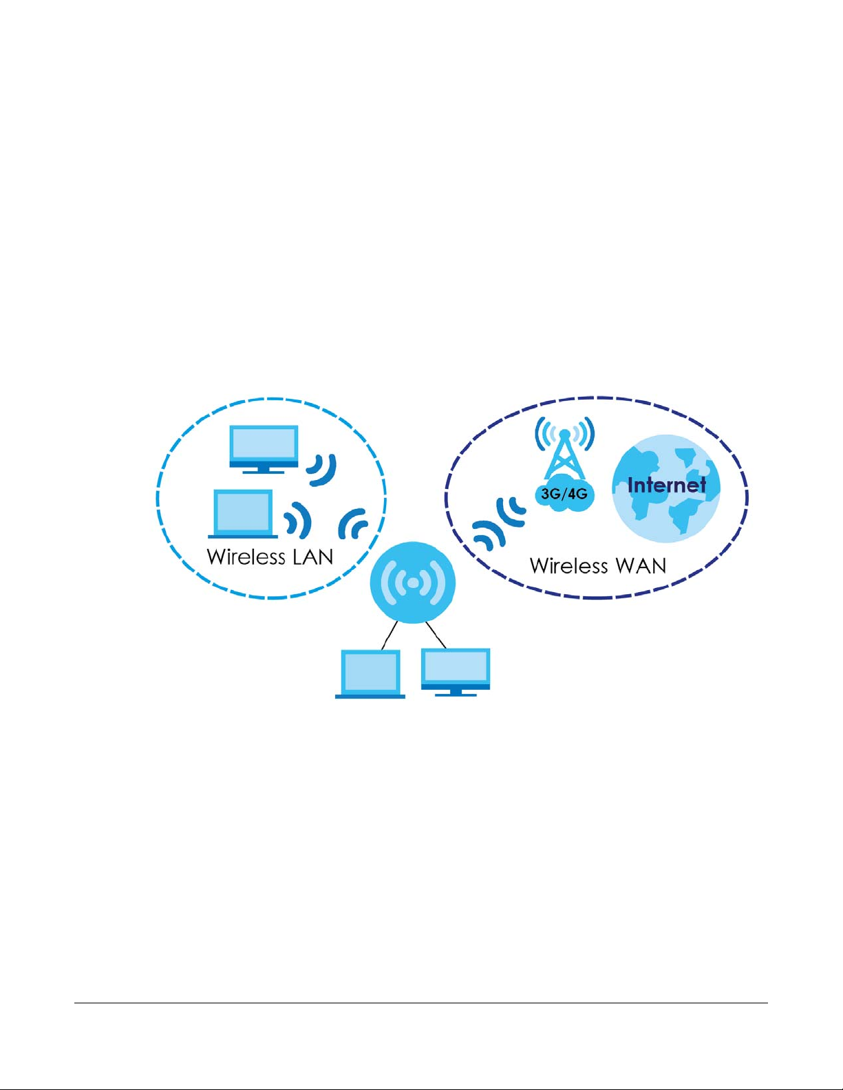
The LTE5366 is a wireless router, which can connect to a mobile network and the Internet through a
wireless WAN connection and provide easy network access to mobile users without additional wiring.
You can set up a wireless network with other IEEE 802.11a/b/g/n/ac compatible devices.
CHAPTER 1
Introduction
A range of services such as a firewall and content filtering are also available for secure Internet
computing.
1.2 Applications
Your can have the following networks with the LTE5366:
• Wired. You can connect network devices via the Ethernet ports of the LTE5366 so that they can
communicate with each other and access the Internet.
• Wireless LAN. Wireless clients can wirelessly connect to the LTE5366 to access network resources. You
can use WPS (Wi-Fi Protected Setup) to create an instant network connection with another WPScompatible device.
LTE5366 Series User’s Guide
13
Page 14
Chapter 1 Introduction
• Wireless WAN. Insert a 3G/4G SIM card into the SIM card slot to connect to a mobile network for
Internet access.
1.2.1 Wireless WAN (2G/3G/4G) Connection
The LTE5366 comes with a built-in 3G/4G module for 3G/4G connections. To set up a 3G/4G connection
using the built-in 3G/4G module, just insert a 3G/4G SIM card into the SIM card slot at the back of the
LTE5366.
Note: You must insert the 3G/4G SIM card into the card slot before turning on the LTE5366.
1.2.2 Wireless LAN (Wi-Fi) Connection
The LTE5366 is a wireless Access Point (AP) for wireless clients, such as notebook computers or PDAs and
iPads. It allows them to connect to the Internet without having to rely on inconvenient Ethernet cables.
By default, the wireless LAN (WLAN) is enabled on the LTE5366.
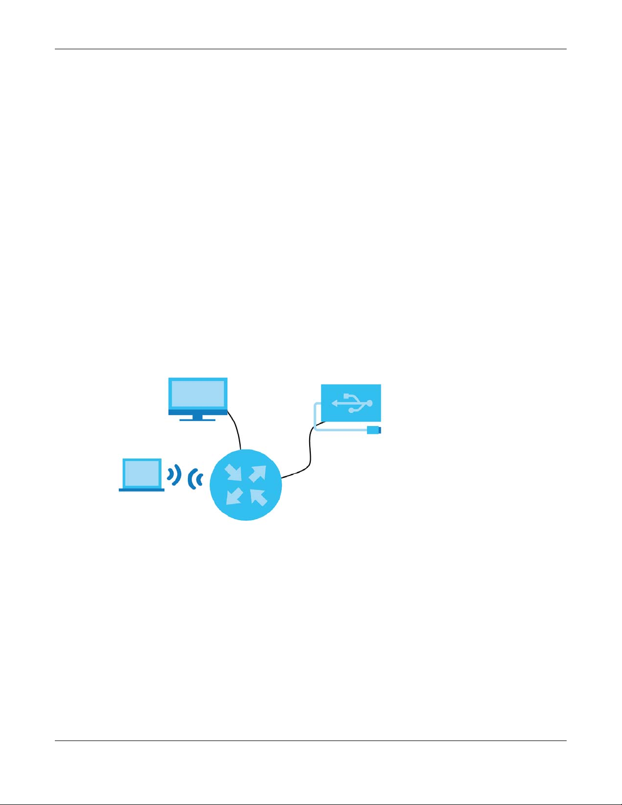
1.2.3 File Sharing
Use the built-in USB 2.0 port to share files on a USB memory stick or a USB hard drive (B). You can connect
one USB hard drive to the LTE5366 at a time. Use FTP/SAMBA to access the files on the USB device.
1.3 Ways to Manage the LTE5366
Use any of the following methods to manage the LTE5366.
• WPS (Wi-Fi Protected Setup). You can use the WPS button or the WPS section of the Web Configurator
to set up a wireless network with your LTE5366.
• Web Configurator. This is recommended for everyday management of the LTE5366 using a
(supported) web browser.
• TR-069. This is an auto-configuration server used to remotely configure your device.
LTE5366 Series User’s Guide
14
Page 15
Chapter 1 Introduction
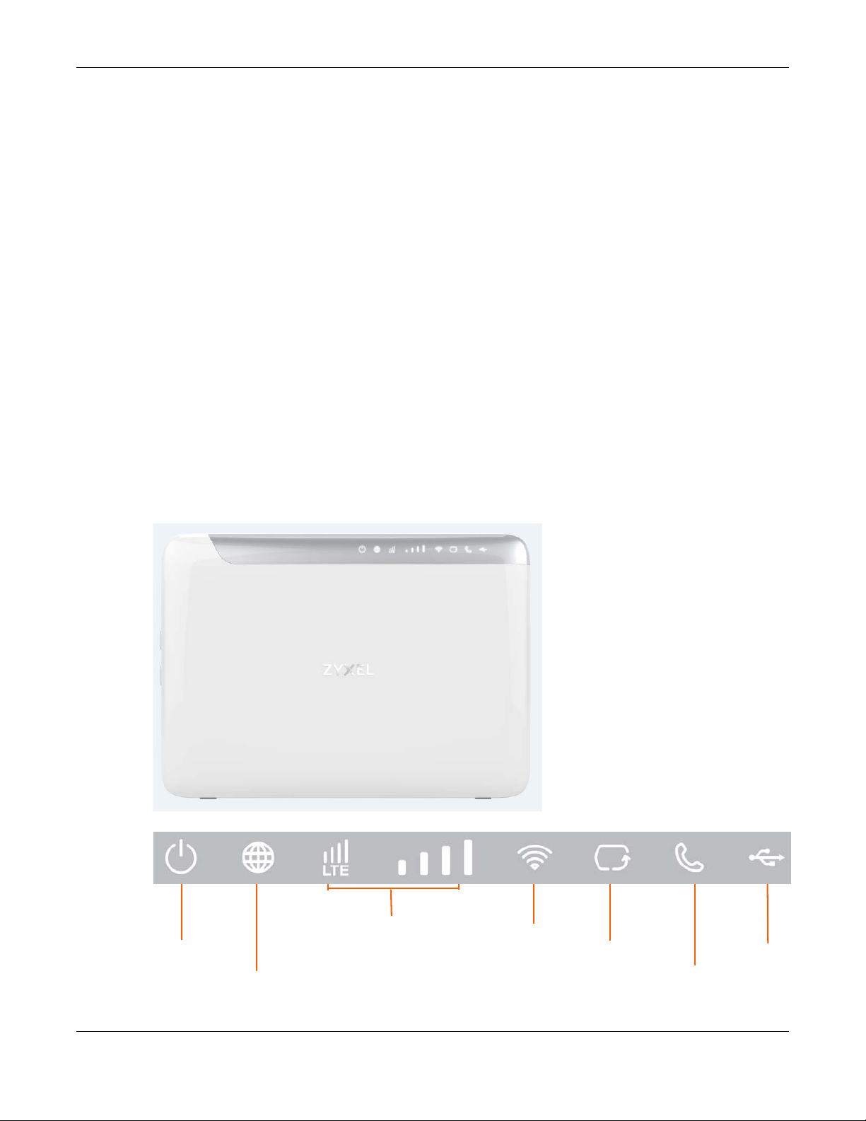
Power
Internet
WLAN/WPS
Ethernet
WAN
Phone
USB
LTE/3G/2G
Connection Status
and Signal Strength
1.4 Good Habits for Managing the LTE5366
Do the following things regularly to make the LTE5366 more secure and to manage the LTE5366 more
effectively.
• Change the password. Use a password that’s not easy to guess and that consists of different types of
characters, such as numbers and letters.
• Write down the password and put it in a safe place.
• Back up the configuration (and make sure you know how to restore it). See Section 24.8 on page 166.
Restoring an earlier working configuration may be useful if the device becomes unstable or even
crashes. If you forget your password, you will have to reset the LTE5366 to its factory default settings. If
you backed up an earlier configuration file, you would not have to totally re-configure the LTE5366.
You could simply restore your last configuration.
1.5 Hardware
1.5.1 LEDs
The following graphics display the front panel of the LTE5366.
Figure 1 Front Panel
Figure 2 LEDs
LTE5366 Series User’s Guide
15
Page 16

Chapter 1 Introduction
The following table describes the LEDs.
Table 1 Front panel LEDs
LED COLOR STATUS DESCRIPTION
Power White On The LTE5366 is receiving power and functioning properly.
Blinking The LTE5366 is in the process of starting up or default restoring.
Off The LTE5366 is not receiving power.
Internet White On The LTE5366’s WAN connection is ready.
Blinking The LTE5366 is sending/receiving data through the WAN.
Off The WAN connection is not ready, or has failed.
LTE/3G/2G White On The LTE5366 is registered and successfully connected to a 4G
Blinking
(slow)
Blinking
(fast)
Green On The LTE5366 is registered and successfully connected to a 2G/3G
Blinking
(slow)
Off There is no SIM card inserted, the SIM card is invalid, the PIN code is
Signal Strength White On A valid SIM card is inserted and the wireless WAN interface is
WLAN/WPS White On The LTE5366 is ready and the 2.4GHz wireless LAN is on, but is not
Blinking
(slow)
Blinking
(fast)
Green On The LTE5366 is ready and the 5GHz wireless LAN is on, but is not
Blinking
(slow)
Blinking
(fast)
Off The wireless LAN is not ready or has failed or WPS is disabled.
Ethernet White On The LTE5366 has an Ethernet connection.
Blinking The LTE5366 is transmitting/receiving data through the Ethernet
Off The LTE5366 does not detect an Ethernet connection.
Voice White On A telephone connected to the Voice port has its receiver on the
Blinking The LTE5366 is receiving an incoming call.
Off A telephone connected to the Voice port has its receiver off the
network.
The LTE5366 is looking for an available 4G network.
The LTE5366 is connecting to a 4G network.
network.
The LTE5366 is looking for an available 2G/3G network.
not correct or there is no service.
enabled.
• Four bars: The signal strength is Excellent.
• Three bars: The signal strength is Good.
• Two bars: The signal strength is Fair.
• One bar: The signal strength is Poor.
sending/receiving data through the wireless LAN.
The LTE5366 is connecting to a 2.4GHz WiFi-Connection via WPS.
The LTE5366 is sending/receiving data through the wireless LAN.
sending/receiving data through the wireless LAN.
The LTE5366 is connecting to a 5GHz WiFi-Connection via WPS.
The LTE5366 is sending/receiving data through the wireless LAN.
connection.
hook.
hook.
LTE5366 Series User’s Guide
16
Page 17
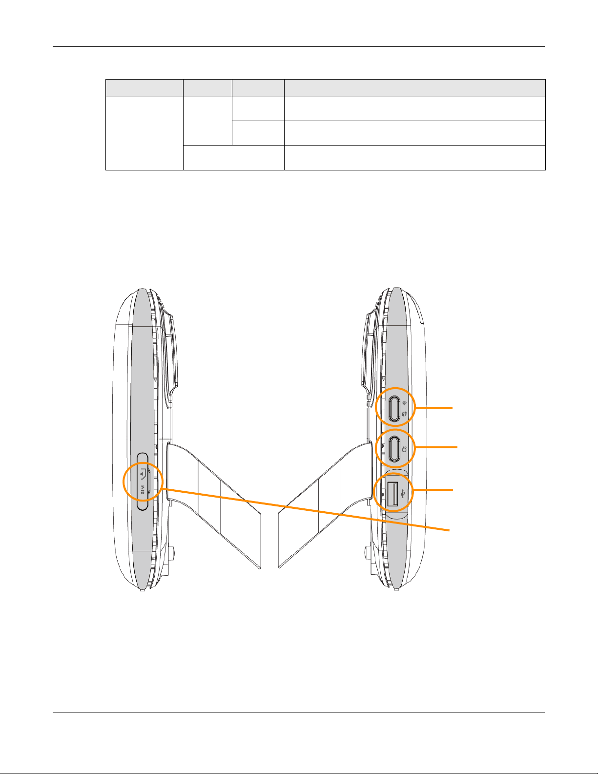
Table 1 Front panel LEDs (continued)
SIM Card
USB
WLAN/WPS
LED On/Off
LED COLOR STATUS DESCRIPTION
USB Green On The LTE5366 has a USB device installed and the interface
Note: Blinking (slow) means the LED blinks once per second. Blinking (fast) means the LED
blinks twice per second.
1.5.2 Side Panels
The following graphics display the side panels of the LTE5366.
Figure 3 Side Panels
Chapter 1 Introduction
connected is up.
Blinking The LTE5366 is sending/receiving data to/from the USB device
connected to it.
Off There is no USB device installed or the LTE5366 does not detect a
USB connection.
LTE5366 Series User’s Guide
17
Page 18

The following table describes the items on the side panels.
Table 2
LABEL DESCRIPTION
SIM Card Insert a SIM card to get a 3G/4G WAN connection.
WLAN/WPS Press this button for one second to enable/disable the wireless function.
LED On/Off Press this button less than two seconds to turn the LEDs off. Press the button for more
USB Use the built-in USB 2.0 port to share files on a USB memory stick or a USB hard drive
1.5.2.1 The WPS Button
Your LTE5366 supports Wi-Fi Protected Setup (WPS), which is an easy way to set up a secure wireless
network. WPS is an industry standard specification, defined by the Wi-Fi Alliance.
WPS allows you to quickly set up a wireless network with strong security, without having to configure
security settings manually. Each WPS connection works between two devices. Both devices must
support WPS (check each device’s documentation to make sure).
Chapter 1 Introduction
Press the WPS button for more than five seconds to quickly set up a secure wireless
connection between the device and a WPS-compatible client.
than two seconds to turn the LEDs on.
Depending on the devices you have, you can either press a button (on the device itself, or in its
configuration utility) or enter a PIN (a unique Personal Identification Number that allows one device to
authenticate the other) in each of the two devices. When WPS is activated on a device, it has two
minutes to find another device that also has WPS activated. Then, the two devices connect and set up
a secure network by themselves.
You can use the WPS button ( ) on the side panel of the LTE5366 to activate WPS in order to quickly
set up a wireless network with strong security.
1 Make sure the power LED is on (not blinking).
2 Press the WPS button for more than five seconds and release it. Press the WPS button on another WPS-
enabled device within range of the LTE5366.
Note: You must activate WPS in the LTE5366 and in another wireless device within two minutes
of each other.
For more information on using WPS, see Section 4.2 on page 34.
1.5.2.2 SIM Card Slot
The LTE5366 comes with a built-in 3G/4G module for 3G/4G connections. To set up a 3G/4G connection
using the built-in 3G/4G module, just insert a 3G/4G SIM card into the SIM card slot at the back of the
LTE5366.
Note: You must insert the SIM card into the card slot before turning on the LTE5366.
1.5.3 Rear Panel
The following graphics display the rear panel of the LTE5366.
LTE5366 Series User’s Guide
18
Page 19
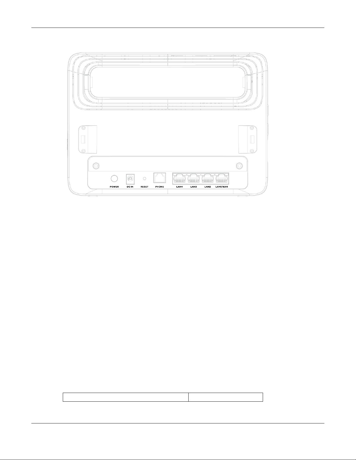
Figure 4 Rear Panel
Chapter 1 Introduction
1.6 Resetting the LTE5366
If you forget your password or IP address, or you cannot access the Web Configurator, you will need to
use the RESET button at the back of the LTE5366 to reload the factory-default configuration file. This
means that you will lose all configurations that you had previously saved, the password will be reset to
“1234” (see Section 24.4 on page 161) and the IP address will be reset to “192.168.1.1”.
1.6.1 How to Use the RESET Button
1 Make sure the power LED is on.
2 Press the RESET button for two seconds to restart/reboot the LTE5366.
3 Press the RESET button for longer than five seconds to set the LTE5366 back to its factory-default
configurations.
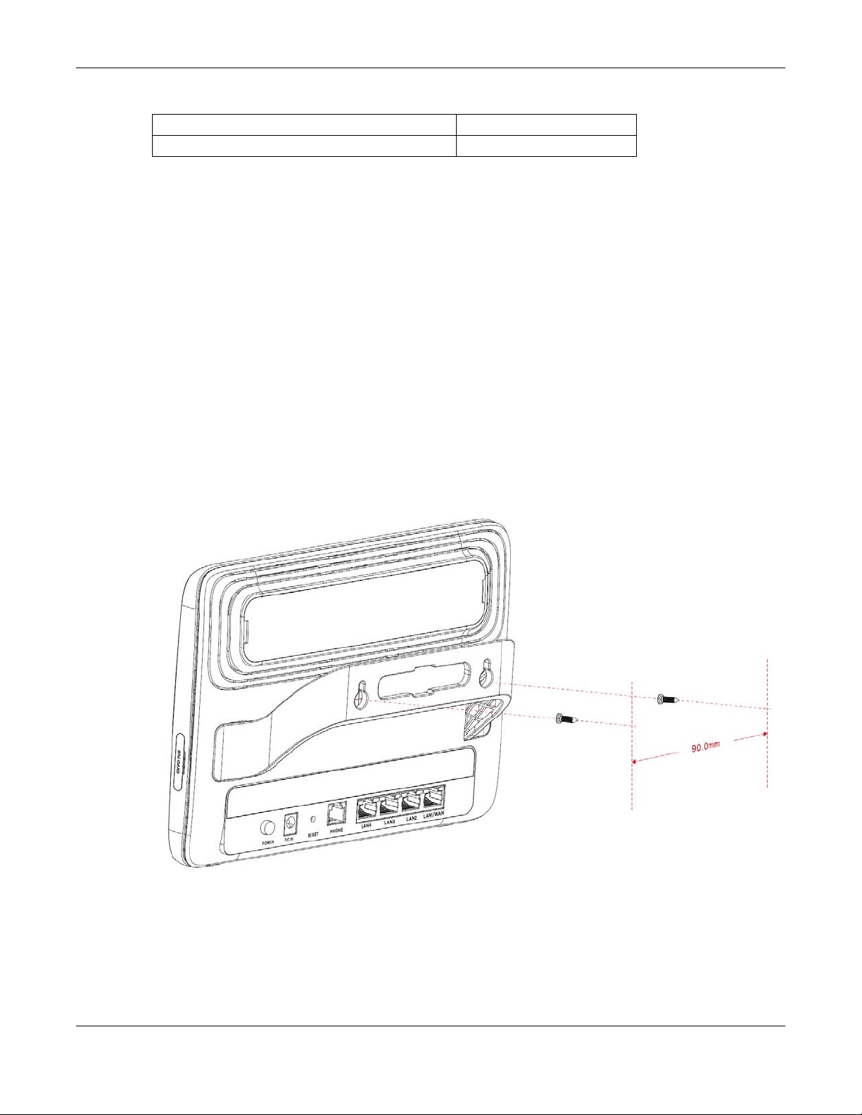
1.7 Wall Mounting
You may need screw anchors if mounting on a concrete or brick wall.
Table 3 Wall Mounting Information
Distance between holes 90mm
LTE5366 Series User’s Guide
19
Page 20
Chapter 1 Introduction
Table 3 Wall Mounting Information
M4 Screws Two
Screw anchors (optional) Two
1 Select a position free of obstructions on a wall strong enough to hold the weight of the device.
2 Mark two holes on the wall at the appropriate distance apart for the screws.
Be careful to avoid damaging pipes or cables located inside the wall
when drilling holes for the screws.
3 If using screw anchors, drill two holes for the screw anchors into the wall. Push the anchors into the full
depth of the holes, then insert the screws into the anchors. Do not insert the screws all the way in - leave
a small gap of about 0.5 cm.
If not using screw anchors, use a screwdriver to insert the screws into the wall. Do not insert the screws all
the way in - leave a gap of about 0.5 cm.
4 Make sure the screws are fastened well enough to hold the weight of the LTE5366 with the connection
cables.
5 Align the holes on the back of the LTE5366 with the screws on the wall. Hang the LTE5366 on the screws.
Figure 5 Wall Mounting Example
LTE5366 Series User’s Guide
20
Page 21

2.1 Overview
This chapter describes how to access the LTE5366 Web Configurator and provides an overview of its
screens.
The Web Configurator is an HTML-based management interface that allows easy setup and
management of the LTE5366 via Internet browser. Use Internet Explorer 9.0 and later versions, Mozilla
Firefox 21 and later versions, Safari 6.0 and later versions or Google Chrome 26.0 and later versions. The
recommended screen resolution is 1024 by 768 pixels.
In order to use the Web Configurator you need to allow:
CHAPTER 2
Introducing the Web
Configurator
• Web browser pop-up windows from your device. Web pop-up blocking is enabled by default in
Windows XP SP (Service Pack) 2.
• JavaScript (enabled by default).
• Java permissions (enabled by default).
Refer to the Troubleshooting chapter (Chapter 25 on page 169) to see how to make sure these functions
are allowed in Internet Explorer.
2.2 Accessing the Web Configurator
1 Make sure your LTE5366 hardware is properly connected and prepare your computer or computer
network to connect to the LTE5366 (refer to the Quick Start Guide).
2 Launch your web browser.
3 Type "http://192.168.1.1" as the website address.
Your computer must be in the same subnet in order to access this website address.
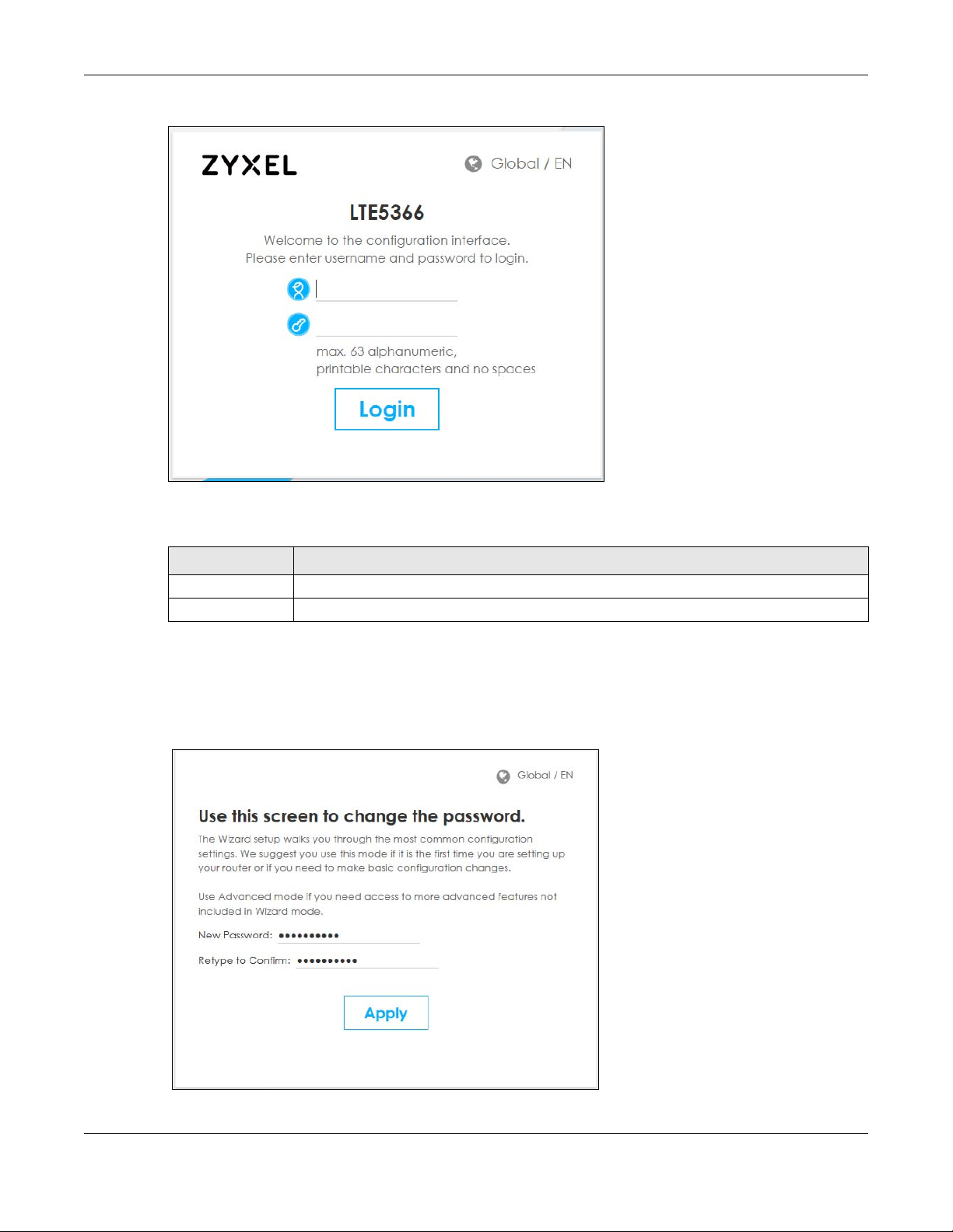
2.2.1 Login Screen
The Web Configurator initially displays the following login screen.
LTE5366 Series User’s Guide
21
Page 22
Chapter 2 Introducing the Web Configurator
Figure 6 Login screen
The following table describes the labels in this screen.
Table 4 Login screen
LABEL DESCRIPTION
User Type "admin" (default) as the user name.
Password Type "1234" (default) as the password. Click Login.
2.2.2 Password Screen
You should see a screen asking you to change your password as shown next.
Figure 7 Change Password Screen
LTE5366 Series User’s Guide
22
Page 23
Chapter 2 Introducing the Web Configurator
A
B
C
The following table describes the labels in this screen.
Table 5 Change Password Screen
LABEL DESCRIPTION
New Password Type a new password.
Retype to Confirm Retype the password for confirmation.
Apply Click Apply to save your changes back to the LTE5366.
Note: The management session automatically times out when the time period set in the
Administrator Inactivity Timer field expires (default five minutes; go to Chapter 24 on
page 160 to change this). Simply log back into the LTE5366 if this happens.
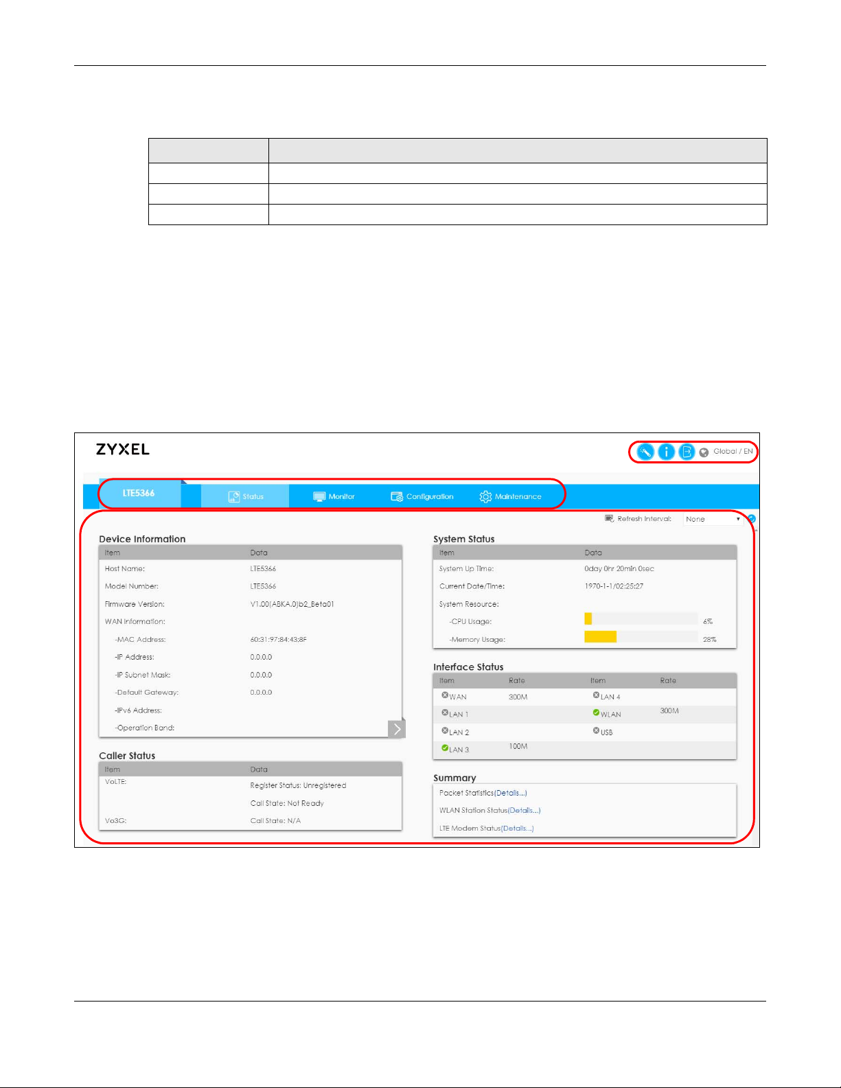
2.3 The Main Screen
The Web Configurator’s main screen is divided into these parts:
Figure 8 The Web Configurator’s Main Screen
• A - Title Bar
• B - Navigation Panel
• C - Main Window
LTE5366 Series User’s Guide
23
Page 24
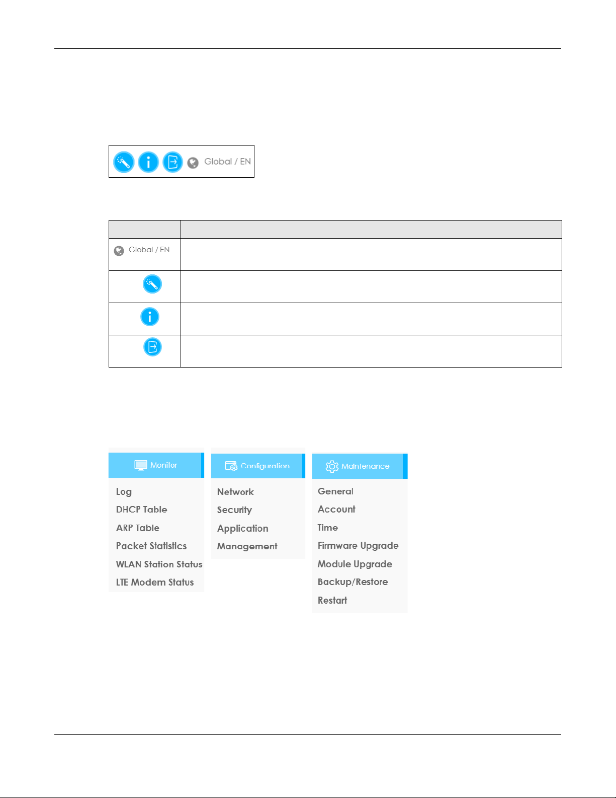
2.3.1 Title Bar
The title bar provides some useful links that always appear over the screens below, regardless of how
deep into the Web Configurator you navigate.
Figure 9 Title Bar
The icons provide the following functions.
Table 6 Title Bar: Web Configurator Icons
LABEL DESCRIPTION
Wizard Click this icon to open the setup wizard for the LTE5366.
About Click this icon to open a screen where you can click a link to visit the ZyXEL web site to see
Chapter 2 Introducing the Web Configurator
Select the language you prefer.
detailed product information.
Logout Click this icon to log out of the Web Configurator.
2.3.2 Navigation Panel
Use the sub-menus on the navigation panel to configure LTE5366 features.
Figure 10 Navigation Panel
LTE5366 Series User’s Guide
24
Page 25

Chapter 2 Introducing the Web Configurator
The following table describes the sub-menus.
Table 7 Navigation Panel
LINK TAB FUNCTION
Status This screen shows the LTE5366’s general device, system and interface status
Monitor
Log View Log Use this screen to view the list of activities recorded by your LTE5366.
Log Setting Use this screen to configure which logs to display.
DHCP Table DHCP Table Use this screen to view current DHCP client information.
ARP Table ARP Table Use this screen to view the ARP table. It displays the IP and MAC address of
Packet Statistics Packet
Statistics
WLAN Station
Status
LTE Modem
Status
Configuration
Network
WAN Management
Wireless LAN General Use this screen to enable the wireless LAN and configure wireless LAN and
LAN IP Use this screen to configure LAN IP address and subnet mask.
DHCP Server General Use this screen to enable the LTE5366’s DHCP server.
Association
List
LTE Modem
Status
WAN
Network Scan Use this screen to specify the type of the mobile network to which the LTE5366
IPv6 Use this screen to configure the LTE5366’s IPv6 settings.
PIN
Management
More AP Use this screen to configure multiple BSSs on the LTE5366.
MAC Filter Use the MAC filter screen to allow or deny wireless stations based on their MAC
Advanced This screen allows you to configure advanced wireless LAN settings.
QoS Use this screen to configure Wi-Fi Multimedia Quality of Service (WMM QoS).
WPS Use this screen to configure the WPS settings.
WPS Station Use this screen to add a wireless station using WPS.
Scheduling Use this screen to schedule the times the Wireless LAN is enabled.
WDS Use this screen to enable and configure the WDS settings.
Advanced Use this screen to assign IP addresses to specific individual computers based
Client List Use this screen to view information related to your DHCP status.
information. Use this screen to access the summary statistics tables.
each DHCP connection.
Use this screen to view port status and packet specific statistics.
Use this screen to view the wireless stations that are currently associated to the
LTE5366’s 2.4GHz wireless LAN.
Use this screen to view the detailed information about the LTE module, cellular
interface, and SIM card. You can also view the LTE connection status.
This screen allows you to configure ISP parameters, WAN IP address
assignment, and DNS servers.
is connected and how you want the LTE5366 to connect to an available
mobile network.
Use this screen to enable PIN code authentication and enter the PIN code.
wireless security settings.
addresses from connecting to the LTE5366.
WMM QoS allows you to prioritize wireless traffic according to the delivery
requirements of individual services.
on their MAC addresses and to have DNS servers assigned by the DHCP server.
LTE5366 Series User’s Guide
25
Page 26

Chapter 2 Introducing the Web Configurator
Table 7 Navigation Panel (continued)
LINK TAB FUNCTION
NAT General Use this screen to enable NAT.
Port
Forwarding
Port Trigger Use this screen to change your LTE5366’s port triggering settings.
ALG Use this screen to enable or disable SIP (VoIP) ALG (Application Layer
Dynamic DNS Dynamic DNS Use this screen to set up dynamic DNS.
Routing Static Route Use this screen to configure IP static routes.
Dynamic
Routing
Interface
Group
Security
Firewall General Use this screen to activate/deactivate the firewall.
Content Filter Content Filter Use this screen to restrict web features and designate a trusted computer. You
IPv6 firewall Services Use this screen to configure IPv6 firewall rules.
Application
SMS SMS Use this screen to send new messages and view messages received on the
Voice over 3GGeneral Use this screen to enable Vo3G on the LTE5366.
NAS File Sharing Use this screen to allow file sharing via the LTE5366 using Windows Explorer, the
Management
Remote
Management
Bandwidth
Management
UPnP UPnP Use this screen to enable UPnP on the LTE5366.
TR069 TR069 Use this screen to configure your LTE5366 to be managed by an ACS.
Maintenance
General General Use this screen to view and change administrative settings such as system and
Account User Account Use this screen to change the user name and password of your LTE5366.
Time Time Setting Use this screen to change your LTE5366’s time and date.
Interface
Group
Services This screen shows a summary of the firewall rules, and allows you to edit/add a
Phone Book Use this screen to manage your Vo3G contact names and phone numbers.
Telephone
Conf.
Call Conf. Use this screen to maintain rules for handling incoming calls.
FTP Use this screen to allow file sharing via the LTE5366 using FTP.
WWW Use this screen to specify from which zones you can access the LTE5366 using
Remote
Management
General Use this screen to enable bandwidth management.
Advanced Use this screen to set the upstream bandwidth and edit a bandwidth
Use this screen to configure servers behind the LTE5366 and forward incoming
service requests to the server(s) on your local network.
Gateway) in the LTE5366.
Use this screen to enable and configure RIP on the LTE5366.
Use this screen to create a new interface group.
firewall rule.
can also block certain web sites containing certain keywords in the URL.
LTE5366.
Use this screen to configure call features.
workgroup name.
HTTP or HTTPS.
Use this screen to enable specific traffic directions for network services.
management rule.
domain names.
LTE5366 Series User’s Guide
26
Page 27
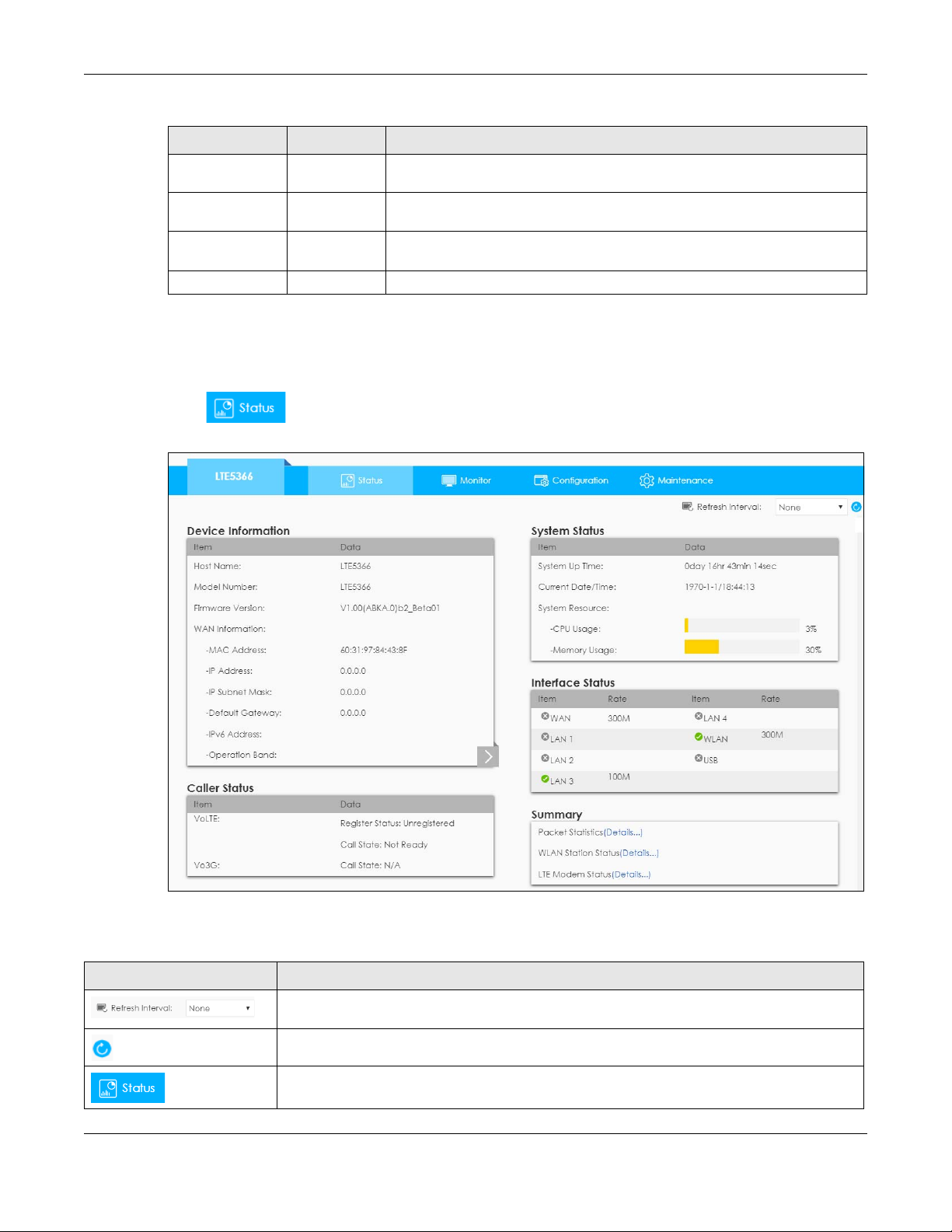
Table 7 Navigation Panel (continued)
LINK TAB FUNCTION
Firmware
Upgrade
Module
Upgrade
Backup/
Restore
Restart System Restart This screen allows you to reboot the LTE5366 without turning the power off.
Firmware
Upgrade
Module
Upgrade
Backup/
Restore
2.4 Status Screen
Click to open the status screen.
Figure 11 Status Screen
Chapter 2 Introducing the Web Configurator
Use this screen to upload firmware to your LTE5366.
Use this screen to upload firmware for the built-in LTE module.
Use this screen to backup and restore the configuration or reset the factory
defaults to your LTE5366.
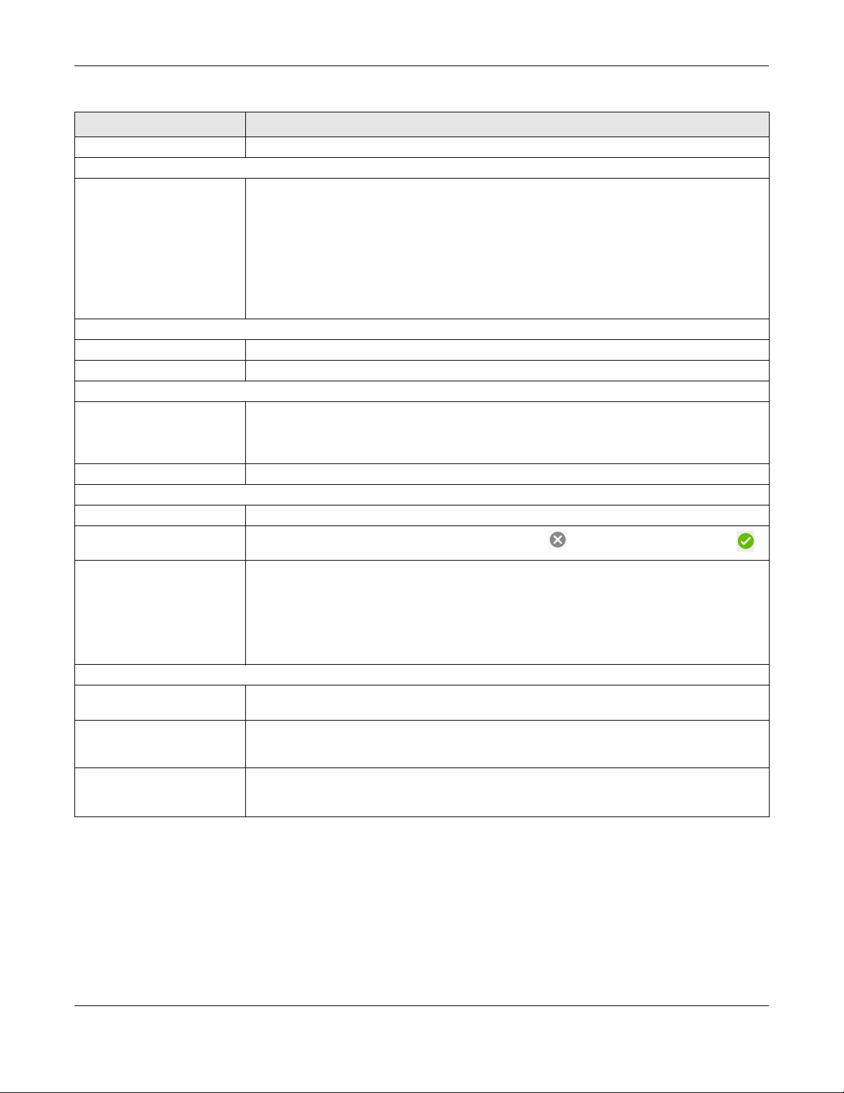
The following table describes the icons shown in the Status screen.
Table 8 Status Screen Icon Key
ICON DESCRIPTION
Select a number of seconds or None from the drop-down list box to refresh all screen statistics
automatically at the end of every time interval or to not refresh the screen statistics.
Click this button to refresh the status screen statistics.
Click this icon to see the Status page. The information in this screen depends on the device
mode you select.
LTE5366 Series User’s Guide
27
Page 28
Chapter 2 Introducing the Web Configurator
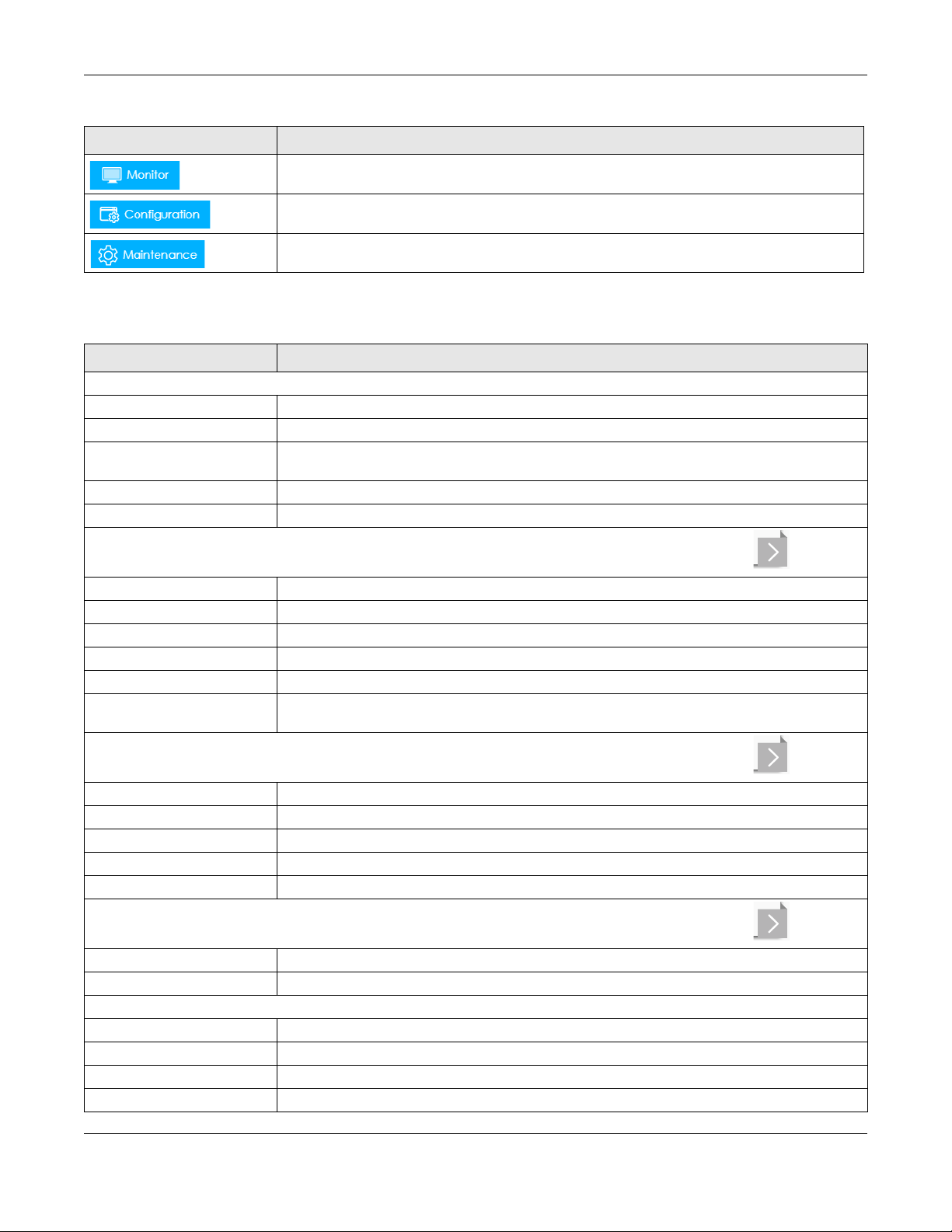
Table 8 Status Screen Icon Key (continued)
ICON DESCRIPTION
Click this icon to see the Monitor navigation menu.
Click this icon to see the Configuration navigation menu.
Click this icon to see the Maintenance navigation menu.
The following table describes the labels shown in the Status screen.
Table 9 Status Screen
LABEL DESCRIPTION
Device Information
Item This column shows the type of data the LTE5366 is recording.
Data This column shows the actual data recorded by the LTE5366.
Host Name This is the System Name you enter in the Maintenance > General screen. It is for identification
purposes.
Model Number This is the model name of your device.
Firmware Version This is the firmware version and the date created.
WAN Information
To change from WAN information to LAN information or WLAN information and vice versa click the gray arrow .
MAC Address This shows the WAN Ethernet adapter MAC Address of your device.
IP Address This shows the WAN port’s IP address.
IP Subnet Mask This shows the WAN port’s subnet mask.
Default Gateway This shows the WAN port’s gateway IP address.
IPv6 Address This shows the IPv6 address of the LTE5366 on the WAN.
Operation Band This shows the network type and the frequency band used by the mobile network to which the
LTE5366 is connecting.
LAN Information
To change from LAN information to WLAN information or WAN information and vice versa click the gray arrow .
MAC Address This shows the LAN Ethernet adapter MAC Address of your device.
IP Address This shows the LAN port’s IP address.
IP Subnet Mask This shows the LAN port’s subnet mask.
DHCP This shows the LAN port’s DHCP role - Server or Disable.
IPv6 Address This shows the IPv6 address of the LTE5366 on the LAN.
WLAN Information
To change from WLAN information to WAN information or LAN information and vice versa click the gray arrow .
WLAN OP Mode This is the device mode to which the LTE5366’s wireless LAN is set - Access Point Mode.
MAC Address This shows the 2.4GHz wireless adapter MAC Address of your device.
2.4G / 5G
SSID This shows a descriptive name used to identify the LTE5366 in the 2.4G/5GHz wireless LAN.
Channel This shows the channel number which you select manually.
System This shows the wireless standards the LTE5366 supports.
Security This shows the level of wireless security the LTE5366 is using.
LTE5366 Series User’s Guide
28
Page 29
Chapter 2 Introducing the Web Configurator
Table 9 Status Screen (continued)
LABEL DESCRIPTION
Firewall This shows whether the firewall is enabled or not.
Caller Status
Vo3G This shows the current state of the phone call.
• ready: Voice over 3G (Vo3G) is enabled and the 3G connection is up.
• not ready: Voice over 3G (Vo3G) is disabled and the 3G connection is down.
• busy: There is a Vo3G call in progress or the callee’s line is busy.
• ringing: The phone is ringing for an incoming Vo3G call.
• dialing: The callee’s phone is ringing.
• off hook: The callee hung up or your phone was left off the hook.
N/A means Voice over 3G (Vo3G) is disabled.
System Status
System Up Time This is the total time the LTE5366 has been on.
Current Date/Time This field displays your LTE5366’s present date and time.
System Resource
- CPU Usage This displays what percentage of the LTE5366’s processing ability is currently used. When this
percentage is close to 100%, the LTE5366 is running at full load, and the throughput is not going to
improve anymore. If you want some applications to have more throughput, you should turn off
other applications (for example, using bandwidth management.)
- Memory Usage This shows what percentage of the heap memory the LTE5366 is using.
Interface Status
Item This displays the LTE5366 port types. The port types are: WAN, LAN and WLAN.
Status For the LAN, WAN and USB ports, this field displays an X (when the line is down) or Tick
Rate For the LAN ports, this displays the port speed or is left blank when the line is disconnected.
(when the line is up or connected).
For the WAN port, it always displays the maximum transmission rate.
For the 2.4GHz WLAN, it displays the maximum transmission rate when the WLAN is enabled and is
left blank when the WLAN is disabled.
For the USB port, it displays the port speed or is left blank when the line is disconnected.
Summary
Packet Statistics Click Details... to go to the Monitor > Packet Statistics screen (Section 5.6 on page 49). Use this
screen to view port status and packet specific statistics.
WLAN Station Status Click Details... to go to the Monitor > WLAN Station Status screen (Section 5.7 on page 50). Use
LTE Modem Status Click Details... to go to the Monitor > LTE Modem Status screen (Section 5.8 on page 51). Use this
this screen to view the wireless stations that are currently associated to the LTE5366’s 2.4GHz
wireless LAN.
screen to view the detailed information about the LTE module, cellular interface, and SIM card.
You can also view the LTE connection status.
LTE5366 Series User’s Guide
29
Page 30

3.1 Overview
This chapter provides information on the wizard setup screens in the Web Configurator.
The Web Configurator’s wizard helps you configure your device to access the Internet and change the
wireless LAN settings. Refer to your ISP for your Internet account information. Leave a field blank if you
don’t have that information.
3.2 Accessing the Wizard
1 Launch your web browser and type "http://192.168.1.1" as the website address. Type "admin" (default)
as the user name, "1234" (default) as the password and click Login.
CHAPTER 3
Setup Wizard
2 Click the Wizard icon in the top right corner of the web configurator to open the Wizard screen.
Figure 12 Title Bar: Wizard icon
3.3 Wizard Setup
1 The first wizard screen displays showing the main steps in the wizard setup. Click Next to proceed to the
time zone setup screen.
LTE5366 Series User’s Guide
30
Page 31

Chapter 3 Setup Wizard
Figure 13 Wizard: Start
2 The LTE5366 automatically detects your location and displays the correct time zone. If the result is not
correct, click Detect Again or manually select the time zone of the LTE5366’s location and click Next.
Figure 14 Wizard: Time
3 Enter your APN (Access Point Name) provided by your service provider. Select the country where the
LTE5366 is located and your service provider name. Click Next.
Figure 15 Wizard: WAN
LTE5366 Series User’s Guide
31
Page 32

Chapter 3 Setup Wizard
4 Use this screen to enable or disable the LTE5366’s wireless LAN, and enter the wireless network name
(SSID). Select a channel or use Auto to have the LTE5366 automatically determine a channel to use.
Click Next.
Figure 16 Wizard: Wireless Settings
5 Select WPA2-PSK and enter a pre-shared key from 8 to 63 case-sensitive characters for data encryption.
The wireless clients which want to associate with this wireless network must have the same wireless
security settings. Otherwise, select No Security to allow any client to associate with this network without
any data encryption or authentication. Click Next.
Figure 17 Wizard: Wireless Security
6 Use the read-only summary table to check whether what you have configured is correct. Click Apply
Settings to save your settings. Otherwise, click Back to go back to the previous screens.
LTE5366 Series User’s Guide
32
Page 33

Chapter 3 Setup Wizard
Figure 18 Wizard: Summary
7 Wait while the system applies settings.
Figure 19 Wizard: Apply Settings
8 Click Finish to complete the wizard setup.
Figure 20 Wizard: Finish
You are now ready to connect wirelessly to your LTE5366 and access the Internet.
LTE5366 Series User’s Guide
33
Page 34

CHAPTER 4
4.1 Overview
This chapter provides tutorials for setting up your LTE5366.
• Set Up a Wireless Network Using WPS
• Connect to LTE5366 Wireless Network without WPS
• Using Multiple SSIDs on the LTE5366
4.2 Set Up a Wireless Network Using WPS
This section gives you an example of how to set up wireless network using WPS. This example uses the
LTE5366 as the AP and NWD210N as the wireless client which connects to a notebook.
Tutorials
Note: The wireless client must be a WPS-aware device (for example, a WPS USB adapter or
PCI card).
There are two WPS methods for creating a secure connection via the web configurator or utility. This
tutorial shows you how to do both.
• Push Button Configuration (PBC) - create a secure wireless network simply by pressing a button. See
Section 4.2.1 on page 34. This is the easier method.
• PIN Configuration - create a secure wireless network simply by entering a wireless client's PIN (Personal
Identification Number) in the LTE5366’s interface. See Section 4.2.2 on page 35. This is the more secure
method, since one device can authenticate the other.
4.2.1 Push Button Configuration (PBC)
1 Make sure that your LTE5366 is turned on. Make sure the WIFI button (at the side panel of the LTE5366) is
pushed in, and that the device is placed within range of your notebook.
2 Make sure that you have installed the wireless client (this example uses the NWD210N) driver and utility in
your notebook.
3 In the wireless client utility, find the WPS settings. Enable WPS and press the WPS button (Start or WPS
button).
4 Log into LTE5366’s Web Configurator and press the Push Button in the Configuration > Network > Wireless
LAN > WPS Station screen.
LTE5366 Series User’s Guide
34
Page 35
Chapter 4 Tutorials
Wireless Client
SECURITY INFO
COMMUNICATION
WITHIN 2 MINUTES
AP
Press and hold
for more than
1 second
Note: Your LTE5366 has a WPS button located on its panel, as well as a WPS button in its
configuration utility. Both buttons have exactly the same function; you can use one or
the other.
Note: It doesn’t matter which button is pressed first. You must press the second button within
two minutes of pressing the first one.
The LTE5366 sends the proper configuration settings to the wireless client. This may take up to two
minutes. Then the wireless client is able to communicate with the LTE5366 securely.
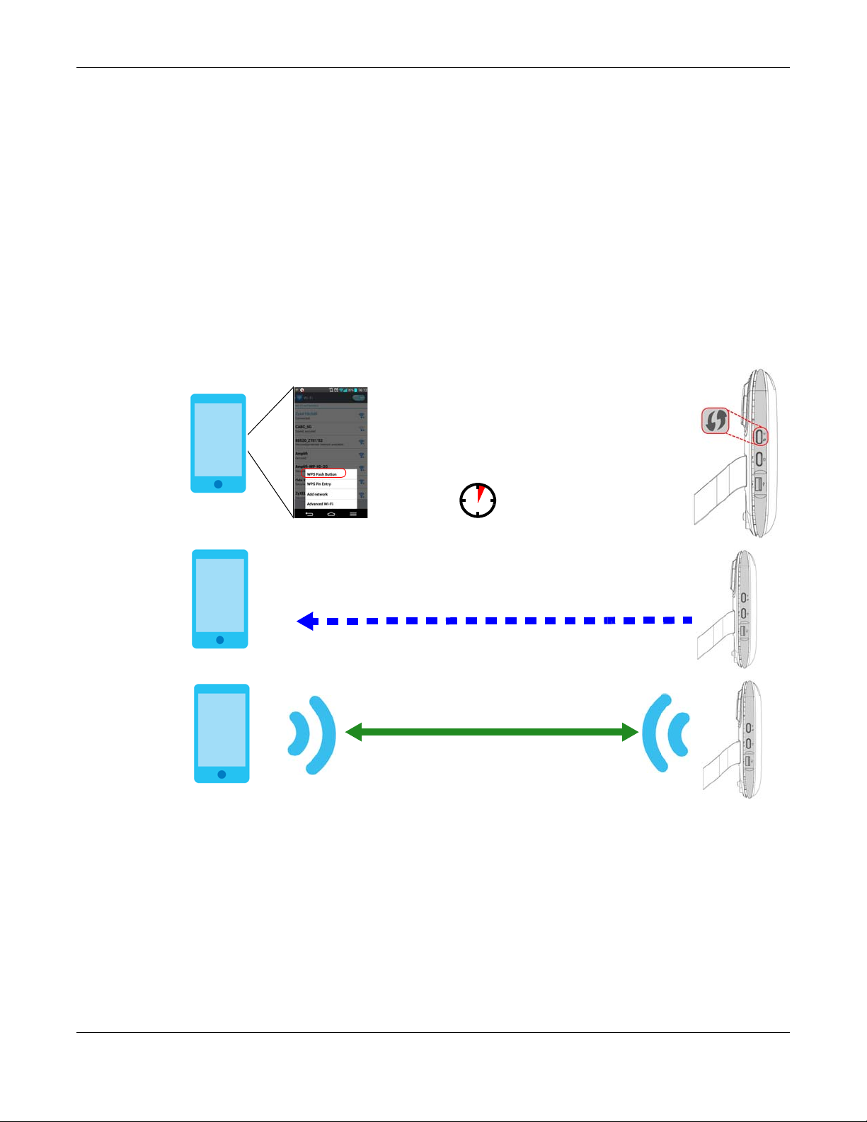
The following figure shows you an example of how to set up a wireless network and its security by
pressing a button on both LTE5366 and wireless client (the Android 4.4.2 phone in this example).
Figure 21 Example WPS Process: PBC Method
4.2.2 PIN Configuration
1 Launch your wireless client’s configuration utility. Go to the WPS settings and select the PIN method to
2 Enter the PIN number to the PIN field in the Configuration > Network > Wireless LAN > WPS Station screen
When you use the PIN configuration method, you need to use both LTE5366’s configuration interface
and the client’s utilities.
get a PIN number.
on the LTE5366.
LTE5366 Series User’s Guide
35
Page 36
Chapter 4 Tutorials
SECURITY INFO
WITHIN 2 MINUTES
Enter WPS PIN
WPS
from other device:
WPS
START
Wireless Client
AP
Authentication by PIN
COMMUNICATION
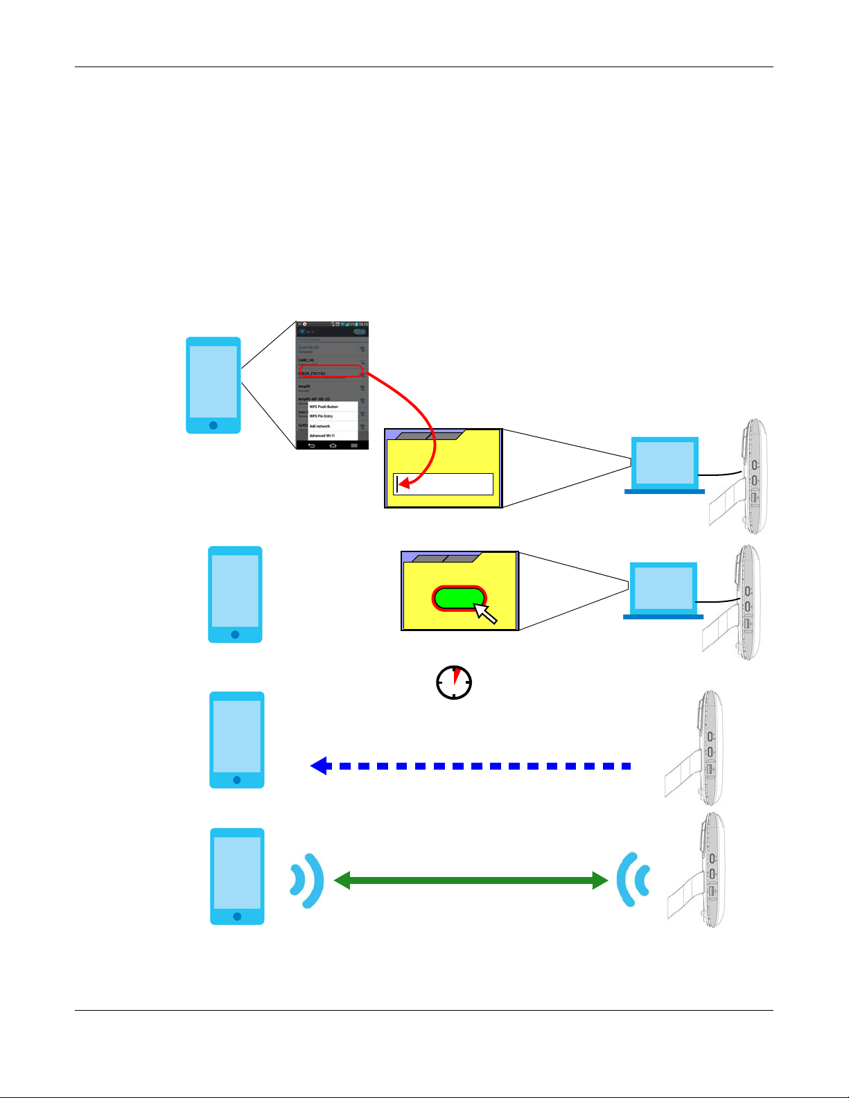
3 Click Start buttons (or button next to the PIN field) on both the wireless client utility screen and the
LTE5366’s WPS Station screen within two minutes.
The LTE5366 authenticates the wireless client and sends the proper configuration settings to the wireless
client. This may take up to two minutes. Then the wireless client is able to communicate with the LTE5366
securely.
The following figure shows you how to set up a wireless network and its security on a LTE5366 and a
wireless client (android 4.4.2 smartphone) by using PIN method.
Figure 22 Example WPS Process: PIN Method
LTE5366 Series User’s Guide
36
Page 37
Chapter 4 Tutorials
4.3 Connect to LTE5366 Wireless Network without WPS
This example shows you how to configure wireless security settings with the following parameters on your
LTE5366 and connect your computer to the LTE5366 wireless network.
SSID SSID_Example3
Channel 6
Security WPA-PSK
(Pre-Shared Key: 1234567890)
Follow the steps below to configure the wireless settings on your LTE5366.
The instructions require that your hardware is connected (see the Quick Start Guide) and you are
logged into the Web Configurator through your LAN connection (see Section 2.2 on page 21).
1 Make sure the WIFI switch (at the back panel of the LTE5366) is set to ON.
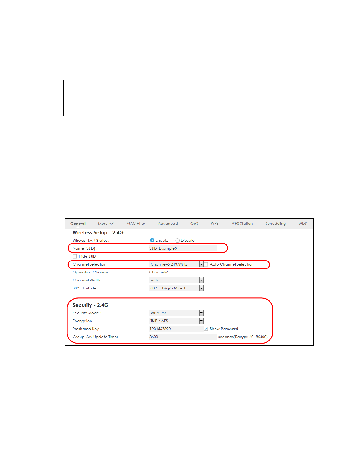
2 Open the Configuration > Network > Wireless LAN > General screen in the AP’s Web Configurator.
3 Confirm that the wireless LAN is enabled on the LTE5366.
4 Enter SSID_Example3 as the SSID and select Channel-06 as the channel. Set security mode to WPA2-PSK
and enter 1234567890 in the Pre-Shared Key field. Click Apply.
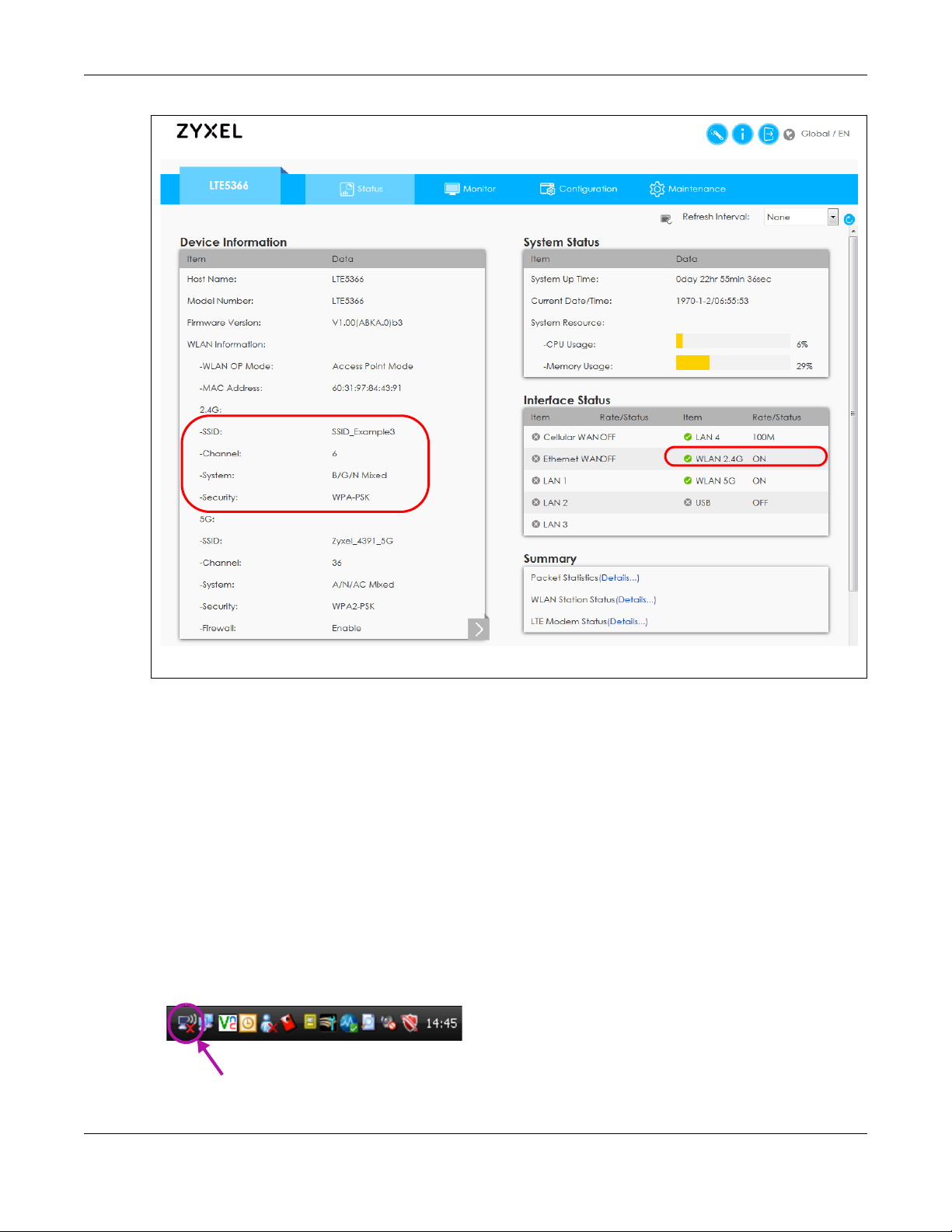
5 Open the Status screen. Verify your wireless and wireless security settings under Device Information and
check if the WLAN connection is up under Interface Status.
LTE5366 Series User’s Guide
37
Page 38
Chapter 4 Tutorials
4.3.1 Configure Your Notebook
Note: In this example, we use the ZyXEL NWD6505 wireless adapter as the wireless client and
use the Windows built-in utility (Windows Zero Configuration (WZC)) to connect to the
wireless network.
1 The LTE5366 supports IEEE 802.11b, IEEE 802.11g, and IEEE 802.11n wireless clients. Make sure that your
notebook or computer’s wireless adapter supports one of these standards.
2 Wireless adapters come with software sometimes called a “utility” that you install on your computer. See
your wireless adapter’s User’s Guide for information on how to do that.
3 After you’ve installed the driver and attached the NWD6505 to your computer’s USB port, right-click the
Wireless Network Connection icon in your computer’s system tray, select and click View Available
Wireless Networks.
LTE5366 Series User’s Guide
38
Page 39

Chapter 4 Tutorials
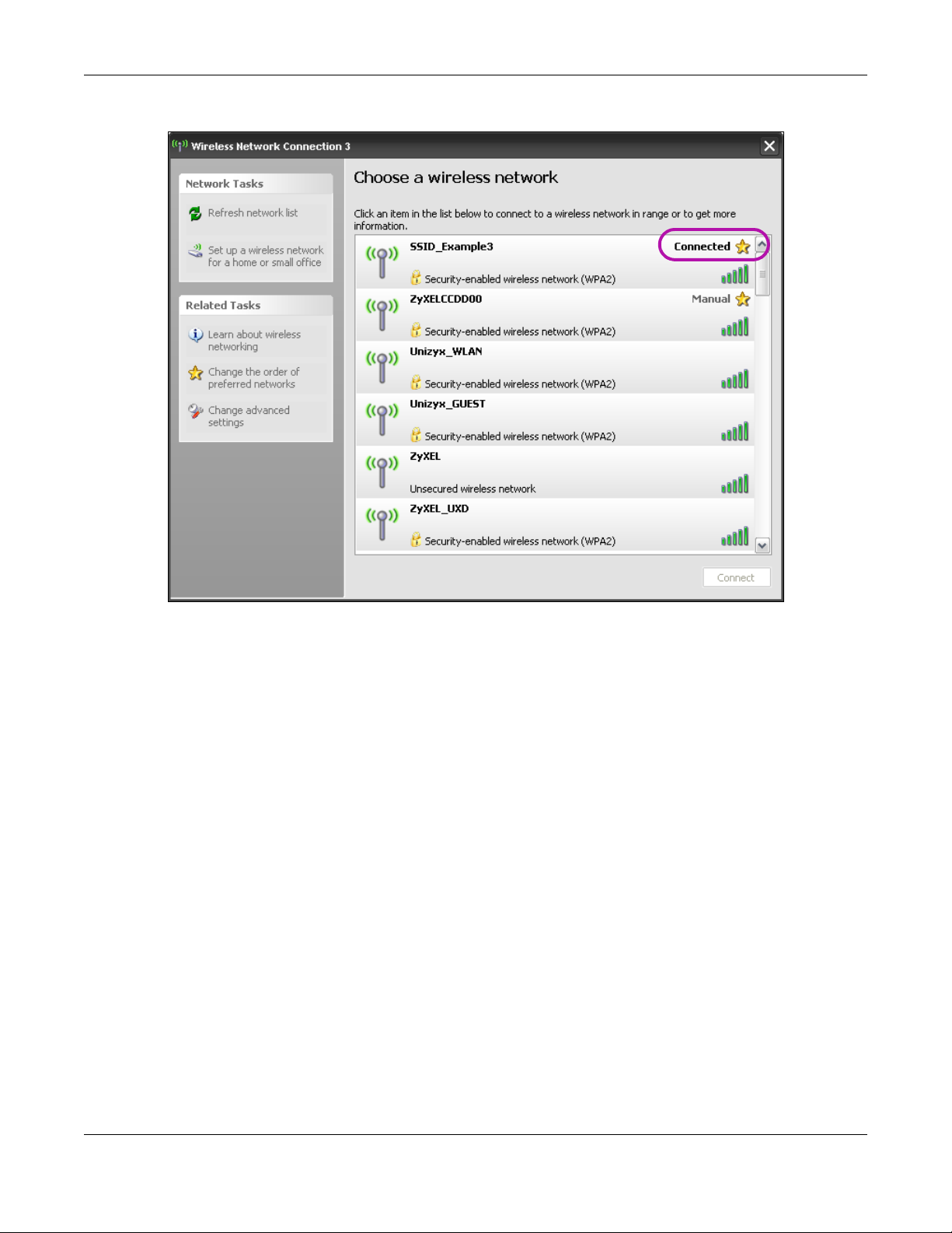
4 The Wireless Network Connection screen displays. Click Refresh network list to view the available wireless
APs within range.
5 Select SSID_Example3 and click Connect.
6 Type the security key in the following screen. Click Connect.
LTE5366 Series User’s Guide
39
Page 40
Chapter 4 Tutorials
7 Check the status of your wireless connection in the screen below.
8 If the wireless client keeps trying to connect to or acquiring an IP address from the LTE5366, make sure
you entered the correct security key.
If the connection has limited or no connectivity, make sure the DHCP server is enabled on the LTE5366.
If your connection is successful, open your Internet browser and enter http://www.zyxel.com or the URL
of any other web site in the address bar. If you are able to access the web site, your wireless connection
is successfully configured.
4.4 Using Multiple SSIDs on the LTE5366
You can configure more than one SSID on a LTE5366. See Section 7.4 on page 76.
This allows you to configure multiple independent wireless networks on the LTE5366 as if there were
multiple APs (virtual APs). Each virtual AP has its own SSID, and wireless security type. That is, each SSID on
the LTE5366 represents a different access point/wireless network to wireless clients in the network.
Clients can associate only with the SSIDs for which they have the correct security settings. Clients using
different SSIDs can access the Internet and the wired network behind the LTE5366 (such as a printer).
LTE5366 Series User’s Guide
40
Page 41

Chapter 4 Tutorials
For example, you may set up three wireless networks (A, B and C) in your office. A is for workers, B is for
guests and C is specific to a VoIP device in the meeting room.
4.4.1 Configuring Security Settings of Multiple SSIDs
The LTE5366 is in router mode by default.
This example shows you how to configure the SSIDs with the following parameters on your LTE5366 .
SSID SECURITY TYPE KEY
Zyxel_Worker WPA2-PSK
WPA Compatible
Zyxel_VoIP WPA-PSK VoIPOnly12345678
Zyxel_Guest WPA-PSK keyexample123
1 Connect your computer to the LAN port of the LTE5366 using an Ethernet cable.
2 The default IP address of the LTE5366is “192.168.1.1”. In this case, your computer must have an IP address
in the range between “192.168.1.2” and “192.168.1.254”.
3 Click Start > Run on your computer in Windows. Type “cmd” in the dialog box. Enter “ipconfig” to show
your computer’s IP address. If your computer’s IP address is not in the correct range then see Appendix
C on page 189 for information on changing your computer’s IP address.
4 After you’ve set your computer’s IP address, open a web browser such as Internet Explorer and type
“http://192.168.1.1” as the web address in your web browser.
DoNotStealMyWirelessNetwork
5 Enter “admin” as the user name and “1234” (default) as the password and click Login.
6 Type a new password and retype it to confirm, then click Apply. Otherwise, click Ignore.
7 Go to Configuration > Network > Wireless LAN > More AP. Click the Edit icon of the first entry to configure
wireless and security settings for SSID_Worker.
LTE5366 Series User’s Guide
41
Page 42

Chapter 4 Tutorials
8 Configure the screen as follows. In this example, you enable Intra-BSS Traffic for SSID_Worker to allow
wireless clients in the same wireless network to communicate with each other. Click Apply.
9 Click the Edit icon of the second entry to configure wireless and security settings for SSID_VoIP.
10 Configure the screen as follows. You do not enable Intra-BSS Traffic for SSID_VoIP. Click Apply.
LTE5366 Series User’s Guide
42
Page 43

Chapter 4 Tutorials
11 Click the Edit icon of the third entry to configure wireless and security settings for SSID_Guest.
12 Configure the screen as follows. In this example, you enable Intra-BSS Traffic for SSID_Guest to allow
wireless clients in the same wireless network to communicate with each other. Click Apply.
LTE5366 Series User’s Guide
43
Page 44

Chapter 4 Tutorials
LTE5366 Series User’s Guide
44
Page 45

PART II
Technical Reference
45
Page 46

5.1 Overview
This chapter discusses read-only information related to the device state of the LTE5366.
To access the Monitor screens, click after login.
You can also click the links in the Summary table of the Status screen to view the packets sent/received
as well as the status of wireless clients connected to the LTE5366.
5.2 What You Can Do
• Use the Log screen to see the logs for the activity on the LTE5366 (Section 5.3 on page 46).
• Use the DHCP Table screen to view information related to your DHCP status (Section 5.4 on page 48).
• Use the ARP Table screen to the ARP table to view IP-to-MAC address mapping(s) (Section 5.5 on
page 48).
•use the Packet Statistics screen to view port status, packet specific statistics, the "system up time" and
so on (Section 5.6 on page 49).
• Use the WLAN Station Status screen to view the wireless stations that are currently associated to the
LTE5366 (Section 5.7 on page 50).
• Use the LTE Modem Status screen to view the detailed information about the LTE module, cellular
interface, and SIM card. You can also check the LTE connection status (Section 5.8 on page 51).
CHAPTER 5
Monitor
5.3 The Log Screens
The Web Configurator allows you to look at all of the LTE5366’s logs in one location.
5.3.1 View Log
Use the View Log screen to see the logged messages for the LTE5366. The log wraps around and deletes
the old entries after it fills. Select what logs you want to see in the Log Setting screen. Click Refresh to
renew the log screen. Click Clear Log to delete all the logs.
LTE5366 Series User’s Guide
46
Page 47

Figure 23 View Log
Chapter 5 Monitor
You can configure which logs to display in the View Log screen. Go to the Log Setting screen and select
the logs you wish to display. Click Apply to save your settings. Click Cancel to start the screen afresh.
Figure 24 Log Settings
LTE5366 Series User’s Guide
47
Page 48

5.4 DHCP Table
DHCP (Dynamic Host Configuration Protocol, RFC 2131 and RFC 2132) allows individual clients to obtain
TCP/IP configuration at start-up from a server. You can configure the LTE5366’s LAN as a DHCP server or
disable it. When configured as a server, the LTE5366 provides the TCP/IP configuration for the clients. If
DHCP service is disabled, you must have another DHCP server on that network, or else the computer
must be manually configured.
Click Monitor > DHCP Table or Configuration > Network > DHCP Server > Client List. Read-only information
here relates to your DHCP status. The DHCP table shows current DHCP client information (including MAC
Address, and IP Address) of all network clients using the LTE5366’s DHCP server.
Figure 25 Configuration > Monitor > DHCP Table
Chapter 5 Monitor
The following table describes the labels in this screen.
Table 10 Confiiguration > Monitor > DHCP Table
LABEL DESCRIPTION
# This is the index number of the host computer.
Status This field displays whether the connection to the host computer is up (a yellow bulb) or down (a
Host Name This field displays the computer host name.
IP Address This field displays the IP address relative to the # field listed above.
MAC Address This field shows the MAC address of the computer with the name in the Host Name field.
Reserve Select this if you want to reserve the IP address for this specific MAC address.
Cancel Click Cancel to reload the previous configuration for this screen.
Apply Click Apply to save your changes back to the LTE5366.
5.5 ARP Table
Address Resolution Protocol (ARP) is a protocol for mapping an Internet Protocol address (IP address) to
a physical machine address, also known as a Media Access Control or MAC address, on the local area
gray bulb).
Every Ethernet device has a unique MAC (Media Access Control) address which uniquely
identifies a device. The MAC address is assigned at the factory and consists of six pairs of
hexadecimal characters, for example, 00:A0:C5:00:00:02.
LTE5366 Series User’s Guide
48
Page 49

Chapter 5 Monitor
network.
An IP (version 4) address is 32 bits long. In an Ethernet LAN, MAC addresses are 48 bits long. The ARP
Table maintains an association between each MAC address and its corresponding IP address.
Use the ARP table to view IP-to-MAC address mapping(s). To open this screen, click Monitor >
ARP Table.
Figure 26 Monitor > ARP Table
The following table describes the labels in this screen.
Table 11 Monitor > ARP Table
LABEL DESCRIPTION
# This displays the ARP table entry number.
IP Address This displays the learned IP address of a device connected to a port.
MAC Address This displays the MAC address of the device with the listed IP address.
Device
State This displays the current status of the connection.
Refresh Click this to update the ARP table.
This displays the type of interface used by the device.
5.6 Packet Statistics
Click Monitor > Packet Statistics or the Packet Statistics (Details...) hyperlink in the Status screen. Readonly information here includes port status, packet specific statistics and the "system up time". The Poll
Interval(s) field is configurable and is used for refreshing the screen.
Figure 27 Monitor > Packet Statistics
LTE5366 Series User’s Guide
49
Page 50

Chapter 5 Monitor
The following table describes the labels in this screen.
Table 12 Monitor > Packet Statistics
LABEL DESCRIPTION
Port This is the LTE5366’s interface type.
Status For the LAN ports, this displays the port speed and duplex setting or Down when the line is
TxPkts This is the number of transmitted packets on this port.
RxPkts This is the number of received packets on this port.
Collisions This is the number of collisions on this port.
Tx B/s This displays the transmission speed in bytes per second on this port.
Rx B/s This displays the reception speed in bytes per second on this port.
Up Time This is the total time the LTE5366 has been for each session.
System Up Time This is the total time the LTE5366 has been on.
Poll Interval(s) Enter the time interval in seconds for refreshing statistics in this field.
Set Interval Click this button to apply the new poll interval you entered in the Poll Interval(s) field.
Stop Click Stop to stop refreshing statistics.
disconnected.
For the WAN port, it displays Up when the mobile data connection is up, Connecting when
the LTE5366 is trying to bring the mobile data connection up, and displays Down when the
3G/4G connection is down or not activated.
For the WLAN, it displays the maximum transmission rate when the WLAN is enabled and
Down when the WLAN is disabled.
5.7 WLAN Station Status
Click Monitor > WLAN Station Status or the WLAN Station Status (Details...) hyperlink in the Status screen.
View the wireless stations that are currently associated to the LTE5366’s 2.4GHz wireless network in the
Association List. Association means that a wireless client (for example, your network or computer with a
wireless network card) has connected successfully to the AP (or wireless router) using the same SSID,
channel and security settings.
Figure 28 Monitor > WLAN Station Status
The following table describes the labels in this screen.
Table 13 Monitor > WLAN Station Status
LABEL DESCRIPTION
# This is the index number of an associated wireless station.
LTE5366 Series User’s Guide
50
Page 51
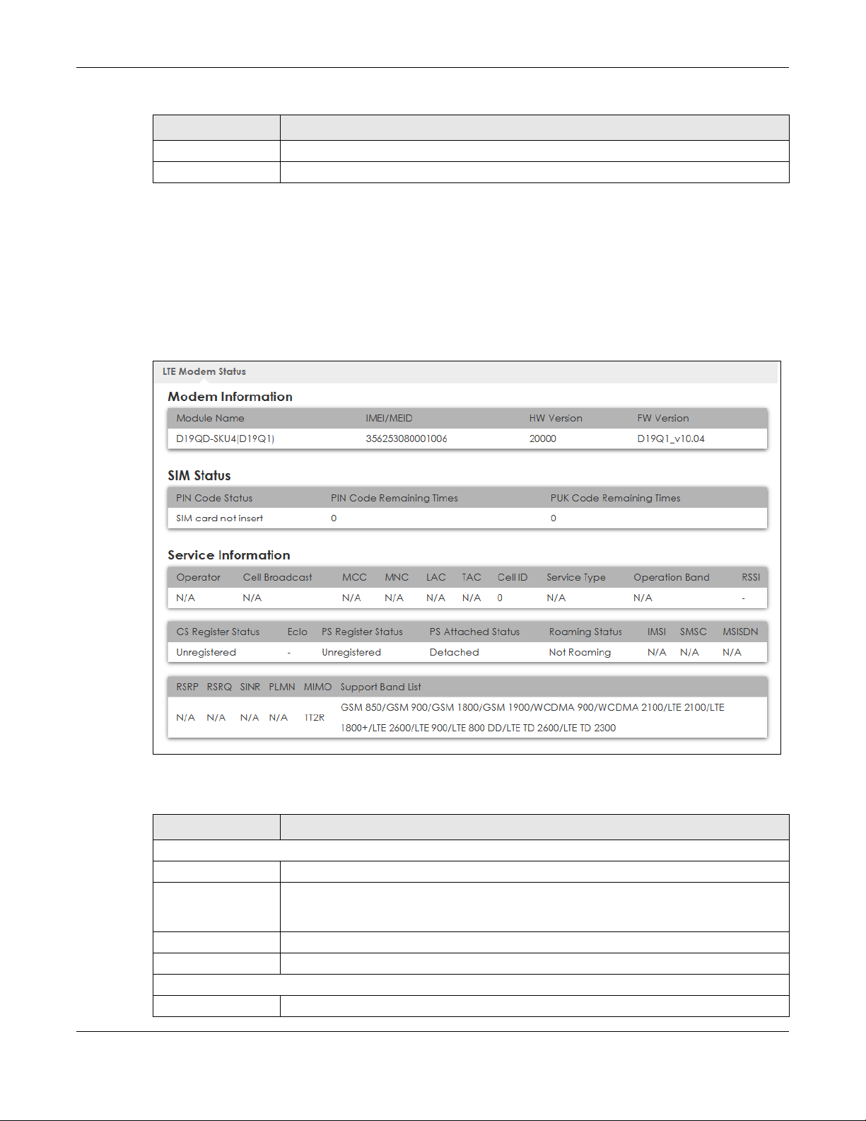
Table 13 Monitor > WLAN Station Status (continued)
LABEL DESCRIPTION
MAC Address This field displays the MAC address of an associated wireless station.
Association Time This field displays the time a wireless station first associated with the LTE5366’s WLAN.
5.8 LTE Modem Status
Click Monitor > LTE Modem Status or the LTE Modem Status (Details...) hyperlink in the Status screen. Use
this screen to view the detailed information about the LTE module, cellular interface, and SIM card. You
can also check the LTE connection status.
Figure 29 Monitor > LTE Modem Status
Chapter 5 Monitor
The following table describes the labels in this screen.
Table 14 Monitor > LTE Modem Status
LABEL DESCRIPTION
Modem Information
Module Name This displays the name of the built-in LTE module.
IMEI/MEID This displays the International Mobile Equipment Number (IMEI) or Mobile Equipment
Identifier (MEID), which is the serial number of the built-in LTE module. It is a unique 15-digit
number used to identify a mobile device.
HW Version This displays the hardware version of the built-in LTE module.
FW Version This displays the firmware version of the built-in LTE module.
SIM Status
SIM This displays the status of the inserted SIM card. N/A displays if there is no SIM card inserted.
LTE5366 Series User’s Guide
51
Page 52

Chapter 5 Monitor
Table 14 Monitor > LTE Modem Status (continued)
LABEL DESCRIPTION
PIN Code Status This displays the status of PIN code authentication.
PIN Code Remaining
Times
PUK Code
Remaining Times
Service Information
Operator This displays the name of the service provider.
Cell Broadcast This displays whether the one-to-many messaging service is available.
MCC This displays the Mobile Country Code (MCC), which is used to identify the country of a
MNC This displays the Mobile Network Code (MNC), which is used in combination with MCC to
LAC This displays the 2-octet Location Area Code (LAC), which is used to identify a location
TAC This displays the Tracking Area Code (TAC), which is to identify a tracking area within a
Physical Cell ID This displays the ID of a cell at the physical layer.
Service Type This displays the type of the mobile network to which the LTE5366 is connecting.
Operation Band This displays the network type and the frequency band used by the mobile network to
RSSI This displays the received signal strength indicator (RSSI), that is, the received signal strength
CS Register Status This displays the Circuit Switched network registration status.
EcIo This displays the ratio (in dB) of the received energy per chip and the interference level.
PS Register Status This displays the packet switched network registration status.
PS Attached Status This displays the Packet switched Domain Attachment status.
Roaming Status This displays whether the LTE5366 is connected to another service provider’s mobile network
IMSI This displays the International Mobile Subscriber Identity (IMSI) stored in the SIM (Subscriber
SMSC This displays the number for Short Message Service Center (SMSC), which stores, forwards
MSISDN This displays the MSISDN (Mobile Subscriber ISDN) number, a phone number assigned to a
RSRP This displays the Reference Signal Receive Power (RSRP), which is the average received
RSRQ This displays the Reference Signal Received Quality (RSRQ), which is the ratio of RSRP to the
SINR This displays the Signal to Interference plus Noise Ratio (SINR). A negative value means more
PLMN This displays the Public Land Mobile Network (PLMN) code of the mobile network.
MIMO This displays the MIMO (Multi-input Multi-output) technology supported by the LTE5366, such
Support Band List This displays the frequency bands that are supported by the LTE5366.
This displays how many times you can enter the PIN code.
This displays how many times you can enter the PUK code.
mobile subscriber.
identify the public land mobile network (PLMN) of a mobile subscriber.
area within a PLMN.
PLMN.
which the LTE5366 is connecting.
in dBm.
using roaming.
Identity Module) card. The SIM card is installed in a mobile device and used for
authenticating a customer to the carrier network. IMSI is a unique 15-digit number used to
identify a user on a network.
and delivers SMS text message.
mobile subscriber to call a mobile device.
power of all Resource Elements (RE) that carry cell-specific Reference Signals (RS) within the
specified bandwidth.
E-UTRA carrier RSSI and indicates the quality of the received reference signal.
noise than signal.
as 1T2R (1 Transmit and 2 Receive paths/antennas) or TM1-TM4 (Transmission Mode 4).
LTE5366 Series User’s Guide
52
Page 53

Chapter 5 Monitor
LTE5366 Series User’s Guide
53
Page 54

6.1 Overview
LAN
This chapter discusses the LTE5366’s WAN screens. Use these screens to configure your LTE5366 for
Internet access.
A WAN (Wide Area Network) connection is an outside connection to another network or the Internet. It
connects your private networks such as a LAN (Local Area Network) and other networks, so that a
computer in one location can communicate with computers in other locations.
3G and 4G standards for the sending and receiving of voice, video, and data in a mobile environment.
You can insert a 3G/4G SIM card and set the LTE5366 to use this 3G/4G connection as your WAN.
Figure 30 LAN/Wireless LAN and Wireless WAN
CHAPTER 6
WAN
6.2 What You Can Do
• Use the Management WAN screen to configure 3G/4G WAN connection settings (Section 6.4 on
page 57).
• Use the Network Scan screen to specify the type of the mobile network to which the LTE5366 is
connected and how you want the LTE5366 to connect to an available mobile network (Section 6.5 on
page 62).
• Use the IPv6 screen to configure the LTE5366’s IPv6 settings (Section 6.6 on page 63).
LTE5366 Series User’s Guide
54
Page 55

Chapter 6 WAN
• Use the PIN Management screen to configure the LTE5366’s PIN settings (Section 6.7 on page 64).
6.3 What You Need To Know
The information in this section can help you configure the screens for your WAN connection, as well as
enable/disable some advanced features of your LTE5366.
3G
3G (Third Generation) is a digital, packet-switched wireless technology. Bandwidth usage is optimized as
multiple users share the same channel and bandwidth is only allocated to users when they send data. It
allows fast transfer of voice and non-voice data and provides broadband Internet access to mobile
devices.
4G
4G is the fourth generation of the mobile telecommunications technology and a successor of 3G. Both
the WiMAX and Long Term Evolution (LTE) standards are the 4G candidate systems. 4G only supports allIP-based packet-switched telephony services and is required to offer gigabit speed access.
DNS Server Address Assignment
Use Domain Name System (DNS) to map a domain name to its corresponding IP address and vice versa,
for instance, the IP address of www.zyxel.com is 204.217.0.2. The DNS server is extremely important
because without it, you must know the IP address of a computer before you can access it.
The LTE5366 can get the DNS server addresses in the following ways.
1 The ISP tells you the DNS server addresses, usually in the form of an information sheet, when you sign up.
If your ISP gives you DNS server addresses, manually enter them in the DNS server fields.
2 If your ISP dynamically assigns the DNS server IP addresses (along with the LTE5366’s WAN IP address), set
the DNS server fields to get the DNS server address from the ISP.
LTE5366 Series User’s Guide
55
Page 56
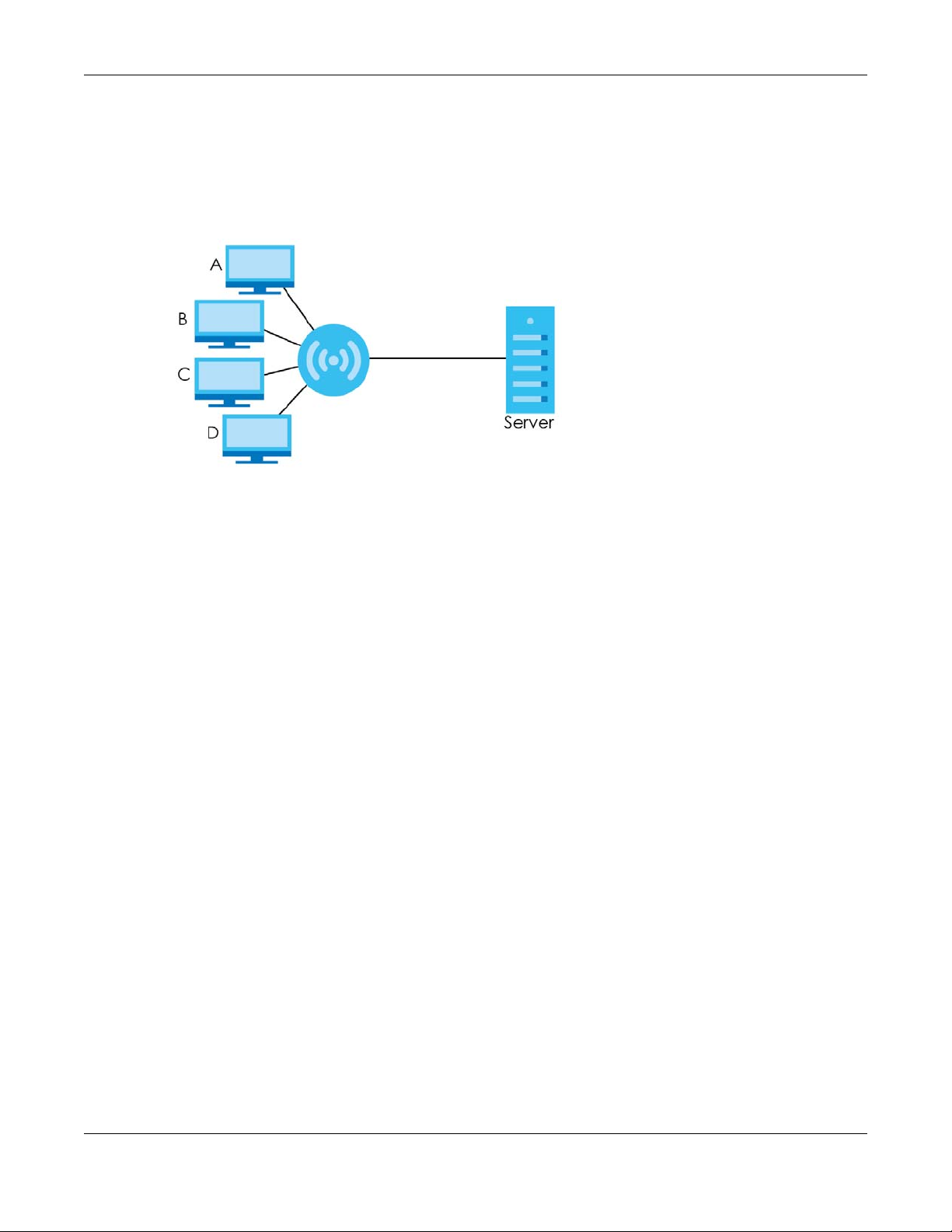
Chapter 6 WAN
Multicast
Traditionally, IP packets are transmitted in one of either two ways - Unicast (1 sender - 1 recipient) or
Broadcast (1 sender - everybody on the network). Multicast delivers IP packets to a group of hosts on
the network - not everybody and not just 1.
Figure 31 Multicast Example
In the multicast example above, systems A and D comprise one multicast group. In multicasting, the
server only needs to send one data stream and this is delivered to systems A and D.
IGMP (Internet Group Multicast Protocol) is a network-layer protocol used to establish membership in a
multicast group - it is not used to carry user data. The LTE5366 supports both IGMP version 1 (IGMP v1),
IGMP version 2 (IGMP v2) and IGMP version 3 (IGMP v3).
At start up, the LTE5366 queries all directly connected networks to gather group membership. After that,
the LTE5366 periodically updates this information. IP multicasting can be enabled/disabled on the
LTE5366 WAN interface in the Web Configurator.
IPv6 Introduction
IPv6 (Internet Protocol version 6), is designed to enhance IP address size and features. The increase in
IPv6 address size to 128 bits (from the 32-bit IPv4 address) allows up to 3.4 x 10
can use IPv4/IPv6 dual stack to connect to IPv4 and IPv6 networks, and supports IPv6 rapid deployment
(6RD).
38
IP addresses. The LTE5366
IPv6 Addressing
The 128-bit IPv6 address is written as eight 16-bit hexadecimal blocks separated by colons (:). This is an
example IPv6 address 2001:0db8:1a2b:0015:0000:0000:1a2f:0000.
IPv6 addresses can be abbreviated in two ways:
• Leading zeros in a block can be omitted. So 2001:0db8:1a2b:0015:0000:0000:1a2f:0000 can be
written as 2001:db8:1a2b:15:0:0:1a2f:0.
• Any number of consecutive blocks of zeros can be replaced by a double colon. A double colon can
only appear once in an IPv6 address. So 2001:0db8:0000:0000:1a2f:0000:0000:0015 can be
written as 2001:0db8::1a2f:0000:0000:0015, 2001:0db8:0000:0000:1a2f::0015,
2001:db8::1a2f:0:0:15 or 2001:db8:0:0:1a2f::15.
LTE5366 Series User’s Guide
56
Page 57
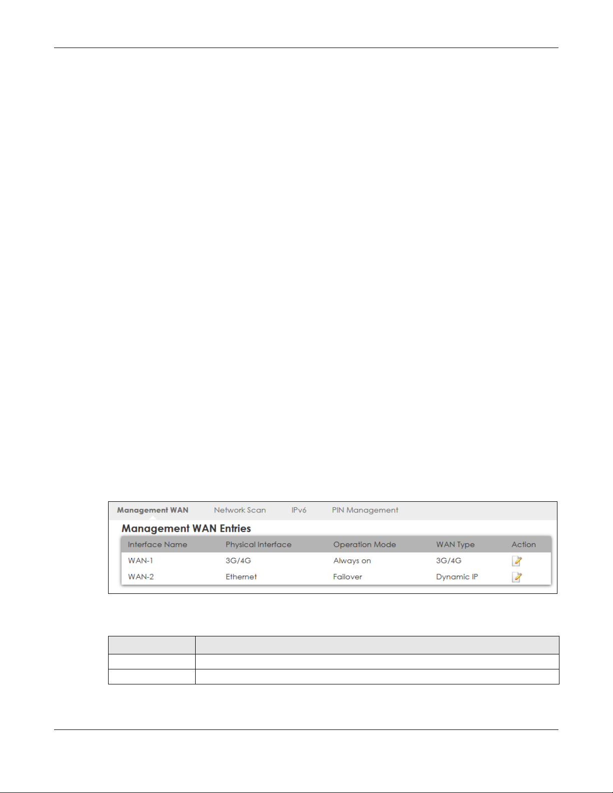
Chapter 6 WAN
IPv6 Prefix and Prefix Length
Similar to an IPv4 subnet mask, IPv6 uses an address prefix to represent the network address. An IPv6
prefix length specifies how many most significant bits (start from the left) in the address compose the
network address. The prefix length is written as “/x” where x is a number. For example,
2001:db8:1a2b:15::1a2f:0/32
means that the first 32 bits (2001:db8) is the subnet prefix.
IPv6 Subnet Masking
Both an IPv6 address and IPv6 subnet mask compose of 128-bit binary digits, which are divided into
eight 16-bit blocks and written in hexadecimal notation. Hexadecimal uses four bits for each character
(1 ~ 10, A ~ F). Each block’s 16 bits are then represented by four hexadecimal characters. For example,
FFFF:FFFF:FFFF:FFFF:FC00:0000:0000:0000.
IPv6 Rapid Deployment
Use IPv6 Rapid Deployment (6rd) when the local network uses IPv6 and the ISP has an IPv4 network.
When the LTE5366 has an IPv4 WAN address, you can enable 6rd to encapsulate IPv6 packets in IPv4
packets to cross the ISP’s IPv4 network.
The LTE5366 generates a global IPv6 prefix from its IPv4 WAN address and tunnels IPv6 traffic to the ISP’s
Border Relay router (BR in the figure) to connect to the native IPv6 Internet. The local network can also
use IPv4 services. The LTE5366 uses it’s configured IPv4 WAN IP to route IPv4 traffic to the IPv4 Internet.
6.4 Management WAN
The summary table shows you the WAN connection configured on the LTE5366. Click Network > WAN >
Management WAN from the Configuration menu.
Figure 32 Configuration > Network > WAN > Management WAN
The following table describes the labels in this screen.
Table 15 Configuration > Network > WAN > Management WAN
LABEL DESCRIPTION
Interface Name This field displays the name of the WAN interface for this connection.
Physical Interface This field displays the type of physical WAN connection.
LTE5366 Series User’s Guide
57
Page 58

Table 15 Configuration > Network > WAN > Management WAN (continued)
LABEL DESCRIPTION
Operation Mode This displays Always on in the active or main WAN interface.
This displays Failover in the passive interface that works as a backup for the Always on WAN
interface. When the connection through the active WAN interface goes down, the LTE5366
will automatically send traffic through the failover interface.
WAN Type This field displays the type of WAN connection.
Action Click the Edit icon to configure the WAN connection settings.
6.4.1 Management WAN Edit
Use this screen to change your LTE5366’s 3G/4G WAN connection settings. Click the Edit icon in the
Configuration > Network > WAN > Management WAN screen.
Chapter 6 WAN
LTE5366 Series User’s Guide
58
Page 59

Chapter 6 WAN
Figure 33 Configuration > Network > WAN > Management WAN Edit
LTE5366 Series User’s Guide
59
Page 60

Chapter 6 WAN
The following table describes the labels in this screen.
Table 16 Configuration > Network > WAN > Management WAN Edit
LABEL DESCRIPTION
Configuration
Port 1 config as WAN
port
Select Enable so Port 1 on the LTE5366 works as a WAN port instead of LAN.
Note: Port 1 is the first yellow port from right to left.
Antenna Select
Connection with SIM Card
Network Type Select the type of network to which you want the LTE5366 to connect.
Band Selection Select Auto so the LTE5366 connects to an available band automatically. When one of
Band List This drop-down list is available when the LTE5366 has a working SIM card, it shows the
Dial-Up Profile Select Auto-Detection to have the LTE5366 use the inserted SIM card’s default settings to
Select External to have the external antennas work as default for signal transmission.
Select Internal to have the internal antennas work as default for signal transmission.
Select 2G Only, 3G Only, or LTE Only to connect to a single network only even if other
networks are available.
Otherwise, select Auto to have the LTE5366 connect to an available network using the
default settings on the SIM card.
them is not available it will automatically connect to another one.
Select Manual to select which bands the LTE5366 connects to.
bands detected using the SIM card.
connect to any available mobile network.
Select Manual-configuration and enter the information provided by your service provider
to connect to the service provider’s mobile network.
APN Connections with different APNs (Access Point Names) may provide different services
(such as Internet access or MMS (Multi-Media Messaging Service)) and charge method.
The corresponding APN automatically displays when you select a pre-defined service
provider.
If you select Manual-configuration in the Dial-Up Profile field, manually enter the APN
provided by your service provider. You can enter up to 32 ASCII printable characters.
Spaces are allowed.
PIN Code A PIN (Personal Identification Number) code is a key to a SIM card. Without the PIN code,
Dial Number This is the phone number (dial string) used to dial up a connection to your service
Account Type the user name (of up to 64 ASCII printable characters) given to you by your service
you cannot use the SIM card.
If your service provider enabled PIN code authentication, enter the 4-digit PIN code
(0000 for example) provided by your service provider. If you enter the PIN code
incorrectly, the SIM card may be blocked by your service provider and you cannot use
the account to access the Internet.
If your service provider disabled PIN code authentication, leave this field blank.
provider’s base station. Your service provider should provide the phone number. For
example, *99# is the dial string to establish a GPRS or 3G/4G connection in Taiwan.
The corresponding phone number automatically displays when you select a pre-defined
service provider.
If you select Others in the Service Provider field, manually enter the phone number
provided by your service provider.
provider.
LTE5366 Series User’s Guide
60
Page 61

Chapter 6 WAN
Table 16 Configuration > Network > WAN > Management WAN Edit (continued)
LABEL DESCRIPTION
Password Type the password (of up to 64 ASCII printable characters) associated with the username
above.
Authentication The LTE5366 supports PAP (Password Authentication Protocol) and CHAP (Challenge
Handshake Authentication Protocol). CHAP is more secure than PAP; however, PAP is
readily available on more platforms
Select an authentication protocol (PAP, or CHAP) used by the service provider.
Otherwise, select Auto to have the LTE5366 accept either CHAP or PAP.
IP Mode Select Dynamic IP if you have a dynamic IP address.
Select Static IP if you have a fixed IP address assigned by your service provider.
IP Address Enter your WAN IP address in this field if you selected Static IP in the IP Mode field.
IP Subnet Mask Enter the subnet mask in this field if you selected Static IP in the IP Mode field.
IP Gateway Enter the gateway IP address in this field if you selected Static IP in the IP Mode field.
Primary DNS Enter the first DNS server address assigned by the service provider.
Secondary DNS Enter the second DNS server address assigned by the service provider.
Roaming 3G/4G roaming is to use your mobile device in an area which is not covered by your
3G/4G Connection Common Configuration
MTU Enter the MTU (Maximum Transmission Unit) of each data packet, in bytes, that can move
IP Passthrough (Celullar
Bridge)
Network Monitoring Select this option to have the LTE5366 test the WAN connection by periodically sending
Loading Check Select this option to check how many packets have been transmitted or received
Check Interval Type a number of seconds (0 to 99999) to set the time interval between checks. Allow
Check Timeout Type the number of seconds (0 to 99999) for your LTE5366 to wait for a response to the
Latency Threshold Type a number of milliseconds (0 to 99999) for the latency threshold. If the specified
Fail Threshold Type how many WAN connection checks can fail (0 to 99999) before the connection is
Target 1 / Target 2 Select DNS1 to have the LTE5366 send a DNS query to the first DNS server address
service provider. Enable roaming to ensure that your LTE5366 is kept connected to the
Internet when you are traveling outside the geographical coverage area of the network
to which you are registered
through the WAN connection.
Select the checkbox to enable WAN IP Passthrough. In the Fixed MAC field, enter the
MAC address of the device that will use the WAN side IP address (public IP address) as
the LTE5366.
DNS Query to a DNS server or sending a ping (ICMP Checking) to either the default
gateway or the addresses you specify in the Target1 and Target2 fields.
through the WAN connection within a time period specified in the Check Interval field.
more time if your destination IP address handles lots of traffic.
ping or DNS query before considering the check to have failed. This setting must be less
than the Check Interval. Use a higher value in this field if your network is busy or
congested.
latency threshold is exceeded, the LTE5366 considers the check to have failed and
makes a new connection after (Latency Threshold * Fail Threshold) seconds.
considered "down" (not connected). The LTE5366 still checks a "down" connection to
detect if it reconnects.
assigned by the service provider.
Select DNS2 to have the LTE5366 send a DNS query to the second DNS server address
assigned by the service provider.
Select Other Host and enter a domain name or IP address of a reliable nearby computer
to have the LTE5366 ping that address.
LTE5366 Series User’s Guide
61
Page 62

Table 16 Configuration > Network > WAN > Management WAN Edit (continued)
LABEL DESCRIPTION
IGMP Select Auto to enable multicasting. This applies to traffic routed from the WAN to the LAN.
IGMP Proxy This field is available only when IGMP is enabled.
IP Type Select IPv4 if you want the LTE5366 to run IPv4 only.
Save Click Save to save your changes back to the LTE5366.
Undo Click Undo to reload the previous configuration for this screen.
6.5 Network Scan
Chapter 6 WAN
Select Disable to turn off this feature. This may cause incoming traffic to be dropped or
sent to all connected network devices
Select this option to have the LTE5366 act as an IGMP proxy on this connection. This
allows the LTE5366 to get subscribing information and maintain a joined member list for
each multicast group. It can reduce multicast traffic significantly.
Select IPv6 if you want the LTE5366 to run IPv6 only.
Select IPv4/IPv6 if you want the LTE5366 to run IPv4 and IPv6 at the same time.
Use this screen to set how you want the LTE5366 to connect to an available mobile network. Click
Network > WAN > Network Scan from the Configuration menu.
Figure 34 Configuration > Network > WAN > Network Scan
The following table describes the labels in this screen.
Table 17 Configuration > Network > WAN > Network Scan
LABEL DESCRIPTION
Physical Interface This shows the type of the interface used by the WAN connection.
Network Type Select the type of the network (4G only) to which you want the LTE5366 to connect when
there is a SIM card inserted.
LTE5366 Series User’s Guide
62
Page 63

Chapter 6 WAN
Table 17 Configuration > Network > WAN > Network Scan (continued)
LABEL DESCRIPTION
Scan Approach Select Auto to have the LTE5366 connect to an available network using the default
settings on the SIM card. If the currently registered mobile network is not available or the
mobile network’s signal strength is too low, the LTE5366 switches to another available
mobile network.
Select Manually to search for and select the mobile network(s) to which you want the
LTE5366 to connect.
Network Provider List This table is available only when you set Scan Approach to Manually.
Click Scan to search for available mobile networks based on the network type you
selected.
Click Apply to save your changes in the Action field.
Provider Name This shows the name of the service provider.
Mobile System This shows the mobile telecommunications standard supported by the mobile network.
Network Status This shows whether the mobile network is available.
Action Click Select to have the LTE5366 establish a connection to the selected mobile network.
Cancel Click Cancel to reload the previous configuration for this screen.
Refresh Click Refresh to update this screen.
Apply Click Apply to save your changes back to the LTE5366.
6.6 IPv6
Use this screen to configure the LTE5366’s IPv6 settings. Click Network > WAN > IPv6 from the
Configuration menu.
Figure 35 Configuration > Network > WAN > IPv6
LTE5366 Series User’s Guide
63
Page 64

Chapter 6 WAN
The following table describes the labels in this screen.
Table 18 Configuration > Network > WAN > IPv6
LABEL DESCRIPTION
IPv6 Select Enable to allow the LTE5366 to run IPv6. Otherwise, select Disable.
IPv6 Connection Select DHCPv6 if you want to obtain an IPv6 address from a DHCPv6 server.
DNS Setting Select Obtain DNS Server address Automatically to have the LTE5366 get the IPv6 DNS
Primary DNS Address
Secondary DNS
Address
LAN IPv6 Address Enter the IPv6 address for the LTE5366 LAN interface in this field.
LAN IPv6 Link-Local
Address
Autoconfiguration Click Enable if you want the devices on your local area network to obtain network
Autoconfiguration Type Select Stateless if you want the LTE5366 interface to automatically generate a link-local
IPv6 Address
Range(Start)
IPv6 Address
Range(End)
Cancel Click Cancel to reload the previous configuration for this screen.
Apply Click Apply to save your changes back to the LTE5366.
server addresses from the ISP automatically.
Select Use the following DNS address to have the LTE5366 use the IPv6 DNS server
addresses you configure manually.
Enter the first IPv6 DNS server address assigned by the ISP.
Enter the second IPv6 DNS server address assigned by the ISP.
This shows the IPv6 Link-local address in the LAN side. This is used by LTE5366 when
communicating with neighboring devices on the same link. It allows IPv6-capable
devices to communicate with each other in the LAN side.
address that are not managed by a DHCPv6 server. Otherwise, select Disable.
address via stateless auto configuration.
Select Stateful (DHCPv6) when the devices connected to your LAN needs to have their
TCP/IP configuration set to DHCPv6 or obtain an IPv6 address automatically.
If you select Stateful (DHCPv6), specify the range of IPv6 addresses from which the
DHCPv6 server assigns to the clients. Enter the smallest value of the last block of the IPv6
addresses which are to be allocated.
If you select Stateful (DHCPv6), specify the range of IPv6 addresses from which the
DHCPv6 server assigns to the clients. Enter the largest value of the last block of the IPv6
addresses which are to be allocated.
6.7 PIN Management
Use this screen to enable PIN authentication and configure the PIN code. Click Configuration > Network
> WAN > PIN Management from the Configuration menu.
Figure 36 Configuration > Network > WAN > PIN Management
LTE5366 Series User’s Guide
64
Page 65

Chapter 6 WAN
The following table describes the labels in this screen.
Table 19 Configuration > Network > WAN > PIN Management
LABEL DESCRIPTION
PIN Code Request
function
SIM PIN Code If you select Enable, enter the 4-digit PIN code (0000 for example) provided by your ISP
Apply Click Apply to save your changes back to the LTE5366.
Cancel Click Cancel to reload the previous configuration for this screen.
Select Enable to turn on PIN code authentication. A PIN (Personal Identification Number)
code is a key to a SIM card. Without the PIN code, you cannot use the SIM card.
Select Disable to turn off PIN code authentication.
for the inserted SIM card.
LTE5366 Series User’s Guide
65
Page 66

7.1 Overview
This chapter discusses how to configure the wireless network settings in your LTE5366.
See the appendices for more detailed information about wireless networks.
The following figure provides an example of a wireless network.
Figure 37 Example of a Wireless Network
CHAPTER 7
Wireless LAN
The wireless network is the part in the blue circle. In this wireless network, devices A and B are called
wireless clients. The wireless clients use the access point (AP) to interact with other devices (such as the
printer) or with the Internet. Your LTE5366 is the AP.
7.1.1 What You Can Do
• Use the General screen to turn the wireless connection on or off, set up wireless security between the
LTE5366 and the wireless clients, and make other basic configuration changes (Section 7.2 on page
69).
• Use the More AP screen to set up multiple wireless networks on your LTE5366 (Section 7.4 on page 76).
• Use the MAC Filter screen to allow or deny wireless stations based on their MAC addresses from
connecting to the LTE5366 (Section 7.5 on page 78).
LTE5366 Series User’s Guide
66
Page 67

• Use the Advanced screen to allow intra-BSS networking and set the RTS/CTS Threshold (Section 7.6 on
page 80).
• Use the QoS screen to ensure Quality of Service (QoS) in your wireless network (Section 7.7 on page
81).
• Use the WPS screen to quickly set up a wireless network with strong security, without having to
configure security settings manually (Section 7.8 on page 82).
• Use the WPS Station screen to add a wireless station using WPS (Section 7.9 on page 83).
• Use the Scheduling screen to set the times your wireless LAN is turned on and off (Section 7.10 on
page 84).
• Use the WDS screen to configure the LTE5366’s WDS settings (Section 7.11 on page 85).
7.1.2 What You Should Know
Every wireless network must follow these basic guidelines.
• Every wireless client in the same wireless network must use the same SSID.
The SSID is the name of the wireless network. It stands for Service Set IDentity.
• If two wireless networks overlap, they should use different channels.
Like radio stations or television channels, each wireless network uses a specific channel, or frequency,
to send and receive information.
• Every wireless client in the same wireless network must use security compatible with the AP.
Security stops unauthorized devices from using the wireless network. It can also protect the
information that is sent in the wireless network.
Chapter 7 Wireless LAN
Wireless Security Overview
The following sections introduce different types of wireless security you can set up in the wireless
network.
SSID
Normally, the AP acts like a beacon and regularly broadcasts the SSID in the area. You can hide the
SSID instead, in which case the AP does not broadcast the SSID. In addition, you should change the
default SSID to something that is difficult to guess.
This type of security is fairly weak, however, because there are ways for unauthorized devices to get the
SSID. In addition, unauthorized devices can still see the information that is sent in the wireless network.
MAC Address Filter
Every wireless client has a unique identification number, called a MAC address.1 A MAC address is
usually written using twelve hexadecimal characters
To get the MAC address for each wireless client, see the appropriate User’s Guide or other
documentation.
1. Some wireless devices, such as scanners, can detect wireless networks but cannot use wireless networks. These
kinds of wireless devices might not have MAC addresses.
2. Hexadecimal characters are 0, 1, 2, 3, 4, 5, 6, 7, 8, 9, A, B, C, D, E, and F.
2
; for example, 00A0C5000002 or 00:A0:C5:00:00:02.
LTE5366 Series User’s Guide
67
Page 68

Chapter 7 Wireless LAN
You can use the MAC address filter to tell the AP which wireless clients are allowed or not allowed to use
the wireless network. If a wireless client is allowed to use the wireless network, it still has to have the
correct settings (SSID, channel, and security). If a wireless client is not allowed to use the wireless
network, it does not matter if it has the correct settings.
This type of security does not protect the information that is sent in the wireless network. Furthermore,
there are ways for unauthorized devices to get the MAC address of an authorized wireless client. Then,
they can use that MAC address to use the wireless network.
User Authentication
You can make every user log in to the wireless network before they can use it. This is called user
authentication. However, every wireless client in the wireless network has to support IEEE 802.1x to do
this.
For wireless networks, there are two typical places to store the user names and passwords for each user.
• In the AP: this feature is called a local user database or a local database.
• In a RADIUS server: this is a server used in businesses more than in homes.
If your AP does not provide a local user database and if you do not have a RADIUS server, you cannot
set up user names and passwords for your users.
Unauthorized devices can still see the information that is sent in the wireless network, even if they cannot
use the wireless network. Furthermore, there are ways for unauthorized wireless users to get a valid user
name and password. Then, they can use that user name and password to use the wireless network.
Local user databases also have an additional limitation that is explained in the next section.
Encryption
Wireless networks can use encryption to protect the information that is sent in the wireless network.
Encryption is like a secret code. If you do not know the secret code, you cannot understand the
message.
The types of encryption you can choose depend on the type of user authentication. (See page 68 for
information about this.)
Table 20 Types of Encryption for Each Type of Authentication
NO AUTHENTICATION RADIUS SERVER
Weakest No Security WPA
Static WEP
WPA-PSK
Strongest WPA2-PSK WPA2
For example, if the wireless network has a RADIUS server, you can choose WPA or WPA2. If users do not
log in to the wireless network, you can choose no encryption, Static WEP, WPA-PSK, or WPA2-PSK.
Usually, you should set up the strongest encryption that every wireless client in the wireless network
supports. For example, suppose the AP does not have a local user database, and you do not have a
RADIUS server. Therefore, there is no user authentication. Suppose the wireless network has two wireless
LTE5366 Series User’s Guide
68
Page 69

Chapter 7 Wireless LAN
clients. Device A only supports WEP, and device B supports WEP and WPA. Therefore, you should set up
Static WEP in the wireless network.
Note: It is recommended that wireless networks use WPA-PSK, WPA, or stronger encryption.
IEEE 802.1x and WEP encryption are better than none at all, but it is still possible for
unauthorized devices to figure out the original information pretty quickly.
Note: It is not possible to use WPA-PSK, WPA or stronger encryption with a local user database.
In this case, it is better to set up stronger encryption with no authentication than to set
up weaker encryption with the local user database.
When you select WPA2 or WPA2-PSK in your LTE5366, you can also select an option (WPA/WPA-PSK
Compatible) to support WPA/WPA-PSK as well. In this case, if some wireless clients support WPA and
some support WPA2, you should set up WPA2-PSK or WPA2 (depending on the type of wireless network
login) and select the WPA/WPA-PSK Compatible option in the LTE5366.
Many types of encryption use a key to protect the information in the wireless network. The longer the
key, the stronger the encryption. Every wireless client in the wireless network must have the same key.
WPS
WiFi Protected Setup (WPS) is an industry standard specification, defined by the WiFi Alliance. WPS
allows you to quickly set up a wireless network with strong security, without having to configure security
settings manually. Depending on the devices in your network, you can either press a button (on the
device itself, or in its configuration utility) or enter a PIN (Personal Identification Number) in the devices.
Then, they connect and set up a secure network by themselves. See how to set up a secure wireless
network using WPS in the Section 4.2 on page 34.
7.2 General Wireless LAN Screen
Use this screen to configure the SSID and wireless security of the wireless LAN.
Note: If you are configuring the LTE5366 from a computer connected to the wireless LAN and
you change the LTE5366’s SSID, channel or security settings, you will lose your wireless
connection when you press Apply to confirm. You must then change the wireless
settings of your computer to match the LTE5366’s new settings.
Click Configuration > Network > Wireless LAN to open the General screen.
LTE5366 Series User’s Guide
69
Page 70

Chapter 7 Wireless LAN
Figure 38 Configuration > Network > Wireless LAN > General
The following table describes the general wireless LAN labels in this screen.
Table 21 Configuration > Network > Wireless LAN > General
LABEL DESCRIPTION
Wireless Setup - 2.4G / Wireless Setup - 5G
Wireless LAN Status Select Enable to activate the 2.4GHz/5GHz wireless LAN. Select Disable to turn it off.
You can also enable or disable the 2.4GHz/5GHz wireless LANs by using the WLAN/WPS button
located on the side panel of the LTE5366.
Name (SSID) The SSID (Service Set IDentity) identifies the Service Set with which a wireless client is
associated. Enter a descriptive name (up to 32 printable characters found on a typical English
language keyboard) for the wireless LAN.
Hide SSID Select this check box to hide the SSID in the outgoing beacon frame so a station cannot
obtain the SSID through scanning using a site survey tool.
LTE5366 Series User’s Guide
70
Page 71

Chapter 7 Wireless LAN
Table 21 Configuration > Network > Wireless LAN > General (continued)
LABEL DESCRIPTION
Channel Selection Set the operating frequency/channel depending on your particular region.
Select a channel from the drop-down list box. The options vary depending on the frequency
band and the country you are in.
Refer to the Connection Wizard chapter for more information on channels. This option is only
available if Auto Channel Selection is disabled.
Enable Auto
Channel Selection
Operating
Channel
Channel Width Select the wireless channel width used by LTE5366.
Select this check box for the LTE5366 to automatically choose the channel with the least
interference. Deselect this check box if you wish to manually select the channel using the
Channel Selection field.
This displays the operating frequency/channel depending on your particular region.
A standard 20 MHz channel(HT20) offers transfer speeds of up to 144Mbps (2.4GHz) or
217Mbps(5GHZ) whereas a 40MHz channel(HT40) uses two standard channels and offers
speeds of up to 300Mbps (2.4GHz) or 450Mbps (5GHZ). An IEEE 802.11ac-specific 80MHz
channel (HT80) offers speeds of up to 1.3Gbps.
Because not all devices support 40 MHz and/or 80 MHz channels, select Auto to allow the
LTE5366 to adjust the channel bandwidth automatically.
HT40 (channel bonding or dual channel) bonds two adjacent radio channels to increase
throughput. A HT80 channel consists of two adjacent 40 MHz channels. The wireless clients
must also support HT40 or HT80. It is often better to use the 20 MHz setting in a location where
the environment hinders the wireless signal.
Select HT20 if you want to lessen radio interference with other wireless devices in your
neighborhood or the wireless clients do not support channel bonding.
802.11 Mode In Wireless Setup for 2.4Ghz network you can select from the following:
• 802.11b Only: allows either IEEE 802.11b compliant WLAN devices to associate with the
LTE5366. In this mode, all wireless devices can only transmit at the data rates supported by
IEEE 802.11b.
• 802.11g Only: allows IEEE 802.11g compliant WLAN devices to associate with the Device.
IEEE 802.11b compliant WLAN devices can associate with the LTE5366 only when they use
the short preamble type.
• 802.11n Only: allows IEEE 802.11n compliant WLAN devices to associate with the LTE5366.
This can increase transmission rates, although IEEE 802.11b or IEEE 802.11g clients will not
be able to connect to the LTE5366.
• 802.11b/g Mixed: allows either IEEE 802.11b or IEEE 802.11g compliant WLAN devices to
associate with the LTE5366. The LTE5366 adjusts the transmission rate automatically
according to the wireless standard supported by the wireless devices.
• 802.11g/n Mixed: allows either IEEE 802.11g or IEEE 802.11n compliant WLAN devices to
associate with the LTE5366. The transmission rate of your LTE5366 might be reduced.
• 802.11b/g/n Mixed: allows IEEE802.11b, IEEE802.11g and IEEE802.11n compliant WLAN
devices to associate with the LTE5366. The transmission rate of your LTE5366 might be
reduced.
In Wireless Setup for 5Ghz network you can select from the following:
• 802.11a Only: allows only IEEE 802.11a compliant WLAN devices to associate with the
LTE5366.
• 802.11n Only: allows IEEE 802.11n compliant WLAN devices to associate with the LTE5366.
This can increase transmission rates, although IEEE 802.11a clients will not be able to
connect to the LTE5366.
• 802.11a/n Mixed: allows both IEEE802.11n and IEEE802.11a compliant WLAN devices to
associate with the LTE5366. The transmission rate of your LTE5366 might be reduced.
• 802.11a/n/ac Mixed: allows both IEEE802.11a, IEEE802.11n and IEEE802.11ac compliant
WLAN devices to associate with the LTE5366. The transmission rate of your LTE5366 might
be reduced.
Security - 2.4G / Security - 5G
LTE5366 Series User’s Guide
71
Page 72

Table 21 Configuration > Network > Wireless LAN > General (continued)
LABEL DESCRIPTION
Security Mode Select WPA2-PSK, WPA/WPA2 to add security on this wireless network. The wireless clients
which want to associate to this network must have same wireless security settings as this
device. After you select to use a security, additional options appears in this screen. See
Section 7.3 on page 72 for detailed information on different security modes. Or you can select
Open to allow any client to associate this network without authentication.
Note: If the WPS function is enabled (default), only Open and WPA2-PSK are
available in this field.
Apply Click Apply to save your changes back to the LTE5366.
Cancel Click Cancel to reload the previous configuration for this screen.
See the rest of this chapter for information on the other labels in this screen.
7.3 Wireless Security
The screen varies depending on what you select in the Security Mode field.
Chapter 7 Wireless LAN
7.3.1 No Security
Select Open to allow wireless clients to communicate with the access points without any data
encryption.
Note: If you do not enable any wireless security on your LTE5366, your network is accessible to
any wireless networking device that is within range.
LTE5366 Series User’s Guide
72
Page 73
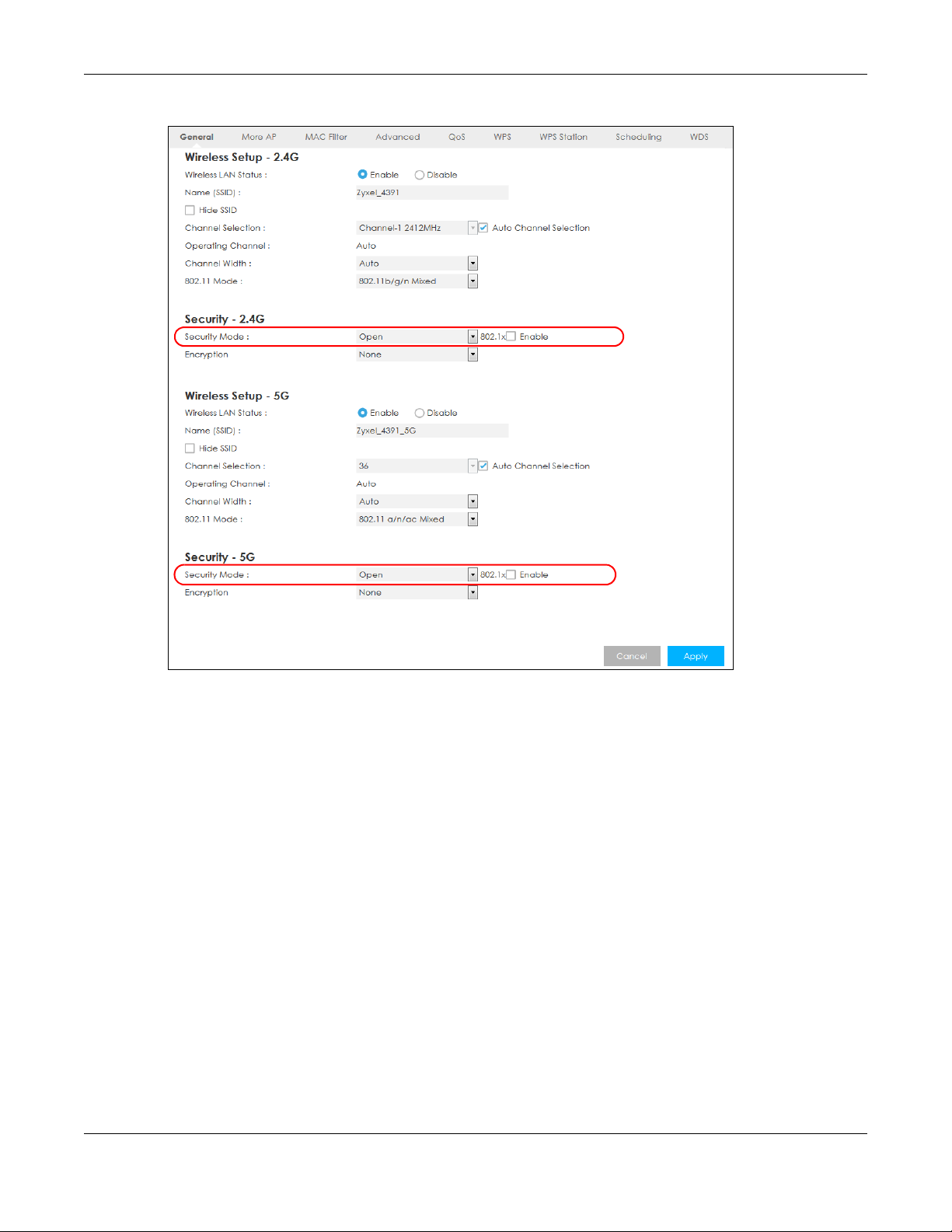
Chapter 7 Wireless LAN
Figure 39 Configuration > Network > Wireless LAN > General: No Security
7.3.2 WPA2-PSK
Select WPA2-PSK from the Security Mode list.
LTE5366 Series User’s Guide
73
Page 74

Chapter 7 Wireless LAN
Figure 40 Network > Wireless LAN > General: WPA2-PSK
The following table describes the labels in this screen.
Table 22 Network > Wireless LAN > General: WPA2-PSK
LABEL DESCRIPTION
Security Mode Select WPA2-PSK to enable data encryption.
Encryption Select the encryption type of data encryption.
Select AES if your wireless clients can all use AES.
Select TKIP / AES to allow the wireless clients to use either TKIP or AES.
Pre-Shared Key WPA2-PSK uses a simple common password for authentication.
Type a pre-shared key from 8 to 63 case-sensitive keyboard characters.
Group Key Update
Timer
Apply Click Apply to save your changes back to the LTE5366.
Cancel Click Cancel to reload the previous configuration for this screen.
The Group Key Update Timer is the rate at which the AP sends a new group key out to all
clients.
The default is 3600 seconds (60 minutes).
LTE5366 Series User’s Guide
74
Page 75

7.3.3 WPA/WPA2
Select WPA or WPA2 from the Security Mode list.
Note: WPA or WPA2 is not available if you enable WPS before you configure WPA or WPA2 in
the Wireless LAN > General screen.
Figure 41 Configuration > Network > Wireless LAN > General: WPA / WPA2
Chapter 7 Wireless LAN
LTE5366 Series User’s Guide
75
Page 76

Chapter 7 Wireless LAN
The following table describes the labels in this screen.
Table 23 Configuration > Network > Wireless LAN > General: WPA / WPA2
LABEL DESCRIPTION
Security Mode Select WPA or WPA2 to enable data encryption.
RADIUS Server
RADIUS Server IP
RADIUS Server Port
RADIUS Shared Key
Encryption Select the encryption type of data encryption.
Group Key Update
Time
Apply Click Apply to save your changes back to the LTE5366.
Cancel Click Cancel to reload the previous configuration for this screen.
Enter the IP address of the RADIUS server to be used for authentication.
Enter the port number of the RADIUS server to be used for authentication.
Enter the shared secret password of the RADIUS server to be used for authentication.
Select AES if your wireless clients can all use AES.
Select TKIP / AES to allow the wireless clients to use either TKIP or AES.
The WPA Group Key Update Timer is the rate at which the AP (if using WPA-PSK key
management) or RADIUS server (if using WPA key management) sends a new group key
out to all clients. The re-keying process is the WPA equivalent of automatically changing
the WEP key for an AP and all stations in a WLAN on a periodic basis. Setting of the WPA
Group Key Update Timer is also supported in WPA-PSK mode. The default setting is 3600
seconds (60 minutes).
7.4 More AP Screen
This screen allows you to enable and configure multiple wireless networks and guest wireless network
settings on the LTE5366.
You can configure up to four SSIDs to enable multiple BSSs (Basic Service Sets) on the LTE5366. This allows
you to use one access point to provide several BSSs simultaneously. You can then assign varying security
types to different SSIDs. Wireless clients can use different SSIDs to associate with the same access point.
Click Configuration > Network > Wireless LAN > More AP. The following screen displays.
Figure 42 Configuration > Network > Wireless LAN > More AP
LTE5366 Series User’s Guide
76
Page 77

The following table describes the labels in this screen.
Table 24 Configuration > Network > Wireless LAN > More AP
LABEL DESCRIPTION
# This is the index number of each SSID profile.
Status This shows whether the SSID profile is active (a yellow bulb) or not (a gray bulb).
SSID An SSID profile is the set of parameters relating to one of the LTE5366’s BSSs. The SSID (Service Set
Security This field indicates the security mode of the SSID profile.
Edit Click the Edit icon to configure the SSID profile.
7.4.1 More AP Edit
Use this screen to edit an SSID profile. Click the Edit icon next to an SSID in the More AP screen. The
following screen displays.
Figure 43 Configuration > Network > Wireless LAN > More AP: Edit
Chapter 7 Wireless LAN
IDentifier) identifies the Service Set with which a wireless device is associated.
This field displays the name of the wireless profile on the network. When a wireless client scans
for an AP to associate with, this is the name that is broadcast and seen in the wireless client
utility.
The following table describes the labels in this screen.
Table 25 Configuration > Network > Wireless LAN > More AP: Edit
LABEL DESCRIPTION
Active Select this to activate the SSID profile.
Name (SSID) The SSID (Service Set IDentity) identifies the Service Set with which a wireless client is associated.
Enter a descriptive name (up to 32 printable characters found on a typical English language
keyboard) for the wireless LAN.
Hide SSID Select this check box to hide the SSID in the outgoing beacon frame so a station cannot obtain
the SSID through scanning using a site survey tool.
LTE5366 Series User’s Guide
77
Page 78

Chapter 7 Wireless LAN
Table 25 Configuration > Network > Wireless LAN > More AP: Edit (continued)
LABEL DESCRIPTION
Intra-BSS Traffic A Basic Service Set (BSS) exists when all communications between wireless clients or between a
wireless client and a wired network client go through one access point (AP).
Intra-BSS traffic is traffic between wireless clients in the BSS. When Intra-BSS is enabled, wireless
clients can access the wired network and communicate with each other. When Intra-BSS is
disabled, wireless clients can still access the wired network but cannot communicate with each
other.
WMM QoS Check this to have the LTE5366 automatically give a service a priority level according to the ToS
value in the IP header of packets it sends.
WMM QoS (Wifi MultiMedia Quality of Service) gives high priority to voice and video, which
makes them run more smoothly.
Security Mode Select WPA2-PSK, WPA/WPA2 to add security on this wireless network. The wireless clients which
want to associate to this network must have same wireless security settings as this device. After
you select to use a security, additional options appears in this screen. See Section 7.3 on page
72 for detailed information on different security modes. Or you can select Open to allow any
client to associate this network without authentication.
Note: If the WPS function is enabled (default), only Open and WPA2-PSK are
available in this field.
Encryption Select the encryption type of data encryption.
Select AES if your wireless clients can all use AES.
Select TKIP / AES to allow the wireless clients to use either TKIP or AES.
Pre-Shared Key Type a password the wireless stations need to enter to connect to the wireless network.
Group Key
Update Timer
Cancel Click Cancel to reload the previous configuration for this screen.
Apply Click Apply to save your changes back to the LTE5366.
The WPA Group Key Update Timer is the rate at which the AP (if using WPA-PSK key
management) or RADIUS server (if using WPA key management) sends a new group key out to
all clients. The re-keying process is the WPA equivalent of automatically changing the WEP key
for an AP and all stations in a WLAN on a periodic basis. Setting of the WPA Group Key Update
Timer is also supported in WPA-PSK mode. The default setting is 3600 seconds (60 minutes).
7.5 MAC Filter Screen
The MAC filter screen allows you to configure the LTE5366 to give exclusive access to devices (Allow) or
exclude devices from accessing the LTE5366 (Deny). Every Ethernet device has a unique MAC (Media
Access Control) address. The MAC address is assigned at the factory and consists of six pairs of
hexadecimal characters, for example, 00:A0:C5:00:00:02. You need to know the MAC address of the
devices to configure this screen.
To change your LTE5366’s MAC filter settings, click Configuration > Network > Wireless LAN > MAC Filter.
The screen appears as shown.
LTE5366 Series User’s Guide
78
Page 79

Chapter 7 Wireless LAN
Figure 44 Configuration > Network > Wireless LAN > MAC Filter
The following table describes the labels in this menu.
Table 26 Configuration > Network > Wireless LAN > MAC Filter
LABEL DESCRIPTION
MAC Address
Filter
Filter Action Define the filter action for the list of MAC addresses in the MAC Filter Summary table.
MAC Filter Summary
Set This is the index number of the MAC address.
MAC Address Enter the MAC address of the wireless station that are allowed or denied access to the LTE5366.
Apply Click Apply to save your changes back to the LTE5366.
Cancel Click Cancel to reload the previous configuration for this screen.
Select to turn on (Enable) or off (Disable) MAC address filtering.
Select Allow to permit access to the LTE5366, MAC addresses not listed will be denied access to
the LTE5366.
Select Deny to block access to the LTE5366, MAC addresses not listed will be allowed to access
the LTE5366.
LTE5366 Series User’s Guide
79
Page 80
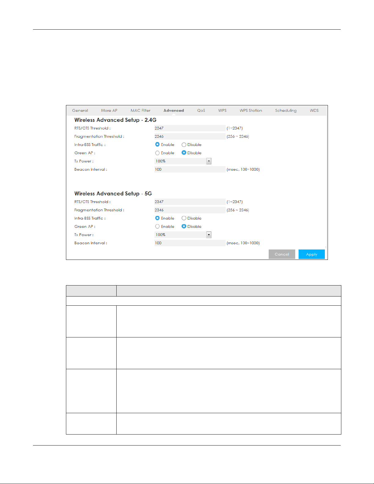
Chapter 7 Wireless LAN
7.6 Wireless LAN Advanced Screen
Use this screen to allow wireless advanced features, such as the output power, RTS/CTS Threshold
settings.
Click Configuration > Network > Wireless LAN > Advanced. The screen appears as shown.
Figure 45 Configuration > Network > Wireless LAN > Advanced
The following table describes the labels in this screen.
Table 27 Configuration > Network > Wireless LAN > Advanced
LABEL DESCRIPTION
Advanced 2.4G Wireless Settings / Advanced 5G Wireless Settings
RTS/CTS Threshold Data with its frame size larger than this value will perform the RTS (Request To Send)/ CTS
(Clear To Send) handshake.
This field is not configurable and the LTE5366 automatically changes to use the maximum
value if you select 802.11n, 802.11gn or 802.11bgn in the Wireless LAN > General screen.
Fragmentation
Threshold
Intra-BSS Traffic A Basic Service Set (BSS) exists when all communications between wireless clients or between
Green AP Select Enable to reduce the power consumption by adjusting the output power. The LTE5366
The threshold (number of bytes) for the fragmentation boundary for directed messages. It is
the maximum data fragment size that can be sent.
This field is not configurable and the LTE5366 automatically changes to use the maximum
value if you select 802.11n, 802.11gn or 802.11bgn in the Wireless LAN > General screen.
a wireless client and a wired network client go through one access point (AP).
Intra-BSS traffic is traffic between wireless clients in the BSS. When Intra-BSS is enabled, wireless
clients can access the wired network and communicate with each other. When Intra-BSS is
disabled, wireless clients can still access the wired network but cannot communicate with
each other.
reduces the output power of the transmitter from about 260mA to 188mA when there is no
IEEE 802.11 wireless clients associated with the LTE5366 wireless network.
LTE5366 Series User’s Guide
80
Page 81

Chapter 7 Wireless LAN
Table 27 Configuration > Network > Wireless LAN > Advanced (continued)
LABEL DESCRIPTION
Tx Power Set the output power of the LTE5366 in this field. If there is a high density of APs in an area,
decrease the output power of the LTE5366 to reduce interference with other APs. Select one
of the following 100%, 90%, 75%, 50%, 25% or 10%.
Beacon Interval When a wirelessly networked device sends a beacon, it includes with it a beacon interval. This
Apply Click Apply to save your changes back to the LTE5366.
Cancel Click Cancel to reload the previous configuration for this screen.
specifies the time period before the device sends the beacon again. The interval tells
receiving devices on the network how long they can wait in low-power mode before waking
up to handle the beacon. A high value helps save current consumption of the access point.
7.7 Quality of Service (QoS) Screen
The QoS screen allows you to automatically give a service (such as VoIP and video) a priority level.
Click Configuration > Network > Wireless LAN > QoS. The following screen appears.
Figure 46 Configuration > Network > Wireless LAN > QoS
The following table describes the labels in this screen.
Table 28 Configuration > Network > Wireless LAN > QoS
LABEL DESCRIPTION
WMM QoS (2.4G) Select Enable to have the LTE5366 automatically give a service a priority level according
WMM QoS (5G) Select Enable to have the LTE5366 automatically give a service a priority level according
Apply Click Apply to save your changes to the LTE5366.
Cancel Click Cancel to reload the previous configuration for this screen.
to the ToS value in the IP header of packets it sends. WMM QoS (Wifi MultiMedia Quality of
Service) gives high priority to voice and video, which makes them run more smoothly.
This field is not configurable and the LTE5366 automatically enables WMM QoS if you
select 802.11n, 802.11g/n Mixed, or 802.11b/g/n Mixed in the Wireless LAN > General
screen.
to the ToS value in the IP header of packets it sends. WMM QoS (Wifi MultiMedia Quality of
Service) gives high priority to voice and video, which makes them run more smoothly.
This field is not configurable and the LTE5366 automatically enables WMM QoS if you
select 802.11n, 802.11a/n Mixed, or 802.11a/n/ac Mixed in the Wireless LAN > General
screen.
LTE5366 Series User’s Guide
81
Page 82

7.8 WPS Screen
Use this screen to enable/disable WPS, view or generate a new PIN number and check current WPS
status. To open this screen, click Configuration > Network > Wireless LAN > WPS.
Note: With WPS, wireless clients can only connect to the wireless network using the first SSID on
the LTE5366.
Figure 47 Configuration > Network > Wireless LAN > WPS
Chapter 7 Wireless LAN
The following table describes the labels in this screen.
Table 29 Configuration > Network > Wireless LAN > WPS
LABEL DESCRIPTION
WPS Setup 2.4G / 5G
WPS Select Enable to turn on the WPS feature. Otherwise, select Disable.
PIN Code Select Enable so the LTE5366 can connect by WPS using the PIN Configuration Method.
Select Disable so it can only connect by WPS using the Push Button Method.
PIN Number This is the WPS PIN (Personal Identification Number) of the LTE5366. Enter this PIN in the
configuration utility of the device you want to connect to the LTE5366 using WPS.
The PIN is not necessary when you use WPS push-button method.
Click Generate to generate a new PIN number.
WPS Status - 2.4G / WPS Status - 5G
LTE5366 Series User’s Guide
82
Page 83
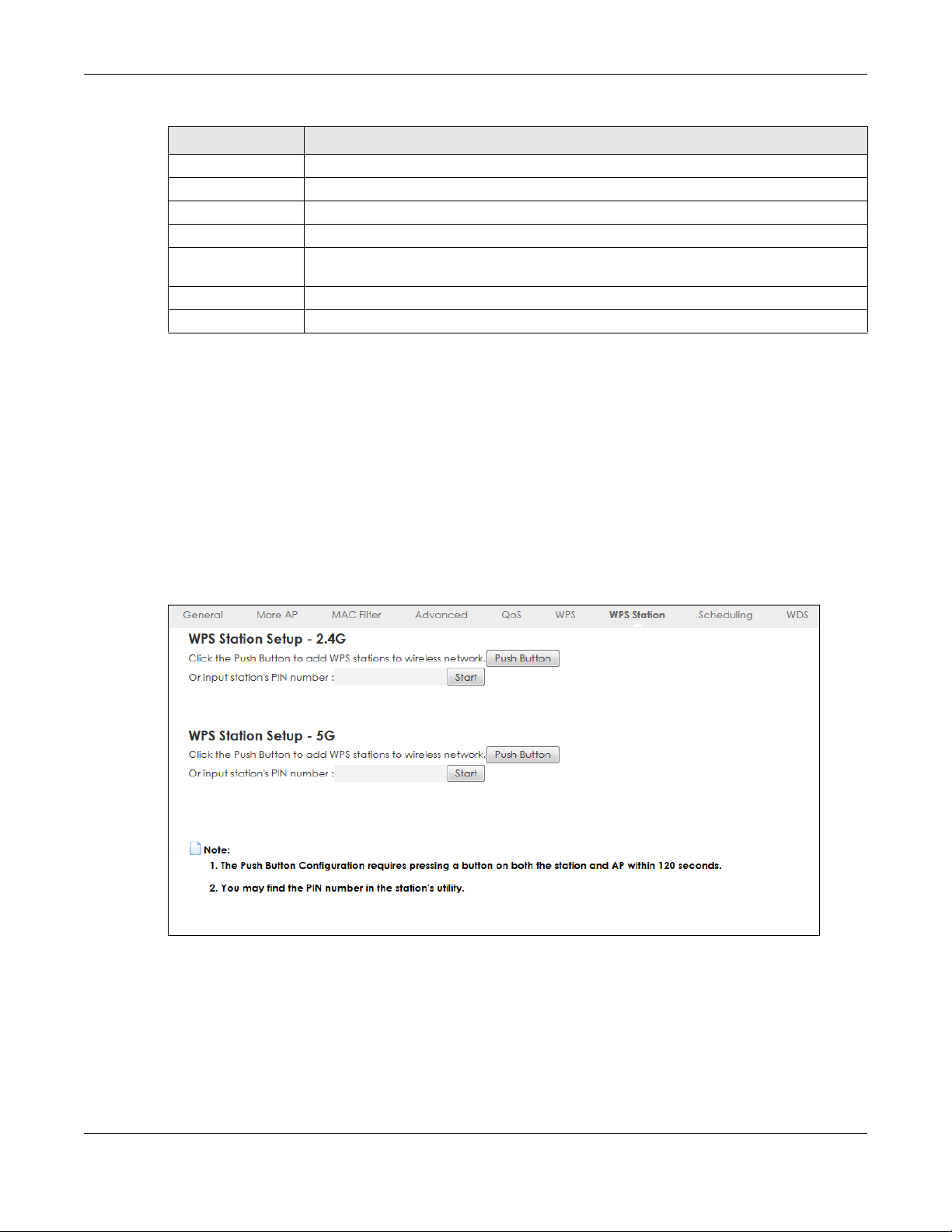
Table 29 Configuration > Network > Wireless LAN > WPS (continued)
LABEL DESCRIPTION
Status This displays Configured when the LTE5366 has configured wireless security settings.
802.11 Mode This is the 802.11 mode used. Only compliant WLAN devices can associate with the LTE5366.
SSID This is the name of the wireless network (the LTE5366’s first SSID).
Security This is the type of wireless security employed by the network.
Release
Configuration
Cancel Click Cancel to reload the previous configuration for this screen.
Apply Click Apply to save your changes back to the LTE5366.
Click this button to remove all configured wireless and wireless security settings for WPS
connections on the LTE5366.
7.9 WPS Station Screen
Use this screen when you want to add a wireless station using WPS. To open this screen, click
Configuration > Network > Wireless LAN > WPS Station tab.
Note: After you click Push Button on this screen, you have to press a similar button in the
wireless station utility within 2 minutes. To add the second wireless station, you have to
press these buttons on both device and the wireless station again after the first 2
minutes.
Chapter 7 Wireless LAN
Figure 48 Configuration > Network > Wireless LAN > WPS Station
LTE5366 Series User’s Guide
83
Page 84
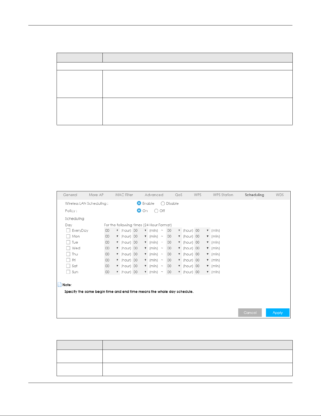
The following table describes the labels in this screen.
Table 30 Configuration > Network > Wireless LAN > WPS Station
LABEL DESCRIPTION
WPS Station Setup - 2.4G / WPS Station Setup - 5G
Push Button Use this button when you use the PBC (Push Button Configuration) method to configure
Or input station’s PIN
number
wireless station’s wireless settings.
Click this to start WPS-aware wireless station scanning and the wireless security information
synchronization.
Use this button when you use the PIN Configuration method to configure wireless station’s
wireless settings.
Type the same PIN number generated in the wireless station’s utility. Then click Start to
associate to each other and perform the wireless security information synchronization.
7.10 Scheduling Screen
Use this screen to set the times your wireless LAN is turned on and off. Wireless LAN scheduling is disabled
by default. The wireless LAN can be scheduled to turn on or off on certain days and at certain times. To
open this screen, click Configuration > Network > Wireless LAN > Scheduling tab.
Chapter 7 Wireless LAN
Figure 49 Configuration > Network > Wireless LAN > Scheduling
The following table describes the labels in this screen.
Table 31 Configuration > Network > Wireless LAN > Scheduling
LABEL DESCRIPTION
Wireless LAN
Scheduling
Policy Select On or Off to specify whether the Wireless LAN is turned on or off. This field works in
Select Enable to activate the wireless LAN scheduling feature. Select Disable to turn it off.
conjunction with the Day and For the following times fields.
LTE5366 Series User’s Guide
84
Page 85
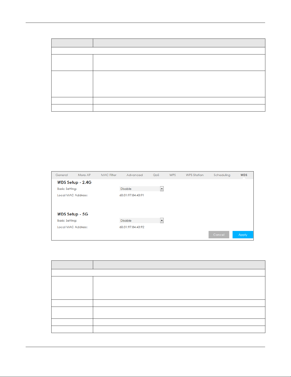
Table 31 Configuration > Network > Wireless LAN > Scheduling (continued)
LABEL DESCRIPTION
Scheduling
Day Select Everyday or the specific days to turn the Wireless LAN on or off. If you select Everyday
For the following
times (24-Hour
Format)
Cancel Click Cancel to reload the previous configuration for this screen.
Apply Click Apply to save your changes back to the LTE5366.
7.11 WDS Screen
A Wireless Distribution System (WDS) is a wireless connection between two or more APs. Use this screen to
configure the LTE5366’s WDS settings. To open this screen, click Configuration > Network > Wireless LAN >
WDS tab.
Chapter 7 Wireless LAN
you can not select any specific days. This field works in conjunction with the For the following
times field.
Select a begin time using the first set of hour and minute (min) drop down boxes and select
an end time using the second set of hour and minute (min) drop down boxes. If you have
chosen On earlier for the WLAN Status the Wireless LAN will turn on between the two times
you enter in these fields. If you have chosen Off earlier for the WLAN Status the Wireless LAN
will turn off between the two times you enter in these fields.
Figure 50 Configuration > Network > Wireless LAN > WDS
The following table describes the labels in this screen.
Table 32 Configuration > Network > Wireless LAN > WDS
LABEL DESCRIPTION
WDS Setup - 2.4G / WDS Setup - 5G
Basic Setting Select Disable to turn off the WDS function on the LTE5366.
Select AP+Bridge to have the LTE5366 function as a bridge and access point simultaneously.
Select Bridge Only to have the LTE5366 act as a wireless bridge only.
Local MAC Address This shows the MAC address of the LTE5366.
Remote MAC
Address
Cancel Click Cancel to reload the previous configuration for this screen.
Apply Click Apply to save your changes back to the LTE5366.
Type the MAC address of the peer device in a valid MAC address format, that is, six
hexadecimal character pairs, for example, 12:34:56:78:9a:bc.
LTE5366 Series User’s Guide
85
Page 86
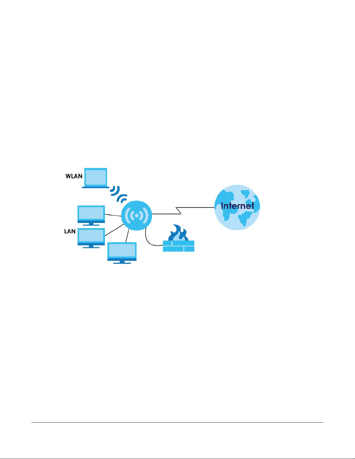
8.1 Overview
This chapter describes how to configure LAN settings.
A Local Area Network (LAN) is a shared communication system to which many computers are
attached. A LAN is a computer network limited to the immediate area, usually the same building or floor
of a building.
Figure 51 LAN Example
CHAPTER 8
LAN
The LAN screens can help you configure a manage IP address, and partition your physical network into
logical networks.
8.2 What You Can Do
• Use the IP screen to change the IP address for your LTE5366 (Section 8.4 on page 87).
8.3 What You Need To Know
The actual physical connection determines whether the LTE5366 ports are LAN or WAN ports. There are
two separate IP networks, one inside the LAN network and the other outside the WAN network as shown
next.
LTE5366 Series User’s Guide
86
Page 87
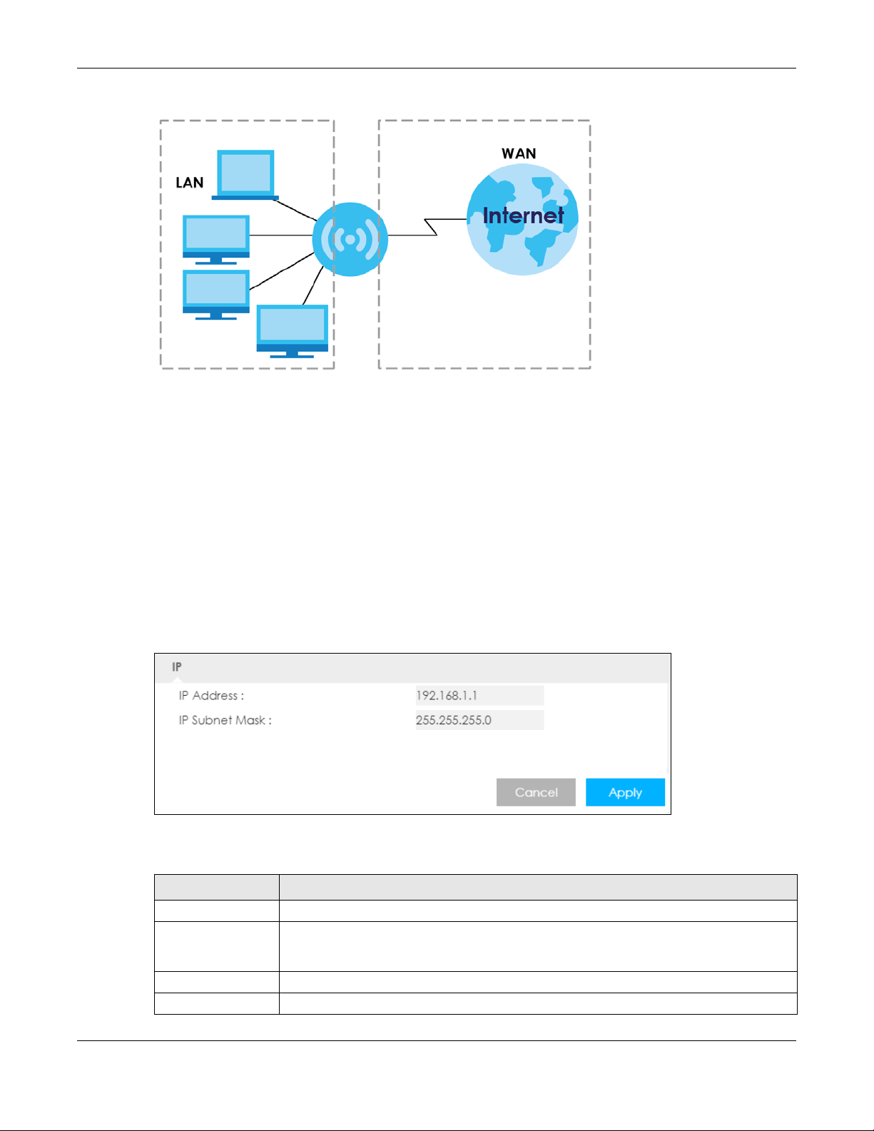
Chapter 8 LAN
Figure 52 LAN and WAN IP Addresses
The LAN parameters of the LTE5366 are preset in the factory with the following values:
• IP address of 192.168.1.1 with subnet mask of 255.255.255.0 (24 bits)
• DHCP server enabled with 32 client IP addresses starting from 192.168.1.33.
These parameters should work for the majority of installations. If your ISP gives you explicit DNS server
address(es), read the embedded Web Configurator help regarding what fields need to be configured.
8.4 LAN IP Screen
Use this screen to change the IP address for your LTE5366. Click Configuration > Network > LAN > IP.
Figure 53 Configuration > Network > LAN > IP
The following table describes the labels in this screen.
Table 33 Configuration > Network > LAN > IP
LABEL DESCRIPTION
IP Address Type the IP address of your LTE5366 in dotted decimal notation.
IP Subnet Mask The subnet mask specifies the network number portion of an IP address. Your LTE5366 will
automatically calculate the subnet mask based on the IP address that you assign. Unless
you are implementing subnetting, use the subnet mask computed by the LTE5366.
Cancel Click Cancel to begin configuring this screen afresh.
Apply Click Apply to save your changes back to the LTE5366.
LTE5366 Series User’s Guide
87
Page 88

9.1 Overview
DHCP (Dynamic Host Configuration Protocol, RFC 2131 and RFC 2132) allows individual clients to obtain
TCP/IP configuration at start-up from a server. You can configure the LTE5366’s LAN as a DHCP server or
disable it. When configured as a server, the LTE5366 provides the TCP/IP configuration for the clients. If
DHCP service is disabled, you must have another DHCP server on your LAN, or else the computer must
be manually configured.
9.1.1 What You Can Do
• Use the General screen to enable the DHCP server (Section 9.2 on page 88).
• Use the Advanced screen to assign IP addresses on the LAN to specific individual computers based
on their MAC Addresses (Section 9.3 on page 90).
• Use the Client List screen to view the current DHCP client information (Section 9.4 on page 92).
CHAPTER 9
DHCP Server
9.1.2 What You Need To Know
The following terms and concepts may help as you read through this chapter.
MAC Addresses
Every Ethernet device has a unique MAC (Media Access Control) address. The MAC address is assigned
at the factory and consists of six pairs of hexadecimal characters, for example, 00:A0:C5:00:00:02. Find
out the MAC addresses of your network devices if you intend to add them to the DHCP Client List screen.
IP Pool Setup
The LTE5366 is pre-configured with a pool of 32 IP addresses starting from 192.168.1.33 to 192.168.1.64. This
configuration leaves 31 IP addresses (excluding the LTE5366 itself) in the lower range (192.168.1.2 to
192.168.1.32) for other server computers, for instance, servers for mail, FTP, TFTP, web, etc., that you may
have.
9.2 DHCP Server General Screen
The LTE5366 has built-in DHCP server capability that assigns IP addresses to systems that support DHCP
client capability. Use this screen to enable the DHCP server. Click Configuration > Network > DHCP
Server. The following screen displays.
LTE5366 Series User’s Guide
88
Page 89
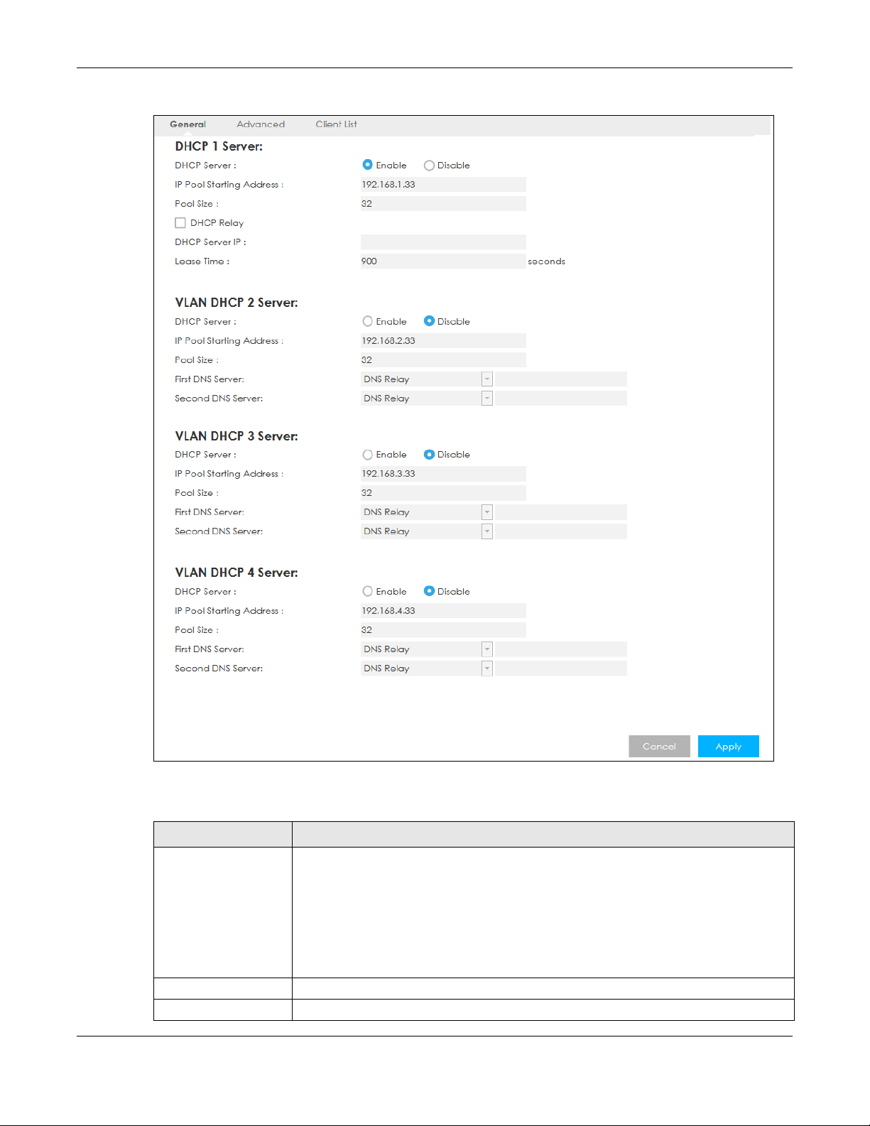
Chapter 9 DHCP Server
Figure 54 Configuration > Network > DHCP Server > General
The following table describes the labels in this screen.
Table 34 Configuration > Network > DHCP Server > General
LABEL DESCRIPTION
DHCP Server Select Enable to activate DHCP for LAN.
DHCP (Dynamic Host Configuration Protocol, RFC 2131 and RFC 2132) allows individual
clients (computers) to obtain TCP/IP configuration at startup from a server. Enable the
DHCP server unless your ISP instructs you to do otherwise. Select Disable to stop the
LTE5366 acting as a DHCP server. When configured as a server, the LTE5366 provides TCP/
IP configuration for the clients. If not, DHCP service is disabled and you must have another
DHCP server on your LAN, or else the computers must be manually configured. When set
as a server, fill in the following four fields.
IP Pool Starting Address This field specifies the first of the contiguous addresses in the IP address pool for LAN.
Pool Size This field specifies the size, or count of the IP address pool for LAN.
LTE5366 Series User’s Guide
89
Page 90

Chapter 9 DHCP Server
Table 34 Configuration > Network > DHCP Server > General (continued)
LABEL DESCRIPTION
DHCP Relay Select this option to have the LTE5366 forward DHCP requests to the DHCP server.
DHCP Server IP This field is configurable only when you select DHCP Relay.
Enter the IP address of the actual remote DHCP server in this field.
Lease Time This is the period of time DHCP-assigned addresses is used. DHCP automatically assigns IP
VLAN DHCP x Server
This section is configurable only when you create a corresponding VLAN group in the Interface Gro up screen.
DHCP Server Select Enable to activate DHCP for the VLAN group.
IP Pool Starting Address Specify the first of the contiguous addresses in the IP address pool for LAN.
Pool Size Specify the size, or count of the IP address pool for LAN.
First DNS Server
Second DNS Server
addresses to clients when they log in. DHCP centralizes IP address management on
central computers that run the DHCP server program. DHCP leases addresses, for a
period of time, which means that past addresses are “recycled” and made available for
future reassignment to other systems.
Specify the IP addresses up to two DNS servers for the DHCP clients to use.
Select Obtained From ISP if your ISP dynamically assigns DNS server information (and the
LTE5366's WAN IP address). The field to the right displays the (read-only) DNS server IP
address that the ISP assigns.
Select User-Defined if you have the IP address of a DNS server. Enter the DNS server's IP
address in the field to the right.
Select DNS Relay to have the LTE5366 act as a DNS proxy. The LTE5366's LAN IP address
displays in the field to the right (read-only). The LTE5366 tells the DHCP clients on the LAN
that the LTE5366 itself is the DNS server. When a computer on the LAN sends a DNS query
to the LTE5366, the LTE5366 forwards the query to the LTE5366's system DNS server
(configured in the WAN screen) and relays the response back to the computer.
Cancel Click Cancel to begin configuring this screen afresh.
Apply Click Apply to save your changes back to the LTE5366.
9.3 DHCP Server Advanced Screen
This screen allows you to assign IP addresses on the LAN to specific individual computers based on their
MAC addresses. You can also use this screen to configure the DNS server information that the LTE5366
sends to the DHCP clients.
To change your LTE5366’s static DHCP settings, click Configuration > Network > DHCP Server >
Advanced. The following screen displays.
LTE5366 Series User’s Guide
90
Page 91

Chapter 9 DHCP Server
Figure 55 Configuration > Network > DHCP Server > Advanced
The following table describes the labels in this screen.
Table 35 Configuration > Network > DHCP Server > Advanced
LABEL DESCRIPTION
Static DHCP Table
# This is the index number of the static IP table entry (row).
MAC Address Type the MAC address (with colons) of a computer on your LAN.
IP Address Type the LAN IP address of a computer on your LAN.
DNS Server
DNS Servers
Assigned by DHCP
Server
First DNS Server
Second DNS Server
Cancel Click Cancel to begin configuring this screen afresh.
Apply Click Apply to save your changes back to the LTE5366.
The LTE5366 passes a DNS (Domain Name System) server IP address (in the order you specify
here) to the DHCP clients. The LTE5366 only passes this information to the LAN DHCP clients
when you enable DHCP Server in the General screen. When you disable DHCP Server, DHCP
service is disabled and you must have another DHCP sever on your LAN, or else the
computers must have their DNS server addresses manually configured.
Select User-Defined if you have the IP address of a DNS server. Enter the DNS server's IP
address in the field to the right.
Select DNS Relay to have the LTE5366 act as a DNS proxy. The LTE5366's LAN IP address
displays in the field to the right (read-only). The LTE5366 tells the DHCP clients on the LAN that
the LTE5366 itself is the DNS server. When a computer on the LAN sends a DNS query to the
LTE5366, the LTE5366 forwards the query to the LTE5366's system DNS server (configured in the
WAN screen) and relays the response back to the computer.
LTE5366 Series User’s Guide
91
Page 92
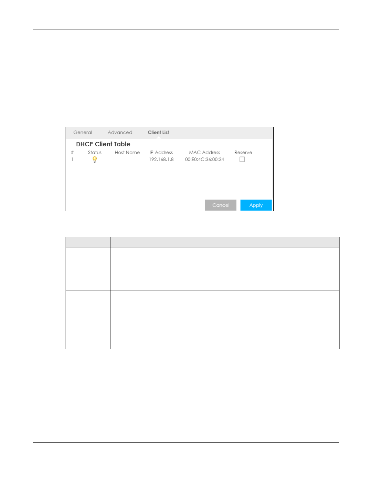
Chapter 9 DHCP Server
9.4 DHCP Client List Screen
The DHCP table shows current DHCP client information (including IP Address, Host Name and MAC
Address) of network clients using the LTE5366’s DHCP servers.
Configure this screen to always assign an IP address to a MAC address (and host name). Click
Configuration > Network > DHCP Server > Client List.
Note: You can also view a read-only client list by clicking Monitor > DHCP Server.
Figure 56 Configuration > Network > DHCP Server > Client List
The following table describes the labels in this screen.
Table 36 Configuration > Network > DHCP Server > Client List
LABEL DESCRIPTION
# This is the index number of the host computer.
Status This field displays whether the connection to the host computer is up (a yellow bulb) or down (a
gray bulb).
Host Name This field displays the computer host name.
IP Address This field displays the IP address relative to the # field listed above.
MAC Address This field shows the MAC address of the computer with the name in the Ho st Nam e field.
Every Ethernet device has a unique MAC (Media Access Control) address which uniquely
identifies a device. The MAC address is assigned at the factory and consists of six pairs of
hexadecimal characters, for example, 00:A0:C5:00:00:02.
Reserve Select this if you want to reserve the IP address for this specific MAC address.
Cancel Click Cancel to reload the previous configuration for this screen.
Apply Click Apply to save your changes back to the LTE5366.
LTE5366 Series User’s Guide
92
Page 93

10.1 Overview
NAT (Network Address Translation - NAT, RFC 1631) is the translation of the IP address of a host in a
packet. For example, the source address of an outgoing packet, used within one network is changed to
a different IP address known within another network.
The figure below is a simple illustration of a NAT network. You want to assign ports 21-25 to one FTP, Telnet
and SMTP server (A in the example), port 80 to another (B in the example) and assign a default server IP
address of 192.168.1.35 to a third (C in the example).
You assign the LAN IP addresses to the devices (A to D) connected to your LTE5366. The ISP assigns the
WAN IP address. The NAT network appears as a single host on the Internet. All traffic coming from A to D
going out to the Internet use the IP address of the LTE5366, which is 192.168.1.1.
Figure 57 NAT Example
CHAPTER 10
NAT
Note: You must create a firewall rule in addition to setting up NAT, to allow traffic from the
WAN to be forwarded through the LTE5366.
10.1.1 What You Can Do
• Use the General screen to enable NAT (Section 10.2 on page 94).
• Use the Port Forwarding screen to set a default server and change your LTE5366’s port forwarding
settings to forward incoming service requests to the server(s) on your local network (Section 10.3 on
page 94).
LTE5366 Series User’s Guide
93
Page 94

• Use the Port Trigger screen to change your LTE5366’s trigger port settings (Section 10.4 on page 98).
• Use the ALG screen to enable or disable SIP (VoIP) ALG (Application Layer Gateway) in the LTE5366
(Section 10.5 on page 99).
10.2 General Screen
Use this screen to enable NAT and set a default server. Click Configuration > Network > NAT to open the
General screen.
Figure 58 Configuration > Network > NAT > General
Chapter 10 NAT
The following table describes the labels in this screen.
Table 37 Configuration > Network > NAT > General
LABEL DESCRIPTION
Network Address
Translation (NAT)
NAT Loopback NAT loopback allows local users to use a domain name to access a server on the local
Cancel Click Cancel to begin configuring this screen afresh.
Apply Click Apply to save your changes back to the LTE5366.
Network Address Translation (NAT) allows the translation of an Internet protocol address
used within one network (for example a private IP address used in a local network) to a
different IP address known within another network (for example a public IP address used on
the Internet).
Select Enable to activate NAT. Select Disable to turn it off.
network. A packet sent to the public (WAN) IP address is always forwarded to the default
gateway (the LTE5366). With NAT loopback enabled, the LTE5366 uses the WAN interface’s
IP address as the packet’s source address and treats the packet as if it came from the WAN
interface. The packet then can be forwarded to the local server according to the port
forwarding rule.
Select Enable to activate NAT loopback. Select Disable to turn it off.
10.3 Port Forwarding Screen
Use this screen to forward incoming service requests to the server(s) on your local network and set a
default server. You may enter a single port number or a range of port numbers to be forwarded, and the
local IP address of the desired server. The port number identifies a service; for example, web service is on
LTE5366 Series User’s Guide
94
Page 95

Chapter 10 NAT
port 80 and FTP on port 21. In some cases, such as for unknown services or where one server can support
more than one service (for example both FTP and web service), it might be better to specify a range of
port numbers.
In addition to the servers for specified services, NAT supports a default server. A service request that does
not have a server explicitly designated for it is forwarded to the default server. If the default is not
defined, the service request is simply discarded.
Note: Many residential broadband ISP accounts do not allow you to run any server processes
(such as a Web or FTP server) from your location. Your ISP may periodically check for
servers and may suspend your account if it discovers any active services at your
location. If you are unsure, refer to your ISP.
Port forwarding allows you to define the local servers to which the incoming services will be forwarded.
To change your LTE5366’s port forwarding settings, click Configuration > Network > NAT > Port
Forwarding. The screen appears as shown.
Note: If you do not assign a Default Server, the LTE5366 discards all packets received for ports
that are not specified in this screen or remote management.
Refer to Appendix D on page 215 for port numbers commonly used for particular services.
Figure 59 Configuration > Network > NAT > Port Forwarding
LTE5366 Series User’s Guide
95
Page 96

Chapter 10 NAT
The following table describes the labels in this screen.
Table 38 Configuration > Network > NAT > Port Forwarding
LABEL DESCRIPTION
Default Server Setup
Default Server In addition to the servers for specified services, NAT supports a default server. A default
Change to Server Select this and manually enter the server’s IP address.
Service Name Select a pre-defined service from the drop-down list box. The pre-defined service port
Service Protocol Select the transport layer protocol supported by this virtual server. Choices are TCP, UDP, or
WAN Interface Select the WAN interface on which the matched packets are received.
Port Range Specify the first and last external port numbers that identify the service.
Translation Port
Range
Server IP Address Enter the inside IP address of the virtual server here and click Add to add it in the port
# This is the number of an individual port forwarding server entry.
Status This icon is turned on when the rule is enabled.
Name This field displays a name to identify this rule.
Protocol This is the transport layer protocol used for the service.
WAN Interface This field displays the WAN interface on which the matched packets are received.
Port This field displays the port number(s).
Translation Port This field displays the internal port number(s) that identifies the service.
Server IP Address This field displays the inside IP address of the server.
Modify Click the Edit icon to open the edit screen where you can modify an existing rule.
Cancel Click Cancel to begin configuring this screen afresh.
Apply Click Apply to save your changes back to the LTE5366.
server receives packets from ports that are not specified in the Port Forwarding screen. You
can decide whether you want to use the default server or specify a server manually.
Select this to use the default server.
number(s) and protocol will be displayed in the port forwarding summary table.
Otherwise, select User define to manually enter the service name and port number(s) and
select the IP protocol.
TCP_UDP.
If you have chosen a pre-defined service in the Service Name field, the protocol will be
configured automatically.
If you have chosen a pre-defined service in the Service Name field, the port number(s) will
be configured automatically.
Specify the first and last internal port numbers that identify the service.
If you have chosen a pre-defined service in the Service Name field, the port number(s) will
be configured automatically.
forwarding summary table.
Click the Delete icon to remove a rule.
10.3.1 Port Forwarding Edit Screen
This screen lets you edit a port forwarding rule. Click a rule’s Edit icon in the Port Forwarding screen to
open the following screen.
LTE5366 Series User’s Guide
96
Page 97
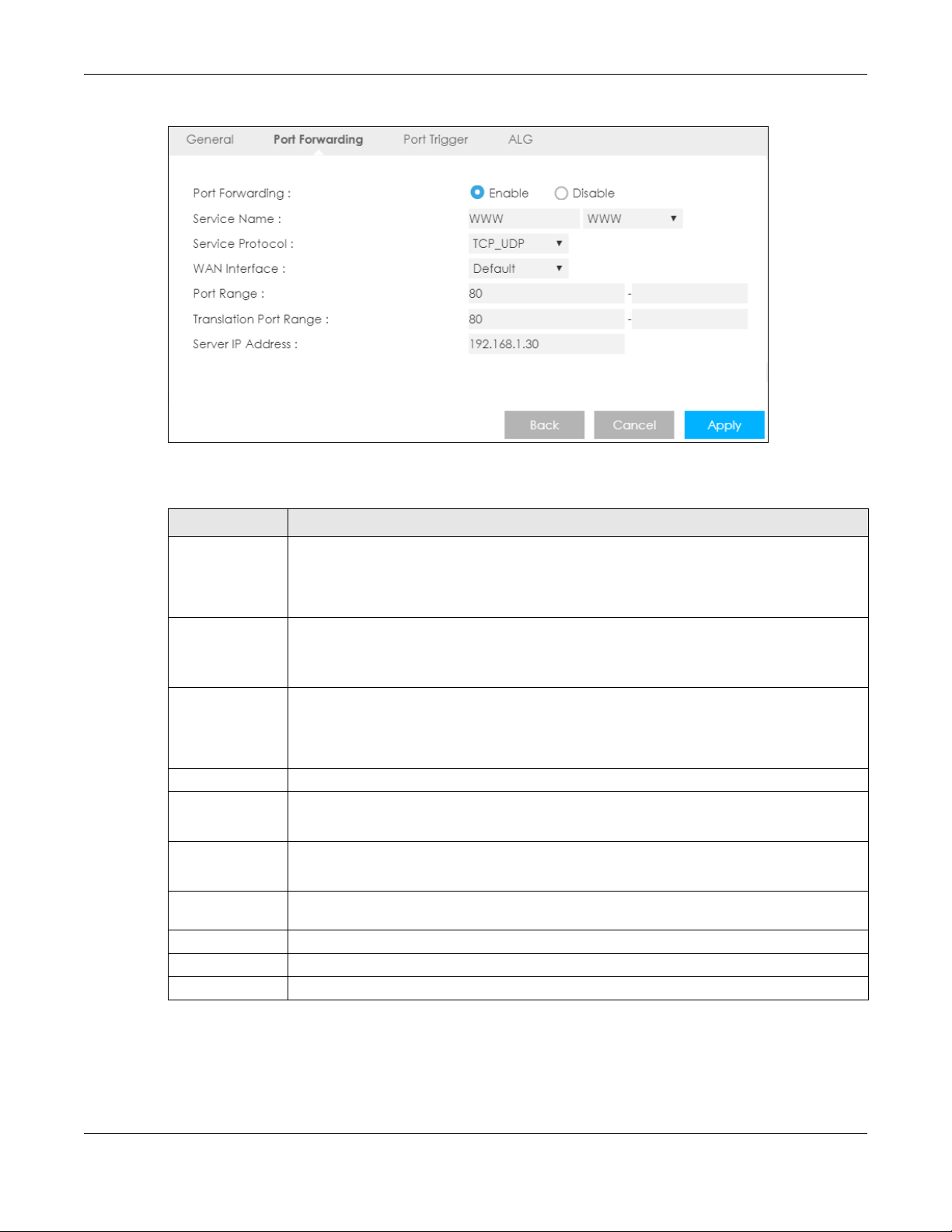
Chapter 10 NAT
Figure 60 Configuration > Network > NAT > Port Forwarding Edit
The following table describes the labels in this screen.
Table 39 Configuration > Network > NAT > Port Forwarding Edit
LABEL DESCRIPTION
Port Forwarding Select Enable to turn on this rule and the requested service can be forwarded to the host with
a specified internal IP address.
Select Disable to disallow forwarding of these ports to an inside server without having to delete
the entry.
Service Name Select User define and type a name (of up to 31 printable characters) to identify this rule in the
first field next to Service Name. Otherwise, select a predefined service in the second field next
to Service Name. The predefined service name and port number(s) will display in the Service
Name and Port Range fields.
Service Protocol Select the transport layer protocol supported by this virtual server. Choices are TCP, UDP, or
TCP_UDP.
If you have chosen a pre-defined service in the Service Name field, the protocol will be
configured automatically.
WAN Interface Select the WAN interface on which the matched packets are received.
Port Range Type a port number(s) to define the service to be forwarded to the specified server.
To specify a range of ports, enter the first number and the last number of the range.
Translation Port
Range
Server IP Address Type the IP address of the server on your LAN that receives packets from the port(s) specified in
Back Click Back to return to the previous screen.
Cancel Click Cancel to begin configuring this screen afresh.
Apply Click Apply to save your changes back to the LTE5366.
Enter a port number to which you want the incoming ports translated.
For a range of ports, enter the first number and the last number of the range.
the Port Range field.
LTE5366 Series User’s Guide
97
Page 98
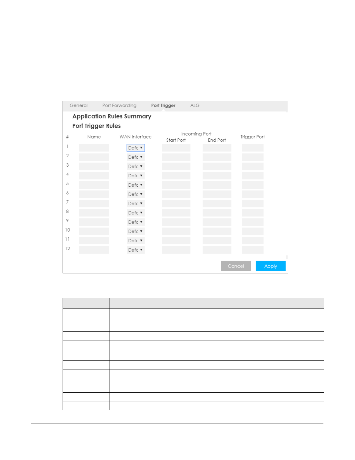
10.4 Port Trigger Screen
To change your LTE5366’s trigger port settings, click Configuration > Network > NAT > Port Trigger. The
screen appears as shown.
Note: Only one LAN computer can use a trigger port (range) at a time.
Figure 61 Configuration > Network > NAT > Port Trigger
Chapter 10 NAT
The following table describes the labels in this screen.
Table 40 Configuration > Network > NAT > Port Trigger
LABEL DESCRIPTION
# This is the rule index number (read-only).
Name Type a unique name (up to 15 characters) for identification purposes. All characters are
permitted - including spaces.
WAN Interface Select the WAN interface through which the matched packets are transmitted.
Incoming Port Incoming Port is a port (or a range of ports) that a server on the WAN uses when it sends out a
Start Port Type a port number or the starting port number in a range of port numbers.
End Port Type a port number or the ending port number in a range of port numbers.
Trigger Port The trigger port is a port that causes (or triggers) the LTE5366 to record the IP address of the
Cancel Click Cancel to begin configuring this screen afresh.
Apply Click Apply to save your changes back to the LTE5366.
particular service. The LTE5366 forwards the traffic with this port (or range of ports) to the client
computer on the LAN that requested the service.
LAN computer that sent the traffic to a server on the WAN.
LTE5366 Series User’s Guide
98
Page 99
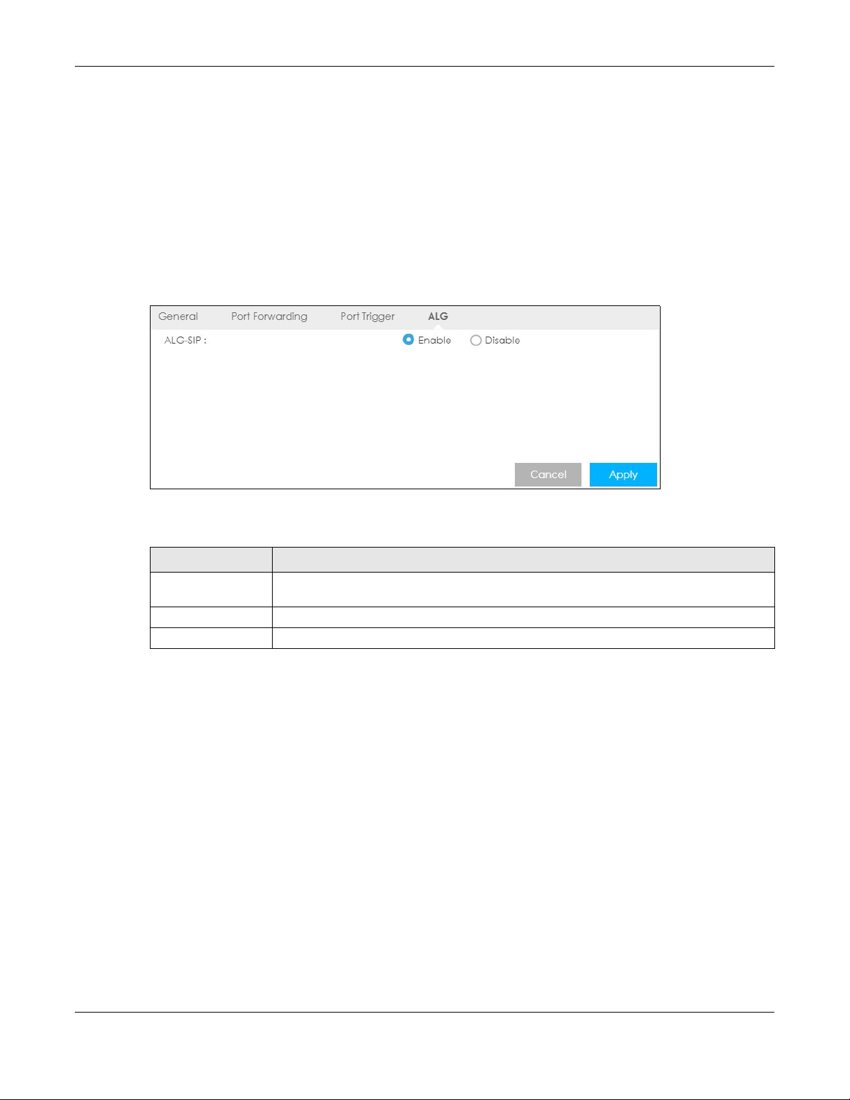
10.5 ALG Screen
Some NAT routers may include a SIP Application Layer Gateway (ALG). A SIP ALG allows SIP calls to pass
through NAT by examining and translating IP addresses embedded in the data stream. When the
LTE5366 registers with the SIP register server, the SIP ALG translates the LTE5366’s private IP address inside
the SIP data stream to a public IP address. You do not need to use STUN or an outbound proxy if your
LTE5366 is behind a SIP ALG
To enable and disable the SIP ALG in the LTE5366, click Configuration > Network > NAT > ALG. The screen
appears as shown.
Figure 62 Configuration > Network > NAT > ALG
Chapter 10 NAT
The following table describes the labels in this screen.
Table 41 Configuration > Network > NAT > ALG
LABEL DESCRIPTION
ALG-SIP Select Enable to make sure SIP (VoIP) works correctly with port-forwarding and address-
mapping rules. Otherwise, select Disable to turn off the SIP ALG.
Apply Click Apply to save your changes back to the LTE5366.
Cancel Click Cancel to begin configuring this screen afresh.
10.6 Technical Reference
The following section contains additional technical information about the LTE5366 features described in
this chapter.
10.6.1 NAT Port Forwarding: Services and Port Numbers
A port forwarding set is a list of inside (behind NAT on the LAN) servers, for example, web or FTP, that you
can make accessible to the outside world even though NAT makes your whole inside network appear
as a single machine to the outside world.
Use the Port Forwarding screen to forward incoming service requests to the server(s) on your local
network. You may enter a single port number or a range of port numbers to be forwarded, and the local
IP address of the desired server. The port number identifies a service; for example, web service is on port
80 and FTP on port 21. In some cases, such as for unknown services or where one server can support
LTE5366 Series User’s Guide
99
Page 100

Chapter 10 NAT
more than one service (for example both FTP and web service), it might be better to specify a range of
port numbers.
In addition to the servers for specified services, NAT supports a default server. A service request that does
not have a server explicitly designated for it is forwarded to the default server. If the default is not
defined, the service request is simply discarded.
Note: Many residential broadband ISP accounts do not allow you to run any server processes
(such as a Web or FTP server) from your location. Your ISP may periodically check for
servers and may suspend your account if it discovers any active services at your
location. If you are unsure, refer to your ISP.
10.6.2 NAT Port Forwarding Example
Let's say you want to assign ports 21-25 to one FTP, Telnet and SMTP server (A in the example), port 80 to
another (B in the example) and assign a default server IP address of 192.168.1.35 to a third (C in the
example). You assign the LAN IP addresses and the ISP assigns the WAN IP address. The NAT network
appears as a single host on the Internet.
Figure 63 Multiple Servers Behind NAT Example
10.6.3 Trigger Port Forwarding
Some services use a dedicated range of ports on the client side and a dedicated range of ports on the
server side. With regular port forwarding you set a forwarding port in NAT to forward a service (coming in
from the server on the WAN) to the IP address of a computer on the client side (LAN). The problem is that
port forwarding only forwards a service to a single LAN IP address. In order to use the same service on a
different LAN computer, you have to manually replace the LAN computer's IP address in the forwarding
port with another LAN computer's IP address.
Trigger port forwarding solves this problem by allowing computers on the LAN to dynamically take turns
using the service. The LTE5366 records the IP address of a LAN computer that sends traffic to the WAN to
request a service with a specific port number and protocol (a "trigger" port). When the LTE5366's WAN
port receives a response with a specific port number and protocol ("incoming" port), the LTE5366
forwards the traffic to the LAN IP address of the computer that sent the request. After that computer’s
connection for that service closes, another computer on the LAN can use the service in the same
LTE5366 Series User’s Guide
100
 Loading...