

Default Login Details
User’s Guide
GS1900 Series
GbE Smart Managed Switch
IP Address http://192.168.1.1 (In-band ports)
User Name admin
Password 1234
Version 2.60 Edition 1, 02/2020
Copyright © 2020 Zyxel Communications Corporation

IMPORTANT!
READ CAREFULLY BEFORE USE.
KEEP THIS GUIDE FOR FUTURE REFERENCE.
Screenshots and graphics in this book may differ slightly from your product due to differences in your
product firmware or your computer operating system. Every effort has been made to ensure that the
information in this manual is accurate.
Note: This guide is a reference for a series of products. Therefore some features or options in
this guide may not be available in your product.
Note: It is recommended you use the Web Configurator to configure the Switch.
Related Documentation
• Online Help
Click the help link for a description of the fields in the Switch menus.
•More Information
Go to https://businessforum.zyxel.com for product discussions.
•Go to support.zyxel.com to find other information on the Switch
.
GS1900 Series User’s Guide
2
Document Conventions
Warnings and Notes
These are how warnings and notes are shown in this guide.
Warnings tell you about things that could harm you or your device.
Note: Notes tell you other important information (for example, other things you may need to
configure or helpful tips) or recommendations.
Syntax Conventions
• All models may be referred to as the “Switch” in this guide.
• Product labels, screen names, field labels and field choices are all in bold font.
• A right angle bracket ( > ) within a screen name denotes a mouse click. For example, Configuration >
System > Information means you first click Configuration in the navigation panel, then the System sub
menu and finally the Information tab to get to that screen.
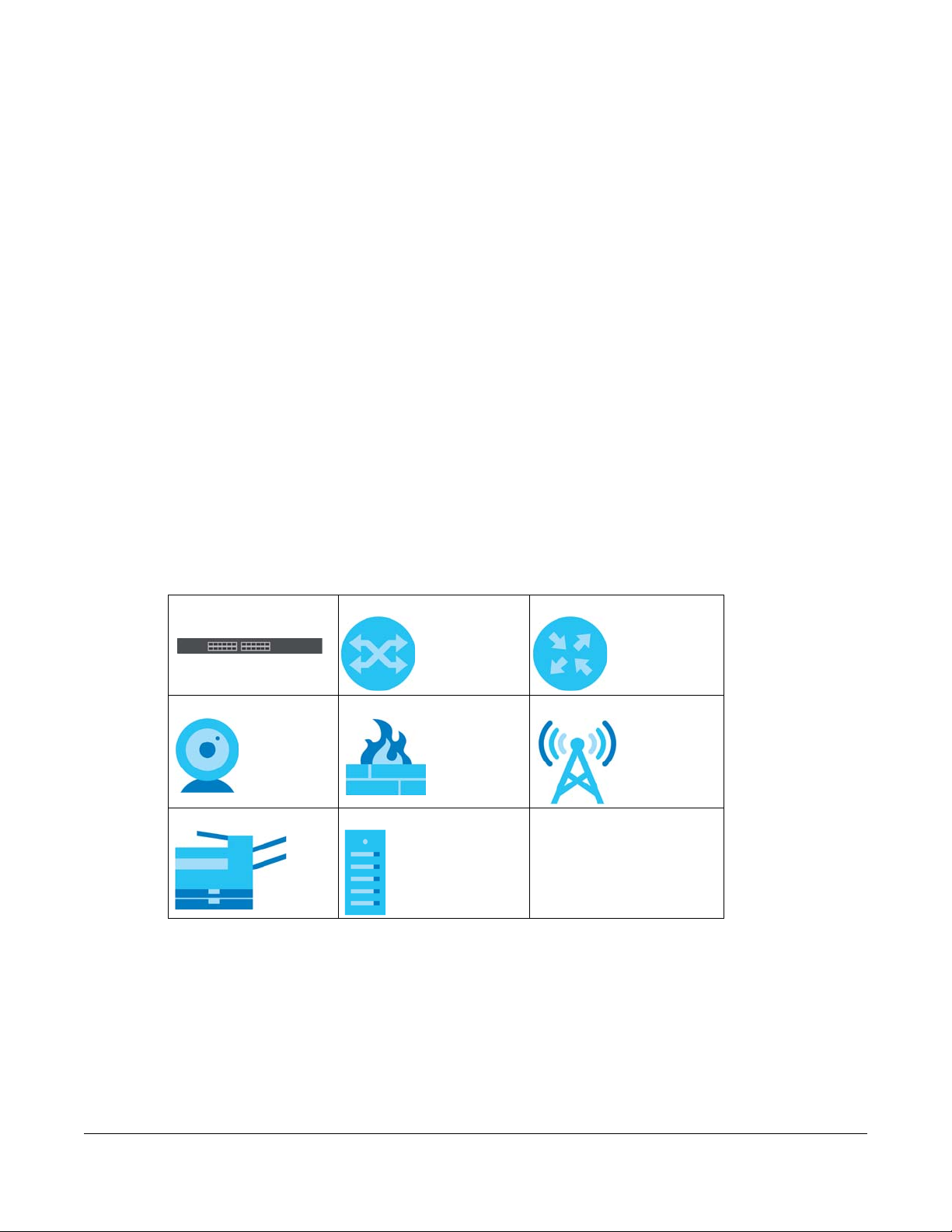
Icons Used in Figures
Figures in this user guide may use the following generic icons. The Switch icon is not an exact
representation of your device.
Switch Generic Switch Generic Router
IP Camera Firewall Cell Tower
Printer Server
GS1900 Series User’s Guide
3

Contents Overview
Contents Overview
User’s Guide ......................................................................................................................................16
Getting to Know Your Switch .............................................................................................................. 17
Hardware Installation and Connection ............................................................................................. 22
Hardware Overview ............................................................................................................................. 28
ZON Utility ............................................................................................................................................... 38
Web Configurator ................................................................................................................................. 43
Getting Start .......................................................................................................................................... 52
Technical Reference ........................................................................................................................61
Monitor: System ..................................................................................................................................... 62
Monitor: Port .......................................................................................................................................... 65
Monitor: VLAN ....................................................................................................................................... 74
Monitor: MAC Table ............................................................................................................................. 80
Monitor: Link Aggregation ................................................................................................................... 83
Monitor: Loop Guard ........................................................................................................................... 85
Monitor: Multicast ................................................................................................................................. 88
Monitor: Spanning Tree ........................................................................................................................ 92
Monitor: LLDP ......................................................................................................................................... 98
Monitor: Security ................................................................................................................................. 102
Monitor: Management ...................................................................................................................... 105
Configuration: System ........................................................................................................................ 108
Configuration: Port ............................................................................................................................. 113
Configuration: VLAN .......................................................................................................................... 126
Configuration: MAC Table ................................................................................................................ 138
Configuration: Link Aggregation ...................................................................................................... 142
Configuration: Loop Guard ............................................................................................................... 148
Configuration: Mirror .......................................................................................................................... 151
Configuration: Time Range Group ................................................................................................... 154
Configuration: Multicast .................................................................................................................... 159
Configuration: Spanning Tree ........................................................................................................... 167
Configuration: LLDP ............................................................................................................................ 176
Configuration: QoS ............................................................................................................................. 188
Configuration: Security ...................................................................................................................... 197
Configuration: AAA ............................................................................................................................ 207
Configuration: Management ............................................................................................................ 212
Maintenance ...................................................................................................................................... 229
Troubleshooting .................................................................................................................................. 241
GS1900 Series User’s Guide
4

Table of Contents
Table of Contents
Document Conventions .................................................................. ....................................................3
Contents Overview .............................................................................................................................4
Table of Contents.................................................................................................................................5
Part I: User’s Guide.......................................................................................... 16
Chapter 1
Getting to Know Your Switch ............................................................................................................17
1.1 Introduction ..................................................................................................................................... 17
1.2 Example Applications .................................................................................................................... 17
1.2.1 PoE Example Application ..................................................................................................... 17
1.2.2 Backbone Example Application ......................................................................................... 18
1.2.3 Bridging / Fiber Uplink Example Application ...................................................................... 18
1.2.4 Gigabit Ethernet to the Desktop ......................................................................................... 19
1.2.5 IEEE 802.1Q VLAN Application Example ............................................................................. 19
1.2.6 IPv6 Support ........................................................................................................................... 20
1.3 Ways to Manage the Switch ......................................................................................................... 20
1.4 Good Habits for Managing the Switch ........................................................................................21
Chapter 2
Hardware Installation and Connection ...........................................................................................22
2.1 Installation Scenarios ...................................................................................................................... 22
2.2 Desktop Installation Procedure ..................................................................................................... 22
2.3 Wall Mounting ................................................................................................................................. 23
2.3.1 Wall-mounted Installation Requirement ............................................................................. 23
2.4 Rack Mounting ................................................................................................................................ 25
2.4.1 Rack-mounted Installation Requirements .......................................................................... 25
2.4.2 Attaching the Mounting Brackets to the Switch ............................................................... 25
2.4.3 Mounting the Switch on a Rack .......................................................................................... 26
Chapter 3
Hardware Overview...........................................................................................................................28
3.1 Front Panel Connections ............................................................................................................... 28
3.1.1 Ethernet Ports ......................................................................................................................... 29
3.1.2 SFP Slots .................................................................................................................................. 30
3.1.3 PoE Mode (GS1900-48HP and GS1900-48HPv2 only) ........................................................ 31
GS1900 Series User’s Guide
5

Table of Contents
3.2 Rear Panel ....................................................................................................................................... 31
3.2.1 Grounding .............................................................................................................................. 33
3.2.2 Power Connection ................................................................................................................ 34
3.3 LEDs .................................................................................................................................................. 35
3.4 Resetting the Switch (all models except GS1900-24EP/GS1900-24HPv2/GS1900-48HPv2) .... 36
3.5 Resetting the Switch (GS1900-24EP/GS1900-24HPv2/GS1900-48HPv2 only) ............................ 37
3.5.1 Restore Button ....................................................................................................................... 37
3.5.2 Reboot the Switch ................................................................................................................ 37
Chapter 4
ZON Utility ...........................................................................................................................................38
4.1 Zyxel One Network (ZON) Utility Screen ....................................................................................... 38
4.1.1 Requirements ......................................................................................................................... 38
4.1.2 Run the ZON Utility ................................................................................................................. 39
Chapter 5
Web Configurator...............................................................................................................................43
5.1 Overview ......................................................................................................................................... 43
5.2 Access .............................................................................................................................................. 43
5.3 Navigating the Web Configurator ............................................................................................... 45
5.3.1 Title Bar ................................................................................................................................... 45
5.3.2 Navigation Panel .................................................................................................................. 46
Chapter 6
Getting Start........................................................................................................................................52
6.1 Overview ......................................................................................................................................... 52
6.1.1 What You Can Do in this Chapter ....................................................................................... 52
6.2 Getting Start .................................................................................................................................... 52
6.2.1 Wizard ..................................................................................................................................... 53
Part II: Technical Reference........................................................................... 61
Chapter 7
Monitor: System..................................................................................................................................62
7.1 Overview ......................................................................................................................................... 62
7.1.1 What You Can Do in this Chapter ....................................................................................... 62
7.2 IP ....................................................................................................................................................... 62
7.2.1 IPv4 .......................................................................................................................................... 62
7.2.2 IPv6 .......................................................................................................................................... 63
7.3 Information ...................................................................................................................................... 63
GS1900 Series User’s Guide
6

Table of Contents
Chapter 8
Monitor: Port .......................................................................................................................................65
8.1 Overview ......................................................................................................................................... 65
8.1.1 What You Can Do in this Chapter ....................................................................................... 65
8.2 Port ................................................................................................................................................... 65
8.2.1 Status ...................................................................................................................................... 65
8.2.2 Port Counters ......................................................................................................................... 66
8.2.3 Bandwidth Utilization ............................................................................................................ 68
8.3 PoE .................................................................................................................................................... 69
8.4 Bandwidth Management .............................................................................................................. 71
8.4.1 Bandwidth Control ................................................................................................................ 71
8.5 Storm Control .................................................................................................................................. 72
Chapter 9
Monitor: VLAN.....................................................................................................................................74
9.1 Overview ......................................................................................................................................... 74
9.1.1 What You Can Do in this Chapter ....................................................................................... 74
9.2 VLAN ................................................................................................................................................ 74
9.2.1 VLAN ....................................................................................................................................... 74
9.2.2 Port .......................................................................................................................................... 75
9.2.3 VLAN Port ............................................................................................................................... 76
9.3 Guest VLAN ..................................................................................................................................... 77
9.4 Voice VLAN ..................................................................................................................................... 78
Chapter 10
Monitor: MAC Table...........................................................................................................................80
10.1 Overview ....................................................................................................................................... 80
10.1.1 What You Can Do in this Chapter ..................................................................................... 81
10.2 MAC Table ..................................................................................................................................... 81
Chapter 11
Monitor: Link Aggregation ................................................................................................................83
11.1 Overview ....................................................................................................................................... 83
11.1.1 What You Can Do in this Chapter ..................................................................................... 83
11.2 Link Aggregation .......................................................................................................................... 83
Chapter 12
Monitor: Loop Guard .........................................................................................................................85
12.1 Overview ....................................................................................................................................... 85
12.1.1 What You Can Do in this Chapter ..................................................................................... 86
12.2 Loop Guard ................................................................................................................................... 86
GS1900 Series User’s Guide
7

Table of Contents
Chapter 13
Monitor: Multicast...............................................................................................................................88
13.1 Overview ....................................................................................................................................... 88
13.1.1 What You Can Do in this Chapter ..................................................................................... 88
13.2 IGMP ............................................................................................................................................... 88
13.2.1 VLAN ..................................................................................................................................... 88
13.2.2 Statistics ................................................................................................................................ 89
13.2.3 Group ................................................................................................................................... 90
13.2.4 Router ................................................................................................................................... 91
Chapter 14
Monitor: Spanning Tree......................................................................................................................92
14.1 Overview ....................................................................................................................................... 92
14.1.1 What You Can Do in this Chapter ..................................................................................... 92
14.2 Spanning Tree ............................................................................................................................... 92
14.2.1 CIST ....................................................................................................................................... 92
14.2.2 CIST Port ................................................................................................................................ 93
14.2.3 MST ........................................................................................................................................ 94
14.2.4 MST Port ................................................................................................................................ 95
14.2.5 STP Statistics .......................................................................................................................... 96
Chapter 15
Monitor: LLDP ......................................................................................................................................98
15.1 Overview ....................................................................................................................................... 98
15.1.1 What You Can Do in this Chapter ..................................................................................... 98
15.2 LLDP ................................................................................................................................................ 98
15.2.1 Statistics ................................................................................................................................ 98
15.2.2 Remote Information ............................................................................................................ 99
15.2.3 Overloading ....................................................................................................................... 100
Chapter 16
Monitor: Security ..............................................................................................................................102
16.1 Overview ..................................................................................................................................... 102
16.1.1 What You Can Do in this Chapter ................................................................................... 102
16.2 Port Security ................................................................................................................................. 102
16.3 802.1X ........................................................................................................................................... 103
16.3.1 Port ...................................................................................................................................... 103
16.3.2 Authenticated Hosts ......................................................................................................... 104
Chapter 17
Monitor: Management ....................................................................................................................105
17.1 Overview ..................................................................................................................................... 105
17.1.1 What You Can Do in this Chapter ................................................................................... 105
GS1900 Series User’s Guide
8

Table of Contents
17.2 Syslog ........................................................................................................................................... 105
17.3 Error Disable ................................................................................................................................. 106
Chapter 18
Configuration: System ..................................................................... ... .... .... .....................................108
18.1 Overview ..................................................................................................................................... 108
18.1.1 What You Can Do in this Chapter ................................................................................... 108
18.2 IP ................................................................................................................................................... 108
18.2.1 The IPv4 Screen ................................................................................................................. 108
18.2.2 The IPv6 Screen ................................................................................................................. 109
18.3 Time .............................................................................................................................................. 110
18.3.1 The System Time Screen ................................................................................................... 110
18.3.2 The SNTP Server Screen .................................................................................................... 111
18.4 Information .................................................................................................................................. 111
18.4.1 The System Information Screen ....................................................................................... 111
Chapter 19
Configuration: Port............................................. .... .... ............................................ .... ... ...................113
19.1 Overview ..................................................................................................................................... 113
19.1.1 What You Can Do in this Chapter ................................................................................... 113
19.2 Port ............................................................................................................................................... 113
19.2.1 The Port Screen ................................................................................................................. 113
19.2.2 The Port Edit Screen .......................................................................................................... 114
19.3 EEE ................................................................................................................................................ 115
19.3.1 The EEE Screen .................................................................................................................. 115
19.3.2 The EEE Edit Screen ........................................................................................................... 116
19.4 PoE ................................................................................................................................................ 117
19.4.1 The Global Screen ............................................................................................................ 117
19.4.2 The Port Screen ................................................................................................................. 118
19.4.3 The PoE Edit Screen .......................................................................................................... 120
19.5 Bandwidth Management .......................................................................................................... 122
19.5.1 The Bandwidth Control Screen ........................................................................................ 122
19.5.2 The Port Rate Edit Screen ................................................................................................. 123
19.6 Storm Control .............................................................................................................................. 123
19.6.1 The Port Screen ................................................................................................................. 124
19.6.2 The Port Edit Screen .......................................................................................................... 124
Chapter 20
Configuration: VLAN................. ... .... .... ... ............................................ .... .... .....................................126
20.1 Overview ..................................................................................................................................... 126
20.1.1 What You Can Do in this Chapter ................................................................................... 126
20.2 VLAN ............................................................................................................................................ 127
20.2.1 The VLAN Screen ............................................................................................................... 127
GS1900 Series User’s Guide
9

Table of Contents
20.2.2 The VLAN Add Screen ...................................................................................................... 127
20.2.3 The Port Screen ................................................................................................................. 128
20.2.4 The Port Edit Screen .......................................................................................................... 129
20.2.5 The VLAN Port Screen ....................................................................................................... 130
20.3 Guest VLAN ................................................................................................................................. 131
20.3.1 The Global Screen ............................................................................................................ 131
20.3.2 The Port Screen ................................................................................................................. 132
20.3.3 The Port Edit Screen .......................................................................................................... 133
20.4 Voice VLAN ................................................................................................................................. 133
20.4.1 The Global Screen ............................................................................................................ 133
20.4.2 The OUI Screen .................................................................................................................. 134
20.4.3 The OUI Add/Edit Screen .................................................................................................135
20.4.4 The Port Screen ................................................................................................................. 135
20.4.5 The Port Edit Screen .......................................................................................................... 136
Chapter 21
Configuration: MAC Table............................................ .... .... ... ............................................. ...........138
21.1 Overview ..................................................................................................................................... 138
21.1.1 What You Can Do in this Chapter ................................................................................... 138
21.2 MAC Table ................................................................................................................................... 138
21.2.1 The Static MAC Screen ..................................................................................................... 138
21.2.2 The Static MAC Add Screen ............................................................................................ 139
21.2.3 The Filtering MAC Screen ................................................................................................. 139
21.2.4 The Filtering MAC Add Screen ......................................................................................... 140
21.2.5 The Dynamic Age Screen ................................................................................................ 140
Chapter 22
Configuration: Link Aggregation................................................ .... ... .... .... .....................................142
22.1 Overview ..................................................................................................................................... 142
22.1.1 What You Can Do in this Chapter ................................................................................... 142
22.2 Link Aggregation ........................................................................................................................ 142
22.2.1 The Global Screen ............................................................................................................ 142
22.2.2 The LAG Management Screen ....................................................................................... 143
22.2.3 The LAG Add Screen ........................................................................................................ 144
22.2.4 The LAG Port Screen ......................................................................................................... 145
22.2.5 The LAG Port Edit Screen .................................................................................................. 145
22.2.6 The LACP Port Screen ....................................................................................................... 146
22.2.7 The LACP Port Edit Screen ................................................................................................ 147
Chapter 23
Configuration: Loop Guard.............................................. ............................................ .... .... ...........148
23.1 Overview ..................................................................................................................................... 148
23.2 Loop Guard ................................................................................................................................. 148
GS1900 Series User’s Guide
10

Table of Contents
23.2.1 The Global Screen ............................................................................................................ 148
23.2.2 The Loop Guard Port ........................................................................................................ 149
23.2.3 The Port Edit Screen .......................................................................................................... 149
Chapter 24
Configuration: Mirror............................................................................... .... ... .... ..............................151
24.1 Overview ..................................................................................................................................... 151
24.2 Mirror ............................................................................................................................................ 151
24.2.1 The Mirror Screen ............................................................................................................... 151
Chapter 25
Configuration: Time Range Group .................................................................................................154
25.1 Overview ..................................................................................................................................... 154
25.1.1 What You Can Do ............................................................................................................. 154
25.2 Time Range Group ..................................................................................................................... 154
25.2.1 The Time Range Group Screen ....................................................................................... 154
25.2.2 The Time Range Add Screen ........................................................................................... 155
25.2.3 The Time Range Edit Screen ............................................................................................ 156
Chapter 26
Configuration: Multicast..................................................................................................................159
26.1 Overview ..................................................................................................................................... 159
26.2 IGMP ............................................................................................................................................. 159
26.2.1 The Global Screen ............................................................................................................ 159
26.2.2 The VLAN Screen ............................................................................................................... 160
26.2.3 The Edit IGMP Screen ........................................................................................................ 161
26.2.4 The Router Port Screen ..................................................................................................... 162
26.2.5 The Add/Edit Router Port Screen ..................................................................................... 162
26.2.6 The Profile Screen .............................................................................................................. 163
26.2.7 The Add/Edit Profile Screen .............................................................................................164
26.2.8 The Throttling Screen ......................................................................................................... 164
26.2.9 The Edit Throttling Screen ................................................................................................. 165
Chapter 27
Configuration: Spanning Tree............................................................................... .... ... .... .... ...........167
27.1 Overview ..................................................................................................................................... 167
27.2 Spanning Tree ............................................................................................................................. 167
27.2.1 The Global Screen ............................................................................................................ 167
27.2.2 The STP Port Screen ........................................................................................................... 168
27.2.3 The STP Port Edit Screen .................................................................................................... 169
27.2.4 The CIST Screen ................................................................................................................. 170
27.2.5 The CIST Port Screen ......................................................................................................... 171
27.2.6 The CIST Port Edit Screen .................................................................................................. 171
GS1900 Series User’s Guide
11

Table of Contents
27.2.7 The MST Screen .................................................................................................................. 172
27.2.8 The Add/Edit MST Screen .................................................................................................173
27.2.9 The MST Port Screen .......................................................................................................... 173
27.2.10 The MST Port Edit Screen ................................................................................................ 174
Chapter 28
Configuration: LLDP........... .... .... ... ............................................ .... .... ... .............................................176
28.1 Overview ..................................................................................................................................... 176
28.2 LLDP .............................................................................................................................................. 176
28.2.1 The Global Screen ............................................................................................................ 176
28.2.2 The Port Screen ................................................................................................................. 177
28.2.3 The Port Edit Screen .......................................................................................................... 178
28.2.4 The Local Information Screen .......................................................................................... 179
28.2.5 The Local Information Edit Screen .................................................................................. 181
28.2.6 The MED Network Policy Screen ...................................................................................... 184
28.2.7 The MED Network Policy Add/Edit Screen ..................................................................... 184
28.2.8 The MED Port Screen ......................................................................................................... 185
28.2.9 The MED Port Edit Screen ................................................................................................. 186
Chapter 29
Configuration: QoS ....................................................... .... .... ... ........................................................188
29.1 Overview ..................................................................................................................................... 188
29.2 General ........................................................................................................................................ 188
29.2.1 The Port Screen ................................................................................................................. 188
29.2.2 The Port Edit Screen .......................................................................................................... 189
29.2.3 The Queue Screen ............................................................................................................ 190
29.2.4 The CoS Mapping Screen ................................................................................................ 191
29.2.5 The DSCP Mapping Screen .............................................................................................. 192
29.2.6 The IP Precedence Mapping Screen ............................................................................. 193
29.3 Trust Mode ................................................................................................................................... 194
29.3.1 The Global Screen ............................................................................................................ 194
29.3.2 The Port Screen ................................................................................................................. 194
29.3.3 The Trust Mode Edit Screen ..............................................................................................195
Chapter 30
Configuration: Security........................ ... ............................................ .... .........................................197
30.1 Overview ..................................................................................................................................... 197
30.2 Port Security ................................................................................................................................. 197
30.2.1 The Global Screen ............................................................................................................ 197
30.2.2 The Port Screen ................................................................................................................. 197
30.2.3 The Port Edit Screen .......................................................................................................... 198
30.3 Protected Port ............................................................................................................................. 199
30.3.1 The Protected Port Screen ...............................................................................................199
GS1900 Series User’s Guide
12

Table of Contents
30.3.2 The Protected Port Edit Screen ........................................................................................ 200
30.4 802.1X ........................................................................................................................................... 201
30.4.1 The Global Screen ............................................................................................................ 201
30.4.2 The Port Screen ................................................................................................................. 201
30.4.3 The Port Edit Screen .......................................................................................................... 202
30.5 DoS ............................................................................................................................................... 203
30.5.1 The Global Screen ............................................................................................................ 203
30.5.2 The Port Screen ................................................................................................................. 204
30.5.3 The Port Edit Screen .......................................................................................................... 205
30.5.4 DoS Attack Types .............................................................................................................. 205
Chapter 31
Configuration: AAA.......................... .... ... ............................................ .... .... .....................................207
31.1 Overview ..................................................................................................................................... 207
31.2 Auth Method ............................................................................................................................... 207
31.2.1 The Auth Method Screen ................................................................................................. 207
31.2.2 The Auth Method Add/Edit Screen ................................................................................. 207
31.3 RADIUS ......................................................................................................................................... 208
31.3.1 The RADIUS Screen ............................................................................................................ 208
31.3.2 The RADIUS Add/Edit Screen ........................................................................................... 209
31.4 TACACS+ ..................................................................................................................................... 210
31.4.1 The TACACS+ Screen ........................................................................................................ 210
31.4.2 The TACACS+ Add/Edit Screen ....................................................................................... 210
Chapter 32
Configuration: Management..........................................................................................................212
32.1 Overview ..................................................................................................................................... 212
32.2 Syslog ........................................................................................................................................... 212
32.2.1 The Global Screen ............................................................................................................ 212
32.2.2 The Local Screen ............................................................................................................... 212
32.2.3 The Local Add/Edit Screen .............................................................................................. 213
32.2.4 The Remote Screen .......................................................................................................... 214
32.2.5 The Remote Add/Edit Screen .......................................................................................... 214
32.3 SNMP ............................................................................................................................................ 215
32.3.1 The Global Screen ............................................................................................................ 215
32.3.2 The Community Screen ....................................................................................................215
32.3.3 The Community Add Screen ........................................................................................... 216
32.3.4 The Group Screen ............................................................................................................. 216
32.3.5 The Group Add Screen ....................................................................................................217
32.3.6 The User Screen ................................................................................................................. 218
32.3.7 The User Add Screen ........................................................................................................ 219
32.3.8 The Trap Screen ................................................................................................................. 219
32.3.9 The Trap Destination Screen ............................................................................................ 220
GS1900 Series User’s Guide
13

Table of Contents
32.3.10 The Trap Destination Add Screen .................................................................................. 221
32.4 Error Disable ................................................................................................................................. 222
32.4.1 The Error Disabled Screen ................................................................................................ 222
32.5 HTTP/HTTPS ................................................................................................................................... 222
32.5.1 The HTTP Screen ................................................................................................................. 222
32.5.2 The HTTPS Screen ............................................................................................................... 223
32.6 Telnet/SSH .................................................................................................................................... 224
32.6.1 The Telnet Screen .............................................................................................................. 224
32.6.2 The SSH Screen .................................................................................................................. 224
32.7 Users ............................................................................................................................................. 225
32.7.1 The Users Screen ................................................................................................................ 225
32.7.2 The Users Add/Edit Screen ...............................................................................................225
32.8 Remote Access Control ............................................................................................................. 226
32.8.1 The Global Screen ............................................................................................................ 226
32.8.2 The Profile Add/Edit Screen .............................................................................................227
Chapter 33
Maintenance....................................................................................................................................229
33.1 Firmware Upgrade ...................................................................................................................... 229
33.1.1 Overview ............................................................................................................................ 229
33.1.2 Upgrade the firmware from a file on a server ............................................................... 229
33.1.3 Upgrade the firmware from a file on your computer ................................................... 230
33.2 Firmware Management ............................................................................................................. 230
33.2.1 Overview ............................................................................................................................ 230
33.2.2 Select the Active Image .................................................................................................. 231
33.3 Backup a Configuration File ...................................................................................................... 232
33.3.1 Overview ............................................................................................................................ 232
33.3.2 Back up configuration or log files to a server ................................................................ 233
33.3.3 Back up configuration or log files to your computer .................................................... 233
33.4 Restore a Configuration File ...................................................................................................... 233
33.4.1 Overview ............................................................................................................................ 233
33.4.2 Restore the configuration from a file on a server .......................................................... 234
33.4.3 Restore the configuration from a file on your computer ............................................. 234
33.5 Manage Configuration Files ...................................................................................................... 234
33.5.1 Overview ............................................................................................................................ 234
33.6 Reset to Factory Defaults ........................................................................................................... 235
33.6.1 Overview ............................................................................................................................ 235
33.6.2 Reset the Switch to Factory Defaults .............................................................................. 235
33.7 Network Diagnostics ................................................................................................................... 236
33.7.1 Port Test .............................................................................................................................. 236
33.7.2 IPv4 Ping Test ...................................................................................................................... 236
33.7.3 IPv6 Ping Test ...................................................................................................................... 238
33.7.4 Trace Route ....................................................................................................................... 239
GS1900 Series User’s Guide
14

Table of Contents
33.8 Reboot ......................................................................................................................................... 240
33.8.1 Overview ............................................................................................................................ 240
33.8.2 Reboot the Switch ............................................................................................................ 240
Chapter 34
Troubleshooting................................................................................................................................241
34.1 Power, Hardware Connections, and LEDs ............................................................................... 241
34.2 Switch Access and Login ........................................................................................................... 242
34.3 Switch Configuration .................................................................................................................. 243
Appendix A Customer Support ..................................................................................................... 244
Appendix B Legal Information....................................................................................................... 250
Index.................................................................................................................................................257
GS1900 Series User’s Guide
15

PART I
User’s Guide
16
CHAPTER 1
Getting to Know Your Switch
This chapter introduces the main features and applications of the Switch.
1.1 Introduction
The GS1900 series is a new generation Gigabit Ethernet (GbE) Web-Managed Switch.
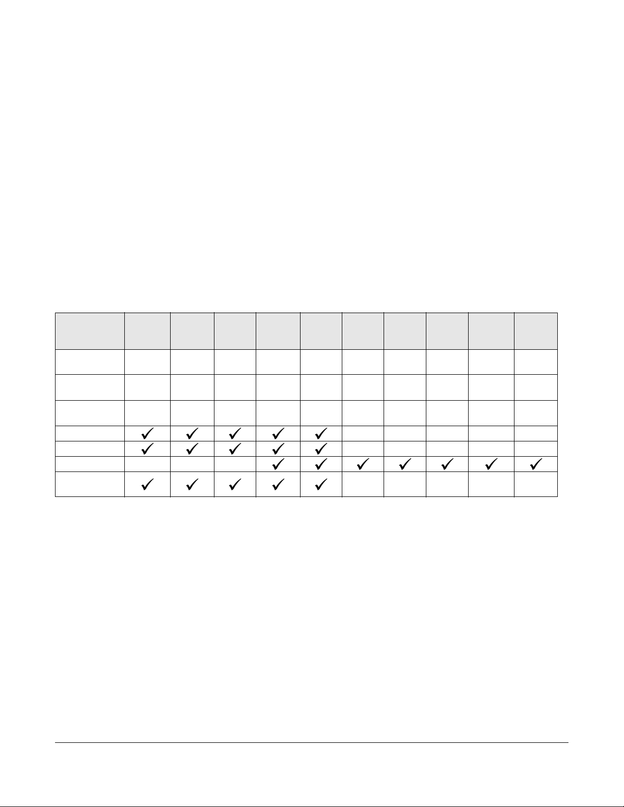
This User’s Guide covers the following models:
Table 1 GS1900 Series Comparison Table
GS1900-8 GS1900-
MODEL
100/1000 Mbps
Port
100/1000 Mbps
PoE Port
1G SFP Slots
Fiber
Desktop --- - -
Wall-mount - - - - -
Rack-mount - - -
Power ON/OFF
Switch
8HP
8 - - 16241224 - 48 24
-88--12-24-24
--2---2222
GS190010HP
GS1900-16 GS1900-
24E
GS190024EP
GS1900-24GS1900-
--- - -
24HP/
GS190024HPv2
GS1900-48 GS1900-
48HP/
GS190048HPv2
See the datasheet for a full list of firmware features available on the Switch.
1.2 Example Applications
This section shows a few examples of using the Switch in various network environments. Note that the
Switch in the figure is just an example Switch and not your actual Switch.
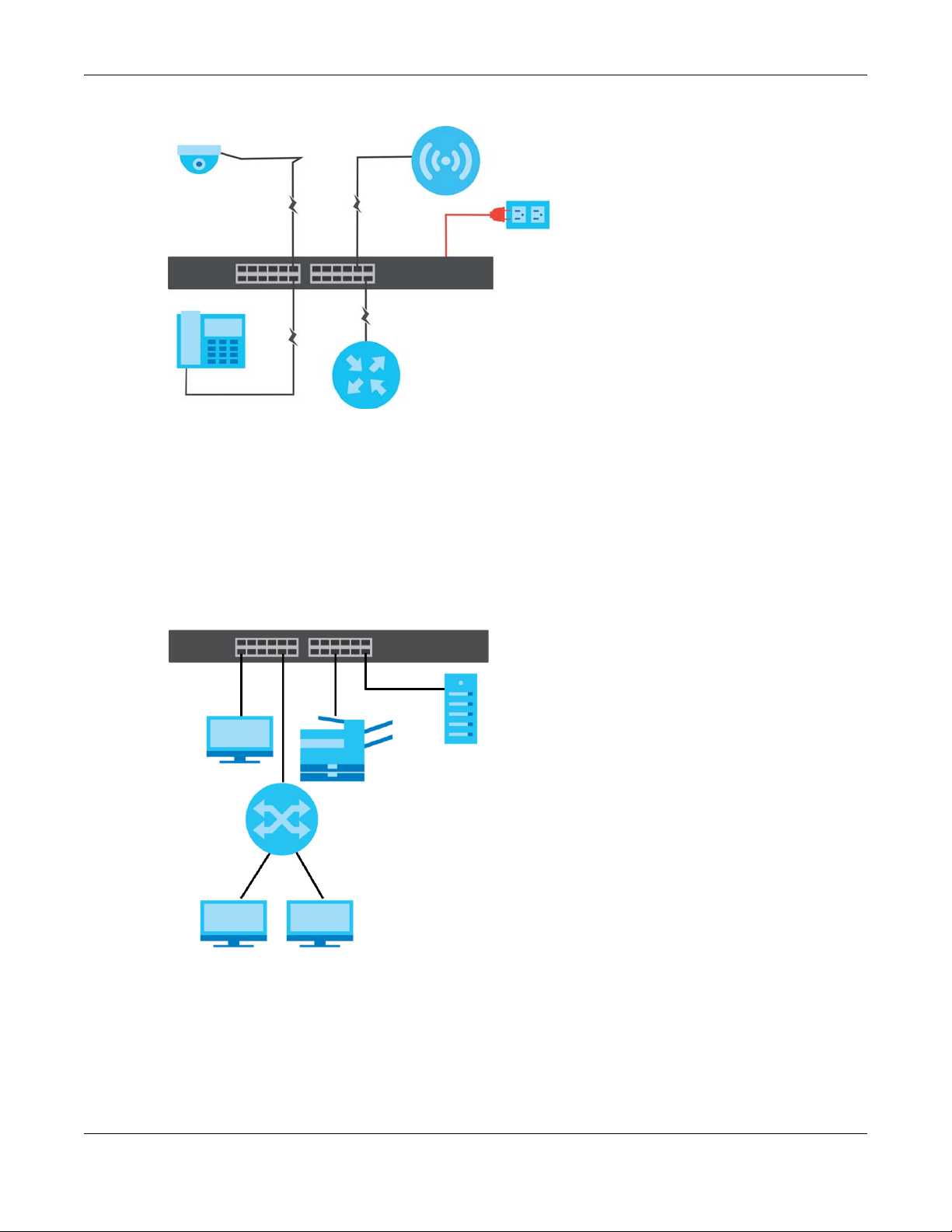
1.2.1 PoE Example Application
The Switch can supply PoE (Power over Ethernet) to Powered Devices (PDs) such as an IP camera, a
wireless router, an IP telephone and a general outdoor router that are not within reach of a power
outlet.
GS1900 Series User’s Guide
17
Chapter 1 Getting to Know Your Switch
Figure 1 PoE Example Application
1.2.2 Backbone Example Application
The Switch is an ideal solution for small networks where rapid growth can be expected in the near future.
The Switch can be used standalone for a group of heavy traffic users. You can connect computers and
servers directly to the Switch’s port or connect other switches to the Switch.
All computers can share high-speed applications on the server. To expand the network, simply add
more networking devices such as switches, routers, computers, print servers, and so on.
Figure 2 Backbone Example Application
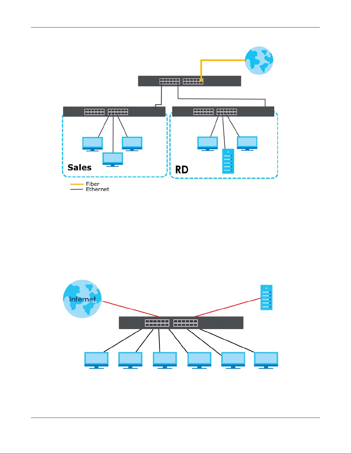
1.2.3 Bridging / Fiber Uplink Example Application
The Switch connects different company departments (RD and Sales) to the corporate backbone. It can
alleviate bandwidth contention and eliminate server and network bottlenecks. All users that need high
bandwidth can connect to high-speed department servers via the Switch. You can provide a super-fast
uplink connection by using a Gigabit Ethernet/SFP port on the Switch.
GS1900 Series User’s Guide
18
Chapter 1 Getting to Know Your Switch
Figure 3 Bridging / Fiber Uplink Example Application
1.2.4 Gigabit Ethernet to the Desktop
The Switch is an ideal solution for small networks which demand high bandwidth for a group of heavy
traffic users. You can connect computers and servers directly to the Switch’s port or connect other
switches to the Switch.
In this example, all computers can share high-speed applications on the server and access the Internet.
To expand the network, simply add more networking devices such as switches, routers, computers, print
servers and so on.
Figure 4 Gigabit to the Desktop
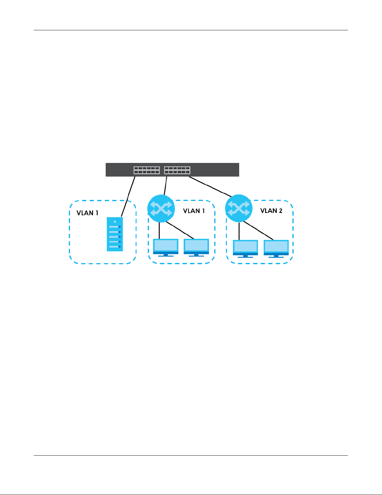
1.2.5 IEEE 802.1Q VLAN Application Example
A VLAN (Virtual Local Area Network) allows a physical network to be partitioned into multiple logical
networks. Stations on a logical network belong to one or more groups. With VLAN, a station cannot
GS1900 Series User’s Guide
19
Chapter 1 Getting to Know Your Switch
directly talk to or hear from stations that are not in the same group(s) unless such traffic first goes through
a router.
For more information on VLANs, refer to Chapter 9 on page 74.
1.2.5.1 Tag-based VLAN Example
Ports in the same VLAN group share the same frame broadcast domain, thus increasing network
performance by reducing broadcast traffic. VLAN groups can be modified at any time by adding,
moving or changing ports without any re-cabling.
Shared resources such as a server can be used by all ports in the same VLAN as the server. In the
following figure only ports that need access to the server need to be part of VLAN 1. Ports can belong to
other VLAN groups too.
Figure 5 Shared Server Using VLAN Example
1.2.6 IPv6 Support
IPv6 (Internet Protocol version 6), is designed to enhance IP address size and features. The increase in
IPv6 address size to 128 bits (from the 32-bit IPv4 address) allows up to 3.4 x 10
of writing, the Switch supports the following features.
• Static address assignment and stateless auto-configuration
• Neighbor Discovery Protocol (a protocol used to discover other IPv6 devices in a network)
• Remote Management using PING, telnet, SNMP, HTTP and TFTP services
• ICMPv6 to report errors encountered in packet processing and perform diagnostic functions, such as
"PING”
• IPv4/IPv6 dual stack; the Switch can run IPv4 and IPv6 at the same time
• DHCPv6 client
1.3 Ways to Manage the Switch
Use any of the following methods to manage the Switch.
GS1900 Series User’s Guide
38
IP addresses. At the time
20

• Web Configurator. This is recommended for everyday management of the Switch using a (supported)
web browser. See Chapter 5 on page 43.
• TFTP. Use Trivial File Transfer Protocol for firmware upgrades and configuration backup/restore. See
Section 33.1 on page 229, Section 33.3 on page 232, and Section 33.4 on page 233.
• SNMP. The device can be configured by a SNMP manager. See Section 32.3 on page 215.
• ZON Utility. ZON Utility is a program designed to help you deploy and perform initial setup on a
network more efficiently. See Section 4.1 on page 38.
1.4 Good Habits for Managing the Switch
Do the following things regularly to make the Switch more secure and to manage the Switch more
effectively.
• Change the password. Use a password that is not easy to guess and that consists of different types of
characters, such as numbers and letters.
• Write down the password and put it in a safe place.
• Back up the configuration (and make sure you know how to restore it). Restoring an earlier working
configuration may be useful if the device becomes unstable or even crashes. If you forget your
password, you will have to reset the Switch to its factory default settings. If you backed up an earlier
configuration file, you would not have to totally re-configure the Switch. You could simply restore your
last configuration.
GS1900 Series User’s Guide
21

Chapter 2 Hardware Installation and Connection
Hardware Installation and
This chapter shows you how to install and connect the Switch.
2.1 Installation Scenarios
This chapter shows you how to install and connect the Switch.
CHAPTER 2
Connection
The Switch can be:
• Placed on a desktop.
• Mounted on a wall.
• Rack-mounted on a standard EIA rack.
Note: Ask an authorized technician to attach the Switch to the rack/wall. See the Installation
Requirements sections in this chapter to know the types of screws and screwdrivers for
wall-mounting.
WARNING! Failure to use the proper screws may damage the unit.
Make sure you connect the Switch’s power cord to a socket-outlet with
an earthing connection or its equivalent.
WARNING! This Switch is not suitable for use in locations where children
are likely to be present.
See Table 1 on page 17 for the comparison table of the hardware installation methods for each model.
2.2 Desktop Installation Procedure
1 Make sure the Switch is clean and dry.
2 Set the Switch on a smooth, level surface strong enough to support the weight of the Switch and the
connected cables. Make sure there is a power outlet nearby.
GS1900 Series User’s Guide
22
Chapter 2 Hardware Installation and Connection
3 Make sure there is at least 40 mm of clearance from the bottom to the Switch, and make sure there is
enough clearance around the Switch to allow air circulation and the attachment of cables and the
power cord. This is especially important for enclosed rack installations.
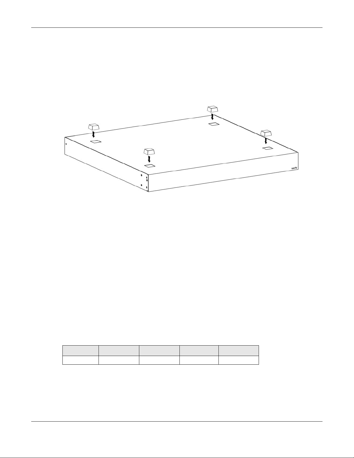
4 Remove the adhesive backing from the rubber feet.
5 Attach the rubber feet to each corner on the bottom of the Switch. These rubber feet help protect the
Switch from shock or vibration and ensure space between devices when stacking.
Figure 6 Attaching Rubber Feet
Note: Do NOT block the ventilation holes. Leave space between devices when stacking.
Note: For proper ventilation, allow at least 4 inches (10 cm) of clearance at the front and 3.4
inches (8 cm) at the back of the Switch. This is especially important for enclosed rack
installations.
2.3 Wall Mounting
You may need screw anchors if mounting on a concrete or brick wall.
2.3.1 Wall-mounted Installation Requirement
The following are the wall-mounted installation requirements:
• Use screws with 6 mm ~ 8 mm (0.24" ~ 0.31") wide heads.
• See the following table for how far apart to place the screws.
Table 2 Distance between the centers of the holes for wall mounting
GS1900-8 GS1900-8HP GS1900-10HP GS1900-16 GS1900-24E
176 mm 176 mm 176 mm 148 mm 207 mm
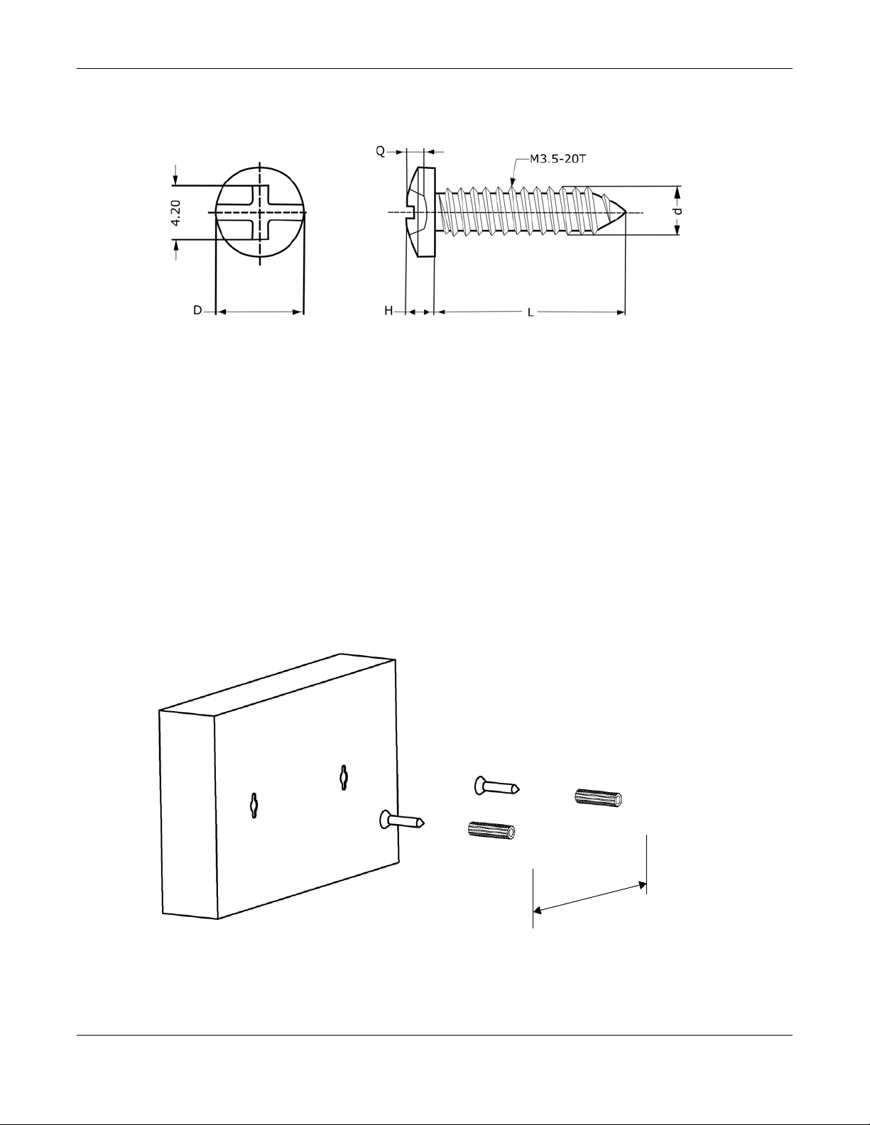
The following figure shows the screw specifications used for wall mounting.
• D = 7.00 mm
• H = 2.00 mm
• L= 15.50 mm
GS1900 Series User’s Guide
23
Chapter 2 Hardware Installation and Connection
• d = 3.50 mm
Do the following to attach your Switch to a wall.
1 Select a position free of obstructions on a wall strong enough to hold the weight of the Switch.
2 Mark two holes on the wall at the appropriate distance apart for the screws.
WARNING! Be careful to avoid damaging pipes or cables located inside
the wall when drilling holes for the screws.
3 If using screw anchors, drill two holes for the screw anchors into the wall. Push the anchors into the full
depth of the holes, then insert the screws into the anchors. Do not insert the screws all the way in - leave
a small gap. The gap must be big enough for the screw heads to slide into the screw slots and the
connection cables to run down the back of the Switch.
If not using screw anchors, use a screwdriver to insert the screws into the wall. Do not insert the screws all
the way in - leave a gap.
Note: Make sure the screws are fastened well enough to hold the weight of the Switch with
the connection cables.
4 Align the holes on the back of the Switch with the screws on the wall. Hang the Switch on the screws.
GS1900 Series User’s Guide
24
Chapter 2 Hardware Installation and Connection
Note: Make sure there is enough clearance between the wall and the Switch to allow
ventilation.
The Switch should be wall-mounted horizontally. The Switch's side
panels with ventilation slots should not be facing up or down as this
position is less safe.
2.4 Rack Mounting
The Switch can be mounted on an EIA standard size, 19-inch rack or in a wiring closet with other
equipment. Follow the steps below to mount your Switch on a standard EIA rack using a rack-mounting
kit.
Note: Make sure there is enough clearance between each equipment on the rack for air
circulation.
2.4.1 Rack-mounted Installation Requirements
The following are the rack-mounted installation requirements:
• Two mounting brackets.
• Eight M3 flat head screws and a #2 Philips screwdriver.
• Four M5 flat head screws and a #2 Philips screwdriver.
Failure to use the proper screws may damage the unit.
2.4.1.1 Precautions
• Make sure the rack will safely support the combined weight of all the equipment it contains.
• Make sure the position of the Switch does not make the rack unstable or top-heavy. Take all
necessary precautions to anchor the rack securely before installing the unit.
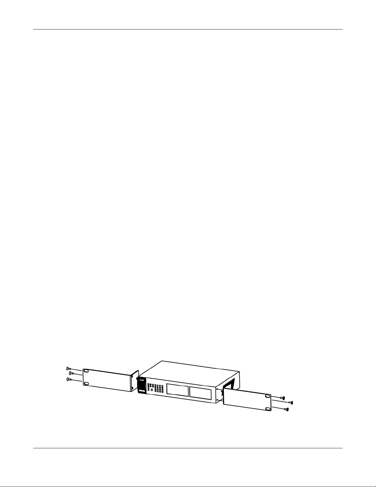
2.4.2 Attaching the Mounting Brackets to the Switch
1 Position a mounting bracket on one side of the Switch, lining up the four screw holes on the bracket with
the screw holes on the side of the Switch.
Figure 7 Attaching the Mounting Brackets (GS1900-16, GS1900-24E, and GS1900-24EP)
GS1900 Series User’s Guide
25
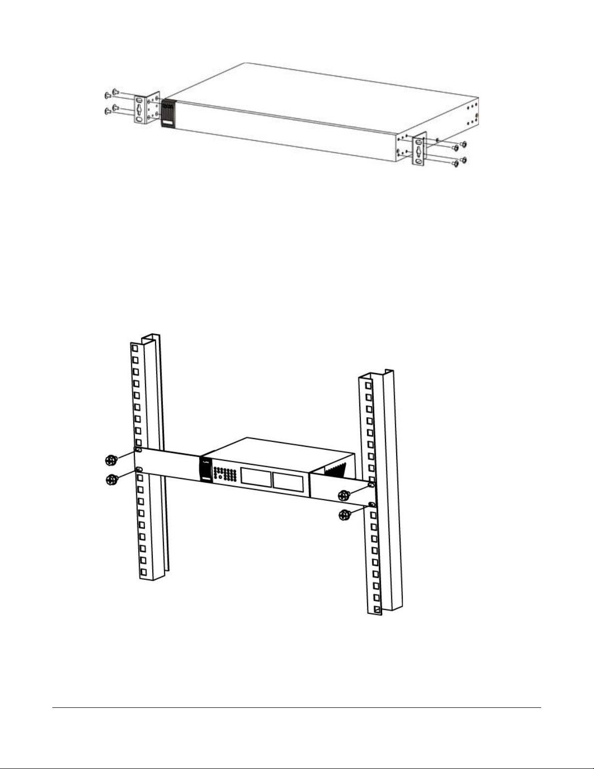
Figure 8 Attaching the Mounting Brackets (GS1900-24, GS1900-24HP/GS1900-24HPv2, GS1900-48, and
GS1900-48HP/GS1900-48HPv2)
2 Using a #2 Philips screwdriver, install the M3 flat head screws through the mounting bracket holes into
the Switch.
3 Repeat steps 1 and 2 to install the second mounting bracket on the other side of the Switch.
4 You may now mount the Switch on a rack. Proceed to the next section.
2.4.3 Mounting the Switch on a Rack
1 Position a mounting bracket (that is already attached to the Switch) on one side of the rack, lining up
the two screw holes on the bracket with the screw holes on the side of the rack.
Figure 9 Mounting the Switch on a Rack (GS1900-16, GS1900-24E, and GS1900-24EP)
GS1900 Series User’s Guide
26
Chapter 2 Hardware Installation and Connection
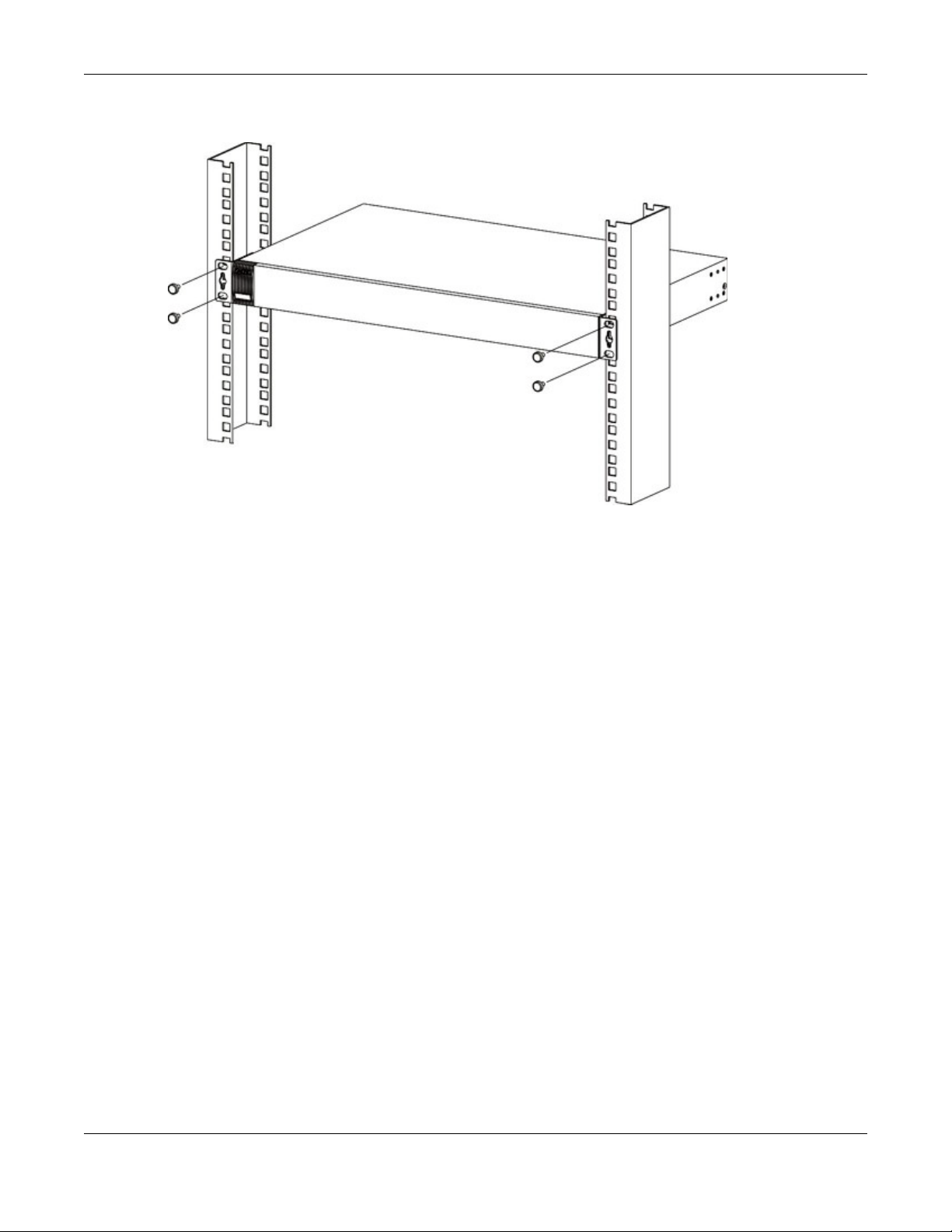
Figure 10 Mounting the Switch on a Rack (GS1900-24, GS1900-24HP/GS1900-24HPv2, GS1900-48, and
GS1900-48HP/GS1900-48HPv2)
2 Using a #2 Philips screwdriver, install the M5 flat head screws through the mounting bracket holes into
the rack.
Note: Make sure you tighten all the four screws to prevent the Switch from getting slanted.
3 Repeat steps 1 and 2 to attach the second mounting bracket on the other side of the rack.
GS1900 Series User’s Guide
27
Chapter 3 Hardware Overview
Revision A1
Revision B1
Hardware Overview
This chapter describes the front panel and rear panel of the Switch and shows you how to make the
hardware connections.
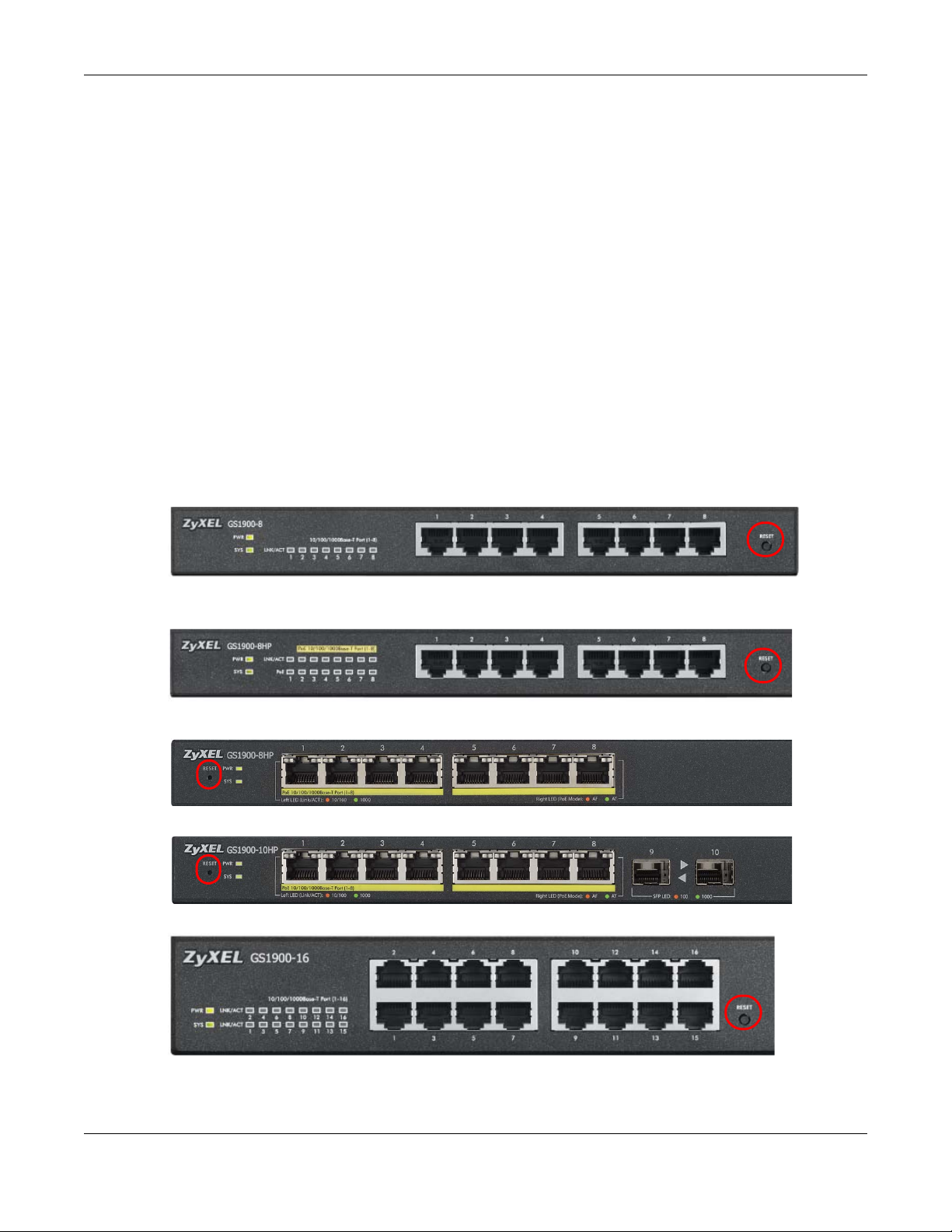
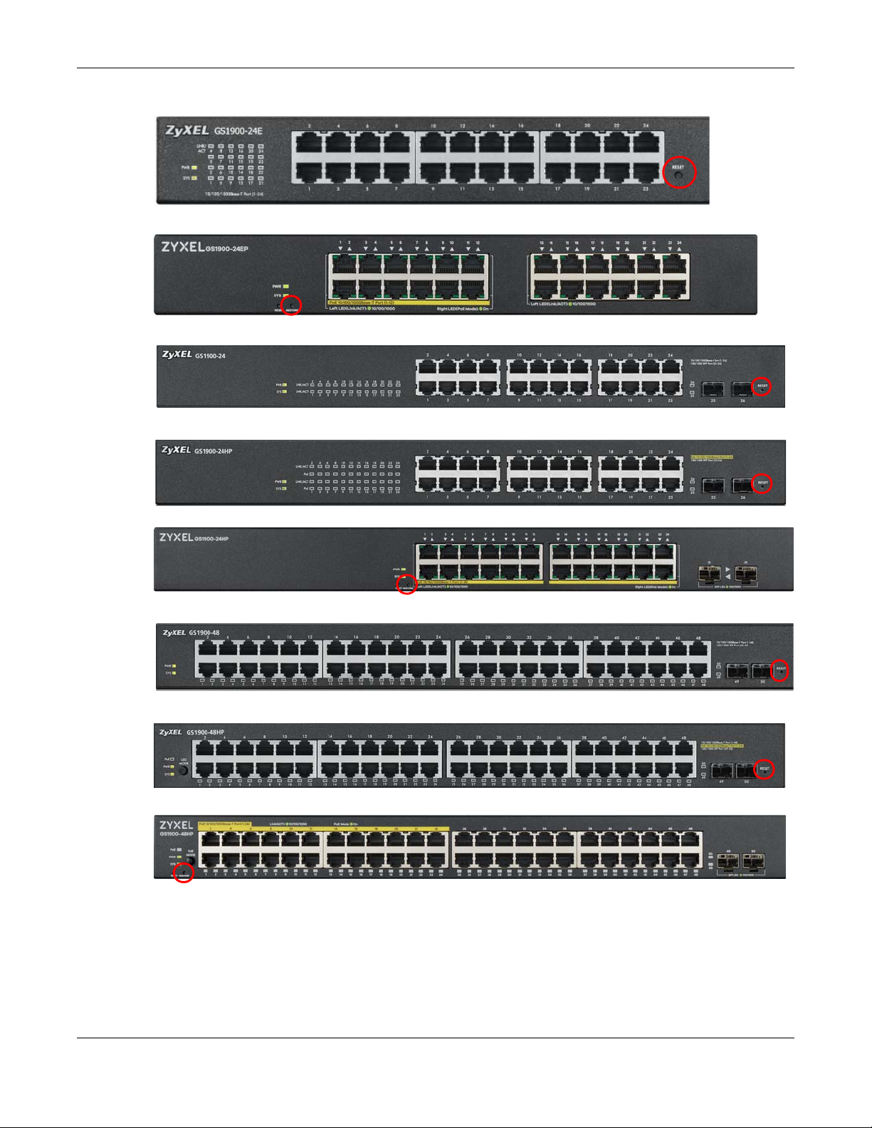
3.1 Front Panel Connections
The following figures show the front panels of the Switch.
Figure 11 Front Panel: GS1900-8
CHAPTER 3
Figure 12 Front Panel: GS1900-8HP
Figure 13 Front Panel: GS1900-10HP
Figure 14 Front Panel: GS1900-16
GS1900 Series User’s Guide
28
Chapter 3 Hardware Overview
Figure 15 Front Panel: GS1900-24E
Figure 16 Front Panel: GS1900-24EP
Figure 17 Front Panel: GS1900-24
Figure 18 Front Panel: GS1900-24HP
Figure 19 Front Panel: GS1900-24HPv2
Figure 20 Front Panel: GS1900-48
Figure 21 Front Panel: GS1900-48HP
Figure 22 Front Panel: GS1900-48HPv2
3.1.1 Ethernet Ports
The Switch has 1000Base-T auto-negotiating, auto-crossover Ethernet ports. In 10/100/1000 Mbps Gigabit
Ethernet, the speed can be 10Mbps, 100 Mbps or 1000 Mbps. The duplex mode can be both half or full
duplex at 100 Mbps and full duplex only at 1000 Mbps.
GS1900 Series User’s Guide
29
An auto-negotiating port can detect and adjust to the optimum Ethernet speed (10/100/1000 Mbps)
and duplex mode (full duplex or half duplex) of the connected device.
An auto-crossover (auto-MDI/MDI-X) port automatically works with a straight-through or crossover
Ethernet cable.
3.1.1.1 Default Ethernet Settings
The factory default negotiation settings for the Ethernet ports on the Switch are:
• Speed: Auto
•Duplex: Auto
• Flow control: Off
3.1.2 SFP Slots
These are slots for Small Form-Factor Pluggable (SFP) transceivers. A transceiver is a single unit that
houses a transmitter and a receiver. Use a transceiver to connect a fiber-optic cable to the Switch. The
Switch does not come with transceivers. You must use transceivers that comply with the Small FormFactor Pluggable (SFP) Transceiver MultiSource Agreement (MSA). See the SFF committee’s INF-8074i
specification Rev 1.0 for details.
Chapter 3 Hardware Overview
You can change transceivers while the Switch is operating. You can use different transceivers to
connect to Ethernet switches with different types of fiber-optic connectors.
• Type: SFP connection interface
• Connection speed: 1 Gigabit per second (Gbps)
To avoid possible eye injury, do not look into an operating fiber-optic
module’s connectors.
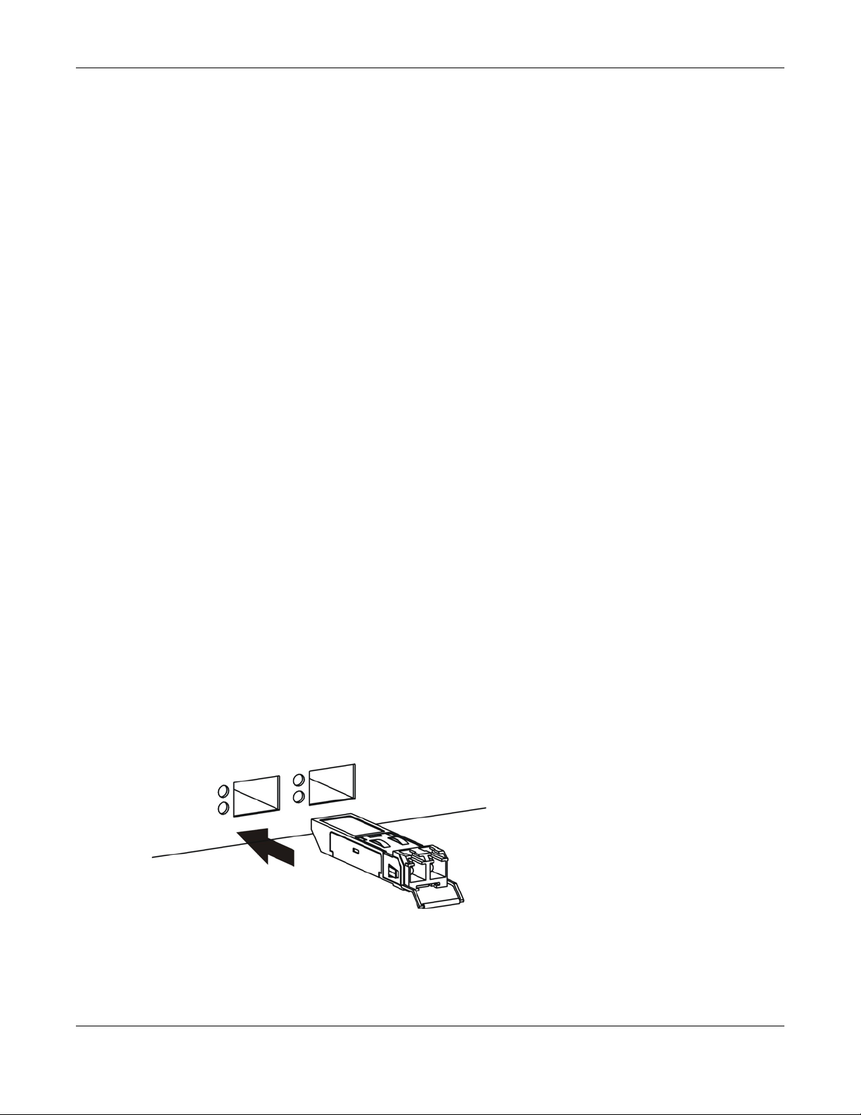
3.1.2.1 Transceiver Installation
Use the following steps to install a transceiver.
1 Insert the transceiver into the slot with the exposed section of PCB board facing down.
Figure 23 Transceiver Installation Example
2 Press the transceiver firmly until it clicks into place.
GS1900 Series User’s Guide
30

3 The Switch automatically detects the installed transceiver. Check the LEDs to verify that it is functioning
properly.
Figure 24 Installed Transceiver
3.1.2.2 Transceiver Removal
Use the following steps to remove a transceiver.
1 Open the transceiver’s latch (latch styles vary).
Figure 25 Opening the Transceiver’s Latch Example
Chapter 3 Hardware Overview
2 Pull the transceiver out of the slot.
Figure 26 Transceiver Removal Example
3.1.3 PoE Mode (GS1900-48HP and GS1900-48HPv2 only)
Push or release this button (see Figure 21 on page 29) to change how the Link/ACT LED works.
• Each Ethernet port’s LED is changed to act as a PoE Mode LED by pushing the PoE MODE button on
the front panel.
• Each Ethernet port’s LED is changed back to act as a Link/ACT LED by releasing the PoE MODE button
on the front panel.
View the LEDs to ensure proper functioning of the Switch and as an aid in troubleshooting (see Section
3.3 on page 35).
3.2 Rear Panel
The following figures show the rear panels of the Switch.
GS1900 Series User’s Guide
31

Chapter 3 Hardware Overview
Revision B1
Revision A1
Figure 27 Rear Panel: GS1900-8
Figure 28 Rear Panel: GS1900-8HP
Figure 29 Rear Panel: GS1900-10HP
Figure 30 Rear Panel: GS1900-16
Figure 31 Rear Panel: GS1900-24E
Figure 32 Rear Panel: GS1900-24EP
Figure 33 Rear Panel: GS1900-24
GS1900 Series User’s Guide
32

Chapter 3 Hardware Overview
Figure 34 Rear Panel: GS1900-24HP
Figure 35 Rear Panel: GS1900-24HPv2
Figure 36 Rear Panel: GS1900-48
Figure 37 Rear Panel: GS1900-48HP
Figure 38 Rear Panel: GS1900-48HPv2
3.2.1 Grounding
Grounding is a safety measure to have unused electricity return to the ground. It prevents damage to
the Switch, and protects you from electrocution.
Any device that is located outdoors and connected to this product must be properly grounded and
surge protected. To the extent permissible by applicable law, failure to follow these guidelines could
result in damage to your Switch which may not be covered by its warranty.
Note: The Switch must be grounded by qualified service personnel.
1 Remove the M4 ground screw from the Switch’s rear panel.
2 Secure a green/yellow ground cable (16 AWG or smaller) to the Switch's rear panel using the M4 ground
screw.
3 Attach the other end of the cable to the ground, either to the same ground electrode as the rack you
installed the device on or to the main grounding electrode of the building.
Follow your country's regulations and safety instructions to electrically ground the device properly.
if you are uncertain that suitable grounding is available, contact the appropriate electrical inspection
authority or an electrician.
GS1900 Series User’s Guide
33

Warning! Connect the ground cable before you connect any other
cables or wiring.
Figure 39 Grounding
3.2.2 Power Connection
Make sure you are using the correct power source and that no objects obstruct the airflow of the fans.
The Switch uses two power supply modules, one of which is redundant, so if one power module fails the
system can operate on the remaining module.
Rear Panel Power Connection
Connect one end of the supplied power cord or power adapter to the power receptacle on the back
of the Switch and the other end to the appropriate power source.
For Switches with a power switch (see Table 1 on page 17), use the POWER ON/OFF switch to have the
Switch power on or off.
Connecting the Power
Use the following procedures to connect the Switch to a power source after you have installed it in a
rack.
Note: Use the included power cord for the AC power connection.
1 Connect the female end of the power cord to the AC power socket.
2 Connect the other end of the cord to a power outlet.
Disconnecting the Power
The power input connectors can be disconnected from the power source individually.
1 Disconnect the power cord from the power outlet.
2 Disconnect the power cord from the AC power socket.
GS1900 Series User’s Guide
34

Chapter 3 Hardware Overview
RightLeft
3.3 LEDs
After you connect the power to the Switch, view the LEDs to ensure proper functioning of the Switch
and as an aid in troubleshooting.
Table 3 LED Descriptions
LED COLOR STATUS DESCRIPTION
PWR Green On The system is turned on.
Off The system is off or has failed.
SYS Green On The system is on and functioning properly.
Blinking The system is rebooting and performing self-diagnostic tests.
Off The power is off or the system is not ready/malfunctioning.
Ethernet Ports
LNK/ACT Green Blinking The system is transmitting/receiving to/from a 100/1000 Mbps Ethernet network.
On The link to a 100/1000 Mbps Ethernet network is up.
Off The link to an Ethernet network is down.
PoE
(see Section 1.1
on page 17)
1G SFP Slots (Fiber Ports - see Section 1.1 on page 17)
LNK/ACT Green Blinking The system is transmitting/receiving to/from a 100/1000 Mbps Fiber network.
Green On Power is supplied to all PoE Ethernet ports.
Off There is no power supplied.
On The link to a 100/1000 Mbps Fiber network is up.
Off The link to a Fiber network is down.
Table 4 LED Descriptions (GS1900-8HP (Revision B1) and GS1900-10HP Only)
LED COLOR STATUS DESCRIPTION
PWR Green On The system is turned on.
Off The system is off or has failed.
SYS Green On The system is on and functioning properly.
Blinking The system is rebooting.
Red On There is a system error.
PoE 10/100/1000Base-T Ports (1-8), 2 LEDs per port
Right Amber On The port is in PoE AF mode. That is, the Switch is following the IEEE 802.3af standard to
Green On The port is in PoE AT mode. That is, the Switch is following the IEEE 802.3at standard to
Off Power is not supplied to this port.
supply power to this port.
supply power to this port.
GS1900 Series User’s Guide
35

Chapter 3 Hardware Overview
Table 4 LED Descriptions (continued)(GS1900-8HP (Revision B1) and GS1900-10HP Only)
LED COLOR STATUS DESCRIPTION
Left Amber On The link to a 10/100 Mbps Ethernet network is up.
Blinking The system is transmitting/receiving to/from a 100/1000 Mbps Fiber network.
Green On The link to a 1 Gbps Ethernet network is up.
Blinking The system is transmitting/receiving to/from 1 Gbps Mbps Ethernet network.
LED Descriptions for SFP Port (GS1900-10HP Only)
LED COLOR STATUS DESCRIPTION
Two arrow LEDs for 1G SFP Slots (Fiber Ports)
right/left arrows Amber On The link to a 100 Mbps Fiber network is up.
Blinking The system is transmitting/receiving to/from a 100 Mbps Fiber network.
Green On The link to a 1 Gbps Fiber network is up.
Blinking The system is transmitting/receiving to/from 1 Gbps Mbps Fiber network.
3.4 Resetting the Switch (all models except GS1900-24EP/ GS1900-24HPv2/GS1900-48HPv2)
If you lock yourself (and others) from the Switch, or you forget your password, or cannot access the Web
Configurator, you will need to reload the factory-default configuration file. Or use the RESET button at
the front of the device.
This means that you will lose all configurations that you had previously and the default Switch IP address,
user name and password will be reset to 192.168.1.1, admin and 1234 respectively.
If you backed up an earlier configuration file as advised in Section 1.4 on page 21, you will not have to
totally re-configure the Switch after resetting. You can simply restore your last configuration.
Follow the steps below to reset the Switch back to factory defaults.
1 Make sure the SYS LED is steady green (not blinking). Use a pointed instrument such as a pin to access
the RESET button on the front of the Switch as shown in Section 3.1 on page 28.
2 Press the button for more than 6 seconds. After releasing the button, the SYS LED begins to blink. Wait for
the Switch to restart (the SYS LED will be steady green again). This takes up to two minutes.
GS1900 Series User’s Guide
36

Chapter 3 Hardware Overview
Note: If you want to access the Switch Web Configurator again, you may need to change
the IP address of your computer to be in the same subnet as that of the default Switch
IP address (192.168.1.1).
3.5 Resetting the Switch (GS1900-24EP/GS1900-24HPv2/ GS1900-48HPv2 only)
Use the RESTORE button to reset the Switch back to factory defaults. Use the RESET button to reboot the
Switch.
3.5.1 Restore Button
Press the RESTORE button for more than 6 seconds until the SYS LED begins to blink. The Switch will
automatically reboot and restore the factory default file. See Section 3.3 on page 35 for more
information about the LED behavior.
3.5.2 Reboot the Switch
Press the RESET button to reboot the Switch without turning the power off. See Section 3.3 on page 35 for
more information about the LED behavior.
GS1900 Series User’s Guide
37

Chapter 4 ZON Utility
CHAPTER 4
ZON Utility
This chapter describes the screens for ZON Utility.
4.1 Zyxel One Network (ZON) Utility Screen
ZON Utility is a program designed to help you deploy and manage a network more efficiently. It detects
devices automatically and allows you to do basic settings on devices in the network without having to
be near it.
The ZON Utility issues requests via Zyxel Discovery Protocol (ZDP) and in response to the query, the device
responds back with basic information including IP address, firmware version, location, system and model
name in the same broadcast domain. The information is then displayed in the ZON Utility screen and you
can perform tasks like basic configuration of the devices and batch firmware upgrade in it. You can
download the ZON Utility at www.zyxel.com and install it on a PC (Windows operating system).
4.1.1 Requirements
Before installing the ZON Utility on your PC, please make sure it meets the requirements listed below.
Operating System
At the time of writing, the ZON Utility is compatible with:
• Windows 7 (both 32-bit / 64-bit versions)
• Windows 8 (both 32-bit / 64-bit versions)
• Windows 8.1 (both 32-bit / 64-bit versions)
• Window 10 (both 32-bit / 64-bit versions)
Note: To check for your Windows operating system version, right-click on My Computer >
Properties. You should see this information in the General tab.
Note: It is suggested that you install Npcap, the packet capture library for Windows operating
systems, and remove WinPcap or any other installed packet capture tools before you
install the ZON utility.
Hardware
Here are the minimum hardware requirements to use the ZON Utility on your PC.
GS1900 Series User’s Guide
38

• Core i3 processor
•2GB RAM
• 100MB free hard disk
• WXGA (Wide XGA 1280x800)
4.1.2 Run the ZON Utility
1 Double-click the ZON Utility to run it.
2 The first time you run the ZON Utility, you will see if your device and firmware version support the ZON
Utility. Click the OK button to close this screen.
Figure 40 Supported Devices and Versions
Chapter 4 ZON Utility
If you want to check the supported models and firmware versions later, you can click the Show
information about ZON icon in the upper right hand corner of the screen. Then select the Supported
model and firmware version link. If your device is not listed here, see the device release notes for ZON
utility support. The release notes are in the firmware zip file on the Zyxel web site.
GS1900 Series User’s Guide
39

Figure 41 ZON Utility Screen
Chapter 4 ZON Utility
3 Select a network adapter to which your supported devices are connected.
4 Click the Go button for the ZON Utility to discover all supported devices in your network.
Figure 42 Discovery
5 The ZON Utility screen shows the devices discovered.
GS1900 Series User’s Guide
40

Figure 43 ZON Utility Screen
1
2
3
4
56
7
8
9
10 11 12 13
Chapter 4 ZON Utility
6 Select a device and then use the icons to perform actions. Some functions may not be available for
your devices.
Note: You must know the selected device admin password before taking actions on the
device using the ZON utility icons.
Figure 44 Password Prompt
The following table describes the icons numbered from left to right in the ZON Utility screen.
Table 5 ZON Utility Icons
ICON DESCRIPTION
1 IP configuration Change the selected device’s IP address.
2 Renew IP Address Update a DHCP-assigned dynamic IP address.
3 Reboot Device Use this icon to restart the selected device(s). This may be useful when troubleshooting
or upgrading new firmware.
GS1900 Series User’s Guide
41

Chapter 4 ZON Utility
Table 5 ZON Utility Icons
ICON DESCRIPTION
4 Reset Configuration to
Default
5 Locator LED Use this icon to locate the selected device by causing its Locator LED to blink.
6 Web GUI Use this to access the selected device web configurator from your browser. You will
7 Firmware Upgrade Use this icon to upgrade new firmware to selected device(s) of the same model.
8 Change Password Use this icon to change the admin password of the selected device. You must know
9 Configure NCC
Discovery
10 ZAC Use this icon to run the Zyxel AP Configurator of the selected AP.
11 Clear and Rescan Use this icon to clear the list and discover all devices on the connected network again.
12 Save Configuration Use this icon to save configuration changes to permanent memory on a selected
13 Settings Use this icon to select a network adapter for the computer on which the ZON utility is
If you forget your password or cannot access the Web Configurator, you can use this
icon to reload the factory-default configuration file. This means that you will lose all
configurations that you had previously.
need a username and password to log in.
Online upgrade: If there’s the latest firmware available, it’ll show in the drop-down
menu. You don’t need to download the firmware first to upgrade firmware.
Local upgrade: Make sure you have downloaded the firmware from the Zyxel website
to your computer and unzipped it in advance.
the current admin password before changing to a new one.
You must have Internet access to use this feature. Use this icon to enable or disable the
Nebula Control Center (NCC) discovery feature on the selected device. If it’s
enabled, the selected device will try to connect to the NCC. Once the selected
device is connected to and has registered in the NCC, it’ll go into the Nebula cloud
management mode.
device.
installed, and the utility language.
The following table describes the fields in the ZON Utility main screen.
Table 6 ZON Utility Fields
LABEL DESCRIPTION
Type This field displays an icon of the kind of device discovered.
Model This field displays the model name of the discovered device.
Firmware Version This field displays the firmware version of the discovered device.
MAC Address This field displays the MAC address of the discovered device.
IP Address This field displays the IP address of an internal interface on the discovered device that first
received an ZDP discovery request from the ZON utility.
System Name This field displays the system name of the discovered device.
Location This field displays where the discovered device is.
Status This field displays whether changes to the discovered device have been done
NCC Discovery This field displays if the discovered device supports the Nebula Control Center (NCC)
Serial Number Enter the admin password of the discovered device to display its serial number.
Hardware Version This field displays the hardware version of the discovered device.
successfully. As the Switch does not support IP Configuration, Renew IP address and
Locator LED, this field displays “Update failed”, “Not support Renew IP address” and “Not
support Flash Locator LED” respectively.
discovery feature. If it’s enabled, the selected device will try to connect to the NCC. Once
the selected device is connected to and has registered in the NCC, it’ll go into the Nebula
cloud management mode.
GS1900 Series User’s Guide
42
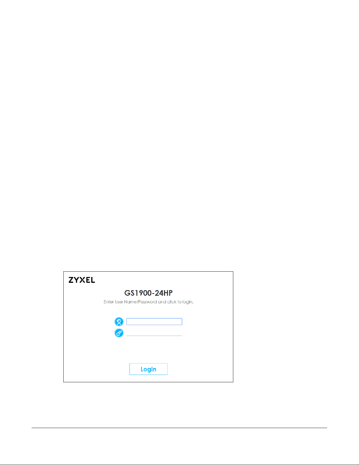
5.1 Overview
This section introduces the configuration and functions of the Web Configurator.
The Web Configurator is an HTML-based management interface that allows easy Switch setup and
management via Internet browser. Use a browser that supports HTML5, such as Internet Explorer 11,
Mozilla Firefox, or Google Chrome. The recommended screen resolution is 1024 by 768 pixels.
In order to use the Web Configurator, you need to allow:
• Web browser pop-up windows
• JavaScript (enabled by default)
• Java permissions (enabled by default)
CHAPTER 5
Web Configurator
5.2 Access
1 Make sure your Switch hardware is properly connected. See the Quick Start Guide.
2 Browse to https://192.168.1.1. The Login screen appears.
Figure 45 The Login Screen
3 Enter the user name (default: “admin”) and password (default: “1234”).
4 Click Login. If you logged in using the default user name and password, getting start appears. The
Getting Start screen appears every time you log in using the default user name and default password.
GS1900 Series User’s Guide
43

Chapter 5 Web Configurator
5 If you did not change the default administrator password and/or SNMP community values, a warning
screen displays each time you log into the Web Configurator. Click Password / SNMP to open a screen
where you can change the administrator and SNMP passwords simultaneously. Otherwise, click Ignore
to close it.
Figure 46 Web Configurator: Warning
Figure 47 Web Configurator: Password
Change the default administrator and/or SNMP passwords, and then click Apply to save your changes.
Table 7 Web Configurator: Password > Users/SNMP
LABEL DESCRIPTION
User This is the default administrator account with the “admin” user name. You cannot change the
default administrator user name.
Old Password Type the existing system password (1234 is the default password when shipped).
New Password Enter your new system password.
New Password
Confirm
SNMP
Use this section to specify the SNMP community (password) and access right values.
Community Enter a string identifying the community name that this entry should belong to. The allowed
Access Right Select the access mode for this entry. The possible values are Read-Only and Read-Write.
Retype your new system password for confirmation.
string length is 1 to 20, and the allowed content is ASCII characters from 33 to 126.
GS1900 Series User’s Guide
44

Chapter 5 Web Configurator
A
B
C
Table 7 Web Configurator: Password > Users/SNMP (continued)
LABEL DESCRIPTION
Apply Click Apply to save your changes to the Switch’s run-time memory. The Switch loses these
changes if it is turned off or loses power, so use the Save link on the top navigation panel to
save your changes to the non-volatile memory when you are done configuring.
Cancel Click Cancel to begin configuring this screen afresh.
5.3 Navigating the Web Configurator
The following summarizes how to navigate the Web Configurator from the Getting Start screen. This
guide uses the GS1900-24HP screens as an example. The screens may vary slightly for different models.
Figure 48 The Web Configurator’s Main Screen
The Web Configurator’s main screen is divided into these parts:
• A - Title Bar
• B - Navigation Panel
• C - Main Window
5.3.1 Title Bar
The title bar provides some useful links that always appear over the screens below, regardless of how
deep into the Web Configurator you navigate.
Figure 49 Title Bar
The icons provide the following functions.
Table 8 Title Bar: Web Configurator Icons
LABEL DESCRIPTION
Refresh Click Refresh to reload the page.
Save Click this to apply your changes to the Switch’s run-time memory. The Switch loses these
Status Click this to display basic information about the Switch.
changes if it is turned off or loses power, so use the Save link on the top navigation panel to
save your changes to the non-volatile memory when you are done configuring.
GS1900 Series User’s Guide
45

Table 8 Title Bar: Web Configurator Icons (continued)
LABEL DESCRIPTION
Logout Click this to log out of the Web Configurator.
Help Click this to open the help page for the current screen.
Click Logout in a screen to exit the Web Configurator. You have to log in with your password again after
you log out. This is recommended after you finish a management session for security reasons.
5.3.2 Navigation Panel
Use the menu items on the navigation panel to open screens to configure Switch features. The following
sections introduce the Switch’s navigation panel menus and their screens.
Figure 50 Navigation Panel
Chapter 5 Web Configurator
Getting Start
Getting Start displays general device information, system status, system resource usage, and interface
status.
For details on Getting Start features, see Chapter 6 on page 52.
GS1900 Series User’s Guide
46

Chapter 5 Web Configurator
Monitor Menu
The monitor menu screens display status and statistics information.
Table 9 Monitor Menu Screens Summary
FOLDER OR LINK TAB FUNCTION
System This link takes you to a screen where you can see general identification
information for the Switch.
IP IPv4 This link takes you to a screen where you can see an IPv4 interface and
the IPv4 settings on the Switch.
IPv6 This link takes you to a screen where you can see an IPv6 interface and
Information This link takes you to a screen that displays general system information:
Port This link takes you to screens where you can see speed, flow control and
Port Status Displays status settings for individual Switch ports.
Port Counters Displays interface, port 1 interface mib counters, port 1 etherlike mib
Bandwidth
Utilization
PoE Displays PoE status.
Bandwidth
Management
Storm Control This link takes you to a screen that displays broadcast filters.
VLAN This link takes you to screens where you can see port-based or 802.1Q
VLAN VLAN Displays VLAN settings.
Port Displays port settings.
VLAN Port Displays VLAN port settings.
Guest VLAN Displays global and port settings.
Voice VLAN Displays global and port settings.
MAC Table This link takes you to a screen where you can view the MAC address and
Link Aggregation This link takes you to screen where you can view aggregate physical
Loop Guard This link takes you to a screen where you can view protection against
Multicast This link takes you to screen where you can view various multicast
IGMP VLAN Displays VLAN settings.
Statistics Displays statistics settings.
Group Displays group settings.
Router Displays router settings.
the IPv6 settings on the Switch.
system name, system location, and system contact.
priority settings for individual Switch ports.
counters, port 1 RMON mib counters settings for individual Switch ports.
Displays port bandwidth utilization settings for individual Switch ports.
Displays egress global burst and port rate for individual Switch ports.
VLAN (depending on what you configured in the Switch Setup menu).
You can also see a protocol based VLAN or a subnet based VLAN in
these screens.
VLAN ID of a device attach to a port. You can also view what kind of
MAC address it is.
links to form one logical, higher-bandwidth link.
network loops that occur on the edge of your network.
features, IGMP snooping and create multicast VLANs.
GS1900 Series User’s Guide
47

Chapter 5 Web Configurator
Table 9 Monitor Menu Screens Summary (continued)
FOLDER OR LINK TAB FUNCTION
Spanning Tree This link takes you to screens where you can view CIST, MST, STP
preventing network loops.
CIST Displays CIST instance status.
CIST Port Displays CIST port status.
MST Displays MST instance status.
MST Port Displays MST port status.
STP Statistics Displays STP statistics.
LLDP Displays statistics, remote information, and overloading.
Statistics Displays LLDP global and port statistics.
Remote
Information
Overloading Displays port overloading information.
Security Displays port security and 802.1X settings.
Port Security Displays global and port settings.
802.1X Port Displays 802.1X port settings.
Authenticated
Hosts
Management Displays syslog and error disable.
Syslog Displays logging filter select and show system log.
Error Disable Displays global and port settings.
Displays remote device information.
Displays authenticated hosts table.
Configuration Menu
Use the configuration menu screens to configure the Switch’s features.
Table 10 Configuration Menu Screens Summary
FOLDER OR LINK TAB FUNCTION
System This link takes you to a screen where you can configure general
identification information and time settings for the Switch.
IP IPv4 This link takes you to a screen where you can enable an IPv4
interface and configure the IPv4 settings on the Switch.
IPv6 This link takes you to a screen where you can enable an IPv6
Time System Time Configure time of system.
SNTP Server Configure SNTP server settings.
Information This link takes you to a screen that configures general system
Port This link takes you to screens where you can configure speed, flow
Port Configure port settings for individual Switch ports.
EEE Configure EEE settings for individual Switch ports.
PoE Global This link takes you to a screen where you can configure the global
Port This link takes you to a screen where you can configure port PoE
interface and configure the IPv6 settings on the Switch.
information: system name, system location, and system contact.
control and priority settings for individual Switch ports.
settings for the Switch to supply power over Ethernet (PoE).
settings.
GS1900 Series User’s Guide
48

Chapter 5 Web Configurator
Table 10 Configuration Menu Screens Summary (continued)
FOLDER OR LINK TAB FUNCTION
Bandwidth
Management
Storm Control Configure port settings.
VLAN This link takes you to screens where you can configure VLAN, guest
VLAN VLAN Configure VLAN settings.
Port Configure port settings.
VLAN Port Configure VLAN port settings.
Guest VLAN Global Configure global settings.
Port Configure port settings.
Voice VLAN Global Configure global settings.
OUI Configure OUI settings.
Port Configure port settings.
MAC Table This link takes you to a screen where you can configure the MAC
Static MAC This link takes you to screens where you can configure static MAC
Filtering MAC This link takes you to a screen to set up filtering rules.
Dynamic Age Configure dynamic learned and MAC address information.
Link Aggregation This link takes you to screen where you can logically aggregate
Global Configure global settings.
LAG Management Configure LAG management settings.
LAG Port Configure LAG port settings.
LACP Port Configure LACP port settings.
Loop Guard This link takes you to a screen where you can configure protection
Global Configure global settings.
Port Configure port settings.
Mirror This link takes you to screens where you can copy traffic from one
Time Range Group This link takes you to a screen where you can define different
Multicast This link takes you to screen where you can configure various
IGMP Global Configure global settings.
VLAN Configure VLAN settings.
Router Port Configure router port settings.
Profile Configure profile settings.
Throttling Configure throttling settings.
Configure egress global burst and port rate.
VLAN, and voice VLAN settings.
address and VLAN ID of a device attach to a port. You can also
configure what kind of MAC address it is.
addresses for a port. These static MAC addresses do not age out.
physical links to form one logical, higher-bandwidth link.
against network loops that occur on the edge of your network.
port or ports to another port. Thus, allowing you to examine the traffic
from the first port without interference.
schedules.
multicast features, IGMP snooping and create multicast VLANs.
GS1900 Series User’s Guide
49

Chapter 5 Web Configurator
Table 10 Configuration Menu Screens Summary (continued)
FOLDER OR LINK TAB FUNCTION
Spanning Tree This link takes you to screens where you can configure the RSTP/
MRSTP/MSTP to prevent network loops.
Global Configure global settings.
STP Port Configure STP port settings.
CIST Configure CIST settings.
CIST Port Configure CIST port settings.
MST Configure MST settings.
MST Port Configure MST port settings.
LLDP Configure global, port, local information, MED network policy, and
MED port settings.
Global Configure global settings.
Port Configure port settings.
Local Information Configure local information settings.
MED Network Policy Configure MED network policy settings.
MED Port Configure MED port settings.
QoS Configure general and trust mode settings.
General Port Configure port settings.
Queue This link takes you to a screen where you can configure queuing with
associated queue weights for each port.
CoS Mapping Configure CoS mapping settings.
DSCP Mapping Configure DSCP mapping settings.
IP Precedence
Mapping
Trust Mode Global Configure global settings.
Port Configure port settings.
Security Configure port security, protected port, 802.1X and DoS settings.
Port Security Global Configure global settings.
Port Configure port settings.
Protected Port Configure protected port settings.
802.1X Global Configure global settings.
Port Configure port settings.
DoS Global Configure global settings.
Port Configure port settings.
AAA This link takes you to a screen where you can view authentication,
Auth Method Configure auth method settings.
RADIUS Configure RADIUS settings.
TACACS+ Configure TACACS+ settings.
Management Configure syslog, SNMP, error disable, HTTP/HTTPS, users and remote
Configure IP precedence mapping settings.
authorization and accounting services via external servers. The
external servers can be either RADIUS (Remote Authentication Dial-In
User Service) or TACACS+ (Terminal Access Controller Access-Control
System Plus).
access control.
GS1900 Series User’s Guide
50
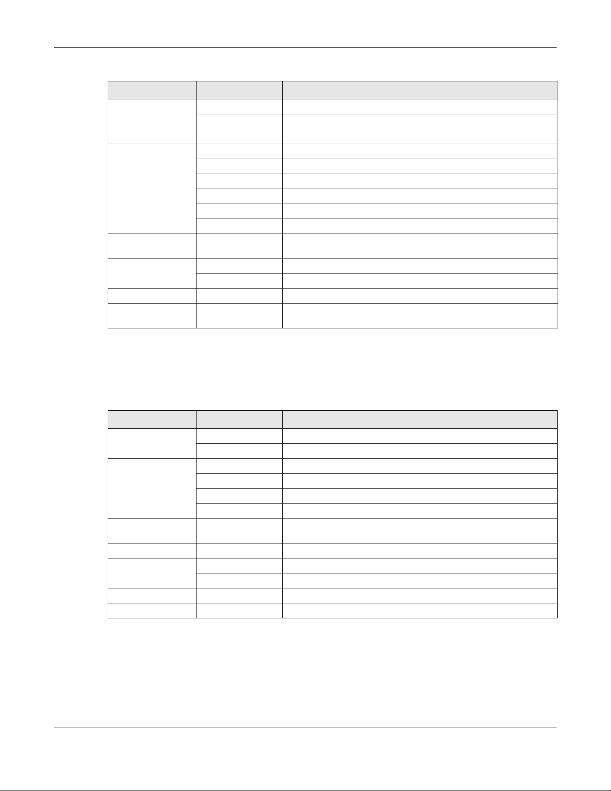
Chapter 5 Web Configurator
Table 10 Configuration Menu Screens Summary (continued)
FOLDER OR LINK TAB FUNCTION
Syslog Global Configure global settings.
Local Configure local settings.
Remote Configure remote settings.
SNMP Global Configure global settings.
Community Configure community settings.
Group Configure group settings.
User Configure users settings.
Trap Configure trap settings.
Trap Destination Configure trap destination settings.
Error Disable This link takes you to a screen where you can configure CPU
protection and error disable recovery.
HTTP/HTTPS HTTP Configure HTTP settings.
HTTPS Configure HTTPS settings.
Users Configure users settings.
Remote Access
Control
This link takes you to a screen where you can configure global and
profile settings.
Maintenance Menu
Use the maintenance menu screens to manage configuration and firmware files, run diagnostics, and
reboot or shut down the Switch.
Table 11 Maintenance Menu Screens Summary
FOLDER OR LINK TAB FUNCTION
Firmware Upload Manage upload settings.
Management Manage dual image and images information.
Configuration Backup Manage backup configuration.
Restore Manage restore configuration.
Management Manage configuration settings.
Factory Default Restore factory defaults.
Diagnostics This link takes you to screens where you can view system logs and can
Port Test Manage cable diagnosis and test results.
PING IPv4 Manage ping test settings.
IPv6 Manage IPv6 ping test settings.
Trace Manage trace route settings.
Reboot Reset the system.
test port(s).
GS1900 Series User’s Guide
51

6.1 Overview
A
Use the Getting Start screens to check status information about the Switch.
6.1.1 What You Can Do in this Chapter
• The main Getting Start screen (Section 6.2 on page 52) displays the Switch’s general device
information, system status, system resource usage, and interface status. You can also display other
status screens for more information.
6.2 Getting Start
CHAPTER 6
Getting Start
This screen is the first thing you see when you log into the Switch. It also appears every time you click the
Getting Start icon in the navigation panel. The Getting Start displays general device information, system
status, system resource usage, and interface status in widgets.
Figure 51 Getting Start
The following table describes the labels in this screen.
Table 12 Getting Start
LABEL DESCRIPTION
Refresh Interval (A) Use the drop-box to select: None, 5 seconds, 10 seconds, 15 seconds, 20 seconds, 25
seconds, or 30 seconds.
Virtual Device Displays an image of the Switch.
Wizard Displays the following links: Start up, VLAN, QoS, and Link aggregation.
Device Information
GS1900 Series User’s Guide
52

Table 12 Getting Start (continued)
LABEL DESCRIPTION
System Name This field displays the name used to identify the Switch on any network.
Model Name This field displays the model name of this Switch.
Revision This field displays the hardware revision number of this Switch.
Serial Number This field displays the serial number of this Switch.
MAC Address
Range
Firmware Version This field displays the version number and date of the firmware the Switch is currently
System Up Time This field displays how long the Switch has been running since it last restarted or was turned
Current Date/
Time
CPU Usage This field displays the Switch’s recent CPU usage.
Memory Usage This field displays the Switch’s recent memory usage.
6.2.1 Wizard
Chapter 6 Getting Start
This field displays the MAC addresses used by the Switch. Each physical port or wireless
radio has one MAC address. The first MAC address is assigned to the Ethernet LAN port, the
second MAC address is assigned to the first radio, and so on.
running.
on.
This field displays the current date and time in the Switch. The format is hh:mm:ss yyyy-mmdd.
Wizard displays start up, VLAN, QoS, and link aggregation.
For details on Wizard features, see system Chapter 7 on page 62, VLAN Chapter 9 on page 74, QoS
Chapter 29 on page 188, and link aggregation Chapter 11 on page 83.
Start up
In start up, you can set up IP/DNS, set up your username/password, and view finished results.
In order to set up your IP/DNS, please do the following. Click Getting Start > Start up > 1 Step 1 Set up IP to
access this screen.
Figure 52 Getting Start > Start up > 1 Step 1 Set up IP
GS1900 Series User’s Guide
53

Chapter 6 Getting Start
Each field is described in the following table.
Table 13 Getting Start > Start up > 1 Step 1 Set up IP
LABEL DESCRIPTION
Host Name This field displays a host name.
IP Address The Switch needs an IP address for it to be managed over the network. The factory default
Subnet Mask The subnet mask specifies the network number portion of an IP address.
Gateway Type the IP address of the default outgoing gateway in dotted decimal notation, for
DNS DNS (Domain Name System) is for mapping a domain name to its corresponding IP address
NTP (Network Time
Protocol)
Next Click Next to show the next screen.
IP address is 192.168.1.1.
The factory default subnet mask is 255.255.255.0.
example 192.168.1.254.
and vice versa. Enter a domain name server IP address in order to be able to use a domain
name instead of an IP address.
This field displays the NTP time servers from which the Switch gets the time and date.
After clicking Next, the set up your user name screen appears.
Figure 53 Getting Start > Start up > 2 Step 2 Set up user name/password
Each field is described in the following table.
Table 14 Getting Start > Start up > 2 Step 2 Set up user name/password
LABEL DESCRIPTION
Username The default username is admin and associated default password is 1234.
Password The default username is admin and associated default password is 1234.
Previous Click Previous to show the previous screen.
Next Click Next to show the next screen.
After clicking Next, the finish screen appears.
GS1900 Series User’s Guide
54
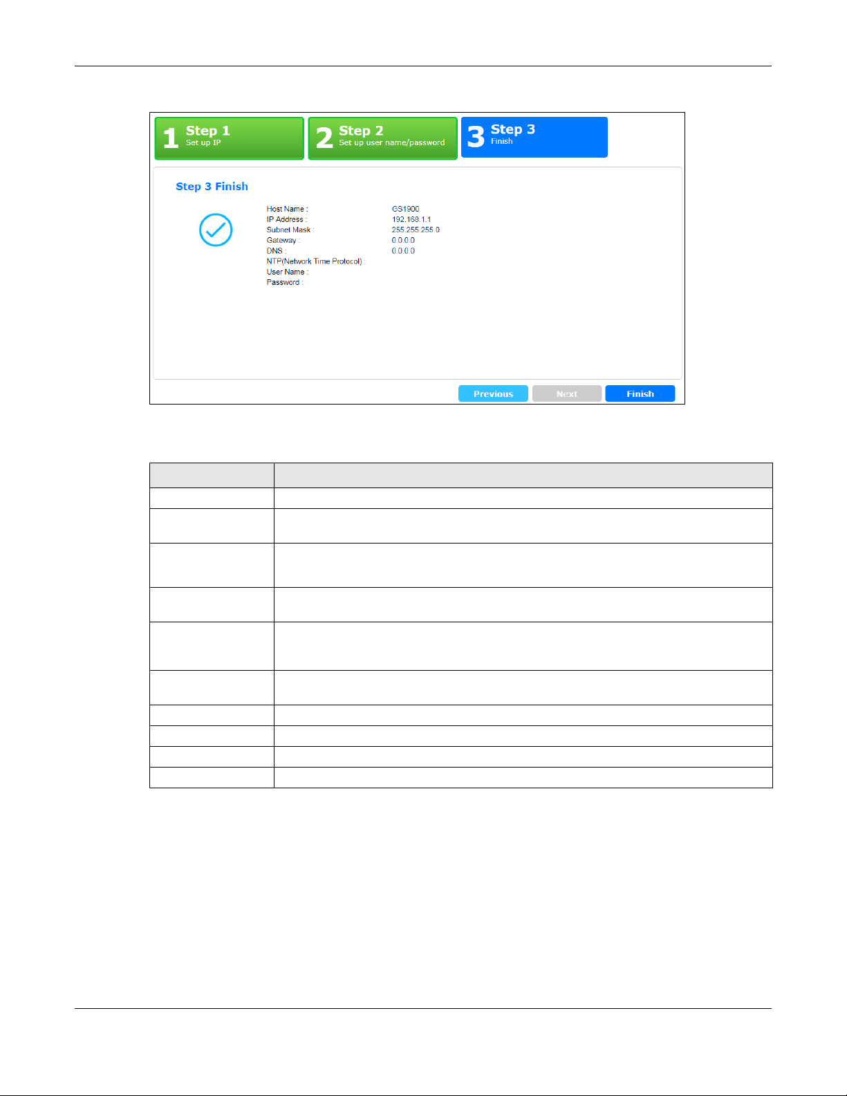
Chapter 6 Getting Start
Figure 54 Getting Start > Start up > 3 Step 3 Finish
Each field is described in the following table.
Table 15 Getting Start > Start up > 3 Step 3 Finish
LABEL DESCRIPTION
Host Name This field displays a host name.
IP Address The Switch needs an IP address for it to be managed over the network. The factory default
Subnet Mask The subnet mask specifies the network number portion of an IP address.
IP address is 192.168.1.1.
The factory default subnet mask is 255.255.255.0.
Gateway Type the IP address of the default outgoing gateway in dotted decimal notation, for
DNS DNS (Domain Name System) is for mapping a domain name to its corresponding IP address
NTP (Network Time
Protocol)
Username The default username is admin and associated default password is 1234.
Password The default username is admin and associated default password is 1234.
Previous Click Previous to show the previous screen.
Finish Review the information and click Finish to create the task.
example 192.168.1.254.
and vice versa. Enter a domain name server IP address in order to be able to use a domain
name instead of an IP address.
This field displays the NTP time servers from which the Switch gets the time and date.
VLAN
In VLAN, you can create VLAN, tag VLAN setting, and view finished results.
In order to create VLAN, please do the following. Click Getting Start > VLAN > 1 Step 1 Create VLAN to
access this screen.
GS1900 Series User’s Guide
55

Chapter 6 Getting Start
Figure 55 Getting Start > VLAN > 1 Step 1 Create VLAN
Each field is described in the following table.
Table 16 Getting Start > VLAN > 1 Step 1 Create VLAN
LABEL DESCRIPTION
Create VLAN ID (1-
4094)
Edit VLAN ID Select from the drop-box a VLAN ID.
Next Click Next to show the next screen.
Type a number between 1 and 4094 to create a VLAN ID.
After clicking Next, the tag VLAN setting screen appears.
Figure 56 Getting Start > VLAN > 2 Step 2 Tag VLAN Setting
GS1900 Series User’s Guide
56

Chapter 6 Getting Start
Each field is described in the following table.
Table 17 Getting Start > VLAN > 2 Step 2 Tag VLAN Setting
LABEL DESCRIPTION
Currently VLAN ID This field displays the VLAN identification number.
Tag Ports belonging to the specified VLAN tag all outgoing frames transmitted.
Untag Ports belonging to the specified VLAN do not tag all outgoing frames transmitted.
Previous Click Previous to show the previous screen.
Next Click Next to show the next screen.
After clicking Next, the finish screen appears.
Figure 57 Getting Start > VLAN> 3 Step 3 Finish
Each field is described in the following table.
Table 18 Getting Start > VLAN > 3 Step 3 Finish
LABEL DESCRIPTION
Currently VLAN ID This field displays the VLAN identification number.
Tag Ports belonging to the specified VLAN tag all outgoing frames transmitted.
Untag Ports belonging to the specified VLAN do not tag all outgoing frames transmitted.
Previous Click Previous to show the previous screen.
Finish Review the information and click Finish to create the task.
QoS
In QoS, you can create QoS settings, and view finished results.
In order to create QoS settings, please do the following. Click Getting Start > QoS > 1 Step 1 QoS (Quality
of Service) to access this screen.
GS1900 Series User’s Guide
57
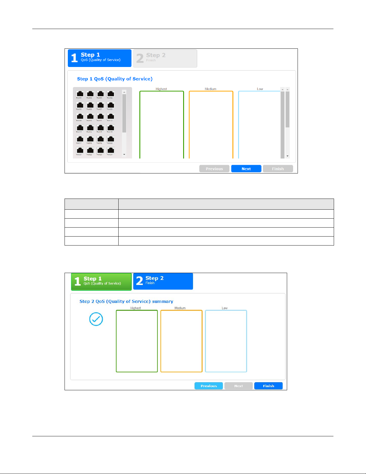
Chapter 6 Getting Start
Figure 58 Getting Start > QoS > 1 Step 1 QoS (Quality of Service)
Each field is described in the following table.
Table 19 Getting Start > QoS > 1 Step 1 QoS (Quality of Service)
LABEL DESCRIPTION
Highest Click and drag icons located on the left to desired preference.
Medium Click and drag icons located on the left to desired preference.
Low Click and drag icons located on the left to desired preference.
Next Click Next to show the next screen.
After clicking Next, the finish screen appears.
Figure 59 Getting Start > QoS > 2 Step 2 Finish
GS1900 Series User’s Guide
58

Chapter 6 Getting Start
Each field is described in the following table.
Table 20 Getting Start > QoS > 2 Step 2 Finish
LABEL DESCRIPTION
Highest Displays summary results.
Medium Displays summary results.
Low Displays summary results.
Previous Click Previous to show the previous screen.
Finish Review the information and click Finish to create the task.
Link Aggregation
In link aggregation, you can link aggregation and view finished results.
In order to create link aggregation settings, please do the following. Click Getting Start > Link
aggregation > 1 Step 1 Link aggregation to access this screen.
Figure 60 Getting Start > Link aggregation > 1 Step 1 Link aggregation
Each field is described in the following table.
Table 21 Getting Start > Link aggregation > 1 Step 1 Link aggregation
LABEL DESCRIPTION
Group 1 Click and drag icons located on the left to desired preference.
Group 2 Click and drag icons located on the left to desired preference.
Group 3 Click and drag icons located on the left to desired preference.
Group 4 Click and drag icons located on the left to desired preference.
Group 5 Click and drag icons located on the left to desired preference.
Group 6 Click and drag icons located on the left to desired preference.
Group 7 Click and drag icons located on the left to desired preference.
Group 8 Click and drag icons located on the left to desired preference.
Next Click Next to show the next screen.
GS1900 Series User’s Guide
59

Chapter 6 Getting Start
After clicking Next, the finish screen appears.
Figure 61 Getting Start > Link aggregation > 2 Step 2 Finish
Each field is described in the following table.
Table 22 Getting Start > Link aggregation > 2 Step 2 Finish
LABEL DESCRIPTION
Group 1 Displays summary results.
Group 2 Displays summary results.
Group 3 Displays summary results.
Group 4 Displays summary results.
Group 5 Displays summary results.
Group 6 Displays summary results.
Group 7 Displays summary results.
Group 8 Displays summary results.
Previous Click Previous to show the previous screen.
Finish Review the information and click Finish to create the task.
GS1900 Series User’s Guide
60

PART II
Technical Reference
61

Monitor: System
7.1 Overview
This section provides information for System in Monitor. Use the System screens to view general Switch
settings.
7.1.1 What You Can Do in this Chapter
•The IP screen (Section 7.2 on page 62) displays IPv4 and IPv6.
• The Information screen (Section 7.3 on page 63) displays the system information.
7.2 IP
CHAPTER 7
The Switch needs an IP address for it to be managed over the network. The factory default IP address is
192.168.1.1. The subnet mask specifies the network number portion of an IP address. The factory default
subnet mask is 255.255.255.0.
7.2.1 IPv4
Use this screen to view the Switch’s IPv4 information. Click Monitor > System > IP > IPv4 to open this
screen.
Figure 62 Monitor > System > IP > IPv4
The following table describes the labels in this screen.
Table 23 Monitor > System > IP > IPv4
LABEL DESCRIPTION
DHCP State This field displays the state of Dynamic Host Configuration Protocol RFC 2131 and RFC 2132
IP Address This field displays IP address of the Switch in the IP domain.
(DHCP).
GS1900 Series User’s Guide
62

Table 23 Monitor > System > IP > IPv4 (continued)
LABEL DESCRIPTION
Subnet Mask This field displays the subnet mask of the Switch in the IP domain.
Gateway This field displays the IP address of the default outgoing gateway in dotted decimal notation, for
DNS Server 1 DNS (Domain Name System) is for mapping a domain name to its corresponding IP address and
DNS Server 2 DNS (Domain Name System) is for mapping a domain name to its corresponding IP address and
Management
VLAN
7.2.2 IPv6
Use this screen to view the Switch’s IPv6 information. Click Monitor > System > IP > IPv6 to open this
screen.
Figure 63 Monitor > System > IP > IPv6
Chapter 7 Monitor: System
example 192.168.1.254.
vice versa. This field displays a domain name server IP address, enabling the use of a domain.
vice versa. This field displays a domain name server IP address, enabling the use of a domain.
This field displays the management VLAN.
The following table describes the labels in this screen.
Table 24 Monitor > System > IP > IPv6
LABEL DESCRIPTION
Auto
Configuration
IPv6 Address This field displays IP address of the Switch in the IP domain.
IPv6 Gateway This field displays the IP address of the default outgoing gateway.
DHCPv6 Client This field displays the Switch’s DHCP settings when it is acting as a DHCPv6 client.
7.3 Information
In the navigation panel, click Monitor > System > Information > System Information to display the screen
as shown. You can view system information.
Figure 64 Monitor > System > Information > System Information
This field displays auto configuration.
GS1900 Series User’s Guide
63

Chapter 7 Monitor: System
The following table describes the labels in this screen.
Table 25 Monitor > System > Information > System Information
LABEL DESCRIPTION
System Name This field displays the descriptive name of the Switch for identification purposes.
System Location This field displays the geographic location of the Switch for identification purposes.
System Contact This field displays the person in charge of the Switch for identification purposes.
GS1900 Series User’s Guide
64

8.1 Overview
This section provides information for Port in Monitor. Use the Port screens to view general Switch port
settings.
8.1.1 What You Can Do in this Chapter
•The Port screen (Section 8.2 on page 65) displays status, port counters, and bandwidth utilization.
• The PoE screen (Section 8.3 on page 69) displays PoE.
• The Bandwidth Management screen (Section 8.4 on page 71) displays bandwidth control.
• The Storm Control screen (Section 8.5 on page 72) displays port settings of the Switch.
CHAPTER 8
Monitor: Port
8.2 Port
Use this screen to view Switch port settings.
8.2.1 Status
Use this screen to view the Switch’s port statistics. Click Monitor > Port > Port > Status to access this screen.
Figure 65 Monitor > Port > Port > Status
GS1900 Series User’s Guide
65

Each field is described in the following table.
Table 26 Monitor > Port > Port > Status
LABEL DESCRIPTION
Port This is the port index number.
Port Name A descriptive name that identifies this port.
State This is port admin setting state.
Link Status This field displays Up, Down or Not Present. It displays Up when the port is linked up or Down
Speed View the speed of the Ethernet connection on this port.
Duplex View the duplex mode of the Ethernet connection on this port.
FlowCtrl Status A concentration of traffic on a port decreases port bandwidth and overflows buffer
Type View the type on this port.
8.2.2 Port Counters
Use this screen to view the Switch’s port counters settings. Click Monitor > Port > Port > Port Counters to
access this screen.
Chapter 8 Monitor: Port
when it is not. When no any physical port is binding with this group, it displays Not Present.
memory causing packet discards and frame losses. Flow Control is used to regulate
transmission of signals to match the bandwidth of the receiving port.
Figure 66 Monitor > Port > Port > Port Counters (Port 1 Interface mib Counters)
GS1900 Series User’s Guide
66

Chapter 8 Monitor: Port
Figure 67 Monitor > Port > Port > Port Counters (Port 1 Etherlike mib Counters)
Figure 68 Monitor > Port > Port > Port Counters (Port 1 RMON mib Counters)
Each field is described in the following table.
Table 27 Monitor > Port > Port > Port Counters
LABEL DESCRIPTION
Port Counters
Port This field displays the port.
Mode This field displays the mode.
Port 1 Interface mib Counters
iflnOctets This field displays the iflnOctets.
iflnUcastPkts This field displays the iflnUcastPkts.
iflnNUcastPkts This field displays the iflnNUcastPkts.
ifInDiscards This field displays the ifInDiscards.
ifOutOctets This field displays the ifOutOctets.
ifOutUcastPkts This field displays the ifOutUcastPkts.
ifOutNUcastPkts This field displays the ifOutNUcastPkts.
ifOutDiscards This field displays the ifOutDiscards.
ifInMulticastPkts This field displays the ifInMulticastPkts.
ifInBroadcastPkts This field displays the ifInBroadcastPkts.
GS1900 Series User’s Guide
67

Chapter 8 Monitor: Port
Table 27 Monitor > Port > Port > Port Counters (continued)
LABEL DESCRIPTION
ifOutMulticastPkts This field displays the ifOutMulticastPkts.
ifOutBroadcastPkts This field displays the ifOutBroadcastPkts.
Port 1 Etherlike mib Counters
dot3StatsAlignmentErrors This field displays the dot3StatsAlignmentErrors.
dot3StatsFCSErrors This field displays the dot3StatsFCSErrors.
dot3StatsSingleCollisionFrames This field displays the dot3StatsSingleCollisionFrames.
dot3StatsMultipleCollisionFrames This field displays the dot3StatsMultipleCollisionFrames.
dot3StatsDeferredTransmissions This field displays the dot3StatsDeferredTransmissions.
dot3StatsLateCollisions This field displays the dot3StatsLateCollisions.
dot3StatsExcessiveCollisions This field displays the dot3StatsExcessiveCollisions.
dot3StatsFrameTooLongs This field displays the dot3StatsFrameTooLongs.
dot3StatsSymbolErrors This field displays the dot3StatsSymbolErrors.
dot3ControlInUnkownOpcodes This field displays the dot3ControlInUnkownOpcodes.
dot3lInPauseFrames This field displays the dot3lInPauseFrames.
dot3lOutPauseFrames This field displays the dot3lOutPauseFrames.
Port 1 RMON mib Counters
etherStatsDropEvents This field displays the etherStatsDropEvents.
etherStatsOctets This field displays the etherStatsOctets.
etherStatsPkts This field displays the etherStatsPkts.
etherStatsBroadcastPkts This field displays the etherStatsBroadcastPkts.
etherStatsMulticastPkts This field displays the etherStatsMulticastPkts.
etherStatsCRCAlignErrors This field displays the etherStatsCRCAlignErrors.
etherStatsUnderSizePkts This field displays the etherStatsUnderSizePkts.
etherStatsOverSizePkts This field displays the etherStatsOverSizePkts.
etherStatsFragments This field displays the etherStatsFragments.
etherStatsJabbers This field displays the etherStatsJabbers.
etherStatsCollisions This field displays the etherStatsCollisions.
etherStatsPkts64Octets This field displays the etherStatsPkts64Octets.
etherStatsPkts65to127Octets This field displays the etherStatsPkts65to127Octets.
etherStatsPkts128to255Octets This field displays the etherStatsPkts128to255Octets.
etherStatsPkts256to511Octets This field displays the etherStatsPkts256to511Octets.
etherStatsPkts512to1023Octets This field displays the etherStatsPkts512to1023Octets.
etherStatsPkts1024to1518Octets This field displays the etherStatsPkts1024to1518Octets.
8.2.3 Bandwidth Utilization
Utilization is the percentage of a network's bandwidth that is currently being consumed by network
traffic. Each vertical bar represents the highest utilization on a port, and can be either transmitted (Tx)
traffic or received (Rx) traffic during the last time interval in seconds.
Use this screen to view the Switch’s bandwidth utilization settings. Click Monitor > Port > Port > Bandwidth
Utilization to access this screen.
GS1900 Series User’s Guide
68

Chapter 8 Monitor: Port
Figure 69 Monitor > Port > Port > Bandwidth Utilization
Each field is described in the following table.
Table 28 Monitor > Port > Port > Bandwidth Utilization
LABEL DESCRIPTION
Bandwidth Utilization
8.3 PoE
Note: The PoE function and the following screens are available for models ending in “HP”
The Switch supports both the IEEE 802.3af Power over Ethernet (PoE) and IEEE 802.3at High Power over
Ethernet (PoE) standards. The Switch is Power Sourcing Equipment (PSE) because it provides a source of
power via its Ethernet ports, and each device that receives power through an Ethernet port is a
1Gbps This field displays the 1Gbps.
100Mbps This field displays the 100Mbps.
10Mbps This field displays the 10Mbps.
Link down This field displays the link down.
Refresh period This field displays the refresh period.
IFG This field displays the IFG.
Tx Transmitted (Tx) traffic during the last time interval in seconds.
Rx Received (Rx) traffic during the time interval in seconds.
only.
GS1900 Series User’s Guide
69

Chapter 8 Monitor: Port
Powered Device (PD).
In the figure below, the IP camera and IP phone get their power directly from the Switch. Aside from
minimizing the need for cables and wires, PoE removes the hassle of trying to find a nearby electric
outlet to power up devices.
Figure 70 Powered Device Examples
You can also set priorities so that the Switch is able to reserve and allocate power to certain PDs.
Note: The PoE devices that supply or receive power and their connected Ethernet cables
must all be completely indoors.
To view the current amount of power that PDs are receiving from the Switch, click Monitor > Port > PoE.
Figure 71 Monitor > Port > PoE
Each field is described in the following table.
Table 29 Monitor > Port > PoE
LABEL DESCRIPTION
PoE Mode This field displays the power management mode used by the Switch, whether it is in
Classification or Consumption mode.
Total Power(W) This field displays the total power the Switch can provide to the connected PoE-enabled
devices on the PoE ports. The total power of GS1900-10HP is 77W and GS1900-8HP is 70W.
Consuming
Power(W)
Allocated Power(W) This field displays the total amount of power the Switch (in Classification mode) has
Remaining Power(W) This field displays the amount of power the Switch can still provide for PoE.
This field displays the total amount of power the Switch is currently supplying to the
connected PoE-enabled devices.
reserved for PoE after negotiating with the connected PoE device(s). It shows NA when the
Switch is in Consumption mode.
Consuming Power (W) can be less than or equal but not more than the Allocated Power
(W).
Note: The Switch must have at least 16 W of remaining power in order to supply power to a
PoE device, even if the PoE device needs less than 16 W.
GS1900 Series User’s Guide
70

Chapter 8 Monitor: Port
8.4 Bandwidth Management
This section shows you the maximum bandwidth using the Bandwidth Management screen. Bandwidth
management shows the maximum allowable bandwidth for incoming and/or out-going traffic flows on
a port.
8.4.1 Bandwidth Control
Use this screen to view the Switch’s bandwidth control in egress global burst and port rate.
An egress port is an outgoing port, that is, a port through which a data packet leaves for both ports. An
ingress port is an incoming port, that is, a port through which a data packet enters.
Click Monitor > Port > Bandwidth Management > Bandwidth Control to access this screen.
Figure 72 Monitor > Port > Bandwidth Management > Bandwidth Control
Each field is described in the following table.
Table 30 Monitor > Port > Bandwidth Management > Bandwidth Control
LABEL DESCRIPTION
Bandwidth Control
Egress Global
Burst
Port Rate View the maximum bandwidth allowed in kilobits per second (Kbps) for the traffic flow on a
Port This field displays the port number.
This field specifies the current egress burst size in bytes all ports.
port.
GS1900 Series User’s Guide
71

Table 30 Monitor > Port > Bandwidth Management > Bandwidth Control (continued)
LABEL DESCRIPTION
Ingress RateLimit
(Kbps)
Egress RateLimit
(Kbps)
8.5 Storm Control
This section shows you the storm control feature.
Storm control limits the number of broadcast, multicast and unicast packets the Switch receives per
second on the ports. When the maximum number of allowable broadcast, multicast and/or unicast
packets is reached per second, the subsequent packets are discarded. Enabling this feature reduces
broadcast, multicast and/or unicast packets in your network. You can specify limits for each packet
type on each port.
Click Monitor > Port > Storm Control to access this screen.
Chapter 8 Monitor: Port
View the maximum bandwidth allowed in kilobits per second (Kbps) for the incoming traffic
flow on a port.
View the maximum bandwidth allowed in kilobits per second (Kbps) for the out-going traffic
flow on a port.
Figure 73 Monitor > Port > Storm Control
GS1900 Series User’s Guide
72

Chapter 8 Monitor: Port
Each field is described in the following table.
Table 31 Monitor > Port > Storm Control
LABEL DESCRIPTION
Storm Control
Port This field displays the port number.
State This field displays the state.
Broadcast (pps) Displays how many broadcast packets the port receives (in pps).
Unknown
Multicast (pps)
Unknown Unicast
(pps)
Action Displays the action the device takes when a limit is reached. The following options are
Displays how many unknown multicast packets the port receives (in pps).
Displays how many unknown unicast packets the port receives (in pps).
available:
• Drop - drop the packet.
• Shutdown - shutdown the connection.
GS1900 Series User’s Guide
73

9.1 Overview
This section provides information for VLAN in Monitor.
A VLAN (Virtual Local Area Network) allows a physical network to be partitioned into multiple logical
networks. Devices on a logical network belong to one group. A device can belong to more than one
group. With VLAN, a device cannot directly talk to or hear from devices that are not in the same
group(s); the traffic must first go through a router.
In MTU (Multi-Tenant Unit) applications, VLAN is vital in providing isolation and security among the
subscribers. When properly configured, VLAN prevents one subscriber from accessing the network
resources of another on the same LAN, thus a user will not see the printers and hard disks of another user
on the same network.
VLAN also increases network performance by limiting broadcasts to a smaller and more manageable
logical broadcast domain. In traditional switched environments, all broadcast packets go to each and
every individual port. With VLAN, all broadcasts are confined to a specific broadcast domain.
CHAPTER 9
Monitor: VLAN
9.1.1 What You Can Do in this Chapter
•The VLAN screen (Section 9.2 on page 74) displays VLAN, port, and VLAN port settings.
• The Guest VLAN screen (Section 9.3 on page 77) displays the global and port settings of the Switch.
• The Voice VLAN screen (Section 9.4 on page 78) displays the global and port settings of the Switch.
9.2 VLAN
Use this screen to view Switch VLAN settings.
9.2.1 VLAN
Use this screen to view the Switch’s VLAN settings. Click Monitor > VLAN > VLAN > VLAN to access this
screen.
Figure 74 Monitor > VLAN > VLAN > VLAN
GS1900 Series User’s Guide
74

Each field is described in the following table.
Table 32 Monitor > VLAN > VLAN > VLAN
9.2.2 Port
Use this screen to view the Switch’s port setting in VLAN. Click Monitor > VLAN > VLAN > Port to access
this screen.
Figure 75 Monitor > VLAN > VLAN > Port
Chapter 9 Monitor: VLAN
LABEL DESCRIPTION
VLAN
VLAN ID This is the VLAN identification number.
VLAN Name Displays a descriptive name for the VLAN for identification purposes.
VLAN Type Displays a type for the VLAN for identification purposes.
Each field is described in the following table.
Table 33 Monitor > VLAN > VLAN > Port
LABEL DESCRIPTION
Port
Port This field displays the port number.
PVID This is the port VLAN identification number.
A PVID (Port VLAN ID) is a tag that adds to incoming untagged frames received on a port
so that the frames are forwarded to the VLAN group that the tag defines.
GS1900 Series User’s Guide
75

Table 33 Monitor > VLAN > VLAN > Port (continued)
LABEL DESCRIPTION
Accept Frame
Type
Ingress Filter If set, the Switch discards incoming frames for VLANs that do not have this port as a
VLAN Trunks Enable VLAN Trunking on ports connected to other switches or routers (but not ports directly
9.2.3 VLAN Port
Port-based VLANs are VLANs where the packet forwarding decision is based on the destination MAC
address and its associated port. Port-based VLANs require allowed outgoing ports to be defined for
each port. Therefore, if you wish to allow two subscriber ports to talk to each other, for example,
between conference rooms in a hotel, you must define the egress (an egress port is an outgoing port,
that is, a port through which a data packet leaves) for both ports. Port-based VLANs are specific only to
the Switch on which they were created.
Chapter 9 Monitor: VLAN
This field displays the type that is accepted by the frame.
Specifies the type of frames allowed on a port. Choices are All, Tag Only and Untag Only.
All accepts all untagged or tagged frames on this port. This is the default setting. Tag Only
accepts only tagged frames on this port. All untagged frames will be dropped. Untag Only
accepts only untagged frames on this port. All tagged frames will be dropped.
member.
connected to end users) to allow frames belonging to unknown VLAN groups to pass
through the Switch.
Use this screen to view the Switch’s VLAN port settings. Click Monitor > VLAN > VLAN > VLAN Port to
access this screen.
Figure 76 Monitor > VLAN > VLAN > VLAN Port
GS1900 Series User’s Guide
76

Each field is described in the following table.
Table 34 Monitor > VLAN > VLAN > VLAN Port
LABEL DESCRIPTION
VLAN Port
VLAN ID This is the VLAN identification number.
Port Displays the port index value.
Membership Displays the status of the VLAN group: Forbidden, Excluded, Tagged or Untagged.
9.3 Guest VLAN
When 802.1x port authentication is enabled on the Switch and its ports, clients that do not have the
correct credentials are blocked from using the port(s). You can configure your Switch to have one VLAN
that acts as a guest VLAN. If you enable the guest VLAN (102 in the example) on a port (2 in the
example), the user (A in the example) that is not IEEE 802.1x capable or fails to enter the correct
username and password can still access the port, but traffic from the user is forwarded to the guest
VLAN. That is, unauthenticated users can have access to limited network resources in the same guest
VLAN, such as the Internet. The rights granted to the Guest VLAN depends on how the network
administrator configures switches or routers with the guest network feature.
Chapter 9 Monitor: VLAN
Figure 77 Guest VLAN Example
Use this screen to view the Switch’s guest VLAN. Click Monitor > VLAN > Guest VLAN to access this
screen.
GS1900 Series User’s Guide
77

Chapter 9 Monitor: VLAN
Figure 78 Monitor > VLAN > Guest VLAN
Each field is described in the following table.
Table 35 Monitor > VLAN > Guest VLAN
LABEL DESCRIPTION
Guest VLAN
State This field displays the state of global guest VLAN.
Port
Port This field displays a port number.
State This field displays the state of a port.
In Guest VLAN This field displays the status of the port, is the port is in guest VLAN or not.
9.4 Voice VLAN
Voice VLANs are VLANs configured specially for voice traffic. By adding the ports connected with voice
devices to voice VLANs, you can have voice traffic transmitted within voice VLANs and perform QoSrelated configuration for voice traffic as required, thus ensuring the transmission priority of voice traffic
and voice quality.
Use this screen to view Switch global and port voice VLAN settings for voice traffic. Click Monitor > VLAN
> Voice VLAN to access this screen.
GS1900 Series User’s Guide
78

Chapter 9 Monitor: VLAN
Figure 79 Monitor > VLAN > Voice VLAN
Each field is described in the following table.
Table 36 Monitor > VLAN > Voice VLAN
LABEL DESCRIPTION
Voice VLAN
State This field displays the state of a port.
Voice VLAN ID This is the voice VLAN identification number.
Cos/802.1p This displays the packet’s 802.1p priority field.
Remark Cos/802.1p This field displays the state of the cos/802.1p.
Aging Time (30-65536 min) Displays the time interval (from 30 to 65536) in minutes.
Port
Port This field displays a port number.
State This field displays the state of a port.
GS1900 Series User’s Guide
79

10.1 Overview
This section provides information for MAC Table in Monitor.
The MAC Table screen (a MAC table is also known as a filtering database) shows how frames are
forwarded or filtered across the Switch’s ports. When a device (which may belong to a VLAN group)
sends a packet which is forwarded to a port on the Switch, the MAC address of the device is shown on
the Switch’s MAC Table. It also shows whether the MAC address is dynamic (learned by the Switch) or
static (manually entered in the Static MAC Forwarding screen).
The Switch uses the MAC Table to determine how to forward frames. See the following figure.
1 The Switch examines a received frame and learns the port from which this source MAC address came.
2 The Switch checks to see if the frame's destination MAC address matches a source MAC address
already learned in the MAC Table.
• If the Switch has already learned the port for this MAC address, then it forwards the frame to that port.
• If the Switch has not already learned the port for this MAC address, then the frame is flooded to all
ports. Too much port flooding leads to network congestion.
• If the Switch has already learned the port for this MAC address, but the destination port is the same as
the port it came in on, then it filters the frame.
Figure 80 MAC Table Flowchart
CHAPTER 10
Monitor: MAC Table
This link takes you to a screen where you can view the MAC address and VLAN ID of a device attach to
a port. You can also view what kind of MAC address it is.
GS1900 Series User’s Guide
80

Chapter 10 Monitor: MAC Table
10.1.1 What You Can Do in this Chapter
•The MAC Table screen (Section 10.2 on page 81) displays view filter and MAC table of the Switch.
10.2 MAC Table
Use this screen to view filter static and MAC table settings. Click Monitor > MAC Table to access this
screen.
Figure 81 Monitor > MAC Table
Each field is described in the following table.
Table 37 Monitor > MAC Table
LABEL DESCRIPTION
MAC Table
MAC Address This is the MAC address of the device from which this incoming frame came.
VLAN Displays a type for the VLAN for identification purposes.
Port This is the port from which the above MAC address was learned.
View This link takes you to a screen where you can view the MAC address and VLAN ID of a
device attach to a port. You can also view what kind of MAC address it is.
Clear Click Clear to return the fields to the factory defaults.
MAC Address This is the MAC address of the device from which this incoming frame came.
VLAN Displays a type for the VLAN for identification purposes.
GS1900 Series User’s Guide
81

Chapter 10 Monitor: MAC Table
Table 37 Monitor > MAC Table (continued)
LABEL DESCRIPTION
Type This shows whether the MAC address is dynamic (learned by the Switch) or static (manually
entered in the Static MAC Forwarding screen).
Port This is the port from which the above MAC address was learned.
Total Entries Displays the number of total entries.
GS1900 Series User’s Guide
82

Monitor: Link Aggregation
11.1 Overview
This section provides information for Link Aggregation in Monitor.
Link aggregation (trunking) is the grouping of physical ports into one logical higher-capacity link. You
may want to trunk ports if for example, it is cheaper to use multiple lower-speed links than to under-utilize
a high-speed, but more costly, single-port link. However, the more ports you aggregate then the fewer
available ports you have. A trunk group is one logical link containing multiple ports.
The Switch supports both static and dynamic link aggregation.
Note: In a properly planned network, it is recommended to implement static link aggregation
only. This ensures increased network stability and control over the trunk groups on your
Switch.
CHAPTER 11
11.1.1 What You Can Do in this Chapter
•The Link Aggregation screen (Section 11.2 on page 83) displays link aggregation status.
11.2 Link Aggregation
Use the Link Aggregation screens to view Switch link aggregation status. Click Monitor > Link
Aggregation to access this screen.
Figure 82 Monitor > Link Aggregation
GS1900 Series User’s Guide
83

Chapter 11 Monitor: Link Aggregation
Each field is described in the following table.
Table 38 Monitor > Link Aggregation
LABEL DESCRIPTION
LAG Displays the link aggregation status index value.
Name This field displays the name.
Type This field displays the type.
Link Status This field displays the status of the link. It displays Up when the port is linked up or Down when
Active Member Displays if this member is an active member of a trunk.
Standby Member Displays if this member is an standby member of a trunk.
it is not. When no any physical port is binding with this group, it displays NotPresent.
GS1900 Series User’s Guide
84

12.1 Overview
This section provides information for Loop Guard in Monitor.
Loop guard is designed to handle loop problems on the edge of your network. This can occur when a
port is connected to a Switch that is in a loop state. Loop state occurs as a result of human error. It
happens when two ports on a switch are connected with the same cable. When a switch in loop state
sends out broadcast messages the messages loop back to the switch and are re-broadcast again and
again causing a broadcast storm.
If a switch (not in loop state) connects to a switch in loop state, then it will be affected by the switch in
loop state in the following way:
• It will receive broadcast messages sent out from the switch in loop state.
• It will receive its own broadcast messages that it sends out as they loop back. It will then re-broadcast
those messages again.
CHAPTER 12
Monitor: Loop Guard
The following figure shows port N on switch A connected to switch B. Switch B is in loop state. When
broadcast or multicast packets leave port N and reach switch B, they are sent back to port N on A as
they are rebroadcast from B.
Figure 83 Switch in Loop State
The loop guard feature checks to see if a loop guard enabled port is connected to a switch in loop
state. This is accomplished by periodically sending a probe packet and seeing if the packet returns on
the same port. If this is the case, the Switch will shut down the port connected to the switch in loop state.
The following figure shows a loop guard enabled port N on switch A sending a probe packet P to switch
B. Since switch B is in loop state, the probe packet P returns to port N on A. The Switch then shuts down
port N to ensure that the rest of the network is not affected by the switch in loop state.
GS1900 Series User’s Guide
85

Chapter 12 Monitor: Loop Guard
Figure 84 Loop Guard - Probe Packet
The Switch also shuts down port N if the probe packet returns to switch A on any other port. In other
words loop guard also protects against standard network loops. The following figure illustrates three
switches forming a loop. A sample path of the loop guard probe packet is also shown. In this example,
the probe packet is sent from port N and returns on another port. As long as loop guard is enabled on
port N. The Switch will shut down port N if it detects that the probe packet has returned to the Switch.
Figure 85 Loop Guard - Network Loop
12.1.1 What You Can Do in this Chapter
•The Loop Guard screen (Section 12.2 on page 86) displays loop guard status.
12.2 Loop Guard
Use the Loop Guard screen to view Switch loop guard status. Click Monitor > Loop Guard to access this
screen.
GS1900 Series User’s Guide
86

Chapter 12 Monitor: Loop Guard
Figure 86 Monitor > Loop Guard
Each field is described in the following table.
Table 39 Monitor > Loop Guard
LABEL DESCRIPTION
Loop Guard
Port This field displays a port number.
Status This field displays the status.
Time Left (sec) This field displays the amount of time left in seconds.
Action This field displays the action.
GS1900 Series User’s Guide
87

Monitor: Multicast
13.1 Overview
This section provides information for Multicast in Monitor.
Traditionally, IP packets are transmitted in one of either two ways - Unicast (1 sender to 1 recipient) or
Broadcast (1 sender to everybody on the network). Multicast delivers IP packets to just a group of hosts
on the network.
IGMP (Internet Group Management Protocol) is a network-layer protocol used to establish membership
in an IPv4 multicast group - it is not used to carry user data. Refer to RFC 1112, RFC 2236 and RFC 3376 for
information on IGMP versions 1, 2 and 3 respectively.
13.1.1 What You Can Do in this Chapter
CHAPTER 13
•The IGMP screen (Section 13.2 on page 88) displays Vlan, statistics, group, and router.
13.2 IGMP
Use this screen to view Switch various multicast features.
13.2.1 VLAN
Use this screen to view the Switch’s IGMP VLAN. Click Monitor > Multicast > IGMP > VLAN to access this
screen.
Figure 87 Monitor > Multicast > IGMP > VLAN
Each field is described in the following table.
Table 40 Monitor > Multicast > IGMP > VLAN
LABEL DESCRIPTION
IGMP Vlan
VLAN ID Displays the identification for the VLAN.
Operate Status Displays the status of the operation.
GS1900 Series User’s Guide
88

Chapter 13 Monitor: Multicast
Table 40 Monitor > Multicast > IGMP > VLAN (continued)
LABEL DESCRIPTION
Router Ports Auto
Learn
Query
Retry Displays the number of retry.
Interval Displays the number (in seconds) for the time interval.
Max. Response
Interval (sec)
Last Member Query
Count Displays the number of count.
Interval (sec) Displays the in seconds for the time interval.
Querier Allows the Switch to send IGMP General Query messages to the VLANs with the multicast
Status This field displays the entry as querier or non-querier.
Version This field displays the entry querier version.
IP This field displays the entry querier IP address.
Total Entries This field displays the number of total entries.
Displays whether the router ports are auto learn or not.
Displays the maximum response (in seconds) for the time interval.
hosts attached.
13.2.2 Statistics
Use this screen to view the Switch’s IGMP statistics. Click Monitor > Multicast > IGMP > Statistics to access
this screen.
Figure 88 Monitor > Multicast > IGMP > Statistics
Each field is described in the following table.
Table 41 Monitor > Multicast > IGMP > Statistics
LABEL DESCRIPTION
IGMP Statistics
Port This field displays a port number.
Total RX This field displays the total amount of RX.
GS1900 Series User’s Guide
89

Chapter 13 Monitor: Multicast
Table 41 Monitor > Multicast > IGMP > Statistics
LABEL DESCRIPTION
Valid RX This field displays the total amount of valid RX.
Invalid RX This field displays the total amount of invalid RX.
Other RX This field displays the total amount of other RX.
Leave RX This field displays the total amount of leave RX.
Report RX This field displays the total amount of report RX.
General Query RX This field displays the total amount of general query RX.
Group-Spec Query RX This field displays the total amount of group-spec query RX.
Source-Spec Query RX This field displays the total amount of source-spec query RX.
Leave TX This field displays the total amount of leave TX.
Report TX This field displays the total amount of report TX.
General Query TX This field displays the total amount of general query TX.
Group-Spec Query TX This field displays the total amount of group-spec query TX.
Source-Spec Query TX This field displays the total amount of source-spec query TX.
Action Click Action to reset the statistics of the specific field back to zero.
Clear Click Clear to clear statistics on this port.
Clear Click Clear to reset the fields to the factory defaults.
Refresh Click Refresh to reload the page.
In the Action column, the Action option allows you to clear the statistics.
Click OK and confirm at the pop-up screen to complete the task. Click Cancel and confirm at the popup screen to discard the changes.
Figure 89 Monitor > Multicast > IGMP > Statistics > Action
13.2.3 Group
Use this screen to view the Switch’s IGMP group. Click Monitor > Multicast > IGMP > Group to access this
screen.
Figure 90 Monitor > Multicast > IGMP > Group
GS1900 Series User’s Guide
90

Each field is described in the following table.
Table 42 Monitor > Multicast > IGMP > Group
LABEL DESCRIPTION
IGMP Group
VLAN ID Displays the identification for the VLAN.
Group IP Address This field displays the group IP address.
Member Ports This field displays the member ports.
Life(sec) Displays life in seconds for the time interval.
Total Entries This field displays the number of total entries.
Clear Click Clear to delete the dynamic groups.
Refresh Click Refresh to reload the page.
13.2.4 Router
Use this screen to view the Switch’s IGMP router. Click Monitor > Multicast > IGMP > Router to access this
screen.
Figure 91 Monitor > Multicast > IGMP > Router
Chapter 13 Monitor: Multicast
Each field is described in the following table.
Table 43 Monitor > Multicast > IGMP > Router
LABEL DESCRIPTION
IGMP Router
VLAN ID Displays the identification for the VLAN.
Dynamic Router Ports This field displays the dynamic router ports.
Static Router Ports This field displays the static router ports.
Forbidden Router Ports This field displays the forbidden router ports.
Total Entries This field displays the number of total entries.
GS1900 Series User’s Guide
91

Monitor: Spanning Tree
14.1 Overview
This section provides information for Spanning Tree in Monitor.
The Switch supports Spanning Tree Protocol (STP), Common and Internal Spanning Tree (CIST), and
Multiple Spanning Tree (MST).
14.1.1 What You Can Do in this Chapter
•The Spanning Tree screen (Section 14.2 on page 92) displays CIST, CIST port, MST, MST port, STP
statistics.
CHAPTER 14
14.2 Spanning Tree
Use this screen to view Switch spanning tree settings.
14.2.1 CIST
Use this screen to view the Switch’s spanning tree CIST instance. Click Monitor > Spanning Tree > CIST to
access this screen.
Figure 92 Monitor > Spanning Tree > CIST
Each field is described in the following table.
Table 44 Monitor > Spanning Tree > CIST
LABEL DESCRIPTION
CIST Instance
State This field displays the state.
GS1900 Series User’s Guide
92

Chapter 14 Monitor: Spanning Tree
Table 44 Monitor > Spanning Tree > CIST
LABEL DESCRIPTION
Bridge
Identifier
Designated
Root Bridge
External Root
Path Cost
Regional Root
Bridge
Internal Root
Path Cost
Designated
Bridge
Root Port On each bridge, the bridge communicates with the root through the root port. The root port is the
Remaining
Hops
Last Topology
Change
This is the unique identifier for this bridge, consisting of the bridge priority plus the MAC address.
Root bridge refers to the base of the spanning tree.
The cost of the path from this bridge to the cist Root Bridge.
Root bridge refers to the base of the spanning tree.
The cost of the path from this bridge to the internal Regional Root Bridge.
For each LAN segment, a designated bridge is selected. This bridge has the lowest cost to the root
among the bridges connected to the LAN.
port on this Switch with the lowest path cost to the root (the root path cost). If there is no root port,
then this Switch has been accepted as the root bridge of the spanning tree network.
This field displays the number of remaining hops.
Topology change information is directly propagated throughout the network from the device that
generates the topology change.
14.2.2 CIST Port
Use this screen to view the Switch’s spanning tree CIST port status. Click Monitor > Spanning Tree > CIST
Port to access this screen.
Figure 93 Monitor > Spanning Tree > CIST Port
Each field is described in the following table.
Table 45 Monitor > Spanning Tree > CIST Port
LABEL DESCRIPTION
Port This field displays the port number.
Identifier (Priority /
Port Id)
External Path Cost
Operation
This field displays the identifier (in priority / port number).
Path cost is the cost of transmitting a frame on to a LAN through that port. It is recommended
to assign this value according to the speed of the bridge. The slower the media, the higher
the cost.
GS1900 Series User’s Guide
93

Chapter 14 Monitor: Spanning Tree
Table 45 Monitor > Spanning Tree > CIST Port
LABEL DESCRIPTION
Internal Path Cost
Operation
Designated Root
Bridge
External Root Cost This field displays the external root cost.
Regional Root
Bridge
Internal Root Cost This field displays the internal root cost.
Designated Bridge For each LAN segment, a designated bridge is selected. This bridge has the lowest cost to the
Edge Port
Operation
P2P MAC
Operation
Port Role This field displays the state of the port role.
Port State This field displays the state of the port.
Path cost is the cost of transmitting a frame on to a LAN through that port. It is recommended
to assign this value according to the speed of the bridge. The slower the media, the higher
the cost.
Root bridge refers to the base of the spanning tree.
Root bridge refers to the base of the spanning tree.
root among the bridges connected to the LAN.
An edge port changes its initial STP port state from blocking state to forwarding state
immediately without going through listening and learning states right after the port is
configured as an edge port or when its link status changes.
This field displays the state of the P2P MAC operation.
14.2.3 MST
Use this screen to view the Switch’s spanning tree MST instance. Click Monitor > Spanning Tree > MST to
access this screen.
Figure 94 Monitor > Spanning Tree > MST
Each field is described in the following table.
Table 46 Monitor > Spanning Tree > MST
LABEL DESCRIPTION
MST Instance
MST ID This is the unique identifier for this MST.
State This field displays the state.
Regional Root Bridge Root bridge refers to the base of the spanning tree.
Internal Root Cost This field displays the internal root cost.
Designated Bridge For each LAN segment, a designated bridge is selected. This bridge has the lowest cost to
Select a number from the drop-down menu to display results.
the root among the bridges connected to the LAN.
GS1900 Series User’s Guide
94
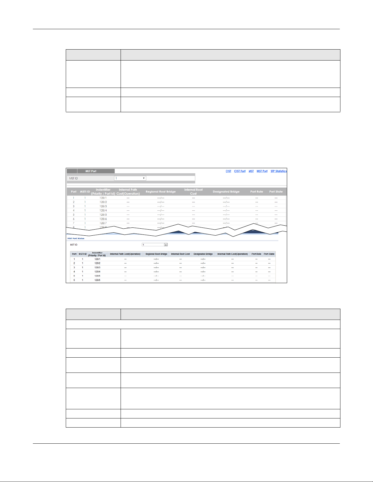
Table 46 Monitor > Spanning Tree > MST
LABEL DESCRIPTION
Root Port On each bridge, the bridge communicates with the root through the root port. The root port
Remaining Hops This field displays the number of remaining hops.
Last Topology
Change
14.2.4 MST Port
Use this screen to view the Switch’s spanning tree MST port status. Click Monitor > Spanning Tree > MST
Port to access this screen.
Figure 95 Monitor > Spanning Tree > MST Port
Chapter 14 Monitor: Spanning Tree
is the port on this Switch with the lowest path cost to the root (the root path cost). If there is
no root port, then this Switch has been accepted as the root bridge of the spanning tree
network.
Topology change information is directly propagated throughout the network from the
device that generates the topology change.
Each field is described in the following table.
Table 47 Monitor > Spanning Tree > MST Port
LABEL DESCRIPTION
MST Port
MST ID This is the unique identifier for this MST.
Select a number from the drop-down menu to display results.
Port This field displays the port number.
MSTI ID A VLAN can be mapped to a specific Multiple Spanning Tree Instance (MSTI). MSTI allows
Identifier (Priority /
Port Id)
Internal Path
Cost(Operation)
Regional Root Bridge Root bridge refers to the base of the spanning tree.
Internal Root Cost This field displays the internal root cost.
multiple VLANs to use the same spanning tree.
This field displays the identifier (in priority / port number).
Path cost is the cost of transmitting a frame on to a LAN through that port. It is
recommended to assign this value according to the speed of the bridge. The slower the
media, the higher the cost.
GS1900 Series User’s Guide
95

Table 47 Monitor > Spanning Tree > MST Port (continued)
LABEL DESCRIPTION
Designated Bridge For each LAN segment, a designated bridge is selected. This bridge has the lowest cost to
Port Role This field displays the state of the port role.
Port State This field displays the state of the port.
14.2.5 STP Statistics
(R)STP detects and breaks network loops and provides backup links between switches, bridges or
routers. It allows a Switch to interact with other (R)STP-compliant switches in your network to ensure that
only one path exists between any two stations on the network.
The Switch uses IEEE 802.1w RSTP (Rapid Spanning Tree Protocol) that allows faster convergence of the
spanning tree than STP (while also being backwards compatible with STP-only aware bridges). In RSTP,
topology change information is directly propagated throughout the network from the device that
generates the topology change. In STP, a longer delay is required as the device that causes a topology
change first notifies the root bridge and then the root bridge notifies the network. Both RSTP and STP flush
unwanted learned addresses from the filtering database. In RSTP, the port states are Discarding,
Learning, and Forwarding.
Chapter 14 Monitor: Spanning Tree
the root among the bridges connected to the LAN.
Note: In this user’s guide, “STP” refers to both STP and RSTP.
Use this screen to view the Switch’s spanning tree STP statistics. Click Monitor > Spanning Tree > STP
Statistics to access this screen.
Figure 96 Monitor > Spanning Tree > STP Statistics
GS1900 Series User’s Guide
96

Chapter 14 Monitor: Spanning Tree
Each field is described in the following table.
Table 48 Monitor > Spanning Tree > STP Statistics
LABEL DESCRIPTION
MST Port
Port This field displays the port number.
Configuration BDPUs
Received
TCN BDPUs Received This field displays the TCN BDPUs received.
MSTP BDPUs
Received
Configuration BDPUs
Transmitted
TCN BDPUs
Transmitted
MSTP BDPUs
Transmitted
This field displays the configuration BDPUs received.
This field displays the Multiple Spanning Tree Protocol (MSTP) BDPUs received.
This field displays the configuration BDPUs transmitted.
This field displays the TCN BDPUs transmitted.
This field displays the Multiple Spanning Tree Protocol (MSTP) BDPUs transmitted.
GS1900 Series User’s Guide
97

15.1 Overview
This section provides information for LLDP in Monitor.
Link Layer Discovery Protocol (LLDP), defined as IEEE 802.1ab, enables LAN devices that support LLDP to
exchange their configured settings. This helps eliminate configuration mismatch issues.
15.1.1 What You Can Do in this Chapter
•The LLDP screen (Section 15.2 on page 98) displays statistics, remote information, and overloading.
15.2 LLDP
CHAPTER 15
Monitor: LLDP
This link takes you to a screen where you can view LLDP on the Switch. LLDP allows a network device to
advertise its identity and capabilities on the local network. It also allows the device to maintain and
store information from adjacent devices which are directly connected to the network device.
15.2.1 Statistics
Use this screen to view the Switch’s LLDP global and port statistics. Click Monitor > LLDP > Statistics to
access this screen.
GS1900 Series User’s Guide
98

Chapter 15 Monitor: LLDP
Figure 97 Monitor > LLDP > Statistics
Each field is described in the following table.
Table 49 Monitor > LLDP > Statistics
LABEL DESCRIPTION
Statistics
Insertions This field displays the number of insertions.
Deletions This field displays the number of deletions.
Drops This field displays the number of drops.
Age Outs This field displays the number of age outs.
Clear Click Clear to clear statistics.
Refresh Click Refresh to reload the page.
LLDP Port Statistics
Port This field displays the port number.
TX Frames Total This field displays the total number of TX LLDP frames.
RX Frames Total This field displays the total number of RX LLDP frames.
RX Frames
Discarded
RX Frames Errors This field displays the number of RX LLDP frames errors.
RX TLVs
Discarded
RX TLVs
Unrecognized
RX Ageouts Total This field displays the total number of RX LLDP ageouts.
This field displays the number of discarded RX LLDP frames.
This field displays the number of discarded RX LLDP TLVs.
This field displays the number of unrecognized RX LLDP TLVs.
15.2.2 Remote Information
Use this screen to view the Switch’s LLDP remote device information. Click Monitor > LLDP > Remote
Information to access this screen.
GS1900 Series User’s Guide
99

Chapter 15 Monitor: LLDP
Figure 98 Monitor > LLDP > Remote Information
Each field is described in the following table.
Table 50 Monitor > LLDP > Remote Information
LABEL DESCRIPTION
Remote Device
Local Port This field displays the local port.
Chassis ID Subtype This field displays the chassis ID subtype.
Chassis ID This field displays the chassis ID.
Port ID Subtype This field displays the port ID subtype.
Port ID This field displays the port ID.
System Name This field displays the descriptive name of the Switch for identification purposes.
Time to Live This field displays the live time of this entry.
Action
Detail Click Detail to show more information about this entry.
Delete Click Delete to remove the entry.
15.2.3 Overloading
Use this screen to view the Switch’s LLDP port overloading. Click Monitor > LLDP > Overloading to access
this screen.
Figure 99 Monitor > LLDP > Overloading
GS1900 Series User’s Guide
100
 Loading...