

Zyxel GS1200-5, GS1200-5HP v2, GS1200-8, GS1200-8HP v2 User's Guide
Default Login Details
User’s Guide
GS1200 Series
GS1200-5 / GS1200-5HP v2 / GS1200-8 / GS1200-8HP v2
5-Port / 8-Port Web Managed (PoE) Gigabit Switch
LAN IP Address http://192.168.1.3
Password 1234
Version 2.00 Edition 1, 11/2020
Copyright © 2020 Zyxel Communications Corporation

IMPORTANT!
READ CAREFULLY BEFORE USE.
KEEP THIS GUIDE FOR FUTURE REFERENCE.
This is a User’s Guide for a series of products. Not all products support all firmware features. Screenshots
and graphics in this book may differ slightly from your product due to differences in your product
firmware or your computer operating system. Every effort has been made to ensure that the information
in this manual is accurate.
Related Documentation
•Quick Start Guide
The Quick Start Guide shows how to connect the Switch and access the Web Configurator.
•More Information
Go to support.zyxel.com to find other information on the Switch
.
GS1200 Series User’s Guide
2
Document Conventions
Document Conventions
Warnings and Notes
These are how warnings and notes are shown in this guide.
Warnings tell you about things that could harm you or your device.
Note: Notes tell you other important information (for example, other things you may need to
configure or helpful tips) or recommendations.
Syntax Conventions
• The GS1200-5, GS1200-5HP v2, GS1200-8, and GS1200-8HP v2 may be referred to as the “Switch” in this
guide.
• Product labels, screen names, field labels and field choices are all in bold font.
• A right angle bracket ( > ) within a screen name denotes a mouse click. For example, QoS > Port-
Based QoS means you first click QoS in the navigation panel, then the Port-Based QoS sub menu to
get to that screen.
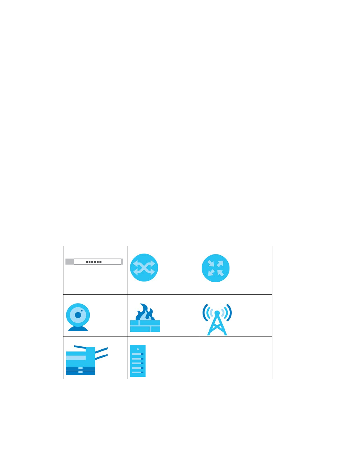
Icons Used in Figures
Figures in this user guide may use the following generic icons. The Switch icon is not an exact
representation of your device.
Switch Generic Switch Generic Router
IP Camera Firewall Cell Tower
Printer Server
GS1200 Series User’s Guide
3

Contents Overview
Contents Overview
User’s Guide ........................................................................................................................................8
Getting to Know Your Switch ................................................................................................................ 9
Hardware Installation ........................................................................................................................... 13
Hardware Panels .................................................................................................................................. 16
Web Configurator ................................................................................................................................. 19
Initial Setup Example ............................................................................................................................ 24
Tutorials .................................................................................................................................................. 27
Technical Reference ........................................................................................................................39
System .................................................................................................................................................... 40
Port ......................................................................................................................................................... 44
VLAN ...................................................................................................................................................... 50
Link Aggregation .................................................................................................................................. 53
Mirroring ................................................................................................................................................. 55
QoS ......................................................................................................................................................... 57
IGMP Snooping ..................................................................................................................................... 61
Management ........................................................................................................................................ 63
Troubleshooting .................................................................................................................................... 67
GS1200 Series User’s Guide
4

Table of Contents
Table of Contents
Document Conventions .................................................................. ....................................................3
Contents Overview..............................................................................................................................4
Table of Contents.................................................................................................................................5
Part I: User’s Guide............................................................................................ 8
Chapter 1
Getting to Know Your Switch ..............................................................................................................9
1.1 Introduction ....................................................................................................................................... 9
1.2 Applications .................................................................................................................................... 10
1.2.1 Bridging Application ............................................................................................................. 10
1.2.2 VLAN Application Example .................................................................................................. 11
1.3 Ways to Manage the Switch ......................................................................................................... 11
1.4 Good Habits for Managing the Switch ........................................................................................11
Chapter 2
Hardware Installation ........................................................................................................................13
2.1 Installation Scenarios ...................................................................................................................... 13
2.2 Safety Precautions .......................................................................................................................... 13
2.2.1 Freestanding Installation Procedure ................................................................................... 13
2.2.2 Wall Mounting ....................................................................................................................... 14
Chapter 3
Hardware Panels................................................................................................................................16
3.1 Front Panel ...................................................................................................................................... 16
3.2 Rear Panel ....................................................................................................................................... 16
3.2.1 Power Connector ................................................................................................................. 17
3.3 LEDs .................................................................................................................................................. 18
Chapter 4
Web Configurator...............................................................................................................................19
4.1 Overview ......................................................................................................................................... 19
4.2 System Login .................................................................................................................................... 19
4.3 Web Configurator Layout .............................................................................................................. 20
4.3.1 Change Your Password ........................................................................................................ 22
4.4 Switch Lockout / Resetting the Switch ......................................................................................... 22
GS1200 Series User’s Guide
5

Table of Contents
4.5 Logging Out of the Web Configurator ........................................................................................23
Chapter 5
Initial Setup Example.........................................................................................................................24
5.1 Overview ......................................................................................................................................... 24
5.1.1 Change the IP Address ........................................................................................................ 24
5.1.2 Change the Password .......................................................................................................... 25
Chapter 6
Tutorials...............................................................................................................................................27
6.1 Overview ......................................................................................................................................... 27
6.2 Creating a VLAN and Setting Port VID ......................................................................................... 27
6.2.1 Setting Port VID ...................................................................................................................... 29
6.3 Setting Up Bandwidth Control ...................................................................................................... 30
6.4 Setting Up QoS (Quality of Service) .............................................................................................. 32
6.5 Upgrade Firmware on the Switch ................................................................................................. 34
6.6 Back up a Configuration File ......................................................................................................... 35
6.7 Restore Configuration .................................................................................................................... 36
6.8 Power over Ethernet (PoE) Configuration ....................................................................................37
Part II: Technical Reference...........................................................................39
Chapter 7
System.................................................................................................................................................40
7.1 Overview ......................................................................................................................................... 40
7.2 System Screen ................................................................................................................................. 40
Chapter 8
Port ......................................................................................................................................................44
8.1 Overview ......................................................................................................................................... 44
8.1.1 What You Need to Know ..................................................................................................... 44
8.2 Port Settings ..................................................................................................................................... 46
8.2.1 Advanced Settings ............................................................................................................... 47
Chapter 9
VLAN....................................................................................................................................................50
9.1 Overview ......................................................................................................................................... 50
9.1.1 IEEE 802.1Q Tagged VLANs .................................................................................................. 50
9.2 VLAN Settings .................................................................................................................................. 51
Chapter 10
Link Aggregation .................................... .... .... ... ............................................ .... .... ............................53
GS1200 Series User’s Guide
6

Table of Contents
10.1 Overview ....................................................................................................................................... 53
10.2 Link Aggregation .......................................................................................................................... 53
Chapter 11
Mirroring..............................................................................................................................................55
11.1 Overview ....................................................................................................................................... 55
11.2 Mirroring Settings ........................................................................................................................... 55
Chapter 12
QoS......................................................................................................................................................57
12.1 Overview ....................................................................................................................................... 57
12.2 What You Need to Know ............................................................................................................. 57
12.2.1 Port-Based QoS ................................................................................................................... 58
12.2.2 IEEE 802.1p QoS ................................................................................................................... 58
12.3 Port-Based QoS Screen ................................................................................................................ 59
12.4 IEEE 802.1P QoS Screen ................................................................................................................ 59
Chapter 13
IGMP Snooping ..................................................................................................................................61
13.1 Overview ....................................................................................................................................... 61
13.2 IGMP Snooping Settings ............................................................................................................... 61
Chapter 14
Management .....................................................................................................................................63
14.1 Overview ....................................................................................................................................... 63
14.1.1 What You Need to Know ...................................................................................................63
14.2 Management Settings ................................................................................................................. 63
14.2.1 Firmware Upgrade .............................................................................................................. 65
Chapter 15
Troubleshooting..................................................................................................................................67
15.1 Power, Hardware Connections, and LEDs ................................................................................. 67
15.2 Switch Access and Login ............................................................................................................. 68
15.3 Switch Configuration .................................................................................................................... 70
Appendix A Customer Support ....................................................................................................... 71
Appendix B Legal Information......................................................................................................... 77
Index...................................................................................................................................................81
GS1200 Series User’s Guide
7

PART I
User’s Guide
8

CHAPTER 1
Getting to Know Your Switch
1.1 Introduction
This chapter introduces the main features and applications of the Switch. The GS1200 Series consists of
the following models:
• GS1200-5
• GS1200-5HP v2
• GS1200-8
• GS1200-8HP v2
You can easily connect different devices, such as computers, network storage devices, IP cameras,
print servers to your home network.
The PoE ports of the GS1200-5HP v2 and GS1200-8HP v2 support IEEE 802.3at High Power over Ethernet
(PoE) and IEEE 802.3af PoE standard, to provide power to IP camera, wall mounted access point, and
other devices that may be far from a power outlet. These devices receive power from the Switch
through an Ethernet port. Aside from minimizing the need for cables and wires, PoE removes the hassle
of trying to find a nearby electric outlet to power up devices.
The Switch also provides a utility like Web Configurator to give you an easy configuration for VLAN, QoS,
basic system management, and firmware upgrade. The Switch is compliant with IEEE 802.3az (Energy
Efficient Ethernet Standard), and provides power-saving benefits without compromising performance.
VLANs allow you to limit access to a specified group of users by dividing workstations into different
isolated LAN segments.
Quality of Service (QoS) refers to both a network's ability to deliver data with minimum delay, and the
networking methods used to control the use of bandwidth. Without QoS, all traffic data is equally likely
to be dropped when the network is congested.
Bandwidth control allows you to set the maximum bandwidth allowed in kilobits per second (kbps) for
incoming and out-going traffic flow on a port.
Key feature differences between Switch models are as follows. Other features are common to all
models.
Table 1 GS1200 Series Comparison Table
MODEL GS1200-5 GS1200-5HP V2 GS1200-8 GS1200-8HP V2
Total Port Number 5 5 8 8
10/100/1000 Mbps PoE Ports – Ports 1 – 4 – Ports 1 – 4
10/100/1000 Mbps Ethernet Ports Ports 1 – 5 Port 5 Ports 1 – 8 Ports 5 – 8
GS1200 Series User’s Guide
9

Chapter 1 Getting to Know Your Switch
Table 1 GS1200 Series Comparison Table (continued)
MODEL GS1200-5 GS1200-5HP V2 GS1200-8 GS1200-8HP V2
PoE Feature – IEEE 802.3 af PoE
– IEEE 802.3 af PoE
PoE Maximum Power – 60 W PoE power
Power ON/OFF Switch – v – v
802.1p QoS and Port-Based QoS v v v v
IGMP Snooping v1/v2 and v3
Compatible
Broadcast Storm Control v v v v
Port Isolation v v v v
Bandwidth Control – – v v
Management VLAN v v v v
Firmware Upgrade v v v v
Configuration Restore and
Backup
Bandwidth control allows you to set the maximum bandwidth allowed on a port.
1.2 Applications
IEEE 802.3at High
Power over
Ethernet (PoE)
– 60 W PoE power
budget
vvvv
vvvv
IEEE 802.3at High
Power over
Ethernet (PoE)
budget
This section shows a few examples of using the Switch in various network environments.
1.2.1 Bridging Application
In this example the Switch connects different company departments (RD and Sales) to the corporate
backbone. It can alleviate bandwidth contention and eliminate server and network bottlenecks. All
users that need high bandwidth can connect to high-speed department servers via the Switch.
Figure 1 Bridging Application
GS1200 Series User’s Guide
10
Chapter 1 Getting to Know Your Switch
1.2.2 VLAN Application Example
A VLAN (Virtual Local Area Network) allows a physical network to be partitioned into multiple logical
networks. Stations on a logical network belong to one or more groups. With VLAN, a station cannot
directly talk to or hear from stations that are not in the same group(s) unless such traffic first goes through
a router.
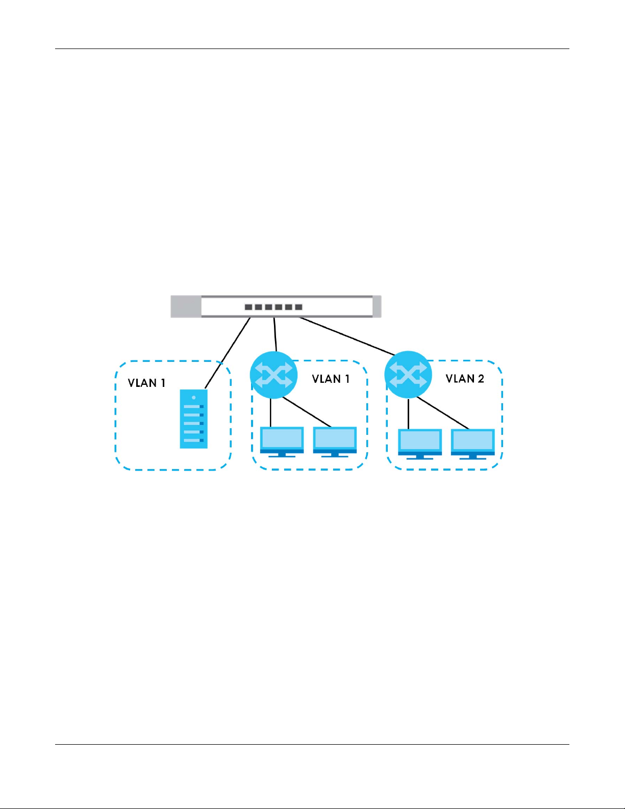
1.2.2.1 Tag-based VLAN Example
Ports in the same VLAN group share the same frame broadcast domain, thus increasing network
performance by reducing broadcast traffic. VLAN groups can be modified at any time by adding,
moving or changing ports without any re-cabling.
Shared resources such as a server can be used by all ports in the same VLAN as the server. In the
following figure only ports that need access to the server need to be part of VLAN1. Ports can belong to
other VLAN groups too.
Figure 2 Shared Server Using VLAN Example
1.3 Ways to Manage the Switch
Use the Web Configurator to manage the Switch. This allows easy Switch setup and management using
a (supported) web browser. See Chapter 4 on page 19.
1.4 Good Habits for Managing the Switch
Do the following things regularly to make the Switch more secure and to manage the Switch more
effectively.
• Change the password. Use a password that is not easy to guess and that consists of different types of
characters, such as numbers and letters.
• Write down the password and put it in a safe place.
GS1200 Series User’s Guide
11

Chapter 1 Getting to Know Your Switch
• Back up the configuration (and make sure you know how to restore it). Restoring an earlier working
configuration may be useful if the device becomes unstable or even crashes. If you forget your
password, you will have to reset the Switch to its factory default settings. If you backed up an earlier
configuration file, you would not have to totally re-configure the Switch. You could simply restore your
last configuration.
GS1200 Series User’s Guide
12

Hardware Installation
2.1 Installation Scenarios
This chapter shows you how to install and connect the Switch.
2.2 Safety Precautions
Please observe the following before using the Switch:
• Do NOT stack Switches with fans.
• It is recommended to ask an authorized technician to attach the Switch on a desk or to the rack or
wall. Use the proper screws to prevent damage to the Switch. See the Screw Specifications figure in
this chapter to know the type of screw and screw driver for this model.
• Make sure there is at least 2 cm of clearance on the top and bottom of the Switch, and at least 5 cm
of clearance on all four sides of the Switch. This allows air circulation for cooling.
• Do NOT block the ventilation holes nor store cables or power cords on the Switch. Allow clearance for
the ventilation holes to prevent your Switch from overheating. This is especially crucial when your
Switch does not have fans. Overheating could affect the performance of your Switch, or even
damage it.
• The surface of the Switch could be hot when it is functioning. Do NOT put your hands on it. You may
get burned. This could happen especially when you are using a fanless Switch.
• The Switches with fans are not suitable for use in locations where children are likely to be present.
CHAPTER 2
To start using the Switch, simply connect the power cable and turn it on.
2.2.1 Freestanding Installation Procedure
1 Make sure the Switch is clean and dry.
2 Attach the rubber feet as shown if they are not already attached – see Figure 3 on page 14.
3 Set the Switch on a smooth, level surface strong enough to support the weight of the Switch and the
connected cables. Make sure there is a power outlet nearby.
4 Make sure there is enough space around the Switch to allow the attachment of cables and the power
cord and allow sufficient air circulation.
Note: Make sure you are using the correct type of Ethernet cable (Category 5e, 6UTP/STP, or
better Ethernet cable).
GS1200 Series User’s Guide
13

Figure 3 Attach Rubber Feet
2.2.2 Wall Mounting
The distance between mounting holes for each Switch is as follows.
Table 2 Wall Mounting Distances
MODEL DISTANCE ‘D’ BETWEEN MOUNTING HOLES
GS1200-5 91 mm / 3.58 in
GS1200-8 75mm / 2.95 in
GS1200-5HP V2 65mm / 2.55 in
GS1200-8HP v2 180 mm / 7.09 in
Do the following to mount your Switch on a wall.
1 Drill two holes a distance ‘D’ apart into a wall – see Figure 4 on page 15.
2 Place two screw anchors in the holes. Screw two screws into the screw anchors. Do not screw the screws
all the way in to the wall; leave a small gap between the head of the screw and the wall.
3 The gap must be big enough for the screw heads to slide into the screw slots and the power cord to run
down the back of the Switch.
Note: Make sure the screws are securely fixed to the wall and strong enough to hold the
weight of the Switch with the connection cables.
4 Use the mounting holes on the Switch to hang the Switch on the screws.
Wall mount the Switch with the Ethernet ports facing down and the
ventilation holes on the side.
GS1200 Series User’s Guide
14
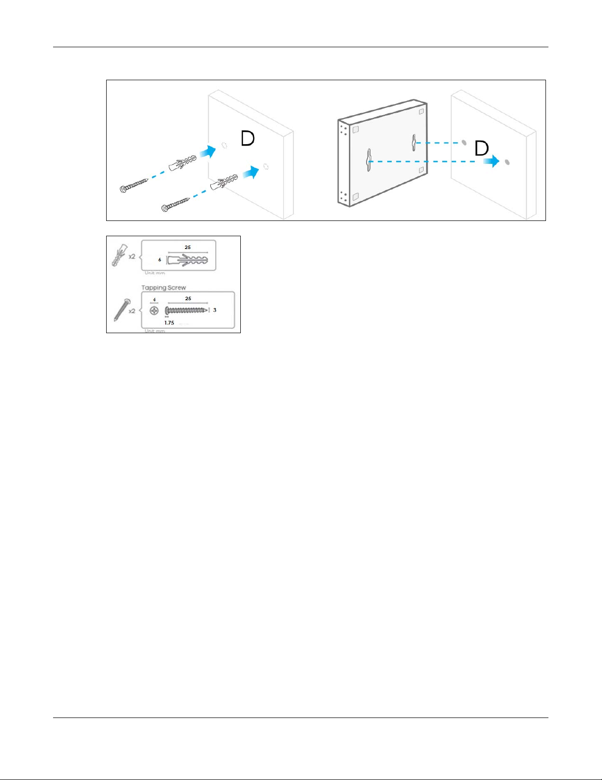
Figure 4 Wall Mounting
Figure 5 Screw Specifications
Chapter 2 Hardware Installation
GS1200 Series User’s Guide
15
This chapter describes the front panel and rear panel of the Switch and shows you how to make the
hardware connections.
3.1 Front Panel
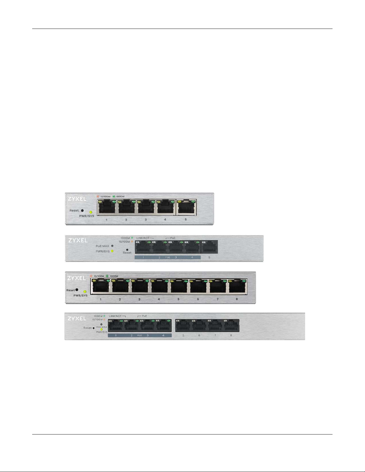
The following figures show the front panels of the Switch.
Figure 6 Front Panel: GS1200-5
Chapter 3 Hardware Panels
CHAPTER 3
Hardware Panels
Figure 7 Front Panel: GS1200-5HP v2
Figure 8 Front Panel: GS1200-8
Figure 9 Front Panel: GS1200-8HP v2
3.2 Rear Panel
The following figures show the rear panels of the Switch.
GS1200 Series User’s Guide
16

Chapter 3 Hardware Panels
Figure 10 Rear Panel: GS1200-5
Figure 11 Rear Panel: GS1200-5HP v2
Figure 12 Rear Panel: GS1200-8
Figure 13 Rear Panel: GS1200-8HP v2
3.2.1 Power Connector
Note: Make sure you are using the correct power source as shown on the panel.
To connect power to the Switch, insert the female end of the power cord to the AC power receptacle
on the rear panel. Connect the other end of the supplied power cord to a power outlet. Make sure that
no objects obstruct the airflow.
GS1200 Series User’s Guide
17

3.3 LEDs
After you connect the power to the Switch, view the LEDs to ensure proper functioning of the Switch
and as an aid in troubleshooting.
Table 3 LED Descriptions
LED COLOR STATUS DESCRIPTION
PWR/SYS Green On The system power is on.
LINK/ACT Amber (10/100
PoE
(GS1200-5HP
v2 & GS12008HP v2)
PoE MAX
(GS1200-5HP
v2 & GS12008HP v2)
Chapter 3 Hardware Panels
Blinking The system is starting up.
Off The system power is off.
Mbps)
Green (1000
Mbps)
Green On PoE is enabled and power is supplied to the connected PoE-
Amber On More than 50 W has been supplied to the PoE-enabled devices,
On The port has a successful 10/100 Mbps or 1000 Mbps connection.
Blinking The system is transmitting data through the port.
Blinking
once a
second
Off The port is disconnected or disabled.
Off PoE is disabled or power is not being supplied.
Off Less than 50 W has been supplied to the PoE-enabled devices.
If you enable Loop Detection in the Port screen, the port in a loop
state will blink fast.
If you enable Loop Prevention in the Port screen, all ports will blink
fast. Later, the port in a loop state will be off. If a loop happens
on two ports, all ports will blink fast. Later, the higher-numbered
port will be off.
If you enable Loop Prevention in the Port screen, and a loop
happens on two ports, the higher-numbered port will be off.
enabled device.
and the PoE power output is approaching the power budget.
GS1200 Series User’s Guide
18
4.1 Overview
This section introduces the configuration and functions of the Web Configurator.
The Web Configurator is an HTML-based management interface that allows easy system setup and
management via Internet browser. Use a browser that supports HTML5, such as Microsoft Edge, Internet
Explorer 11, Mozilla Firefox, or Google Chrome. The recommended screen resolution is 1024 by 768 pixels.
In order to use the Web Configurator you need to allow:
• Web browser pop-up windows from your device.
• JavaScript (enabled by default).
• Java permissions (enabled by default).
CHAPTER 4
Web Configurator
4.2 System Login
1 Start your web browser.
2 Type “http://” and the IP address of the Switch (for example, the default management IP address is
192.168.1.3) in the Location or Address field. Press [ENTER]. Your computer must be in the same subnet in
order to access this website address.
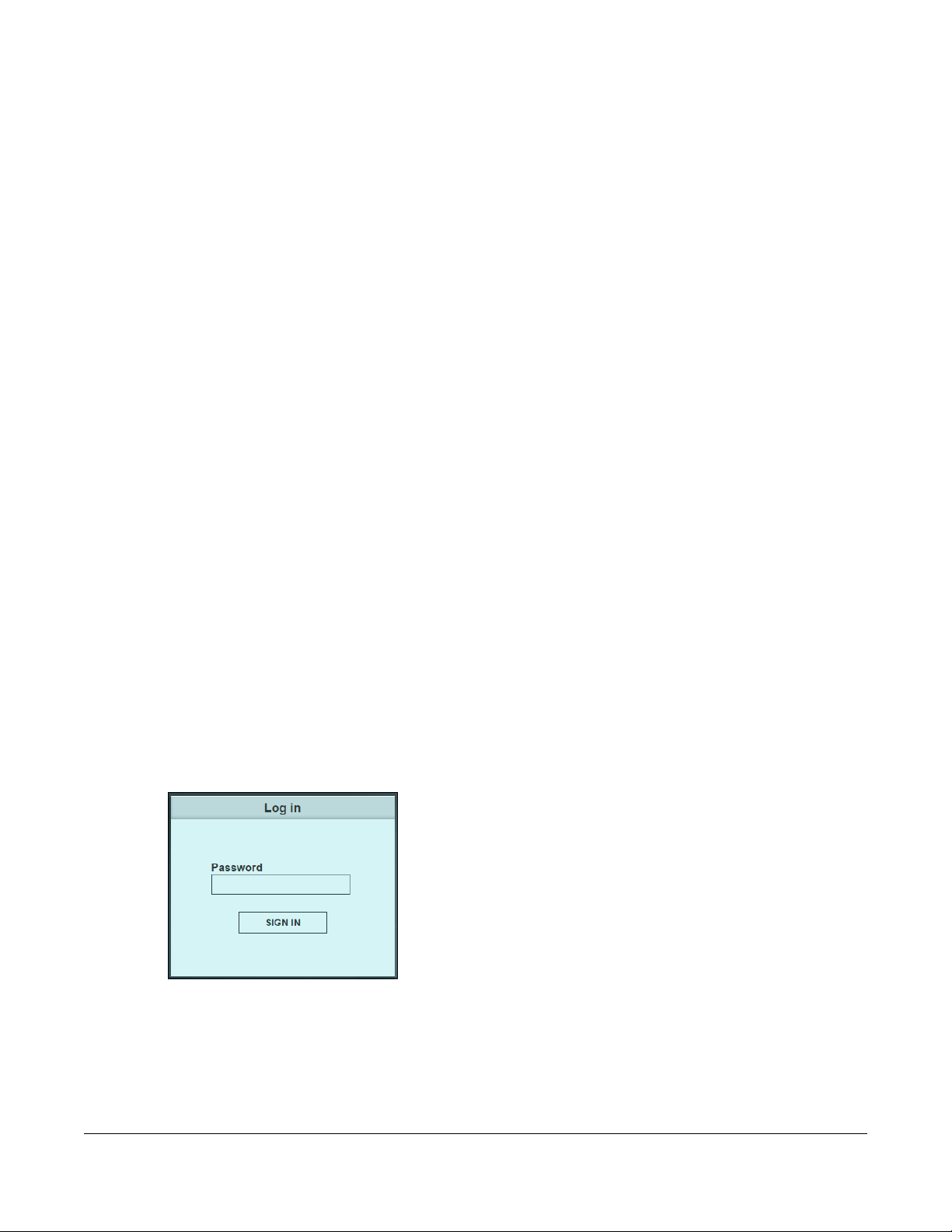
3 The login screen appears. The default password is 1234.
Figure 14 Web Configurator: Login
4 The following screen displays if you log into the Switch for the first time. Enter a new password using the
keyboard characters ("a – z", "A – Z", "0 – 9"). The password must be 8 to 15 characters long. Retype it to
confirm and click Apply to view the first Web Configurator screen.
For GS1200-5HP and GS1200-8HP, you can enter the default password 1234 again, if you do not want to
change your password.
GS1200 Series User’s Guide
19

Chapter 4 Web Configurator
Figure 15 Web Configurator: Login
4.3 Web Configurator Layout
The System screen is the first screen that displays when you access the Web Configurator.
This guide uses the GS1200-8 and GS1200-5HP v2 screens as examples. The screens may vary slightly for
different models.
The following figure shows the navigating components of a Web Configurator screen.
GS1200 Series User’s Guide
20
Chapter 4 Web Configurator
A
B
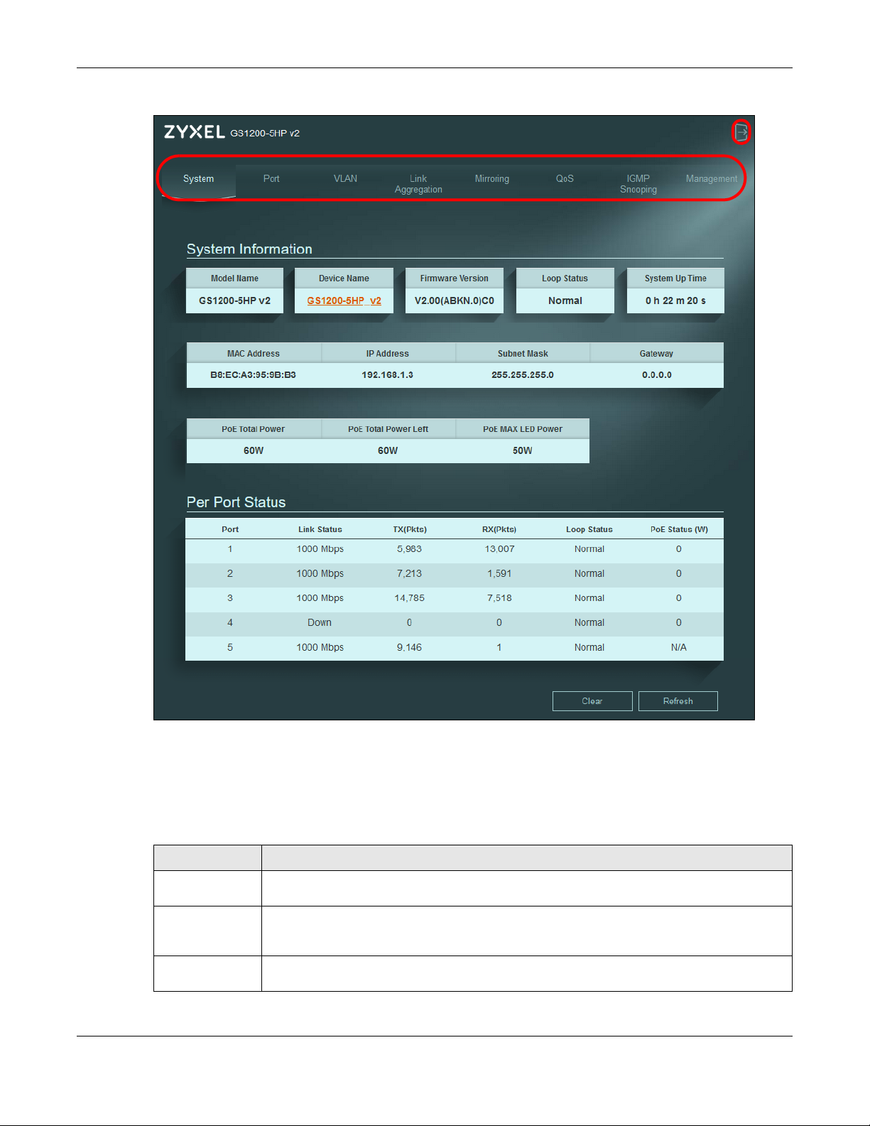
Figure 16 Web Configurator Layout
A - Click the menu items to open the screen in the main window.
B - Click this link to log out of the Web Configurator.
The following table describes the links in the navigation panel.
Table 4 Navigation Panel Links
LINK DESCRIPTION
System This link takes you to a screen that displays general system information, PoE status, and
individual port statistics.
Port This link takes you to a screen to enable Broadcast Storm Control and Loop Prevention/Loop
Detection. You can also configure the transmission speed, flow control, port isolation,
bandwidth control, and PoE on a port.
VLAN This link takes you to a screen where you can set the PVID (Port VLAN ID) on a port and create/
modify/delete IEEE 802.1Q VLAN for the Switch.
GS1200 Series User’s Guide
21
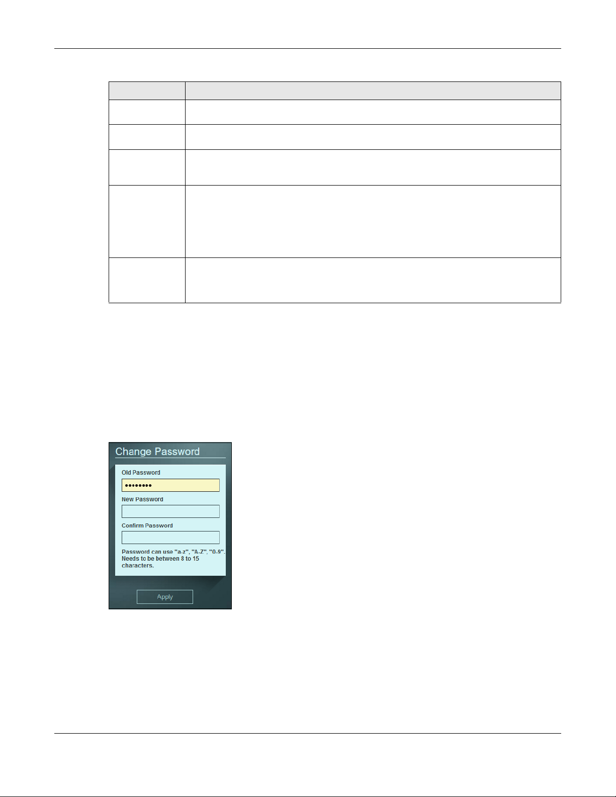
Table 4 Navigation Panel Links (continued)
LINK DESCRIPTION
Link Aggregation This link takes you to screens where you can logically aggregate physical links to form one
logical and higher-bandwidth link.
Mirroring This link takes you to a screen where you can copy traffic from one port or ports to another port
so that you can examine the traffic from the first port without interference.
QoS This link takes you to a screen where you can configure port-based or IEEE 802.1p QoS. The
Switch can put packets into the queues according to the port on which the packet is received
or the priority tag in the packet.
IGMP Snooping This link takes you to a screen where you can configure IGMP snooping. You must enable IGMP
snooping to use the IPTV service. It checks the IGMP packets passing through it, picks out the
group registration information, and configures multicasting accordingly.
Traditionally, packets are transmitted in one of either two ways – Unicast (one sender to one
recipient) or Broadcast (one sender to everybody on the network). Multicast delivers packets
to just a group of hosts on the network.
Management This link takes you to screens where you can change the system login password, perform
firmware upgrade and configuration file maintenance as well as reset/reboot the system. You
can also configure the IP address and subnet mask, set management VID, and enable IEEE
802.3az EEE.
4.3.1 Change Your Password
Chapter 4 Web Configurator
After you log in for the first time, you must enter a new password using the keyboard characters ("a – z",
"A – Z", "0 – 9"). The password must be 8 to 15 characters long. Click Management to display the next
screen to change your login password.
For GS1200-5HP and GS1200-8HP, you can enter the default password 1234 again, if you do not want to
change your password.
Figure 17 Change Administrator Login Password
4.4 Switch Lockout / Resetting the Switch
You could block yourself (and all others) from managing the Switch if you do one of the following:
1 Remove all ports from VLAN1 and you do not configure other VLAN groups.
GS1200 Series User’s Guide
22

Chapter 4 Web Configurator
2 Forget the password and/or IP address.
3 You forgot to log out of the Switch from a computer before logging in again on another computer.
Note: Be careful not to lock yourself and others out of the Switch.
If you forget the administrator password or cannot access the Web Configurator, you will need to use
the Reset button at the front panel of the
This means that you will lose all configurations that you had previously and the password will be reset to
“1234”. IP address will also be reset to 192.168.1.3.
1 Make sure the PWR/SYS LED is on (not blinking).
2 To set the device back to the factory default settings, press the Reset button for 10 seconds or until the
PWR/SYS LED begins to blink and then release it. When the PWR/SYS LED begins to blink, the defaults
have been restored and the device restarts.
Switch to reset it back to the factory defaults.
4.5 Logging Out of the Web Configurator
Click the logout icon in a screen to exit the Web Configurator. You have to log in with your password
again after you log out. This is recommended after you finish a management session for security reasons.
Note: You are automatically logged out of the Web Configurator after 5 minutes of inactivity.
GS1200 Series User’s Guide
23
Initial Setup Example
5.1 Overview
This chapter shows how to set up the Switch for use.
The following lists the configuration steps for the initial setup:
• Change the IP Address
• Change the Password
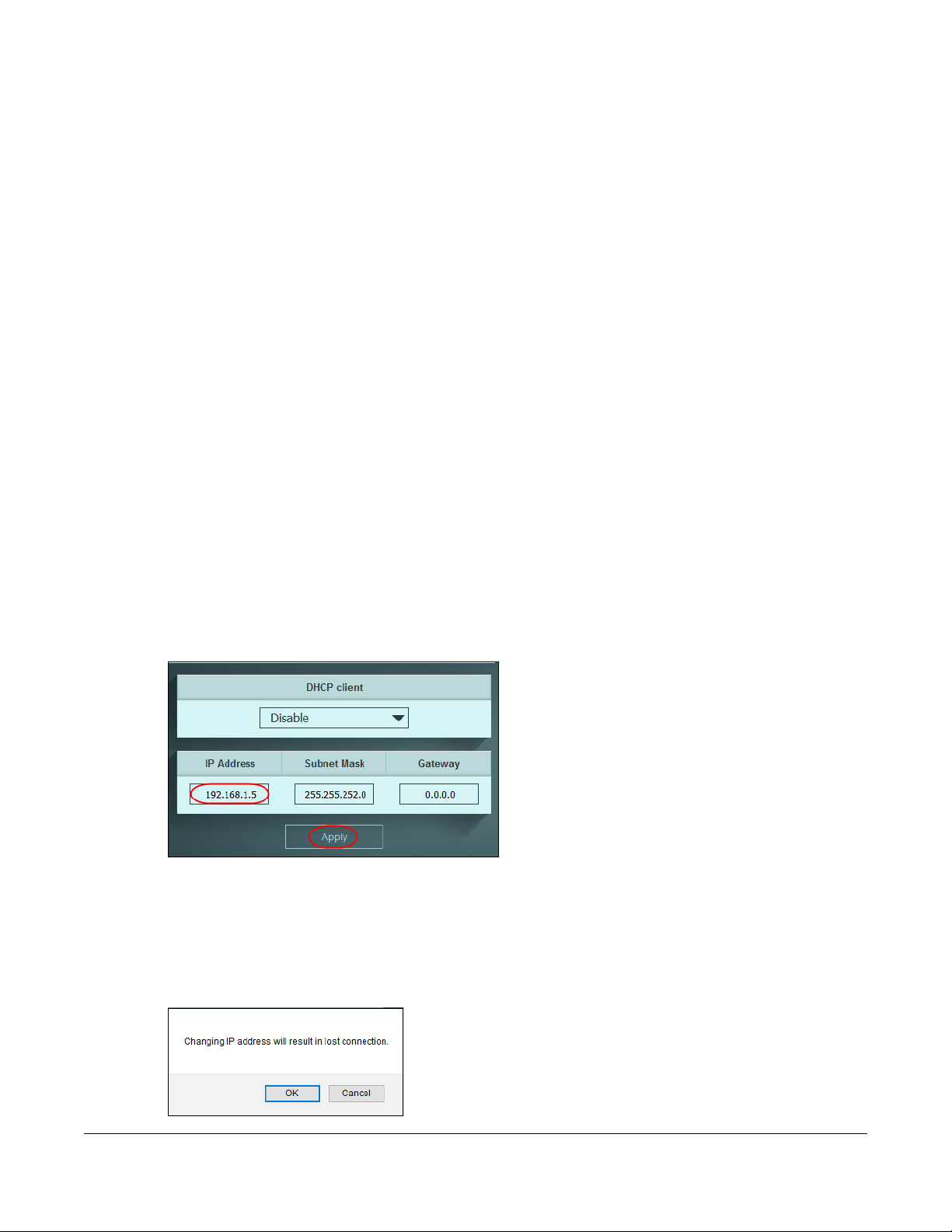
5.1.1 Change the IP Address
If you do not wish to set your Switch as a DHCP client (DHCP client field is Disable), assign an IP address
for the Switch. The IP address makes it accessible from an outside network. It is used by the Switch to
communicate with other devices in other networks.
CHAPTER 5
In this example, you want to change the IP address to 192.168.1.5.
1 Click Management in the navigation panel to open the following screen.
Figure 18 Change the IP Address
2 Enter the new IP address 192.168.1.5 in the IP Address field.
3 Click Apply.
4 The following screen appears. Click OK to save the setting. Connection to the Web Configurator will be
lost.
Figure 19 Lost Connection Warning
GS1200 Series User’s Guide
24
5 On your web browser, go to http://192.168.1.5.
6 A Log in screen appears. Enter the existing password and click SIGN IN to log in via the new IP address.
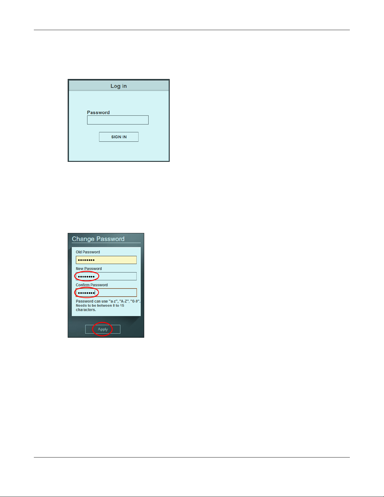
5.1.2 Change the Password
The first time you log in to the Web Configurator, you will be asked to change the default password
1234. If you wish to change the password again, perform the following steps:
Chapter 5 Initial Setup Example
1 Click Management in the navigation panel to open the following screen.
Figure 20 Change the Password
2 Enter the existing password in the Old Password field.
3 Enter the new system password in the New Password field using the keyboard characters (a – z, A – Z, 0 –
9). The password must be 8 to 15 characters long.
4 Enter the new password again to in the Confirm Password field for confirmation.
5 Click Apply. You will automatically be logged out of the Web Configurator.
6 A Log in screen appears. Enter the new password and click SIGN IN to log in using the new password.
GS1200 Series User’s Guide
25

Chapter 5 Initial Setup Example
GS1200 Series User’s Guide
26
 Loading...