

ZyXEL GS1100-8HP, GS1100-16, GS1100-24E, GS1100-10HP, GS1100-24 User Manual

GS1100 Series
Unmanaged Gigabit Etherne t Switch
Version 1.00
Edition 5, 09/2015
Quick Start Guide
User’s Guide
www.zyxel.com
Copyright © 20 15 ZyXEL Communications Corporation

IMPORTANT!
READ CAREFULLY BEFORE USE.
KEEP THIS GUIDE FOR FUTURE REFERENCE.
Scre enshots and graphics in this book may differ slightly from your produc t due to differe nces in
your product firmware or your computer operating system. Every effort has been made to ensure
that the information in this manual is accurate.
• More Information
Go to support.zyxel. com to find other information on the Switch.
GS1100 Series User’s Guide
2

Table of Contents
Table of Contents
Table of Contents .................................................................................................................................3
Chapter 1
Getting to Know Your Switch...............................................................................................................4
1.1 Introduction .........................................................................................................................................4
1.2 Features ..............................................................................................................................................5
1.3 Applications .........................................................................................................................................6
1.3.1 Standalone Workgroup ..............................................................................................................6
1.3.2 Bridging .....................................................................................................................................6
1.4 Power Over Ethernet (PoE) ................................................................................................................7
Chapter 2
Hardware Description and Connection ..............................................................................................8
2.1 Rear Panel ....................................................................................................................................... 8
2.1.1 Rear Panel Power Connection ..................................................................................................8
2.2 Front Panel ..........................................................................................................................................9
2.2.1 RJ-45 Auto-negotiating Ports ....................................................................................................9
2.2.2 IEEE 802.3az EEE ....................................................................................................................9
2.2.3 SFP Slots (GS1100-24 and GS1100-10HP) ..............................................................................9
2.2.4 Front Panel Connections ......................................................................................................... 11
2.2.5 Front Panel LEDs .................................................................................................................... 11
2.3 Hardware Installation ........................................................................................................................14
2.3.1 Wall Mounting ..........................................................................................................................14
2.3.2 Rack Mounting ......................................................................................................................... 15
2.3.3 Mounting the Switch on a Rack ...............................................................................................16
Chapter 3
Troubleshooting..................................................................................................................................18
3.1 Improper Network Cabling and Topology ..........................................................................................19
Appendix A Legal Information............................................................................................................20
Index ....................................................................................................................................................29
GS1100 Series User’s Guide
3

CHAPTER 1
Getting to Know Your Switch
1.1 Introduction
This chapter describes the key fea tures, benefits and applicati ons of your Switch.
This User’s Guide covers the following models: GS1100-8HP, GS1100-16, GS1100-24, GS1100-24E
and GS1100-10HP. The Switch is a 10/ 100/ 1000 Mbps multi-port switch that can be used to build
high-performance switched wor kgroup networks. The Switch is a store-and-forward device that
offers low latency for high-speed networking. The Switch is fanl ess and designed for workgroups,
departments or backb one computing envir onments fo r small businesses.
Table 1 GS1100 Series Comparison Table
PORT/SWITCH DETAILS GS1100-8HP GS1100-16 GS1100-24 GS1100-24E GS1100-10HP
10/ 100/ 1000Base-T Ethernet ports
100/1000Base-X SFP slots 22
802.3AT PoE ports 4 8
One physical IEEE 802.3az ON/OFF button 11111
One power ON/OFF switch 1 1 1 1
8 162424 8
The GS1100-8HP has four GbE PoE ports that can supply power to the connected PoE powered
devices.
The GS1100-10HP has eight GbE PoE ports that can supply power to the connected PoE powered
devices.
The GS1100-24 and GS1100-10HP have two SFP slots for uplink connection. Use SFP transceivers
in these slots for 100Mbps or 1Gbps connections to backbone Ethernet switches.
The Switch has a built-in algorithm that automatically assigns priority to received packets. It can
operate in low power idle mode in compliance with IEEE 802.3az Energy Efficient Ethernet (EEE).
GS1100 Series User’s Guide
4
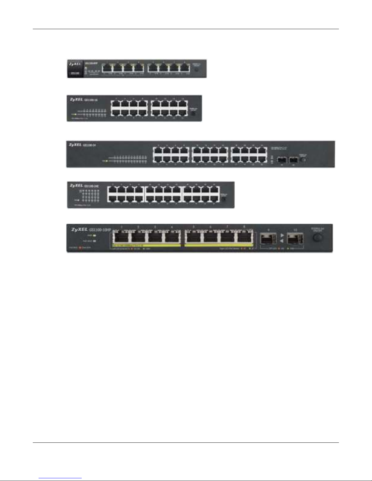
Figure 1 Front Panel
GS1100-8HP
GS1100-16
GS1100-24
GS1100-24E
GS1100-10HP
Chapter 1 Getting to Know Your Switch
1.2 Features
The following are the essential features of the Switch.
• Conforms to I EEE 802.3, 802.3u, 802.3ab and 802.3x standards.
• Auto-negotiating 10/ 100/ 1000 Mbps Gigabit Ethernet (GbE) RJ-45 ports.
• Auto-sensing crossover for all 10/100/1000 Mb ps Gigabit Ethernet (GbE) RJ- 45 ports.
• Supports N-Way protocol for speed (10/100/ 1000 Mbps) and duplex mode (Half/Full) autodetection.
• Supports store-and-forward switching.
• Supports automatic address learning.
• Supports IEEE 802.3az EEE
• Supports IEEE 802.3af and IEEE 802.3at PoE standards (GS1100-8HP and GS1100-10HP)
• Full wire speed forwarding rate.
• Supports 802.1p CoS.
• Embedded 8K MAC address tabl e providing 8000 MAC addres ses entries.
GS1100 Series User’s Guide
5
Chapter 1 Getting to Know Your Switch
1.3 Applications
This section provides two network topology examples in which the Switch is used.
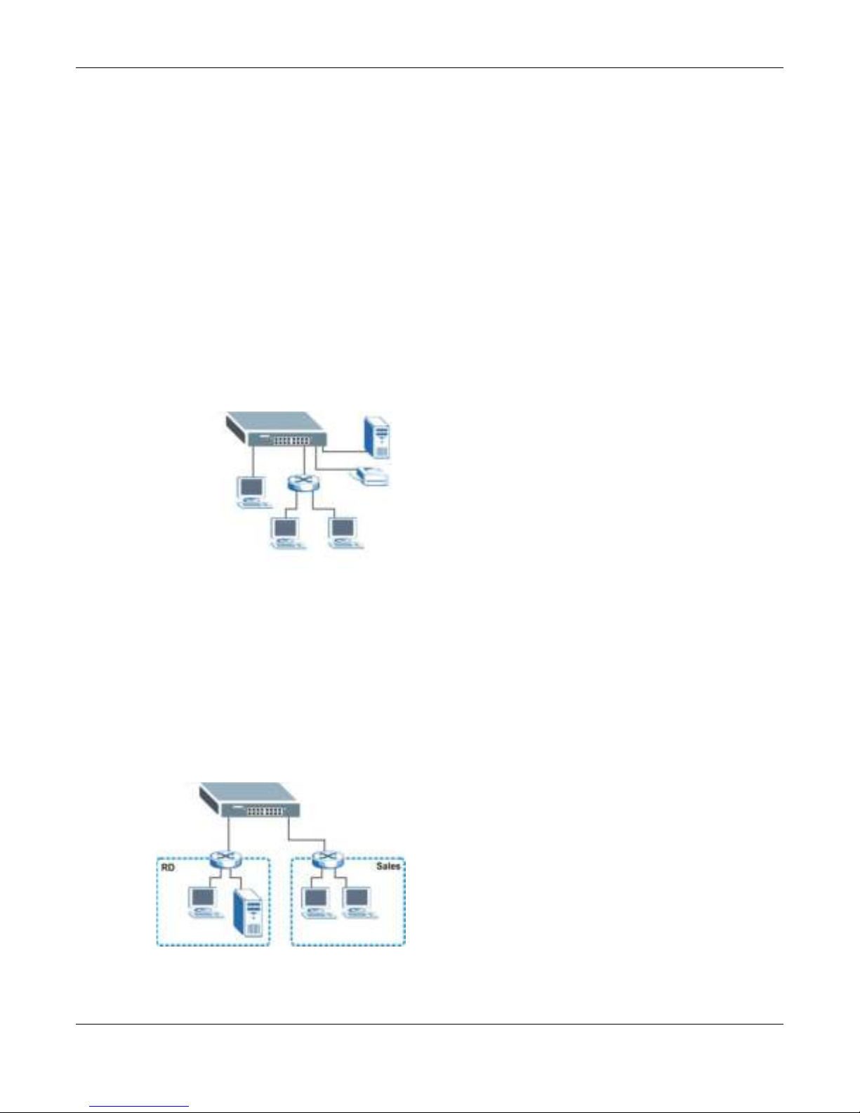
1.3.1 Standalone Workgroup
In this application, the Switch is an ideal solution for small networks where rapid growth can be
expected in the near future.
The Switch can be used standalone for a gr oup of heavy traffic users. You can connect computers
directly to the Switch’s port or connect other switches to the Switch.
In this example, all computers can shar e hig h-speed applications on the serv er. To expand the
network, si m ply add more networking devices such as switches, routers, computers , print servers
etc.
Figure 2 Standalone Workgroup Example
1.3.2 Bridging
With its large address table and high performance, the Switch is a n ideal solution for department
networks to connect to the corporate backbone or for connecting network segments.
The following figure depicts a typi cal segment bridge application of the Switch in an enterprise
environment. The two networks (R&D and Sales), the standalone server and the computers can all
com municate with each other a nd share all network resources.
Figure 3 Bridging Example
GS1100 Series User’s Guide
6
Chapter 1 Getting to Know Your Switch
1.4 Power Over Ethernet (PoE)
The PoE function is available for GS1100-8HP and GS1100-10HP.
Ports 1 to 4 on the GS1100-8HP are IEEE 802.3at High Power over Ethernet (PoE) compliant and
can supply power of up to 30W per Ethernet port and up to the total PoE power budget per Switch.
Ports 1 to 8 on the GS1100-10HP support both the IEEE 802.3af Power over Ethernet and IEEE
802.3at High Power over Ethernet standards. The ports supply power of up to 30W per Ethernet
port and up to the total PoE power budget per Switch.
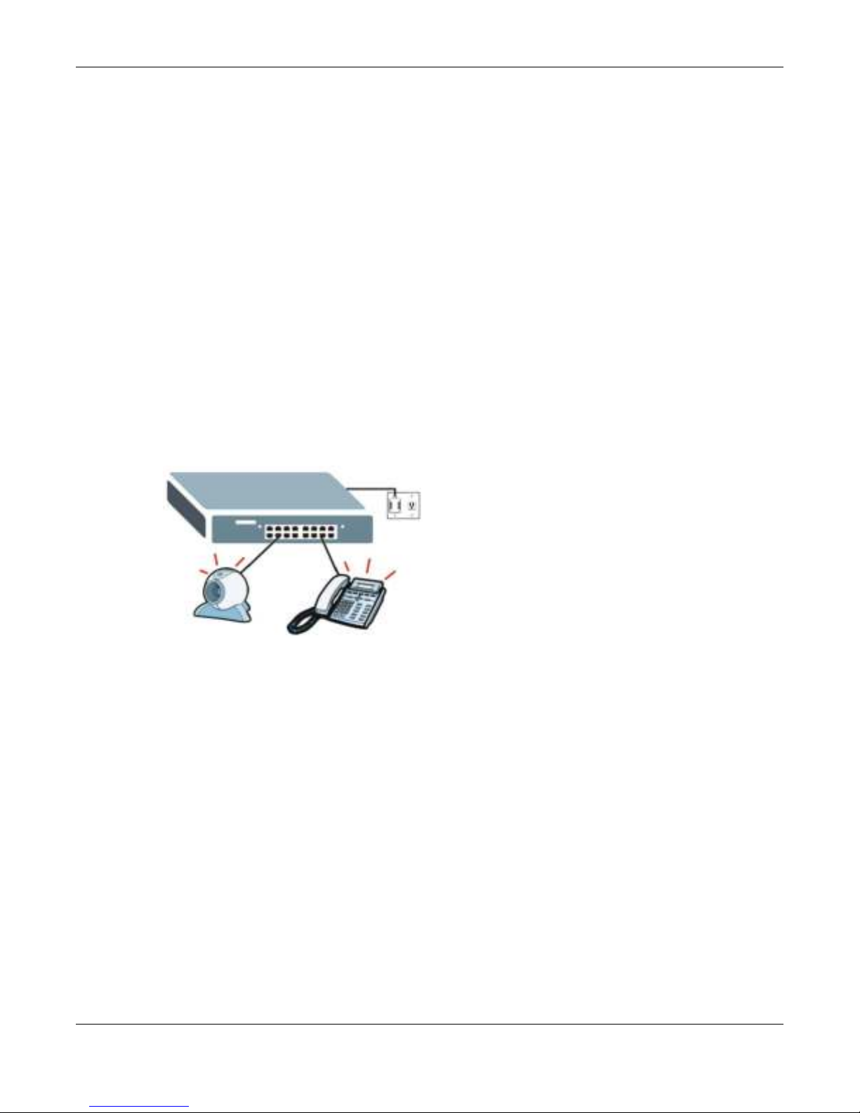
The Switch is Power Sourc ing Equipment (PSE) because it provides a source of power via its
Ethernet ports. A powered device (PD) is a device such as an access point or an IP phone, that
supports PoE (Power over Ethernet) so that it can receive power from another device through a 10/
100/ 10 00 Mbps Ethernet port.
In the figure below, the IP camera and IP phone get their power directly from the Switch. Aside
from minimizing the n eed for cables and wires, PoE removes the hassle of trying to find a nearby
electric outlet to power up devices.
Figure 4 Powered Device Examples
GS1100 Series User’s Guide
7

Hardware Description and Connection
GS1100-16
GS1100-24
GS1100-8HP
GS1100-24E
GS1100-10HP
2.1 Rear Panel
The power receptacle is located on the rear panel of the Switch. Refer to the power supply
requirements on the panel.
Figure 5 Rear Panel
CHAPTER 2
2.1.1 Rear Panel Power Connection
Connect one end of the supplied power cord or power adaptor to the power receptacle on the back
of the Switch and the other end to the app ropriate power source.
For the GS1100-8HP, GS1100-16, GS1100-24E and GS1100-10HP, use the POW ER ON/ OFF
switch to have the Switch power on or off.
GS1100 Series User’s Guide
8

2.2 Front Panel
The front panel of the Switch includes the auto-negotiating 10 Base-T/100 Base-TX/1000 Base-T
RJ -45 ports and the LEDs.
Chapter 2 Hardware Description and Connection
The GS1100-24 and GS1100-10HP have two SFP slots. Refer to
information.
2.2.1 RJ-45 Auto-negotiating Ports
The 10 Base-T/100 Base-TX/1000 Base-T RJ-45 ports are auto-negotia ting an d auto-crossover.
An auto-negotiating port can detect and adjust to the optimum Etherne t speed (10/ 100/ 1000
Mpbs) and duplex mode (full duplex or half duplex) of the connected device.
An auto-crossover (auto-MDI/MDI-X) port automatically works with a straight-through or crossover
Ethernet cable.
2.2.2 IEEE 802.3az EEE
The Switch supports the IEEE 802.3az EEE (Energy Effi cient Ethernet) standard to help reduce
power consumption. This allows the Switch to go into power saving mode and switch off part of
receive and transmit circ uitry when it is not transmitting or receiving data through an Ethernet
connection.
An EEE-enabled device initiates Low Power Idle (LPI) signals to negotiate and wake up the remo te
device when there is data to be transmitted. To use EEE, both devices should be EEE compliant.
Section 2.2.3 on page 9 for more
EEE is configured on a per-system basis in the Switch. If one of the networking devices that
connect to the Switch doesn't support EEE, EEE may not work in the Switch to save power.
Press in the I EEE 8 02.3az EE E ON/ OFF button on the front panel to turn on the EEE feature.
Disable it if you don't want the network performance to be impacted due to the latency fro m the
additional time required for the sleep and wake transition or if the re mote side doesn't support it.
2.2.3 SFP Slots (GS1100-24 and GS1100-10HP)
These are slots for Small Form-factor Pluggable (SFP) transceivers. A transceiver is a single unit
that houses a transmitter and a receiver. The Switch does not come with transceivers. You must use
transceivers that comply with the Small Form-factor Pluggable (SFP) Transceiver MultiSource
Agreement (MSA). See the SFF committee’s INF-8074i specification Rev 1.0 for details.
You can change transceivers wh ile the Switch is oper ating. You can use different transceivers to
connect to Ethernet switches with differ ent ty pes of fiber-opti c or even copper cable connectors.
To avoid possible eye injury, do not look into an operating fiber-optic
module’s connectors.
• Type: SFP connection interface
• Conn ection speed: 100 Megabit per second (Mbps) or 1 Gigabit per second (Gbps)
GS1100 Series User’s Guide
9
 Loading...