

Page 1
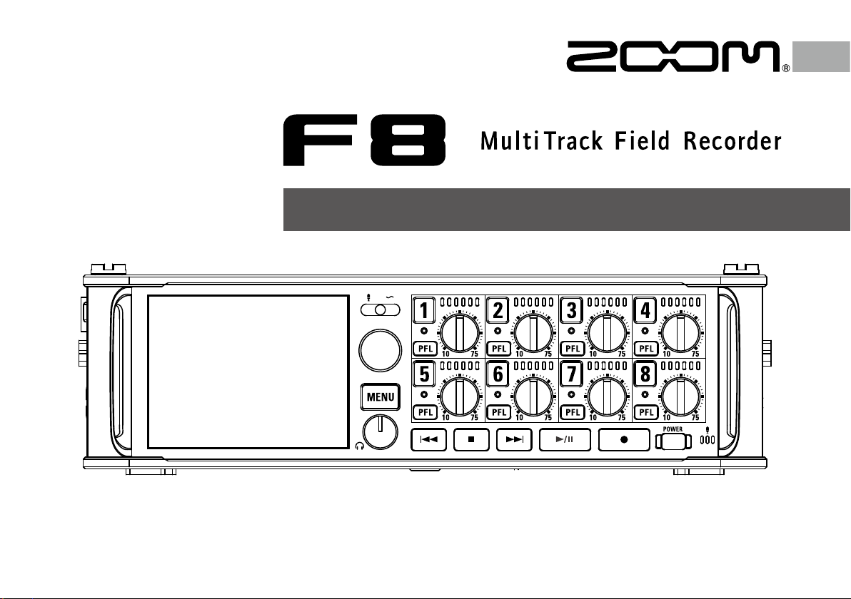
Operation Manual
© 2018 ZOOM CORPORATION
Copying or reprinting this manual in part or in
whole without permission is prohibited.
Page 2

Contents
Contents ...........................................................................................................02
Usage and Safety Precautions ........................................................................04
Introduction ......................................................................................................05
Names of parts .................................................................................................06
Connecting mics/other devices to Inputs 1–8................................................08
LCD display ...................................................................................................... 11
Preparations
Supplying power .............................................................................................15
Contents
Loading an SD card .........................................................................................17
Turning the power on and off .........................................................................18
Setting the date and time (Date/Time (RTC)).................................................19
Disabling the Automatic Power Saving function (Auto Power Off) .............21
Setting the power supply used (Power Source) ............................................22
Recording
Recording process ...........................................................................................24
Enabling recording on SD cards and setting file formats ............................25
Selecting inputs and adjusting levels ............................................................27
Recording .........................................................................................................29
Setting the sampling rate (Sample Rate) .......................................................30
Setting WAV file bit depth (WAV Bit Depth) ...................................................31
Setting MP3 file bit rate (MP3 Bit Rate)..........................................................32
Simultaneously recording tracks at different levels (Dual Channel Rec) ....33
Capturing audio before recording starts (Pre Rec) .......................................35
Maximum file size (File Max Size) ..................................................................36
Showing total recording times for long recordings (Time Counter) ...........37
Folder and file structure ..................................................................................38
Moving the previously recorded take to the FALSE TAKE folder .................40
Recording take settings
Changing the note for the next take recorded (Note) ...................................41
Setting how recorded scenes are named and numbered ............................43
Setting the take name reset condition and format .......................................46
Changing the track name of the next take recorded (Track Name) .............48
Changing the number of the next take recorded ..........................................50
02
Playback
Playing recordings ...........................................................................................51
Mixing takes .....................................................................................................52
Monitoring the playback signals of specific tracks during playback ...........53
Changing the playback mode (Play Mode) ....................................................54
Take and folder operations
Take and folder operations (FINDER) .............................................................55
Overview of take information (metadata) stored in files .............................62
Checking and editing take metadata ..............................................................64
Writing sound reports (Create Sound Report)...............................................71
Input settings
Input and output signal flow...........................................................................74
Adjusting the input signal monitoring balance.............................................75
Setting the track knob function (Track Knob Option) ....................................76
Adjusting the L/R track volume.......................................................................78
Monitoring the input signals of specific tracks (PFL/SOLO) .........................79
Setting the input source (Input Source) .........................................................80
Setting the monitoring volume on the PFL screen (PFL Mode) ...................81
Cutting low-frequency noise (HPF) ................................................................82
Input limiter ......................................................................................................83
Inverting the input phase (Phase Invert) ........................................................89
Changing the phantom power settings (Phantom) ......................................90
Changing the plugin power setting (Plugin Power) ......................................93
Delaying input signals (Input Delay) ..............................................................94
Converting mid-side input to ordinary stereo (Stereo Link Mode)..............95
Adjusting the input levels of multiple tracks simultaneously (Trim Link) ...97
Adjusting the side level of a mid-side mic capsule (Side Mic Level) ..........98
Changing the automatic mixing setting (Auto Mix) ....................................99
Setting the format of Ambisonic Mode .......................................................101
Setting the mic position used for ambisonic recording (Mic Position) .....106
Output settings
Setting signals sent to headphones (Headphone Routing) ........................108
Outputting alerts through headphones (Alert Tone Level) ..........................111
Setting the headphone output (Volume Curve) .......................................... 112
Page 3
F8 Multi Track Field Recorder
Boosting headphone output to alleviate interference from recorded sound
(Digital Boost) ................................................................................................ 113
Disabling outputs (Output On/Off) ............................................................... 114
Setting the standard output level (Output Level) ........................................ 11 5
Setting output levels .....................................................................................116
Delaying output signals (Output Delay)....................................................... 117
Output Limiter ................................................................................................ 118
Selecting signals sent to the main outputs (MAIN OUT Routing) .............122
Selecting signals sent to the sub outputs (SUB OUT Routing) .................123
Timecode
Timecode overview .......................................................................................124
Setting timecode functions ...........................................................................126
Setting automatic timecode recording delay (Auto Rec Delay Time) ........133
Setting timecode initialization used at startup (Start Timecode) ..............134
Slate mic/slate tone
Slate mic and slate tone overview ...............................................................136
Recording with the slate mic (Slate Mic) .....................................................137
Recording a slate tone (Slate Tone) ..............................................................140
Using USB functions
Exchanging data with a computer (SD Card Reader) .................................144
Using as an audio interface (Audio Interface) .............................................145
Using SD card recording and audio interface functions at the same time
(Audio Interface with Rec) ............................................................................147
Audio interface block diagrams ....................................................................149
Audio interface settings ................................................................................151
Using an
Using an as a controller (Connect) ...................................................152
Setting the type of keyboard connected to the
Setting
Setting user keys for the
Setting the power supply used by the
Setting the
Updating the
fader and knob operation (Knob/Fader Mode) ...................154
(User Key).................................................155
LED brightness (LED Brightness) ..................................157
firmware ......................................................................158
(Keyboard Type) ...153
(Power Source) ..................156
Various settings
Setting how timecode is shown (Home Timecode Display Size) ...............160
Setting level meter appearance (Level Meter) ............................................161
Setting the LED brightness (LED Brightness) ..............................................166
Making display settings (LCD) ......................................................................167
Adding marks when pausing (PLAY Key Option) ........................................170
Setting the keys held (Key Hold Target) .......................................................171
Other functions
Checking SD card information (Information) ..............................................172
Testing SD card performance (Performance Test) .......................................173
Formatting SD cards (Format) ......................................................................176
Checking the
Backing up and loading
Restoring default setting values (Factory Reset) .........................................180
Checking the firmware version (Firmware Version) ....................................181
Updating the firmware ..................................................................................182
Shortcut List ...............................................................177
settings (Backup/Load Settings) .............178
Appendices
Troubleshooting .............................................................................................183
Detailed product diagrams ...........................................................................184
Metadata list ..................................................................................................186
List of shortcuts .............................................................................................190
Specifications .................................................................................................19 2
Contents
03
Page 4
Usage and Safety Precautions
Usage and Safety Precautions
Safety Precautions
In this operation manual, symbols are used to
highlight warnings and cautions that you must
read to prevent accidents. The meanings of
these symbols are as follows.
Something that could cause
serious injury or death.
Something that could cause injury
or damage to the equipment.
Other symbols used
An action that is mandatory.
An action that is prohibited.
Warning
Operation using an AC adapter
Never use any AC adapter other than a
ZOOM AD-19.
Operation with external DC power supply
Use a 9V–16V external DC power supply.
Carefully study the warning indications of
the external DC power supply before use.
Operation with batteries
Use 8 commercially-available 1.5V AA bat-
teries (alkaline dry cell batteries, nickel
metal hydride batteries or lithium dry cell
batteries).
Carefully study the warning indications of
the batteries before use.
Always keep the battery cover closed
during use.
Alterations
Do not open the case or modify the prod-
uct.
04
Caution
Product handling
Do not drop, bump or apply excessive
force to the unit.
Be careful not to allow foreign objects or
liquids to enter the unit.
Operating environment
Do not use in extremely high or low tem-
peratures.
Do not use near heaters, stoves and other
heat sources.
Do not use in very high humidity or where
it could be splashed by water.
Do not use in places with frequent vibra-
tions.
Do not use in places with much dust or
sand.
AC adapter handling
When disconnecting the power plug from
an outlet, always pull on the plug itself.
Disconnect the power plug from the outlet
when the unit will not be used for
extended periods and whenever there is
lightning.
Battery handling
Install batteries with the correct +/− orien-
tations.
Use the specified batteries. Do not use
new and old batteries together. Do not use
batteries of different brands or types
together.
Remove the batteries when the unit will
not be used for extended periods.
If a leak occurs, thoroughly wipe the battery case and battery terminals to remove
the leaked fluid.
Danger of explosion if battery is incorrectly
replaced. Replace only with the same or
equivalent type.
A warning that batteries (battery pack or
batteries installed) shall not be exposed to
excessive heat such as sunshine, fire or
the like.
Mic handling
Always turn the power switch OFF before
connecting a mic. Do not apply unnecessary force when connecting a mic.
Attach the protective cap when no mic is
connected for extended periods.
Connection cables and input/output jacks
Always turn the power OFF for all equip-
ment before connecting any cables.
Always disconnect all connection cables
and the AC adapter before moving the unit.
Volume
Do not use at a loud volume for extended
periods.
Usage Precautions
Interference with other electrical equipment
In consideration of safety, the
designed to minimize its emission of electromagnetic waves and to suppress interference
from external electromagnetic waves. However, equipment that is very susceptible to
interference or that emits powerful electromagnetic waves could result in interference if
placed nearby. If this occurs, place the
and the other device farther apart.
With any type of electronic device that uses
digital control, including the
magnetic interference could cause malfunction, corrupt or destroy data and result in other
unexpected trouble. Always use caution.
Cleaning
Use a soft cloth to clean the exterior of the unit
if it becomes dirty. If necessary, use a damp
cloth that has been wrung out well to wipe it.
Never use abrasive cleansers, wax or solvents
such as alcohol, benzene or paint thinner.
Breakdown and malfunction
If the unit becomes broken or malfunctions,
immediately disconnect the AC adapter or DC
power supply, turn the power off and disconnect other cables. Contact the store where you
bought the unit or ZOOM service center with
the following information: product model,
serial number and specific symptoms of break-
has been
, electro-
down or malfunction, along with your name,
address and telephone number.
Copyrights
◎ Windows
or registered trademarks of Microsoft
ration.
◎ Macintosh, Mac OS and iPad are trademarks
or registered trademarks of Apple Inc.
◎ The SD, SDHC and SDXC logos are trademarks. MPEG Layer-3 audio compression technology is licensed from Fraunhofer IIS and Sisvel S.p.A.
◎ Bluetooth and the Bluetooth logo are registered trademarks of Bluetooth SIG, Inc. and are
used under license by ZOOM CORPORATION.
◎ Other product names, registered trademarks
and company names in this document are the
property of their respective companies.
Note: All trademarks and registered trade-
Recording from copyrighted sources, including
CDs, records, tapes, live performances, video
works and broadcasts, without permission of
the copyright holder for any purpose other than
personal use is prohibited by law.
ZOOM CORPORATION will not assume any
responsibility related to infringements of copyrights.
Note about the Auto Power Off function
The power will automatically turn off if unused
for 10 hours. If you want the power to instead
remain on, see "Disabling the Automatic Power
Saving function" on P.20 and turn the function
off.
®
and Windows® 7 are trademarks
marks in this document are for identification purposes only and are not
intended to infringe on the copyrights of
their respective owners.
®
Corpo-
Page 5
Introduction
F8 Multi Track Field Recorder
Thank you very much for purchasing a ZOOM Multitrack Field
Recorder. The
has the following features:
• 8 analog input channels with super high-quality preamps
The 8 lockable XLR/TRS combo jacks provide high-quality analog
inputs with EIN of −127 dBu or less, +75 dB maximum input gain and
support for +4 dB input.
• PCM recording at up to 192kHz/24-bit resolution
• Recording of up to 10 tracks simultaneously
Inputs 1–8 and a stereo mix (left and right) can be recorded at the
same time (8 tracks when the sampling rate is 192 kHz).
• Dual channel recording of separate files at lower levels
simultaneously with ordinary recording (Inputs 1–4)
Using dual channel recording at a lower input level, you can create
backup recordings to use when unexpected loud noise causes regular recordings to distort, for example.
• Newly redesigned limiters for overload protection
With 10 dB of headroom, this limiter prevents distortion even more
than ordinary ones. The threshold can also be set to keep the signal
below that level.
• Time code with pinpoint accuracy
The utilizes a high-precision oscillator that generates timecode with accuracy of 0.2ppm, ensuring rock-solid stability when
syncing audio and video.
• Outputs include a stereo headphone jack with a powerful
100mW amp as well as MAIN OUT 1/2 and SUB OUT 1/2
jacks
This allows you to send the audio signal to a video camera or other
device while monitoring with headphones.
• Built-in digital mixer with flexible signal routing
Prefader and postfader signals from inputs 1–8 can be freely routed
to any outputs.
• Phantom power (+24V/+48V) can be supplied
This can be turned on/off for each input separately.
• Three possible power sources—batteries, an AC adapter and
an external DC power supply
In addition to AA batteries and an AC adapter, a 9-16V external DC
power supply can also be used.
• Double SDXC card slots
Simultaneous recording on 2 SD cards is possible, and support for
SDXC cards up to 512 GB enables long-duration recording. In addition, the
computer using USB.
can be used as a card reader by connecting to a
• USB audio interface capabilities with up to 8 ins and 4 outs
The can be used not only as a 2-in/2-out audio interface, but
also as an 8-in/4-out audio interface (driver required for Windows).
• Other useful features
Other convenient functions include a built-in slate mic for voice
memos and a variable frequency slate tone generator to confirm levels. There are also input and output delays and pre-recording of up to
6 seconds.
• ZOOM mic capsules can be connected
Use any ZOOM mic capsule instead of inputs 1/2.
Please read this manual carefully to fully understand the functions of
the
After reading this manual, please keep it with the warranty in a safe
place.
so that you can make the most of it for many years.
Introduction
05
Page 6
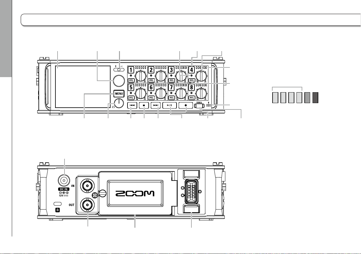
Front
connector
connectors
LED level
Names of parts
Display
Select
encoder
Slate
switch
Track
indicator
Track
key
Track
knob
meter
Names of parts
MENU
key
Headphone
volume
Search
backward
key
Stop
key
Search
forward
key
Play/pause
key
Record
key
PFL key
Slate mic
POWER
switch
LED level meter
Green Orange Red
−48
−30 −18 −12 −6 0
(dBFS)
Back
DC IN connector
Battery slotTimecode IN/OUT
MIC IN
06
Page 7
F8 Multi Track Field Recorder
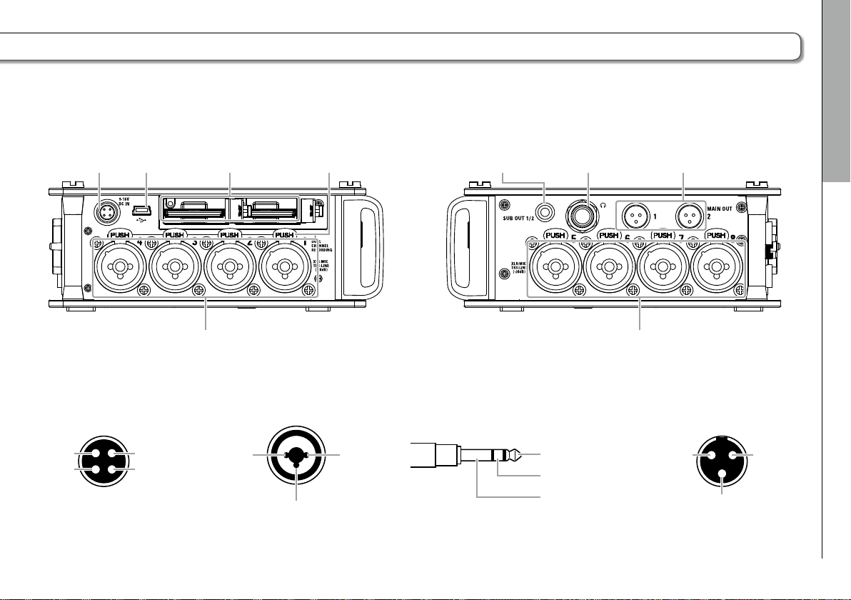
Left side
XLR TA3TRS
Right side
3: COLD
HIROSE 4-pin
EXT DC IN
connector
DC 9–16V
USB
port
1: −4: +
2: NC3: NC
SD card
Inputs 1–4
slots
Lock release
button
3
SUB OUT 1/2
jack
Headphone
jack
MAIN OUT 1/2
jacks
Inputs 5–8
Inputs 1–8EXT DC IN MAIN OUT
12
1: GND
2: HOT
3: COLD
TIP: HOT
RING: COLD
SLEEVE: GND
2
Names of parts
31
1: GND
2: HOT
07
Page 8
(XLR cable)
(XLR cable)
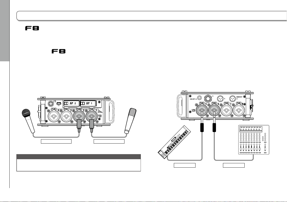
Connecting mics/other devices to Inputs 1–8
The can record a total of 10 tracks simultaneously: 8 individual tracks with signals coming from Inputs 1–8 and a stereo
mix of these inputs on left and right tracks.
You can connect mics and the outputs of line-level devices such as keyboards, mixers, or instruments with active electronics
to Inputs 1–8 and record them to tracks 1–8. Alternatively, Inputs 1 and 2 can instead receive input from a ZOOM mic capsule
connected to the
MIC IN connector.
Connecting mics
Connecting mics/other devices to Inputs 1–8
Connect dynamic and condenser mics with XLR plugs to
Inputs 1–8.
Phantom power (+24V/+48V) can be supplied to condenser
mics. (→ P.90)
Dynamic mic
NOTE
When disconnecting a mic, gently pull on the XLR plug while simul-
taneously pushing the connector lock release button.
Condenser mic
08
Connecting line level equipment
Connect the TRS plugs of keyboards and mixers directly to
Inputs 1–8.
Direct input of passive guitars and basses is not supported.
Connect these instruments through a mixer or effects device.
Keyboard
(TRS cable)
Mixer
(TRS cable)
Page 9
F8 Multi Track Field Recorder
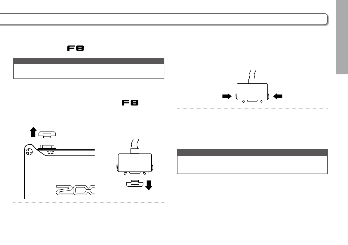
Connecting mic capsules
A ZOOM mic capsule can be connected to the MIC IN connector on the back of the
NOTE
• The mic capsule input is assigned to tracks 1/2.
• When a mic capsule is connected, Inputs 1/2 cannot be used.
Connecting and disconnecting mic capsules
.
1. Remove the protective caps from the and the
mic capsule or extension cable.
2. While pressing the side buttons on the mic capsule or
extension cable, connect it to the main unit, inserting
it completely.
3. To disconnect the mic capsule or extension cable, pull
it away from the main unit while simultaneously
pressing the buttons on its sides.
NOTE
• Do not use too much force when disconnecting. Doing so could
damage the mic capsule, extension cable or main unit.
• Reattach the protective cap when a mic capsule is not connected.
Stereo input
By enabling the stereo link for tracks 1/2, 3/4, 5/6 or 7/8, the
corresponding Inputs (1/2, 3/4, 5/6 or 7/8) can be handled as a
stereo pair. (→ P.27)
When linked, Input 1, 3, 5 or 7 becomes the left channel and
Input 2, 4, 6 or 8 becomes the right channel.
Connecting mics/other devices to Inputs 1–8
09
Page 10
Connecting mics/other devices to Inputs 1–8 (continued)
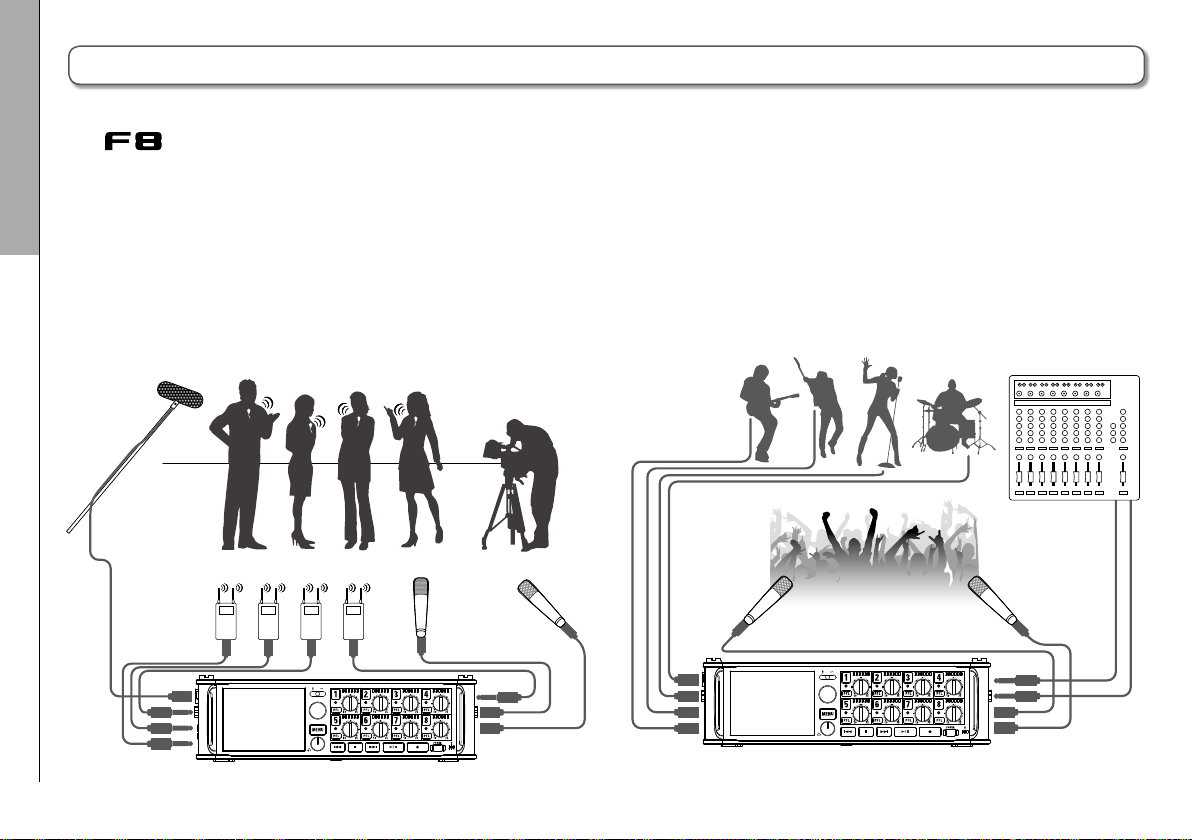
Connection examples
The allows you to record in a variety of situations, such as the following.
While filming
• Input 1: gun mic for main subject sound (XLR connection)
• Inputs 2–5: wireless lavalier mics for performers (TRS
Connecting mics/other devices to Inputs 1–8
connections)
• Inputs 6-7: mics for ambient sound (XLR connections)
Gun mic
1
2
3
4
Wireless lavalier mics
Lavalier receivers
Ambient
mics
6
7
Concert recording
• Inputs 1-4: mics for stage performance (XLR connections)
• Inputs 5-6: line-level PA mixer outputs (TRS connections)
• Inputs 7-8: mics for audience sound (XLR connections)
Vocal mic, etc.
PA mixer
Audience mics
1
5
2
3
4
5
6
7
8
10
Page 11
LCD display
F8 Multi Track Field Recorder
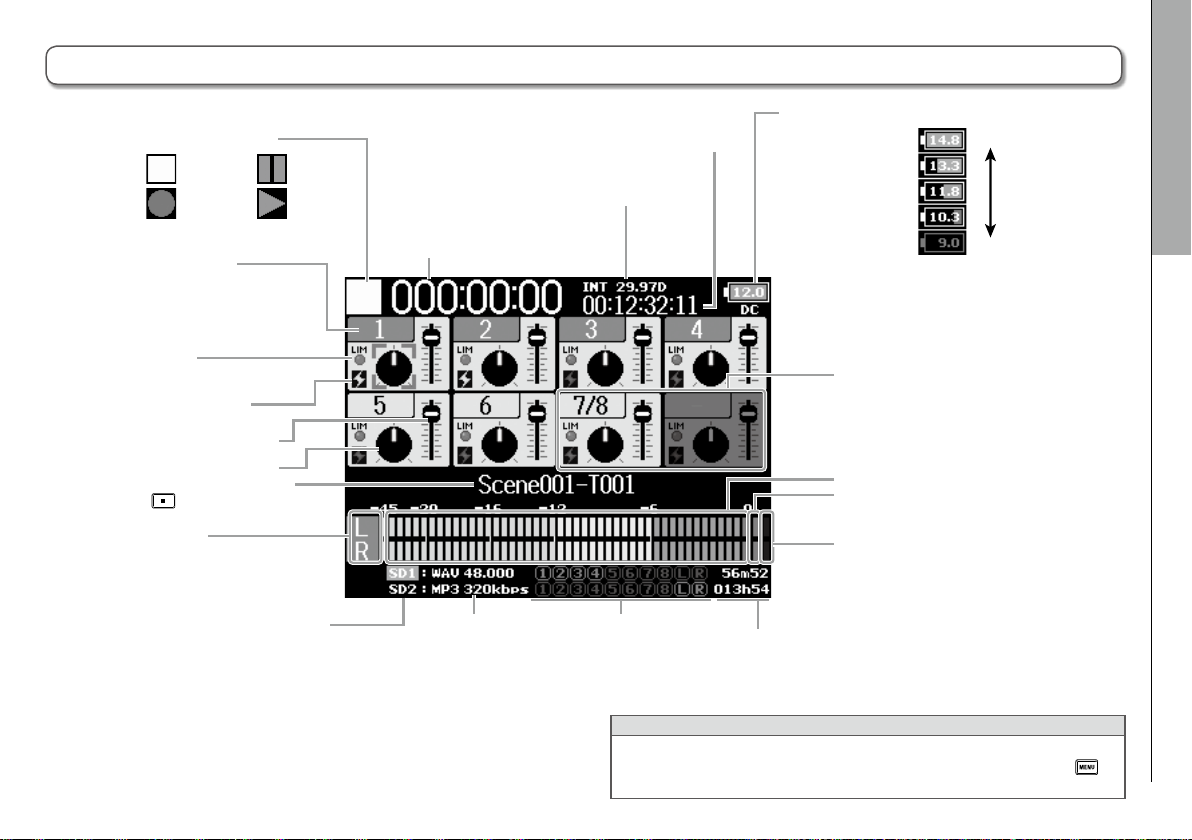
Home Screen
■ Mixer
Limiter status
Grey: disabled
Red: enabled
Yellow: functioning
Phantom power status
Lit: enabled
Unlit: disabled
Recording/playback take name
Press when stopped to show the
name of the next track to be recorded.
L/R tracks
Status icon
Stopped
Recording
Track number
Red: input enabled
Green: playback track enabled
Grey: input disabled
Paused
Playing
Fader
Pan
Playback card
Green: used for playback
Grey: no card
Frame rate
INT: internal timecode enabled
EXT: external input timecode enabled
Counter
(playback/elapsed recording time)
Recording/playback
file format and
sampling rate
(by card)
Recording/playback tracks
Red: recording tracks
Green: playback tracks
Grey: disabled tracks
(by card)
Recording/playback timecode
Power type and remaining power
DC: AC adapter
EXT: external DC
power supply
AA: batteries
Stereo-linked
inputs
Level meters
Clip indicators
Limiter indicators
Yellow: limiter functioning
When recording: remaining recordable time
When playing: remaining playback time
(by card)
Full
Empty
LCD display
HINT
• Stereo-linked tracks are shown together, for example, "7/8".
• When the Home Screen is not displayed, press and hold
return to the Home Screen.
to
11
Page 12
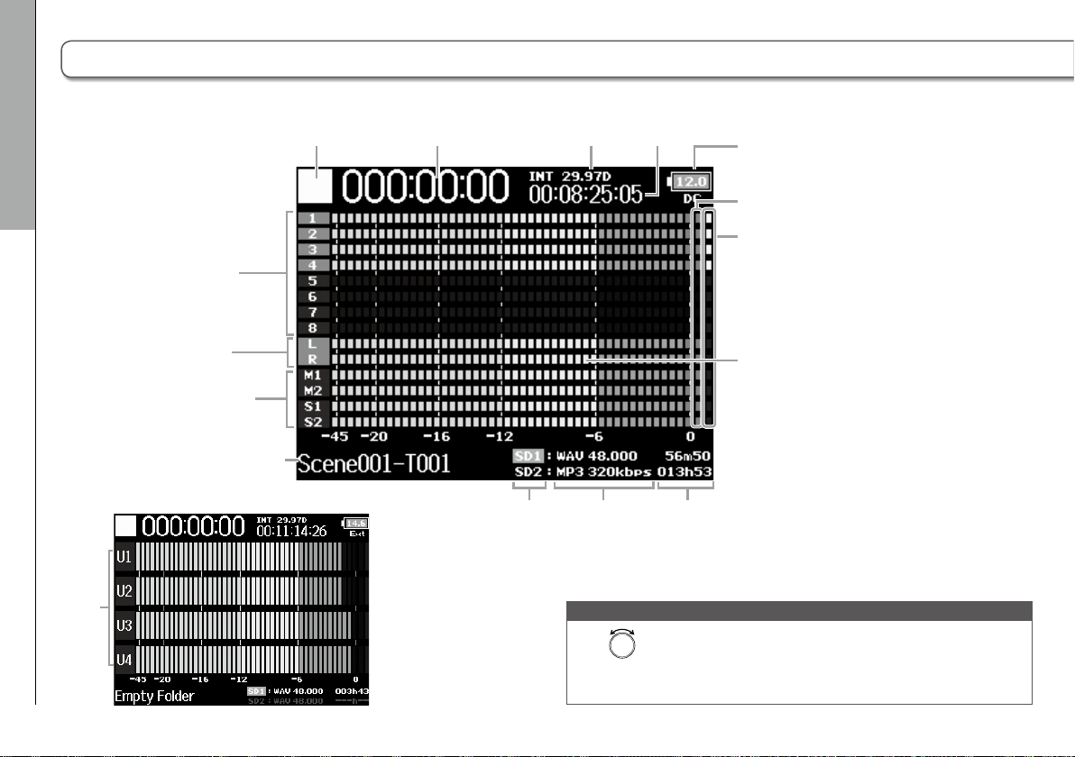
■ Level meters
USB1-4
LCD display
LCD display (continued)
Status icon Counter Frame rate
Tracks 1–8
Recording/playback
timecode
Power type and
remaining power
Clip indicators
Limiter
indicators
12
L/R tracks
MAIN OUT 1/2,
SUB OUT 1/2
tracks
Recording/playback
take name
Playback
card
Level
meters
Recording/playback
file format and
sampling rate
(by card)
When recording: remaining recordable time
When playing: remaining playback time
(by card)
NOTE
Turn
to switch the mixer display (Tracks 1–8, MAIN OUT 1/2,
SUB OUT 1/2, USB1−4) or level meter display (Views 1–4 can be set
→ P.163) shown on the LCD.
Page 13
F8 Multi Track Field Recorder
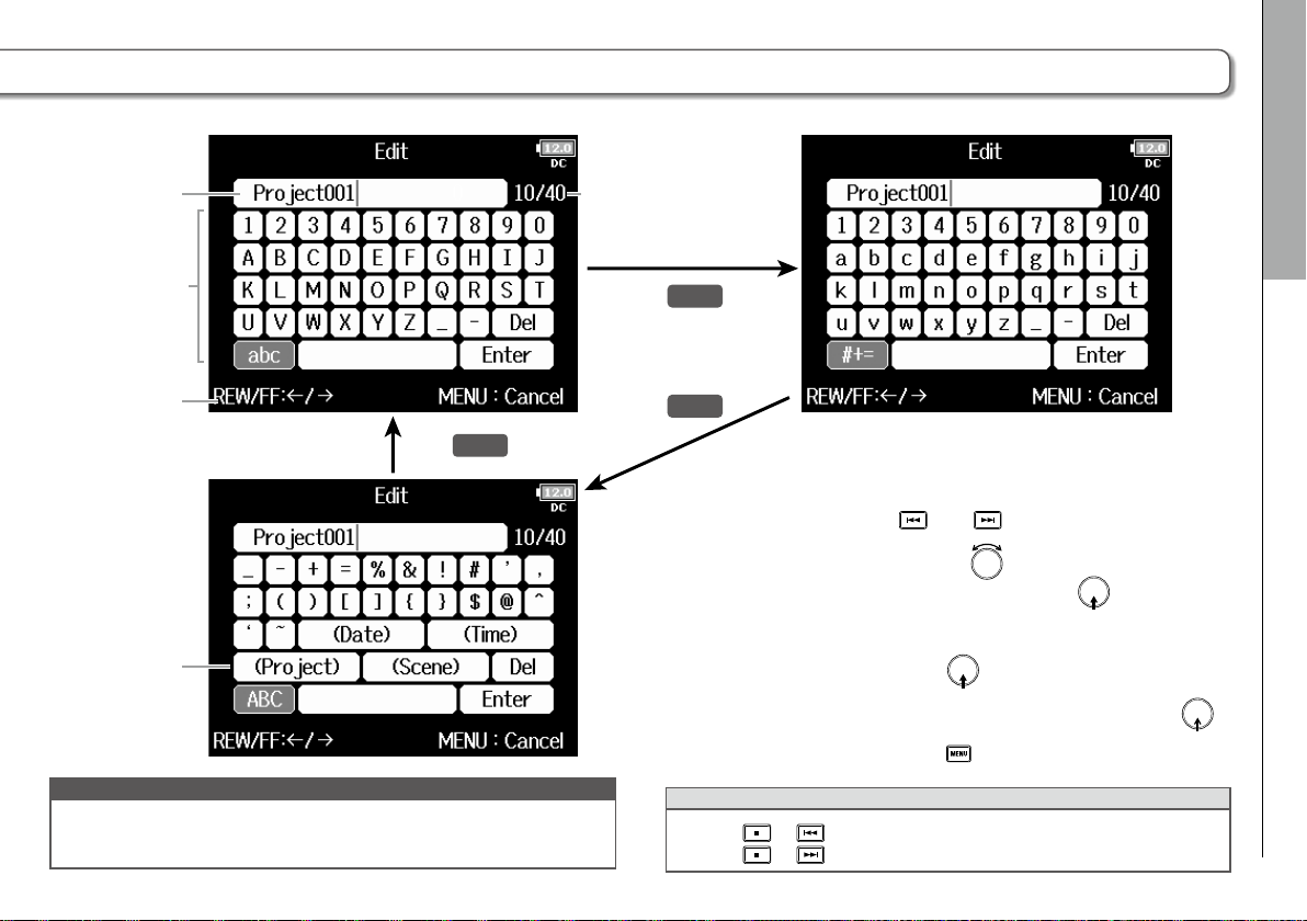
Character input screen
Text box
Keyboard
Instructions
Automatic
input keys
NOTE
• The following characters can be used in project names:
(space) ! # $ ' ( ) + , - 0 1 2 3 4 5 6 7 8 9 ; = @ A B C D E F G H I J K L M N O P Q R S T U
V W X Y Z [ ] ^ _ ` a b c d e f g h i j k l m n o p q r s t u v w x y z { } ~
Press
MENU::
ABC
Number of characters input/
Maximum number of characters
Press
abc
Press
#+=
■ Editing operations
Move cursor in box: and
Character selection:
Confirm character: Press
Complete editing: Move cursor to “Enter” and press
Cancel editing: Press
HINT
• Press
• Press + to move the cursor to “Enter”.
Turn the
to move horizontally and
turn it while pressing
cally
+ to delete the previous character.
LCD display
to move verti-
13
Page 14

LCD display (continued)
■ Automatic input keys
LCD display
(Date): Automatically inputs the date. Example: 150210
(Time): Automatically inputs the time. Example: 180950
(Project): Automatically inputs “Project***” in the field.
(Scene): Automatically inputs the scene name.
14
Page 15
F8 Multi Track Field Recorder
Supplying power
Using AA batteries
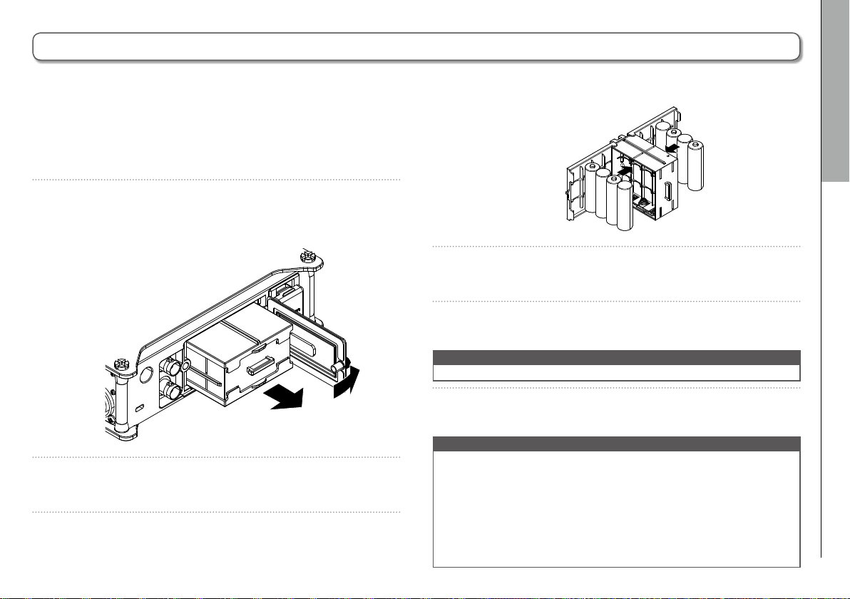
1. Turn the power off and then loosen the screw in the
battery cover to open it.
2. Remove the battery case from the battery slot.
3. Open the battery case cover.
4. Install the batteries.
−
+
−
+
+
−
+
−
−
+
−
+
+
−
5. Replace the battery case cover.
6. Load the battery case.
NOTE
Load the case so that the side with the protruding rail is up.
7. Close the battery cover and tighten the screw.
NOTE
• Be careful because the battery case could become loose unex-
pectedly if the cover screw is not tightened firmly.
• Use only one type of batteries (alkaline, NiMH or lithium) at a
time.
• After loading batteries, set "Power Source" to the correct type of
battery. (→ P.22)
• If the remaining battery power indicator turns red, turn the power
off immediately and install new batteries.
Preparations
Supplying power
15
Page 16
Preparations
Supplying power (continued)
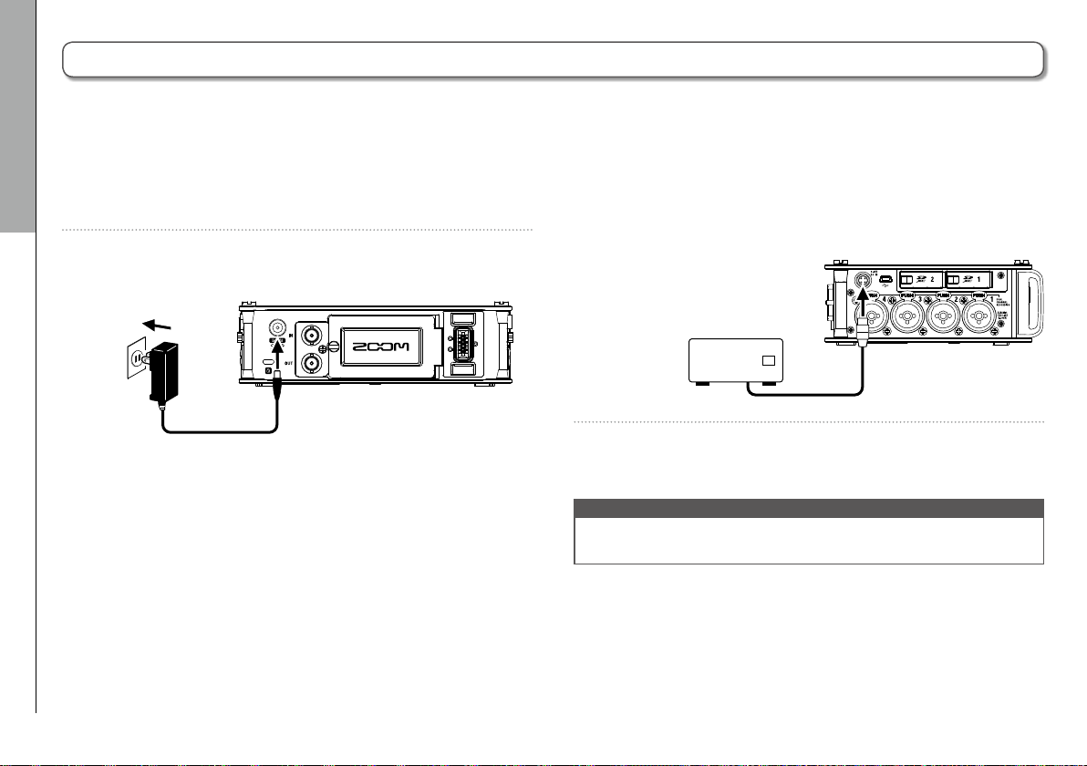
Using an AC adapter
1. Connect the dedicated AC adapter to the DC IN
connector.
Supplying power
2. Plug the dedicated AC adapter into an outlet.
Using an external DC power supply
1. Connect the external DC power supply equipment to
the EXT DC IN connector.
Connect a 9–16V direct-current power supply.
2. If there is an adapter, plug the adapter into an outlet.
NOTE
• When connecting an external DC power supply, be sure to make
the power supply settings. (→ P.22)
16
Page 17
F8 Multi Track Field Recorder
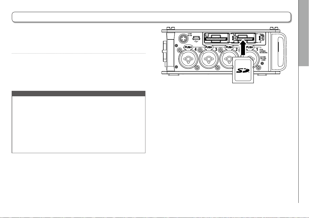
Loading an SD card
1. Turn the power off and then open the SD card slot
cover.
2. Insert the SD card into the SD CARD 1 or 2 slot.
To eject an SD card:
Push the card further into the slot until it clicks and then
pull it out.
NOTE
• Always turn the power off before inserting or removing an SD
card. Inserting or removing a card while the power is on could
result in data loss.
• When inserting an SD card, be sure to insert the correct end with
the top side up as shown.
• If an SD card is not loaded, recording and playback will not be
possible.
• To format an SD card, see P. 176.
Preparations
Loading an SD card
17
Page 18
Preparations
Turning the power on and off
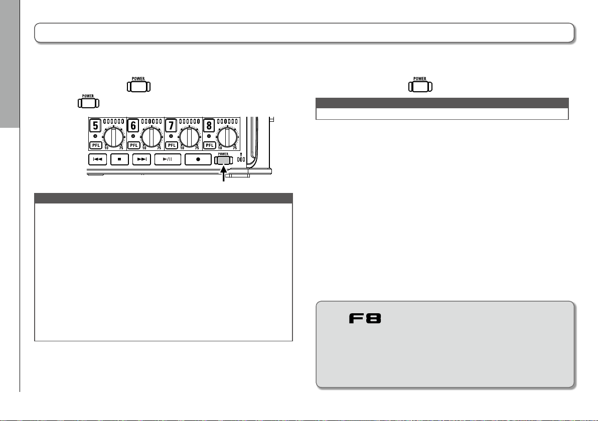
Turning the power on
1. Press and hold briefly.
The LED will light.
Turning the power on and off
NOTE
• The first time you turn the power on after purchase, you must
set the date/time (→ P. 19). You can also change this setting later.
• If “No Card!” appears on the display, confirm that an SD card is
inserted properly.
• If “Card Protected!” appears on the display, the SD card write-pro-
tection is enabled. Slide the lock switch on the SD card to disable
write-protection.
• If “Invalid Card!” appears on the display, the card is not format-
ted correctly. Format the card or use a different card. To format an
SD card, see P. 176.
Turning the power off
1. Press and hold briefly.
NOTE
Keep pressing it until the ZOOM logo appears on the LCD.
The will automatically turn off if
it is unused for 10 hours.
To keep the power on continuously until powered off, see "Dis-
abling the Automatic Power Saving function" on P.21 and set Auto
Power OFF to Off.
18
Page 19
F8 Multi Track Field Recorder
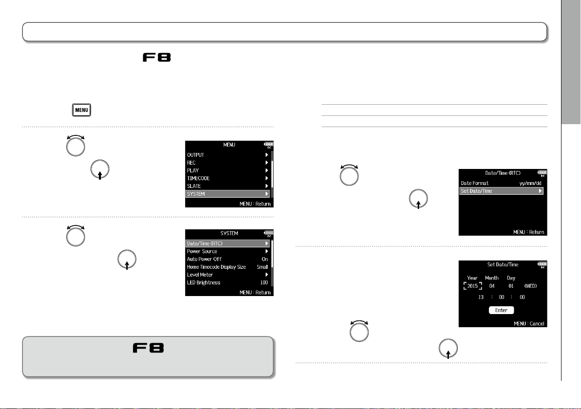
Setting the date and time (Date/Time (RTC))
The date and time set on the are used when recording files, for example.
You can also set the date format (order of year, month and day).
▶ Continue to one of the following procedures.
1. Press .
2. Use to select
and press
.
3. Use to select
(RTC)
, and press .
SYSTEM
,
Date/Time
Setting the date and time .................................................P. 1 9
Setting the date format .....................................................P.20
Setting the date and time
4. Use to select
Date/Time
5. Change the setting.
■ Changing settings
Move cursor or change value:
Preparations
Setting the date and time (Date/Time (RTC))
Set
, and press .
The first time you turn the on after purchasing it, you
must set the date/time.
Turn
Select item to change: Press
19
Page 20
Preparations
Setting the date and time (Date/Time (RTC)) (continued)
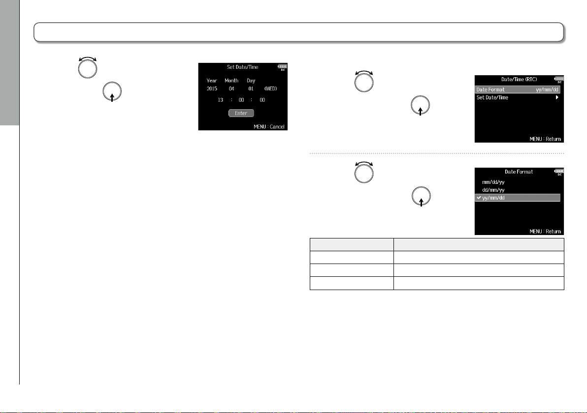
6. Use to select
and press
This completes setting the date
Setting the date and time (Date/Time (RTC))
and time.
.
Enter
,
Setting the date format
4. Use to select
Format
, and press .
Date
5. Use to select the
20
format, and press
Setting value Explanation
mm/dd/yy Month, day, year order
dd/mm/yy Day, month, year order
yy/mm/dd Year, month, day order
.
Page 21
F8 Multi Track Field Recorder
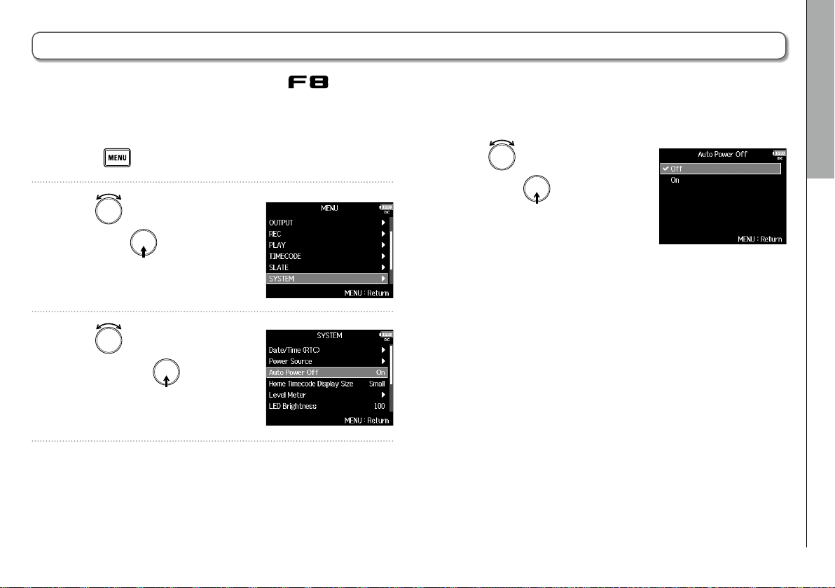
Disabling the Automatic Power Saving function (Auto Power Off)
The power will automatically turn off if the is unused for 10 hours.
If you want the power to stay on continuously until powered off, disable the Automatic Power Saving function.
1. Press .
2. Use to select
and press
.
3. Use to select
Off
and press .
SYSTEM
,
Auto Power
4. Use to select
and press
.
Off
,
Preparations
Disabling the Automatic Power Saving function (Auto Power Off)
21
Page 22
Preparations
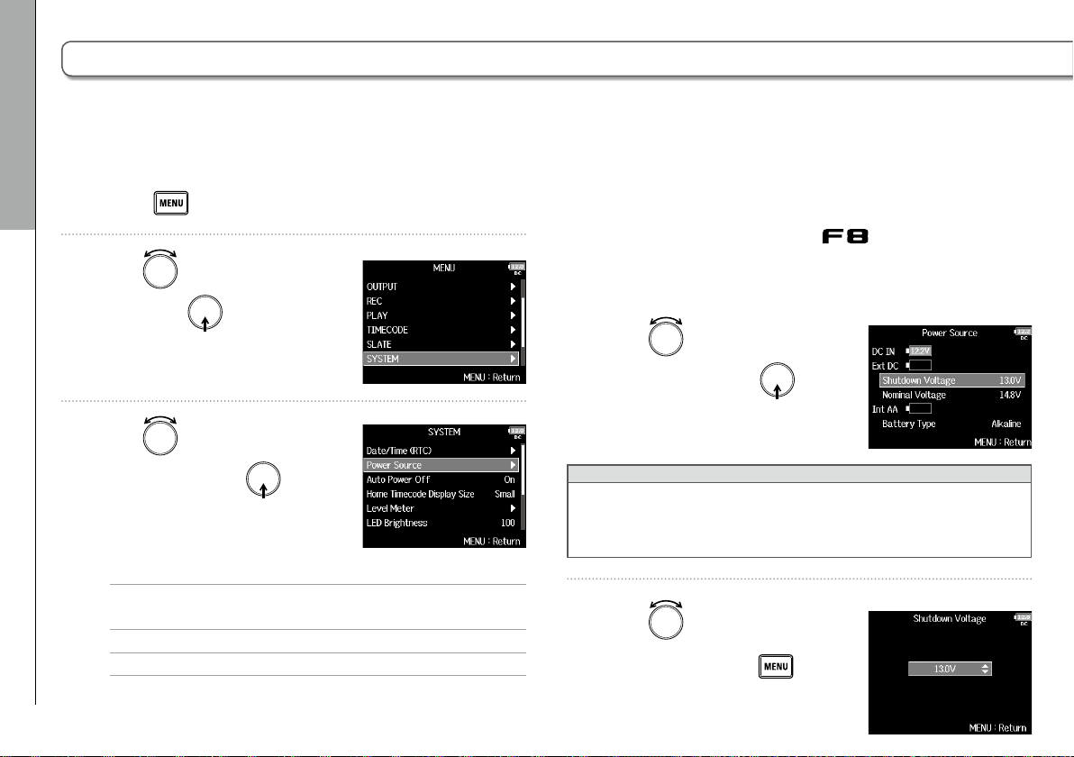
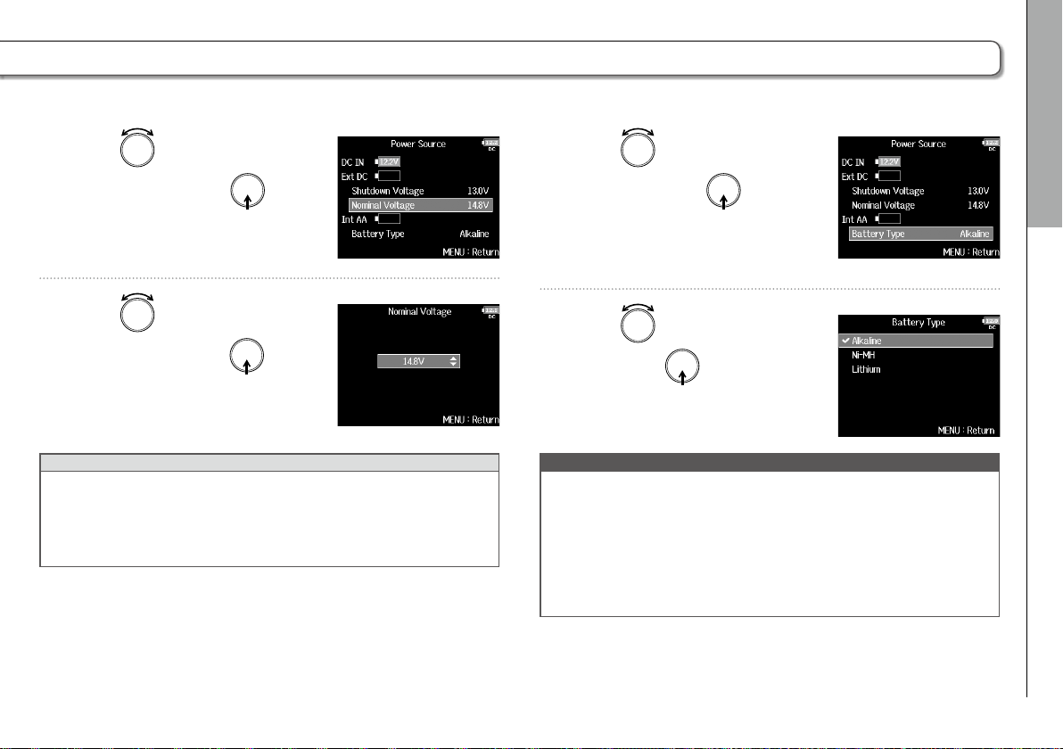
Setting the power supply used (Power Source)
Set the external DC power supply shutdown voltage, nominal voltage and type of batteries so that the remaining power supply
charge can be shown accurately.
On this menu page, you can also check the voltage of each power supply and the remaining battery capacity.
Setting the external DC power supply (Ext DC) shut-
1. Press .
Setting the power supply used (Power Source)
2. Use to select
and press
.
SYSTEM
,
down voltage
When an external DC power supply is being used, if the voltage
drops below the value set here, the will automatically stop
recording and turn off.
If AA batteries (Int AA) are installed, however, the power supply will
switch to Int AA and operation will continue.
4. Use to select
Shutdown
3. Use to select
Source
, and press .
▶ Continue to one of the following procedures.
Setting the external DC power supply (Ext DC) shutdown
voltage .........................................P.22
Setting DC power supply (Ext DC) nominal voltage.....P.23
Setting the AA battery type (Int AA)..................P.23
22
Power
Voltage
HINT
• The shutdown voltage is the voltage when the external DC power
supply runs out and can no longer supply power.
• See the manual for the external DC power supply for the shutdown voltage value.
, and press .
5. Use to select the
voltage, and press
.
Page 23
F8 Multi Track Field Recorder
Preparations
Setting DC power supply (Ext DC) nominal voltage
4. Use to select
Voltage
, and press .
Nominal
5. Use to select the
voltage, and press
HINT
• The nominal voltage is the voltage of the external DC power sup-
ply under normal conditions. This value should be indicated on
the outside of the external DC power supply.
• This can be set from 12.0 to 15.0 V in 0.2 V intervals.
.
Setting the AA battery type (Int AA)
4. Use to select
Type
, and press .
Battery
5. Use to select the type,
and press
NOTE
• When multiple power supplies are connected, they will be used
in the following order of precedence.
1. Dedicated AC adapter (DC IN)
2. External DC power supply (Ext DC)
3. AA batteries in unit (Int AA)
• The voltages of each power supply are shown on the display.
.
Setting the power supply used (Power Source)
23
Page 24
Recording
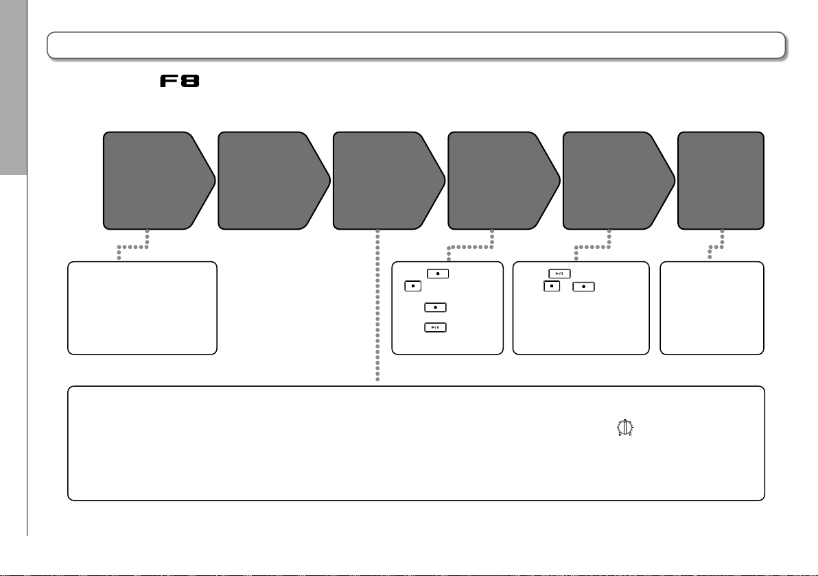
Recording process
Recording with the follows the process shown below.
The data created for each recording occurrence is called a "take".
Recording process
• Connect mics, instruments,
audiovisual equipment and
other devices to Inputs 1–8.
(→ P.8)
• Connect a mic capsule to the
MIC IN connector. (→ P.9)
1. Set the SD card and file format
• Set the recording file format for each
SD card separately.
24
Connect
for recording. (→ P.25)
Turn power
on (→ P.18)
Prepare before
recording
2. Select the recording tracks
(→ P.27)
• Use track keys to select.
The indicators for selected tracks light
red and you will be able to monitor
input sounds.
• Press two track keys simultaneously
to link them as a stereo track.
Record
(→ P.29)
• Press to start and
to stop recording.
• You can also set marks.
• Press to start
recording a new track.
• Press to pause
3. Make recording settings
• Make other settings, including for the
following functions:
- dual channel recording (→ P.33)
- pre recording (→ P.35)
- high pass filter (→ P.82)
- limiter (→ P.83)
• Press to start playback
and or to stop it.
• Marks, for example, can also
be set.
Play back
and check
(→ P.51)
Check take
information
(→ P.63)
• Check and edit
metadata.
4. Adjust the input levels
(→ P.28)
• Use to adjust each input.
• The side mic level can also be
adjusted when using a mid-side mic
capsule.
Page 25
F8 Multi Track Field Recorder
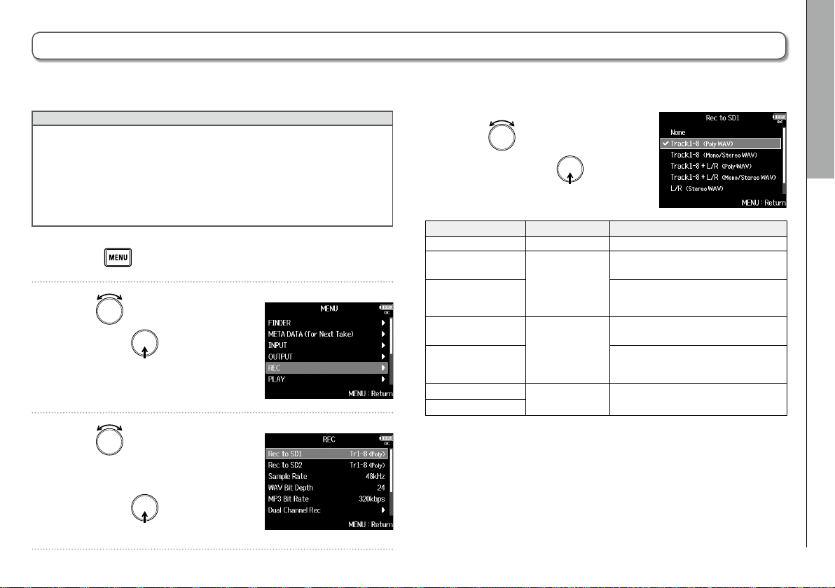
Enabling recording on SD cards and setting file formats
The recording file format can be set independently for SD CARD slots 1 and 2.
HINT
• Recording the same content to two cards is possible by using
the same settings for both card slots. This function can be used
to create a backup in case the sound skips on one card, for
example.
• You can also record tracks 1–8 unmixed on one SD card while
recording all tracks mixed together as MP3 or WAV data with left
and right tracks.
1. Press .
2. Use to select
and press
REC
,
.
4. Use to select the file
type, and press
Setting value Tracks recorded Explanation
None – Nothing is recorded on the SD card.
Track1-8
(Poly WAV)
Track1-8
(Mono/Stereo WAV)
Track1-8 + L/R
(Poly WAV)
Track1-8 + L/R
(Mono/Stereo WAV)
L/R (Stereo WAV)
L/R (Stereo MP3)
Selected tracks
1–8
All selected
tracks
L/R tracks
3. Use to select
Recording
.
Enabling recording on SD cards and setting file formats
A single (multitrack) file is created that
contains audio for multiple tracks.
A single mono file is created for
each mono track and a single stereo
file is created for each stereo track.
A single (multitrack) file is created that
contains audio for multiple tracks.
A single mono file is created for
each mono track and a single stereo
file is created for each stereo track.
A stereo file is created based on the
mix created by the internal mixer.
Rec to SD1
or
and press
Rec to SD2
,
.
25
Page 26
Recording
Enabling recording on SD cards and setting file formats
Enabling recording on SD cards and setting file formats (continued)
NOTE
• When recording with a Mono/Stereo WAV setting, the audio files
are saved in a take folder that is created. (→ P.38)
• When recording to 2 SD cards simultaneously, files will be saved
in take folders with the same name on both cards. Folders will be
created automatically if they do not already exist.
• If recording should stop on one SD card because, for example, it
runs out of space, recording will continue on the other SD card.
At such times, do not remove the card that has stopped recording
from the slot. Doing so could damage the card or data.
26
Page 27
F8 Multi Track Field Recorder
Selecting inputs and adjusting levels
You can select which of Inputs 1–8 to use. Inputs will be recorded on tracks with the same numbers. For example, Input 1 will
be recorded on track 1 and Input 2 will be recorded on track 2.
Selecting inputs
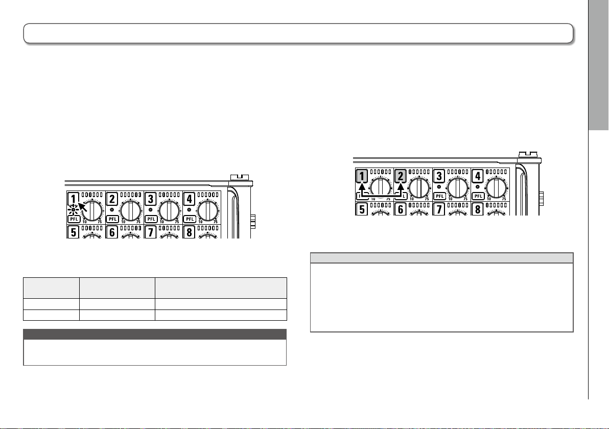
1. Make the track indicator light by pressing the track
key for the number of the input to record.
The background color of the track number on the LCD also
changes at this time.
Track indicator
Lit red Red The input is enabled.
Unlit Gray The input is disabled.
NOTE
The signals from the inputs selected this way will also be sent to
the L/R tracks.
Track number
background color
Explanation
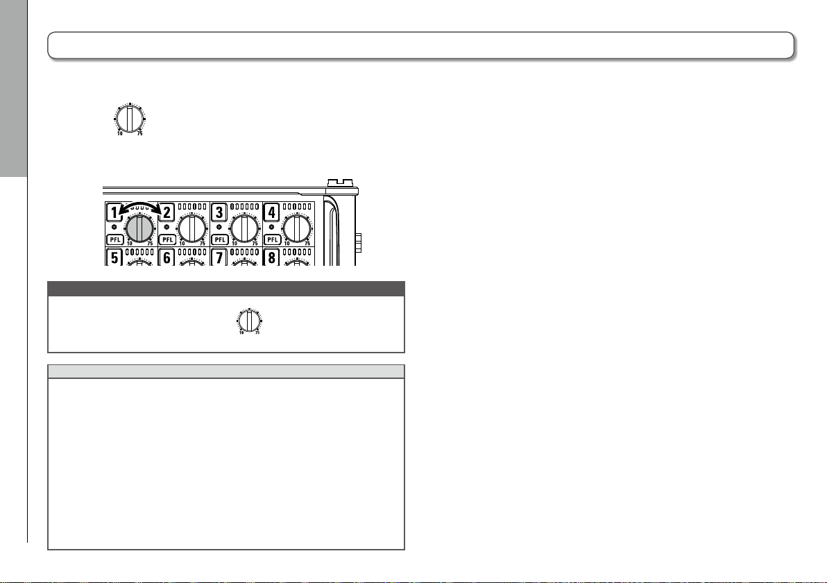
Linking inputs as a stereo pair
1. While pressing track key 1, press track key 2.
Tracks 1 and 2 will be linked as a stereo track (stereo link).
Repeat the same procedure to disable the stereo link.
HINT
• The 3/4, 5/6 and 7/8 track pairs can also be stereo-linked in the
same way.
• When a mic capsule that allows independent L and R input selec-
tion is connected, stereo-linking can also be enabled and dis-
abled for those tracks.
Recording
Selecting inputs and adjusting levels
27
Page 28
Recording
Selecting inputs and adjusting levels (continued)
Adjusting input levels
1. Turn for the selected track to adjust its input
level.
Selecting inputs and adjusting levels
NOTE
When a mic capsule is connected,
Use the level control on the mic capsule to adjust its input volume.
HINT
• Inputs connected with XLR plugs can be set from +10 to +75 dB,
and inputs connected with TRS plugs can be set from −10 to +55
dB. Tracks with the USB set as the input source can be set from
−35 to +30 dB.
• If the sound distorts even when you lower the input level, try
changing mic positions and adjusting the output levels of con-
nected devices.
• Using the limiter (→ P.83)
• Using the high pass filter (→ P.82)
for Inputs 1/2 is disabled.
28
Page 29
F8 Multi Track Field Recorder
Recording
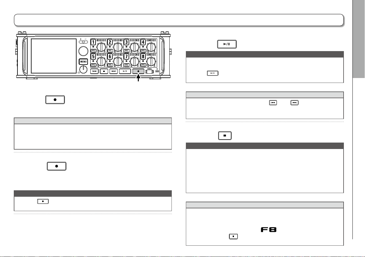
1. Press .
This starts recording.
HINT
If the timecode function is enabled, recording will start from frame
00 (00 or 02 when using drop frame) and files will always end
exactly on a second. This makes synchronization easy when editing
later.
2. Press to start a new take when recording.
This will end the current take and start a new take while
continuing to record without interruption.
NOTE
Pressing
at least a second.
during recording is only possible after recording for
3. Press to pause.
NOTE
• When pausing, pausing will occur at a whole second increment.
• When recording is paused, a mark is added at that point.
Press
• A maximum of 99 marks can be added to a take.
HINT
• During playback, you can press
where marks have been added.
• You can also add marks without pausing. (→ P. 169)
to resume recording.
and to jump to points
4. Press to stop.
NOTE
• If the maximum file size is exceeded during recording (→ P.36),
recording will continue in a new take with a number that is one
higher. No gap in sound will occur between the two takes when
this happens.
• When recording on 2 SD cards simultaneously, if recording
should stop on one because it runs out of space, recording will
continue on the other SD card without interruption.
HINT
• Files are automatically saved at regular intervals during record-
ing. Even if the power is interrupted or another unexpected problem occurs during recording, an affected file can be restored to
normal by playing it with the
• Press and hold when the HOME screen is open to check the
name that will be given to the next take recorded.
.
Recording
Recording
29
Page 30
Recording
Setting the sampling rate (Sample Rate)
You can set the sampling rate used to record files.
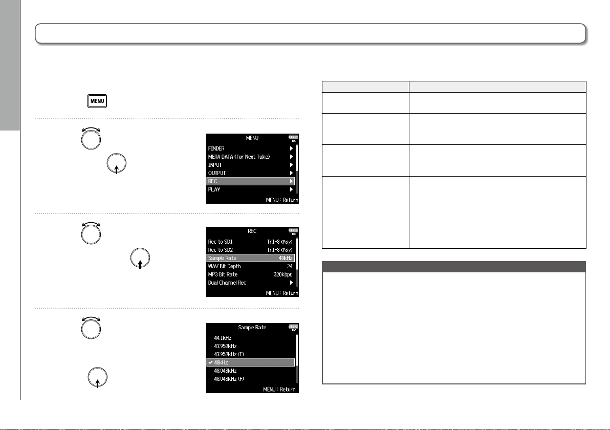
1. Press .
Setting the sampling rate (Sample Rate)
2. Use to select
and press
3. Use to select
Rate
, and press .
REC
.
Sample
,
4. Use to select the
sampling rate, and
press
.
Setting value Explanation
44.1kHz, 48kHz,
88.2kHz, 96kHz, 192kHz
47.952kHz
48.048kHz
47.952kHz (F),
48.048kHz (F)
NOTE
• When the recording file format is MP3, only 44.1kHz and 48kHz
can be selected.
• When 192 kHz is selected, L/R tracks will not be recorded. The
Input Delay and Output Delay are also disabled. Moreover,
Auto Mix, Ambisonic Mode, and Input Limiter > On/Off > On
(Advanced) cannot be set.
• Audio Interface with Rec cannot be used when values other than
44.1 kHz or 48 kHz are selected.
These are standard sampling rates.
Select this when recording video at 23.976 frames
per second if you want to edit at 24 frames per
second later.
Select this when recording video at 24 frames per
second if you want to edit at NTSC 29.97 or 23.98
HD later.
These function the same as the two above, but the
<FILE_SAMPLE_RATE> sampling rate metadata
will be recorded as 48kHz.
This enables playback and editing with devices
and software that do not support 47.952kHz and
48.048kHz WAV files. Playback, however, will occur
at the ±0.1% speed at which the file was recorded.
30
Page 31

F8 Multi Track Field Recorder
Setting WAV file bit depth (WAV Bit Depth)
You can set the bit depth of WAV files.
1. Press .
2. Use to select
and press
3. Use to select
Depth
, and press .
REC
.
WAV Bit
,
4. Use to select the bit
depth, and press
HINT
This can be set to 16-bit or 24-bit.
.
Recording
Setting WAV file bit depth (WAV Bit Depth)
31
Page 32

Recording
Setting MP3 file bit rate (MP3 Bit Rate)
You can set the bit rate of recorded MP3 files.
1. Press .
Setting MP3 file bit rate (MP3 Bit Rate)
2. Use to select
and press
3. Use to select
Rate
, and press .
REC
.
MP3 Bit
4. Use to select the bit
rate, and press
,
HINT
This can be set to 128 kbps, 192 kbps or 320 kbps.
.
32
Page 33

F8 Multi Track Field Recorder
Simultaneously recording tracks at different levels (Dual Channel Rec)
Along with regular recording, the can capture a second recording set to a different input level (dual channel recording).
For example, by using dual channel recording to record at an input level 12 dB below that of the regular recording, you have an
immediate replacement if the regular recording distorts because the track level is too high.
Dual channel recording can be used with tracks 1–4.
1. Press .
2. Use to select
and press
.
3. Use to select
Channel Rec
, and press .
REC
,
Dual
4. Use to select the track,
and press
5. Use to select
and press
When dual channel recording is
on, the name of the corresponding second track (5–8) changes.
.
On
,
.
Recording
Simultaneously recording tracks at different levels (Dual Channel Rec)
33
Page 34

Recording
Simultaneously recording tracks at different levels (Dual Channel Rec) (continued)
6. Turn for the dual channel recording track to
adjust the input level.
For example, when track 1 is selected, adjust for track 5.
Simultaneously recording tracks at different levels (Dual Channel Rec)
HINT
Dual channel recording increases the amount of space used on SD
cards.
NOTE
• When using dual channel recording, the track that is numbered
4 higher than the original track is used for the second recording.
For example, track 5 is used for the dual channel recording of
track 1 and track 6 is used for track 2. Dual channel recording
tracks cannot be used independently.
• When dual channel recording is enabled, if stereo-linking is
enabled or disabled for tracks 1/2 or 3/4, the same setting will be
applied to tracks 5/6 or 7/8.
• The limiter, high pass filter and other functions can be set inde-
pendently for the regular and dual recording tracks.
• When a mic capsule is connected, its dual recording track input
level is fixed at –12 dB compared to the regular track.
34
Page 35

F8 Multi Track Field Recorder
Capturing audio before recording starts (Pre Rec)
The input signal can be captured for up to 6 seconds before is pressed (pre-recording).
This is useful if, for example,
1. Press .
2. Use to select
and press
3. Use to select
and press
REC
.
Pre Rec
.
,
is pressed too late.
,
File format Sampling rate Maximum pre-recording time
44.1kHz 6 seconds
47.952kHz 6 seconds
47.952kHz(F) 6 seconds
48kHz 6 seconds
WAV
MP3
NOTE
Pre-recording will be disabled if MENU > TIMECODE > Timecode >
Mode (→ P.126) is set to Int Record Run, Ext or Ext Auto Rec.
48.048kHz 6 seconds
48.048kHz(F) 6 seconds
88.2kHz 3 seconds
96kHz 3 seconds
192kHz 1 second
44.1kHz 6 seconds
48kHz 6 seconds
Recording
Capturing audio before recording starts (Pre Rec)
4. Use to select
and press
.
On
,
35
Page 36

Recording
Maximum file size (File Max Size)
The maximum size of recording files can be set. If a recording file exceeds the maximum file size, recording will continue in a
new take with a number that is one higher. No gap will occur in the sound between the two takes when this happens.
1. Press .
Maximum file size (File Max Size)
2. Use to select
and press
3. Use to select
Size
, and press .
REC
,
.
File Max
4. Use to select
and press
.
Size
,
5. Use to select the
maximum size of recording
files, and press
HINT
Setting the maximum size to 640MB or 512MB is convenient for
backing up to CDs.
.
36
Page 37

F8 Multi Track Field Recorder
Showing total recording times for long recordings (Time Counter)
When recording for a long time, if the file size set with "File Max Size" is reached, recording will continue in a new take and
the recording time will reset. You can change this, however, so that it is not reset and the total recording time is shown.
1. Press .
2. Use to select
and press
.
REC
,
4. Use to select
Counter
, and press .
Time
5. Use to select
3. Use to select
Size
, and press .
Continuous
File Max
Setting value Explanation
Continuous
Reset
, and press .
When recording, even if the file size set with "Size" is
reached, the counter shown on the Home Screen will not
be reset.
When recording, if the file size set with "Size" is reached,
the counter shown on the Home Screen will be reset to
000:00:00.
Recording
Showing total recording times for long recordings (Time Counter)
37
Page 38

Mono files (tracks 1–4)
Mono files (tracks 1–4)
Recording
Folder and file structure
When recording with the
, folders and files are created
on SD cards as shown below.
Folders and files are used to manage scenes and takes.
Folder and file structure
The folder and file structure differs according to the recording
file format. In addition, the names of folders and files depend
Folder and file structure
on how scenes are named.
Root
Order recorded
→
HINT
• A "take" is a unit of data created for a single recording.
• A "Scene" is a unit containing multiple files and takes that com-
prise a single scene.
NOTE
• Enabling recording on SD cards and setting file formats (→ P.25)
• Setting how scenes are named (mode) (→ P.43)
38
150101
150101-T001.WAV
Scene 150101
(1st take)
WAV format
Poly file
First scene
150101-T002.MP3
Scene 150101
(2nd take)
MP3 format
Stereo file
Next scene
150102 Scene001
150101-T003.WAV Scene001-T001.WAV
150101-T003_Tr1.WAV
150101-T003_Tr2.WAV
150101-T003_Tr3.WAV
150101-T003_Tr4.WAV
Scene 150101
(3rd take)
WAV format
150102-T001.WAV
150102-T001_Tr1_2.WAV
150102-T001_Tr1_2_D.WAV
150102-T001_TrL_R.WAV
Scene 150102
(1st take)
WAV format
Stereo file (track 1–2)
Dual channel recording file (tracks 1–2)
Stereo file (L/R tracks)
User created
150102-T002.WAV
Scene 150102
(2nd take)
WAV format
Poly file
folder
Scene001-T001_Tr1.WAV
Scene001-T001_Tr2.WAV
Scene001-T001_Tr3.WAV
Scene001-T001_Tr4.WAV
Scene Scene001
(1st take)
WAV format
Page 39

Take names
Structure Explanation
Scene001-T001
Take number
(001–999)
Scene number
(1-9999)
Scene name
Scene name: Select none, the folder
name, the date or a name input by
the user (→ P.43).
Scene number: Press
advance the number by one.
Take number: This number increases
by 1 for each recording made with
the same scene name and number.
+ to
F8 Multi Track Field Recorder
Audio file names
File names are given by the according to the file format—poly, mono or stereo. Track numbers and other data are
added to file names.
File names
File names are given according to the following formats.
Type Structure Explanation
This is a file created
Poly file
Mono
file
Stereo
file
Dual
channel
recording file
Scene001-T001.wav
Take name
Scene001-T001_Tr1.wav
Track number
Take name
Scene001-T001_Tr1_2.wav
Track number
Take name
Scene001-T001_Tr1_D.wav
Take name
Track number
Letter added to
dual channel
recording file
by poly recording.
Audio for multiple
tracks is recorded to
a single file.
This is a file created
by mono recording.
This is a file created
by stereo recording.
This is a file created
by dual channel
recording.
Recording
Folder and file structure
HINT
When recording with a Mono/Stereo setting, the audio files are
saved in the take folder that is created.
39
Page 40

Recording take settings
Moving the previously recorded take to the FALSE TAKE folder
If the just recorded take was a failure, you can use a shortcut to move the recording to the FALSE TAKE folder.
1. Open the Home Screen.
Moving the previously recorded take to the FALSE TAKE folder
2. Press and hold .
HINT
• Moving the take recorded most recently to the FALSE TAKE folder
will reduce the number of the take recorded next by 1.
• Even during recording, you can move the previously recorded
take to the FALSE TAKE folder.
3. Use to select
and press
40
Yes
,
.
Page 41

Changing the note for the next take recorded (Note)
You can input characters for a note to use as metadata in the file.
Editing notes
1. Press .
4. Use to select
F8 Multi Track Field Recorder
Edit
,
Recording take settings
2. Use to select
DATA (for Next Take)
and press
3. Use to select
and press
▶ Continue to one of the following procedures.
Editing notes ....................................P.41
Selecting notes from the history list .................P.42
.
.
META
,
Note
,
and press
.
5. Edit the note.
See "Character input screen"
(→P.13) for how to input
characters.
NOTE
This note is written to the <NOTE> metadata.
Changing the note for the next take recorded (Note)
41
Page 42

Recording take settings
Changing the note for the next take recorded (Note) (continued)
Selecting notes from the history list
4. Use to select
and press
Changing the note for the next take recorded (Note)
History
.
,
5. Use to select the item
to use, and press
NOTE
The history list will be erased if the Factory Reset function is used.
.
42
Page 43

F8 Multi Track Field Recorder
Setting how recorded scenes are named and numbered
You can set how scenes are named (name mode), the base scene name and how scene numbers advance.
Setting how scenes are named (mode)
1. Press .
3. Use to select
Scene Name
Recording take settings
2. Use to select
DATA (for Next Take)
and press
▶ Continue to one of the following procedures.
Setting how scenes are named (mode)...............P.43
Changing scene names............................P.44
Selecting a scene name from the history list ..........P.45
Setting how scene numbers advance ................P.45
META
,
.
Mode
, and press .
4. Use to select the mode,
and press
.
Setting how recorded scenes are named and numbered
43
Page 44

Recording take settings
Setting how recorded scenes are named and numbered (continued)
Setting value Explanation
The scene name and number are not used.
When recording files are created, they are named only
None
Setting how recorded scenes are named and numbered
Current Folder
Date
User Name
with the take number, such as "T001", "T002", "T003" and
so on.
+ cannot be used to advance the scene number
by 1.
Example: T001.wav
The name of the currently selected folder is used as the
scene name.
+ can be used to advance the scene number
by 1. After advancing the scene number by 1, the corresponding folder will be used as the recording destination. If that folder does not already exist, it will be
created.
Example: FOLDER001-T001.wav
The date is used as the scene name.
+ cannot be used to advance the scene number
by 1.
If recording occurs after the date changes, a scene folder
with the date will be created.
Example: 20150101-T001.wav
A scene name input by the user is used.
+ can be used to advance the scene number
by 1.
No folder is created in this case.
Example: MYSCENE001-T001.wav
Changing scene names
If Scene Name Mode is set to User Name, set the scene name
used like this.
3. Use to select
Name
, and press .
4. Use to select
and press
User Scene
Edit
,
.
5. Edit the scene name.
See "Character input screen"
(→ P.13) for how to input
characters.
44
NOTE
The scene name is written to the <SCENE> metadata.
You cannot put a space or an @ mark at the beginning of the name.
Page 45

F8 Multi Track Field Recorder
Recording take settings
Selecting a scene name from the history list
3. Use to select
Name
, and press .
4. Use to select
and press
User Scene
History
.
,
5. Use to select the item
to use, and press
NOTE
The history list will be erased if the Factory Reset function is used.
.
Setting how scene numbers advance
3. Use to select
Increment Mode
press
.
Scene
, and
4. Use to select how
scene numbers advance,
and press
Setting value Explanation
Numeric
Character
.
Press
scene number by one.
Example: Scene → Scene1 → Scene2 → … → Scene9999
Press
capital letter at the end of the scene name by one.
If the scene name does not have a capital letter at its end,
one will be added.
Example: Scene1 → Scene1A → Scene1B → … →
+ on the Home Screen to increase the
+ on the Home Screen to advance the
Scene1Z → Scene1AA → Scene1AB → …
Setting how recorded scenes are named and numbered
45
Page 46

Recording take settings
Setting the take name reset condition and format
You can set the take name reset condition and format used when recording.
1. Press .
Setting the take name reset condition
3. Use to select
Take Reset
Setting the take name reset condition and format
2. Use to select
DATA (for Next Take)
and press
▶ Continue to one of the following procedures.
Setting the take name reset condition................P.46
Setting the take name format.......................P.47
46
.
META
,
Mode
, and press .
4. Use to select the reset
mode, and press
Setting value Explanation
The take number will not be reset.
Off
Folder Change
However, if the folder is changed and that folder contains a number higher than the current take number,
the take number will be set to one higher than the
highest existing take number.
If the destination folder is changed, the take number
will be set to one higher than the highest take number
in that folder.
.
Page 47

Setting the take name format
3. Use to select
F8 Multi Track Field Recorder
Recording take settings
Take Name Format
and press
,
.
4. Use to select the
format, and press
Setting value Explanation
"Scene"-T***
"Scene"-T***
Example: Scene001-T001
"Scene"-***
"Scene"_***
Example: Scene001_001
.
Take name
Scene name
Take name
Scene name
Setting the take name reset condition and format
47
Page 48

Recording take settings
Changing the track name of the next take recorded (Track Name)
The track name set with the following procedure will be given to the next recorded track.
1. Press .
Changing the track name of the next take recorded (Track Name)
2. Use to select
DATA (for Next Take)
and press
3. Use to select
Name
, and press .
HINT
On the Home Screen,
screen.
META
,
.
Track
+ can be used to open the Track Name
4. Use to select the track,
and press
▶ Continue to one of the following procedures.
Editing the track name ............................P.49
Selecting a track name from the History list...........P.49
.
48
Page 49

F8 Multi Track Field Recorder
Recording take settings
Editing the track name
5. Use to select
and press
.
Edit
,
6. Edit the track name.
See "Character input screen"
(→ P.13) for how to input
characters.
NOTE
The track name is written to the <TRACK> <NAME> metadata.
Selecting a track name from the history list
5. Use to select
and press
History
.
,
6. Use to select the item
to use, and press
NOTE
The history list will be erased if the Factory Reset function is used.
.
Changing the track name of the next take recorded (Track Name)
49
Page 50

Recording take settings
Changing the number of the next take recorded
The number given to the next recorded take can be changed when the Home Screen is open.
NOTE
1. Press and hold .
Changing the number of the next take recorded
2. Use to increase or
decrease the take number
This function cannot be used during recording and playback or
when the scene naming method (Scene Name Mode) is set to Date.
You can change how scenes are named with the following menu
item.
MENU > META DATA (for Next Take) > Scene Name Mode
50
by one, and press
.
Page 51

Playing recordings
1. Press .
■ Playback operations
Select take or jump to mark: Press
Search backward/forward: Press and hold /
Pause/resume playback: Press
NOTE
Tracks that have no playback files
appear gray.
or
F8 Multi Track Field Recorder
HINT
• The longer you press and hold
forward search speed.
• During playback, press track keys to switch between playing back
(lit green) and muted (unlit).
• An "Invalid Take!" message will appear if the selected take is not
valid.
• A "No Take!" message will appear if no take exists.
• During playback, you can press to add a mark that can be
used for skipping. (→ P. 170)
/ , the faster the backward/
2. Press to return to the Home Screen.
Playback
Playing recordings
51
Page 52

Mixing takes
Playback
You can change the volume and panning of each track during playback.
1. Open the mixer on the Home
Screen. (→ P.11)
Mixing takes
2. Press to start
playback.
3. Adjust the parameter settings.
See "Adjusting the input signal
monitoring balance" (→ P.75) for
how to change settings.
HINT
• You can turn
of the MAIN OUT 1/2 and SUB OUT 1/2 tracks (→ P.116).
• When a fader or pan knob is selected, press and hold
reset it to its default value. If already set to its default value,
selecting a fader mutes the track.
NOTE
• Settings are saved separately for each take and are used during
playback.
• Mix settings are not saved with the take when the format is MP3.
to move the cursor, and also adjust the settings
to
52
Page 53

F8 Multi Track Field Recorder
Monitoring the playback signals of specific tracks during playback
You can monitor the playback signals of specific tracks using SOLO mode.
Playback
1. Open the Home Screen.
2. Press to start
playback.
3. Press on the tracks that
you want to monitor.
The background colors for the
selected tracks will become
green, and their track indicators
will light orange.
NOTE
SOLO mode can only be used with tracks that can be played back
(indicators lit green).
Monitoring the playback signals of specific tracks during playback
4. Press of a track being monitored to stop
monitoring it.
53
Page 54

Changing the playback mode (Play Mode)
Playback
You can change the playback mode.
1. Press .
Changing the playback mode (Play Mode)
2. Use to select
and press
.
PLAY
Setting value Explanation
Play One
(single playback)
Play All
(all playback)
,
Repeat One
(single repeat playback)
Repeat All
(all repeat playback)
Only the selected take will be played.
Takes will be played back continuously from
the selected one until the last take.
The selected take will be played repeatedly.
All takes in the selected folder will be played
repeatedly.
3. Use to select
and press
.
4. Use to select the play
mode, and press
54
Play Mode
,
.
Page 55

F8 Multi Track Field Recorder
Take and folder operations (FINDER)
The FINDER allows you to select and view the contents of SD cards, takes and folders, and to create project/scene folders. It also
allows you to, for example, set and delete recording/playback folders and view their information.
■ SD card selected
1. Press .
Free space
Size
Recordable time
Take and folder operations
Take and folder operations (FINDER)
2. Use to select
and press
FINDER
.
3. Turn to select the SD
card, folder or take that you
want to use.
■ Editing operations
Move cursor: Turn
Move down a level: Press
Move up a level: Press
,
■ Folder selected
Date
Time
■ Take selected
Timecode
Frame rate
Length
Recording format
Date created
Time created
Size
MS Side mic level
55
Page 56

Take and folder operations
Take and folder operations (FINDER) (continued)
NOTE
• When the cursor is on a take, you can press
selected take. You can also use , and .
• A check mark appears on the playback take and recording/play-
back folder.
Take and folder operations (FINDER)
▶ Continue to one of the following procedures.
Creating folders ................................................................. P.56
Selecting the take recording/playback folder ..................P.57
Checking take marks and using them for playback ........P.57
Changing folder and take names ..................................... P.58
Copying takes to other cards and folders ....................... P.58
Deleting folders and takes ................................................ P.59
Emptying the TRASH/FALSE TAKE folder.........................P.60
to play the
Creating folders
Folders can be created inside the currently selected SD
card/folder.
4. Use to select
Folder
, and press .
New
5. Edit the folder name.
See "Character input screen"
(→ P.13) for how to input
characters.
NOTE
• The folder created will be set as the recording folder.
• The name of the folder created is written to the <PROJECT> or
<SCENE> metadata.
• You cannot put a space or an @ mark at the beginning of the
name.
56
Page 57

F8 Multi Track Field Recorder
Take and folder operations
Selecting the take recording/playback folder
Use this procedure to select the folder that contains the take
to be played or the folder to use for recording takes.
4. Press and hold ,
use
and press
NOTE
• The first take inside the selected SD card or folder will be set as
the playback take.
• After selecting the take recording/playback folder, the Home
Screen will reopen.
to select
Select
.
,
Checking take marks and using them for playback
You can view a list of the marks in a recorded take.
4. Press and hold ,
use
and press
to select
Mark List
.
,
5. Use to select a mark, and press .
The Home Screen will reopen, and playback will start from
the mark.
Added Mark
Indicates that a mark
was added during a
recording error.
Take and folder operations (FINDER)
57
Page 58

Take and folder operations
Take and folder operations (FINDER) (continued)
Changing folder and take names
4. Press and hold ,
use
Take and folder operations (FINDER)
and press
to select
.
5. Edit the folder/take name.
See "Character input screen"
(→ P.13) for how to input
characters.
NOTE
• The edited name of the folder/take is written to the
<PROJECT> or <SCENE> metadata.
• You cannot put a space or an @ mark at the beginning of
the name.
Rename
,
Copying takes to other cards and folders
4. Press and hold ,
use
and press
to select
.
Copy
,
5. Use to select the take to
copy, and press
.
6. Press and hold .
58
Page 59

7. Use to select the
copy destination, and
press and hold
NOTE
See "Take and folder operations" for how to select a folder. (→ P.55)
.
Deleting folders and takes
4. Press and hold ,
use
and press
to select
Delete
.
5. Use to select the
F8 Multi Track Field Recorder
,
Take and folder operations
Take and folder operations (FINDER)
8. Use to select
and press
.
Yes
,
folder/take to delete, and
press
Press to cancel deletion.
NOTE
You can press
are currently shown.
.
to select/deselect all the folders and takes that
6. Press and hold .
59
Page 60

Take and folder operations
Take and folder operations (FINDER) (continued)
7. Use to select
and press
Take and folder operations (FINDER)
Emptying the TRASH/FALSE TAKE folder
Yes
,
4. Use to select
.
FALSE TAKE
or
.
TRASH
NOTE
• Deleted folders and takes are not immediately erased from the
SD card. They are moved to the TRASH folder.
• Deleting the folders and takes in the TRASH folder will com-
pletely erase their data.
60
TRASH folder
FALSE TAKE folder
5. Press and hold .
Page 61

F8 Multi Track Field Recorder
Take and folder operations
6. Use to select
and press
7. Use to select
and press
NOTE
• Emptying the TRASH folder will completely erase the data in it.
• Emptying the FALSE TAKE folder will not immediately erase the
data in it from the SD card. Instead, this data will be moved to
the TRASH folder.
.
.
Empty
,
Yes
,
Take and folder operations (FINDER)
61
Page 62

Take and folder operations
Overview of take information (metadata) stored in files
The writes a variety of information (metadata) to files
during recording.
When these files are read by an application that supports
metadata, you will be able to check and use the saved
information.
HINT
Overview of take information (metadata) stored in files
• Metadata is data that contains information related to other data.
The
as metadata in audio files.
• A chunk is a unit that contains multiple data in a single block.
• To use BEXT and iXML chunk metadata, an application that sup-
ports both data formats is necessary.
saves scene names and take numbers, for example,
WAV file metadata
The metadata saved in files recorded by the in WAV
format is collected in BEXT (Broadcast Audio Extension) and
iXML chunks.
For information about the metadata saved in these chunks,
see the “Metadata contained in BEXT chunks in WAV files”
(→ P.186) and “Metadata contained in iXML chunks in WAV
files” (→ P.187).
MP3 file metadata
The metadata saved in files recorded by the in MP3
format is written as ID3v1 tags.
For information about the ID3 fields and formats for saving
metadata, see the "Metadata and ID3 fields contained in MP3
files" (→ P.189).
HINT
•
• MP3 metadata cannot be edited.
MP3 files conform to the MPEG-1 Layer III standard.
62
Page 63

1. Press .
2. Use to select
and press
.
FINDER
,
3. Use to select the take,
F8 Multi Track Field Recorder
▶ Continue to one of the following procedures.
Checking and editing notes ........................P.64
Selecting notes from the history list .................P.64
Checking and editing scene names ..................P.65
Selecting a scene name from the history list ..........P.65
Checking and editing take names ...................P.66
Circling takes ....................................P.67
Editing folder (tape) names ........................P.67
Editing project names .............................P.68
Checking and editing track names ...................P.68
Selecting a track name from the History list...........P.69
Take and folder operations
Overview of take information (metadata) stored in files
and press
This opens the Option Screen.
See “Take and folder operations”
for how to use the Finder. (→ P.55)
4. Use to select
Edit
, and press .
.
Meta Data
63
Page 64

Take and folder operations
Checking and editing take metadata
Checking and editing notes
5. Use to select
and press
Checking and editing take metadata
6. Use to select
and press
.
.
Note
Edit
,
,
7. Edit the note.
See "Character input screen"
(→ P.13) for how to input
characters.
NOTE
The content of this note is written to the <NOTE> metadata.
Selecting notes from the history list
5. Use to select
and press
6. Use to select
and press
Note
.
History
.
,
,
7. Use to select the item
to use, and press
NOTE
The history list will be erased if the Factory Reset function is used.
.
64
Page 65

F8 Multi Track Field Recorder
Take and folder operations
Checking and editing scene names
5. Use to select
and press
6. Use to select
and press
.
.
Scene
,
Edit
,
7. Edit the scene name.
See "Character input screen"
(→ P.13) for how to input
characters.
Selecting a scene name from the history list
5. Use to select
and press
6. Use to select
and press
Scene
.
History
.
,
,
7. Use to select the item
to use, and press
.
Checking and editing take metadata
NOTE
The scene name is written to the <SCENE> metadata.
NOTE
The history list will be erased if the Factory Reset function is used.
65
Page 66

Take and folder operations
Checking and editing take metadata (continued)
Checking and editing take names
5. Use to select
and press
Checking and editing take metadata
.
6. Change the take number.
■ Editing operations
Move cursor or change value: Turn
Select parameter to change: Press
HINT
This can be set from 1 to 999.
Take
7. When done changing,
,
use
and press
to select
.
Enter
,
NOTE
The take number is written to the <TAKE> metadata.
66
Page 67

F8 Multi Track Field Recorder
Take and folder operations
Circling takes
Use this function to add an @ mark to the beginning of the
name of the best take to make it stand out. This is called a
"circled take".
5. Use to select
and press
6. Use to select
and press
NOTE
• To clear a circle, select
• This circled status is written to the <CIRCLE> metadata.
Circle
,
.
Circled
.
Not Circled
,
and press .
Editing folder (tape) names
5. Use to select
(Tape) Name
, and press .
Folder
6. Edit the folder (tape) name.
See "Character input screen"
(→ P.13) for how to input
characters.
NOTE
• The folder (tape) name is written to the <TAPE> metadata.
• The folder (tape) name used immediately after recording is the
name of the folder in which the take was recorded.
• You cannot put a space or an @ mark at the beginning of the
name.
Checking and editing take metadata
67
Page 68

Take and folder operations
Checking and editing take metadata (continued)
Editing project names
5. Use to select
Name
, and press .
Checking and editing take metadata
Project
6. Edit the project name.
See "Character input screen"
(→ P.13) for how to input
characters.
NOTE
• The project name is written to the <PROJECT> metadata.
• The project name used immediately after recording includes the
name of the highest level folder (inside the SD card root direc-
tory) that contains the folder in which the take was recorded.
• You cannot put a space or an @ mark at the beginning of the
name.
Checking and editing track names
5. Use to select
Name
, and press .
Track
6. Use to select the track,
and press
7. Use to select
and press
.
.
Edit
,
68
Page 69

F8 Multi Track Field Recorder
Take and folder operations
8. Edit the track name.
See "Character input screen"
(→ P.13) for how to input
characters.
NOTE
The track name is written to the <TRACK> <NAME> metadata.
Selecting a track name from the history list
5. Use to select
Name
, and press .
Track
6. Use to select the track,
and press
7. Use to select
and press
.
History
.
,
Checking and editing take metadata
69
Page 70

Take and folder operations
Checking and editing take metadata (continued)
8. Use to select the item
to use, and press
Checking and editing take metadata
NOTE
The history list will be erased if the Factory Reset function is used.
.
70
Page 71

F8 Multi Track Field Recorder
Writing sound reports (Create Sound Report)
A sound report includes information about recording times and takes.
Reports can be written as CSV format files (F8_[folder name].CSV). You can edit the comments written in sound reports.
Take and folder operations
1. Press .
2. Use to select
and press
.
FINDER
,
3. Use to select the folder
or SD card for which you
want to create a sound
report, and press and
hold
.
4. Use to select
Create Sound Report
and press
▶ Continue to one of the following procedures.
Writing a sound report ........................... P. 72
Editing comments ............................... P. 72
Selecting comments from the history list ............ P. 73
,
.
Writing sound reports (Create Sound Report)
71
Page 72

Take and folder operations
Writing sound reports (Create Sound Report) (continued)
Writing a sound report
5. Use to select
and press
Writing sound reports (Create Sound Report)
6. Use to select
and press
This writes the sound report
inside the selected SD card or
folder.
NOTE
• Only information about takes in the folder or SD card is written
in the sound report.
• If a sound report file with the same name already exists, it will be
overwritten. Please use caution.
.
.
Create
,
Yes
,
Editing comments
5. Use to select
and press
.
6. Use to select
and press
.
7. Use to select
and press
.
8. Edit the comment.
See "Character input screen"
(→ P.13) for how to input
characters.
Info Edit
Comments
Edit
,
,
,
72
Page 73

Selecting comments from the history list
F8 Multi Track Field Recorder
Take and folder operations
5. Use to select
and press
.
6. Use to select
and press
.
7. Use to select
and press
.
Info Edit
Comments
History
,
,
,
8. Use to select the item
to use, and press
HINT
The history list will be erased if the Factory Reset function is used.
.
Writing sound reports (Create Sound Report)
73
Page 74

Input settings
Input and output signal flow
Input 1
Dual Channel Rec
Input 2
:
:
Input and output signal flow
Input 7
Input 8
Trim
Input Limiter
HPF
Phase Invert
Input Delay
MS Stereo
Track 1
Track 2
:
:
Tr1-8 Fader
Pan
Tr L/R Fader
Mixer
L
R
Slate Mic/Tone
:
Track 7
Track 8
Track L
Track R
Output On/Off, Level
Output Limiter
Output Delay Level
Fader
Postfader
:
Routing
Slate Mic/Tone
Recording
Output
MAIN OUT
1/2 jacks
SUB OUT
1/2 jack
Prefader
Alert Tone
74
:
HEADPHONE
jack
Page 75

F8 Multi Track Field Recorder
Adjusting the input signal monitoring balance
You can adjust the volume and panning of each input signal when monitoring during recording.
1. Open the mixer on the Home
Screen. (→ P.11)
2. Adjust the parameter settings.
■ Editing operations
Move cursor or change value: Turn
Select parameter to change: Press
Parameter Setting range Explanation
Fader Mute, −48.0 – +24.0 dB
Panning L100 – Center – R100
Adjusts the level of the input
signal.
Adjusts the left-right stereo
position of the sound.
HINT
• You can turn
of the MAIN OUT 1/2 and SUB OUT 1/2 signals. (→ P.116)
• When a fader or pan knob is selected, press and hold to
reset it to its default value. If already set to its default value,
selecting a fader mutes the track.
NOTE
• The MAIN OUT 1/2 and SUB OUT 1/2 faders do not affect the
levels of the slate mic and slate tone.
• These volume and pan settings only affect the monitoring signals
and the data being recorded on the L/R track.
• Settings are saved separately for each take that is already
recorded and can be changed during playback. (→ P.52)
• Mix settings are not saved with the take when the recorded file
format is MP3.
to move the cursor, and also adjust the settings
Input settings
Adjusting the input signal monitoring balance
75
Page 76

Input settings
Setting the track knob function (Track Knob Option)
The Home Screen layout and track knob functions can be changed.
Setting the track knob function
1. Press .
Setting the track knob function (Track Knob Option)
2. Use to select
and press
.
3. Use to select
Option
, and press .
▶ Continue to one of the following procedures.
Adjusting faders with track knobs .................. P. 7 6
Adjusting fader and pan settings with track knobs .... P. 77
SYSTEM
,
Track Knob
Adjusting faders with track knobs
This restricts the track knob function to changing fader values.
This mode makes it easy to check volume changes due to
greater values and Auto Mix. (→ P. 99)
4. Use to select
press
.
Fader
, and
5. Open the mixer on the Home
Screen.
6. Use the for a track to adjust its volume.
76
Page 77

HINT
The TRIM and L/R figure values can be changed as follows.
Move cursor, change setting value: Turn
Select parameter to change: Press
F8 Multi Track Field Recorder
Input settings
6. Use to select the
parameter you want to adjust,
Adjusting trim, fader and pan settings with track
knobs
The track knobs can be used to quickly adjust the fader and
pan settings of each track.
4. Use to select
and press
.
Mixer
,
5. Open the mixer on the Home
Screen.
and press
.
7. Use of the track you want to adjust to change
its setting value.
HINT
The position of the knob on the display always shows the current setting.
NOTE
After changing the parameter be adjusted, for example, if the posi-
tions of
the display will appear gray, and moving will not affect that
setting. In this case, if you adjust to match the position of the
knob on the display, the display knob and will be relinked, and
you will be able to use to adjust its setting value again.
and the knob on the display are different, the knob on
Parameters with setting values and
positions that are different
Setting the track knob function (Track Knob Option)
77
Page 78

Input settings
Adjusting the L/R track volume
1. Open the Home Screen.
Adjusting the L/R track volume
2. Press + .
NOTE
Shortcuts are disabled during playback.
3. Use to adjust the
volume.
NOTE
• Volume settings affect the results of recording.
• If only the L/R track is recorded, the L/R track fader setting for the
take will be saved as 0dB.
4. When finished adjusting, press or + .
NOTE
This is only enabled when Track Knob Option is not set to Fader.
When set to Fader, you can adjust by using
to select.
78
Page 79

F8 Multi Track Field Recorder
Monitoring the input signals of specific tracks (PFL/SOLO)
You can monitor the input signals of specified tracks. Even tracks that have not been set to record can be input to the PFL screen
and their input sounds monitored. This is convenient when using tracks as return inputs. You can also make various settings for
these tracks.
Parameter Explanation
1. Press on the tracks that you want to monitor.
The selected track keys will light orange, and the PFL screen
will open.
"PFL" or "SOLO" appears at the top of the display, and you
will be able to monitor the input signal with headphones.
PFL mode
Track name
Parameter names
Level meter
(prefader input
signal level)
Parameter Explanation
Input Source This sets the input source.
Trim This sets the input level.
Phantom This sets phantom power.
HPF This sets the high pass filter.
Input Limiter This sets the limiter.
Fader This sets the fader level.
Pan This sets the panning.
Phase Invert This sets the phase.
Side Mic Level This sets the side mic level of a mid-side mic capsule.
Input Delay This sets the input delay.
Plugin Power This sets the plugin power.
Stereo Link This sets the stereo link.
Stereo Link Mode This sets the stereo link mode.
PFL Mode This sets the monitoring volume on the PFL screen.
NOTE
This does not change the signals output from MAIN OUT and SUB
OUT.
HINT
Use
to select parameters and change setting values.
2. Press or for the monitored tracks.
Open the Home Screen.
Input settings
Monitoring the input signals of specific tracks (PFL/SOLO)
79
Page 80

Input settings
Setting the input source (Input Source)
Follow these procedures to set the input source of each track.
1. Press .
Setting the input source (Input Source)
2. Use to select
INPUT
, and
HINT
Select ALL to set all the tracks at the same time.
5. Use to select the input
press
3. Use to select
Source
.
Input
, and press .
4. Use to select a track, and
press
80
.
source, and press
Setting value Explanation
Analog Input
USB 1, USB 2,
USB 3, USB 4
NOTE
• When a mic capsule is connected, the Input Source cannot be
changed for Inputs 1 and 2.
• When dual channel recording is enabled (
cannot be changed for the dual channel recording tracks.
This treats signals input through INPUT 1–8 as input
signals.
When Audio Interface with Rec (→ P.147) is set to On,
computer output signals are treated as input signals.
.
→P.33), the Input Source
Page 81

F8 Multi Track Field Recorder
Setting the monitoring volume on the PFL screen (PFL Mode)
On the PFL screen, you can set the monitored sound to be either prefader listening (PFL) or postfader solo (SOLO).
1. Press .
2. Use to select
and press
.
INPUT
,
4. Use to select the track,
.
HINT
Select
and press
ALL
to set all the tracks at the same time.
5. Use to select the mode,
3. Use to select
and press
PFL Mode
.
,
and press
Setting value Explanation
PFL Monitor the prefader sound.
SOLO Monitor the postfader sound.
.
Input settings
Setting the monitoring volume on the PFL screen (PFL Mode)
NOTE
When the PFL screen is open during playback, the monitoring
sound will be post-fader (SOLO) regardless of the setting.
81
Page 82

Input settings
Cutting low-frequency noise (HPF)
The high pass filter can cut low frequencies to reduce the sound of wind, vocal pops and other noise.
1. Press .
Cutting low-frequency noise (HPF)
2. Use to select
and press
3. Use to select
and press
.
.
INPUT
,
HPF
,
4. Use to select the input,
.
HINT
Select
and press
ALL
to set all inputs at the same time.
5. Use to set the cutoff
frequency, and press
NOTE
The HPF also affects dual channel recording data.
HINT
This can be set to Off or between 10 and 240 Hz.
.
82
Page 83

F8 Multi Track Field Recorder
Input limiter
The limiter can prevent distortion by controlling input signals
that have excessively high levels.
Attack
Level
When the limiter is ON, if the input signal level exceeds the
set threshold value, the signal level will be suppressed to prevent the sound from distorting.
The attack time is how long after the signal exceeds the
threshold before the limiter starts operating. The release time
is how long after the signal goes below the threshold before
the limiter stops operating. You can change these two parameters to adjust the sound quality.
HINT
• The
of headroom, allowing signals to be kept well below the set
threshold, therefore more effectively preventing distortion.
time
has a newly designed limiter that provides 10 dB
Original
signal
Limited
signal
Release
time
Threshold
Time
1. Press .
2. Use to select
and press
3. Use to select
Limiter
, and press .
.
INPUT
,
Input
4. Use to select the input,
and press
.
Input settings
Input limiter
HINT
Select
ALL
to set all the inputs at the same time.
83
Page 84

On (Normal)
Input settings
Input limiter (continued)
▶ Continue to one of the following procedures.
Input limiter
On (Advanced)
84
Using the limiter ................................................................ P.84
Setting the type .................................................................P.85
Setting the threshold .........................................................P.86
Setting the attack time.......................................................P.86
Setting the release time ....................................................P.87
Setting the target level ......................................................P.88
Peak might remain
threshold
Before limiter After limiter
Sudden peaks are
suppressed by detecting
maximum levels in advance
Before limiter After limiter
target
level
Using the limiter
5. Use to select
and press
.
On/Off
,
6. Use to select the
setting, and press
Setting value Explanation
Off This disables the limiter.
On (Normal) This applies an ordinary limiter. The ratio is 20:1.
By detecting the maximum level in advance, this optimized
On (Advanced)
NOTE
When set to On (Advanced), the input latency of the
increases 1 ms. When monitoring sounds being recorded with a
mic in real-time, increased latency can cause interference between
sound transmitted through the air from the source and the delayed
monitored sound, possibly making accurate monitoring of the
sounds difficult.
limiter prevents distortion even more than ordinary limiter
operation. The ratio is ∞:1, providing increased internal
headroom.
.
Page 85

F8 Multi Track Field Recorder
Input settings
NOTE
• When set to On (Advanced), the following limiter parameter
becomes available to set.
- Target Level
• When set to On (Advanced), the following limiter parameters
cannot be set.
- Type
- Threshold
- Attack Time
- Release Time
• When set to On (Advanced), the Sample Rate cannot be set to 192
kHz. Moreover, when the Sample Rate is set to 192 kHz, the On
(Advanced) setting cannot be selected.
Setting the type
5. Use to select
and press
.
Type
,
6. Use to select the type,
and press
Setting value Explanation
Hard Knee
Soft Knee
NOTE
This setting can be made when On/Off is set to On (Normal).
Only peaks that exceed the threshold are attenuated. There
is no effect below the threshold.
The limiter gradually affects the signal about 6 dB below
the threshold for a gentler effect.
.
Input limiter
85
Page 86

Input settings
Input limiter (continued)
Setting the threshold
This sets the level at which the limiter begins operating.
5. Use to select
and press
Input limiter
Threshold
.
,
6. Use to adjust the
setting, and press
HINT
This can be set from −16 to −2 dBFS.
NOTE
This setting can be made when On/Off is set to On (Normal).
.
Setting the attack time
This sets the amount of time until limiting starts after the
input signal exceeds the threshold.
5. Use to select
Time
, and press .
Attack
6. Use to adjust the time,
and press
HINT
This can be set from 1 to 4 ms.
NOTE
This setting can be made when On/Off is set to On (Normal).
.
86
Page 87

F8 Multi Track Field Recorder
Input settings
Setting the release time
This sets the amount of time until limiting stops after the
input signal goes below the threshold.
5. Use to select
Time
, and press .
Release
6. Use to adjust the time,
and press
HINT
• Limiter operation is linked for tracks that have stereo link or MS
stereo link enabled. If the signal for either linked channel reaches
the threshold, the limiter will operate on both tracks.
• When the limiter is operating, the right-most segment of the level
meter and the mixer limiter indicator on the display light yellow.
.
NOTE
This setting can be made when On/Off is set to On (Normal).
Input limiter
87
Page 88

Input settings
Input limiter (continued)
Setting the target level
When the limiter On/Off setting is set to On (Advanced), use
this to set the target output level for the signal.
5. Use to select
Input limiter
Level
, and press .
Target
6. Use to adjust the
setting, and press
HINT
• This can be set from −16 to 0 dBFS.
• After a signal passes through the limiter, it will not exceed the set
target level value.
NOTE
This setting becomes available when On/Off is set to On (Advanced).
88
.
Page 89

F8 Multi Track Field Recorder
Inverting the input phase (Phase Invert)
The phase of the input signal can be inverted.
This is useful when sounds cancel each other out due to mic positioning.
1. Press .
2. Use to select
and press
.
3. Use to select
INPUT
,
Phase
4. Use to select the input,
HINT
Select
5. Use to select
Invert
, and press .
and press
ALL
to set all inputs at the same time.
and press
.
On
,
.
Input settings
Inverting the input phase (Phase Invert)
89
Page 90

Input settings
Changing the phantom power settings (Phantom)
The can provide phantom power. The voltage can be set to +24V or +48V and it can be turned on/off for each input
separately.
HINT
Phantom power is a function that supplies power to devices that
require an external power supply, including some condenser mics.
The standard power is +48V, but some devices can operate with
Changing the phantom power settings (Phantom)
lower voltages.
NOTE
Do not use this function with a device that is not compatible with
phantom power. Doing so could damage the device.
1. Press .
2. Use to select
and press
3. Use to select
and press
▶ Continue to one of the following procedures.
Using phantom power ............................P.91
Setting the voltage ...............................P.91
Disabling phantom power during playback ...........P.92
INPUT
.
Phantom
.
,
,
90
Page 91

F8 Multi Track Field Recorder
Input settings
Using phantom power
4. Use to select
and press
.
On/Off
,
5. Use to select the input,
and press
HINT
Select
ALL
to set all inputs at the same time.
6. Use to select
and press
.
On
,
.
Setting the voltage
4. Use to select
(For All Inputs)
press
.
Voltage
, and
5. Use to select the
voltage, and press
HINT
When using mics and other equipment that can operate with volt-
ages less than +48V, selecting +24V can reduce power consumption
by the
.
.
Changing the phantom power settings (Phantom)
NOTE
When a mic capsule is connected, phantom power is set to Off for
inputs 1/2.
91
Page 92

Input settings
Changing the phantom power settings (Phantom) (continued)
Disabling phantom power during playback
4. Use to select
Saving (For All Inputs)
Changing the phantom power settings (Phantom)
and press
5. Use to select
Power
,
.
On
(Phantom off during play
back)
, and press .
Setting value Explanation
Off Phantom power is supplied even during playback.
On (Phantom off
during play back)
HINT
If mics do not need phantom power during playback, disabling it
can reduce
NOTE
This setting affects all inputs.
Phantom power is not supplied during playback.
This can reduce the
power consumption.
power consumption.
92
Page 93

F8 Multi Track Field Recorder
Changing the plugin power setting (Plugin Power)
Make this setting when a mic that is compatible with plug-in power is connected to the mic capsule’s MIC/LINE input jack.
NOTE
1. Press .
2. Use to select
and press
.
3. Use to select
Power
, and press .
4. Use to select
INPUT
,
Plugin
On
,
This setting can be changed only when a mic capsule that supports
plug-in power is connected.
Input settings
Changing the plugin power setting (Plugin Power)
and press
.
93
Page 94

Input settings
Delaying input signals (Input Delay)
If there are differences in the timing of input signals, use this function to correct them when recording.
1. Press .
Delaying input signals (Input Delay)
2. Use to select
and press
3. Use to select
Delay
, and press .
.
INPUT
,
Input
4. Use to select the input,
.
HINT
Select
and press
ALL
to set all inputs at the same time.
5. Use to adjust the delay
time, and press
HINT
This can be set from 0 to 30.0 ms.
NOTE
When Sample Rate is set to 192kHz, Input Delay is disabled.
.
94
Page 95

Mid mic
F8 Multi Track Field Recorder
Converting mid-side input to ordinary stereo (Stereo Link Mode)
Signals from a mid-side stereo mic input connected to stereo-linked inputs can be converted to an ordinary stereo signal.
See "Linking inputs as a stereo pair" (→ P.27) for how to use stereo linking.
Mid-side stereo format overview
This technique creates a stereo
recording from signals input by a
directional mid mic that captures
sound in the center and a bidirectional side mic that captures
sounds from the left and right.
Mid-side recording allows you to
change the stereo width by the
adjusting the level of the side
S+
mic.
Since this technique can capture
a wide stereo image, it is ideal
for recording open spaces with
M
Phase
Phase
Pan
Pan L R
numerous sound sources, such
as orchestras, live concerts and
soundscapes.
Mid-side recording is also extremely effective when you want
to be able to control the amount of room ambience in a signal. For this reason, it is often used for live as well as studio
recording. In addition, the stereo signal created by this technique is fully mono-compatible, making it especially useful
when recording sound for film, video, or broadcast.
S-
Phase
Pan
Side mic
Master
1. Press .
2. Use to select
and press
.
3. Use to select
Link Mode
, and press .
INPUT
,
Stereo
Input settings
Converting mid-side input to ordinary stereo (Stereo Link Mode)
95
Page 96

Input settings
Converting mid-side input to ordinary stereo (Stereo Link Mode) (continued)
4. Use to select the input
pair, and press
Converting mid-side input to ordinary stereo (Stereo Link Mode)
HINT
Select
ALL
to set all input pairs at the same time.
5. Use to select
Link
, and press .
Setting value Explanation
Stereo Link When stereo-linked, inputs are handled normally.
MS Stereo Link
When stereo-linked, signals from a mid-side mic are converted to ordinary stereo.
.
MS Stereo
NOTE
• When
• The MS Stereo Link setting is disabled if a ZOOM mic capsule
HINT
• Use
• The PFL screen allows you to adjust the side mic level for inputs
MS Stereo Link
dled as mid signals and even-numbered inputs as side signals.
is connected that cannot have L/R signals routed individually to
inputs 1/2.
for each input to adjust the mid/side balance.
1/2 when a mid-side mic capsule is connected.
is selected, odd-numbered inputs are han-
96
Page 97

F8 Multi Track Field Recorder
Adjusting the input levels of multiple tracks simultaneously (Trim Link)
The input levels of multiple tracks can be linked and adjusted at the same time.
1. Press .
2. Use to select
and press
3. Use to select
and press
HINT
You can also open the Trim Link screen from the Home Screen by
pressing
while pressing and holding .
INPUT
.
Trim Link
.
,
,
4. Use to select a track to link, and press .
Clear all
Linked
Not linked
HINT
• You can use
input levels within that group at the same time.
• Icons for group names are shown next to linked tracks.
NOTE
• A track cannot be in more than one group at a time.
• The input levels of tracks set to MS Stereo Link will also be linked
if those tracks are put into groups.
• The input levels of tracks that have a mic capsule connected will
not be linked even if those tracks are put into groups.
for the first track in a link group to adjust all the
settings
Input settings
Adjusting the input levels of multiple tracks simultaneously (Trim Link)
97
Page 98

Input settings
Adjusting the side level of a mid-side mic capsule (Side Mic Level)
Adjusting the side level of a mid-side mic capsule (Side Mic Level)
You can adjust the side mic level (stereo width) before recording when a mid-side mic capsule is connected.
NOTE
1. Press for track 1 or 2.
2. Use to select
Level
, and press .
Side Mic
3. Use to adjust the side
• The more the side mic level is increased, the greater the stereo
width.
• When set to RAW, recording will occur without stereo encoding.
The stereo width of audio in RAW format can be adjusted after
recording by using ZOOM MS Decoder or other plug-in software.
• This can be adjusted only when a mid-side type mic capsule
isconnected.
HINT
When dual channel recording is on, the side mic level can also be
set for tracks 5/6, which correspond to tracks 1/2.
mic level, and press
HINT
This can be set to Off, RAW or in a range from −24 to +6 dB.
98
.
Page 99

F8 Multi Track Field Recorder
Changing the automatic mixing setting (Auto Mix)
When using multiple mics to capture audio during a meeting,
for example, automatically attenuating the inputs of mics that
are not in active use provides the following benefits.
• The likelihood of feedback is reduced.
• Background noise, including fans and crowds is suppressed
to a certain level regardless of the number of people using
mics.
• Sound quality degradation due to phase differences caused
by variations in the distances of multiple mics is reduced.
1. Press .
2. Use to select
press
.
3. Use to select
and press
INPUT
Auto Mix
.
, and
,
4. Use to select a track,
and press
HINT
Select ALL to set all the tracks at the same time.
5. Use to select
press
NOTE
• The following functions and settings cannot be used with this
function.
− The sampling rate cannot be set to 192 kHz.
− The Ambisonic Mode format cannot be set to any value other
than Off.
• When the sampling rate is set to 44.1–48.048 kHz and Auto Mix is
set to On, the
• When monitoring sounds being recorded with a mic in real-time,
increased latency can cause interference between sound trans-
mitted through the air from the source and the delayed moni-
tored sound, possibly making accurate monitoring of the sounds
difficult.
.
On
, and
.
latency will increase 2 ms.
Input settings
Changing the automatic mixing setting (Auto Mix)
99
Page 100

Input settings
Changing the automatic mixing setting (Auto Mix)
When Track Knob Option is set to Fader and Auto Mix is enabled, the Home Screen will appear as follows.
Changing the automatic mixing setting (Auto Mix)
Meters that show the amount
of attenuation due to Auto
Mix
<Track Knob Option: Fader>
100
 Loading...