

Page 1
Operation Manual
You must read the Usage and Safety Precautions before use.
© 2019 ZOOM CORPORATION
Copying or reprinting this manual in part or in whole without permission is prohibited.
Product names, registered trademarks and company names in this document are the property of their respective companies. All trademarks and regis-
tered trademarks in this document are for identification purposes only and are not intended to infringe on the copyrights of their respective owners.
Proper display is not possible on grayscale devices.
Page 2

Notes about this Operation Manual
You might need this manual in the future. Always keep it in a place where
you can access it easily. The contents of this document and the specications of the product could be changed without notice.
Windows® is a trademark or registered trademark of Microsoft® Cor-
◎
poration.
Mac, macOS, iPad, iPhone and iPod touch are trademarks or registered
◎
trademarks of Apple Inc.
The SD, SDHC and SDXC logos are trademarks.
◎
The Bluetooth® word mark and logo are registered trademarks of Blue-
◎
tooth® SIG, Inc. and these marks are used under license by Zoom Corporation.
Other product names, registered trademarks and company names in
◎
this document are the property of their respective companies.
Note: All trademarks and registered trademarks in this document are for
identication purposes only and are not intended to infringe on the
copyrights of their respective owners.
Recording from copyrighted sources, including CDs, records, tapes, live
performances, video works and broadcasts, without permission of the
copyright holder for any purpose other than personal use is prohibited by
law. Zoom Corporation will not assume any responsibility related to infringements of copyrights.
02
Page 3

Introduction
Thank you very much for purchasing a ZOOM
The
●
provides the following features in a compact form.
Record the quietest and loudest sounds at high quality with
multitrack eld recorder.
32-bit oat WAV format
The high-quality analog input circuits can handle signals ranging from the
most delicate to a professional maximum level of +24 dBu.
In addition to 16/24-bit WAV recording, 32-bit oat WAV recording, which
does not require input level adjustment, is also supported.
With 32-bit float WAV format, the recording resolution can be retained
even when changing levels greatly after recording.
Simultaneously record 6 channels and 14 tracks
●
Up to 14 tracks can be recorded simultaneously, including 16/24-bit WAV
and 32-bit float WAV for Inputs 1–6 along with left and right tracks of a
stereo mix.
Support for three types of batteries
●
A USB mobile battery, L battery or AA batteries can be used for power.
Two remote control options
●
Wireless control is possible by installing a ZOOM wireless adapter (e.g.
BTA-1) and using the F6 Control iOS app.
Moreover by connecting an F6 Control, which is a mixer-style controller
designed especially for F Series recorders, with a USB cable, 60mm track
faders, LED level meters and various transport buttons can be used for intuitive sound control. Combined with the F6 Control iOS app, iPhones and
iPads can also be used as large meters with excellent visibility.
Support for SMPTE timecode input and output along with
●
wireless timecode input
The
generate accurate timecode with a discrepancy of less than 0.5 frames
uses a high-precision oscillator that enables it to independently
per 24 hours.
If a BTA-1 dedicated wireless adapter is installed, wireless timecode can
be received from a Timecode Systems UltraSync BLUE and written to re-
corded les.
Headphone jack with 100mW+100mW maximum output
●
Clear headphone monitoring is possible using the digital boost function
while sending audio signals to a video camera or other device from the
LINE OUT jack.
Flexible signal routing also makes mixer use possible
●
Pre-fader and post-fader signals from inputs 1–6 can be routed to outputs
freely.
Phantom power supply (+24 V or +48 V)
●
This can be set for each input separately.
USB audio interface use with up to 6 ins and 4 outs possible
●
Use as a 2-in/2-out or 6-in/4-out audio interface (driver required for Windows).
Output multitrack audio by USB while recording
●
While recording to the installed SD card, multitrack audio can be sent to
and from a computer by USB with up to 8 inputs (6 inputs + L/R stereo
mix) and 4 outputs.
This enables simultaneous backup recording and Internet live streaming.
360º audio
●
Ambisonic mode enables 360º spatial audio recording using VR mics. Decoding from Ambisonic format A to format B is supported along with gain
and setting link functions.
03
Page 4

Contents
Notes about this Operation Manual ......................................................................... 02
Introduction .................................................................................................................... 03
Contents .........................................................................................................................04
Names of parts ............................................................................................................. 06
Connecting mics/other devices to Inputs 1–6 .....................................................08
Equipment connection examples .......................................................................................09
Display overview ........................................................................................................... 10
Preparations ..................................................................................................................13
Supplying power ..................................................................................................................... 13
Loading SD cards ................................................................................................................... 15
Turning the power on and off ..............................................................................................16
Setting the language .............................................................................................................. 17
Setting the date and time ..................................................................................................... 18
Setting the power supply used ............................................................................................ 20
Recording .......................................................................................................................22
Recording process ................................................................................................................. 22
Setting the recording le format .........................................................................................23
Selecting inputs and adjusting levels ................................................................................. 24
Recording .................................................................................................................................26
Setting the sampling rate......................................................................................................27
Setting the recording mode (bit depth) .............................................................................. 29
Setting MP3 le bit rate (MP3) ............................................................................................31
Setting the LR Track ............................................................................................................... 33
Capturing audio before recording starts ........................................................................... 35
Setting the recording time display ...................................................................................... 36
Setting the playback time display ....................................................................................... 38
Folder and le structure ........................................................................................................ 40
Move the previously recorded take to the FALSE TAKE folder. .....................................42
Recorded take settings ............................................................................................... 43
Changing the note for the next take recorded .................................................................. 43
Setting and managing recorded scene names ................................................................ 45
Changing the track name of the next take recorded (Track Name) ............................. 48
Changing the number of the next take recorded ............................................................. 50
Playback .........................................................................................................................51
Playing recordings ..................................................................................................................51
Mixing takes ............................................................................................................................ 52
Monitoring the playback signals of specic tracks during playback ...........................54
Changing the repeat playback setting ................................................................................56
Take and folder operations ........................................................................................57
Working with takes and folders ........................................................................................... 57
Overview of metadata (take information) stored in les ................................................ 63
Checking and editing take metadata ..................................................................................64
Writing a sound report ........................................................................................................... 73
Input settings .................................................................................................................76
Adjusting the input signal monitoring balance ................................................................. 76
Monitoring the input signals of specied tracks .............................................................. 77
Setting the input source ........................................................................................................ 78
Setting the monitoring volume on the PFL screen .......................................................... 80
Cutting low-frequency noise ................................................................................................ 82
Input limiter ............................................................................................................................. 84
Inverting the input phase ...................................................................................................... 90
Changing the phantom power settings ............................................................................. 92
Applying delay to input signals ............................................................................................ 94
Linking inputs as a stereo pair .............................................................................................96
Adjusting multiple track input levels together ..................................................................98
Changing the automatic mixing setting ............................................................................. 99
Setting the Ambisonic format ............................................................................................101
Setting the mic position used for Ambisonic recording ...............................................104
Output settings ...........................................................................................................106
Setting signals sent to the headphone output ...............................................................106
Outputting alerts through headphones ............................................................................ 109
Setting the headphone output volume curve ..................................................................110
Boosting headphone output to alleviate interference from recorded sound............111
Setting the output level .......................................................................................................113
Applying delay to the output ..............................................................................................115
Output Limiter .......................................................................................................................116
Selecting signals sent to the line outputs ........................................................................120
04
Page 5

Timecode ...................................................................................................................... 122
Timecode overview ..............................................................................................................122
Setting timecode ..................................................................................................................124
Setting the automatic timecode recording delay ...........................................................133
Setting timecode initialization used at startup ............................................................... 134
Using USB functions ..................................................................................................136
Exchanging data with a computer ....................................................................................136
Using as an audio interface ................................................................................................138
Using SD card recording and audio interface functions at the same time ...............140
Audio interface settings ......................................................................................................142
Using an FRC-8 as a controller ..........................................................................................143
Setting the type of keyboard connected to the FRC-8 ..................................................145
Setting user keys for the FRC-8 .........................................................................................147
Setting the FRC-8 LED brightness .....................................................................................149
Updating the FRC-8 rmware ............................................................................................151
Operating with an iOS device .............................................................................................154
Other settings ..............................................................................................................161
Setting the level meter peak hold time .............................................................................161
Setting the LED brightness .................................................................................................162
Making display settings ......................................................................................................164
Setting how marks are added manually ..........................................................................167
Setting the buttons held ......................................................................................................169
Other functions ...........................................................................................................171
Checking SD card information ...........................................................................................171
Testing SD card performance ............................................................................................172
Formatting SD cards............................................................................................................175
Checking the
Backing up and loading
Restoring default setting values ........................................................................................180
Checking the rmware version ..........................................................................................181
Updating the rmware .........................................................................................................182
Shortcut List ......................................................................................... 176
settings ...............................................................................177
Appendix .......................................................................................................................183
Troubleshooting ...................................................................................................................183
Metadata list .........................................................................................................................185
List of shortcuts ...................................................................................................................189
Block diagrams .....................................................................................................................190
Specications........................................................................................................................197
05
Page 6
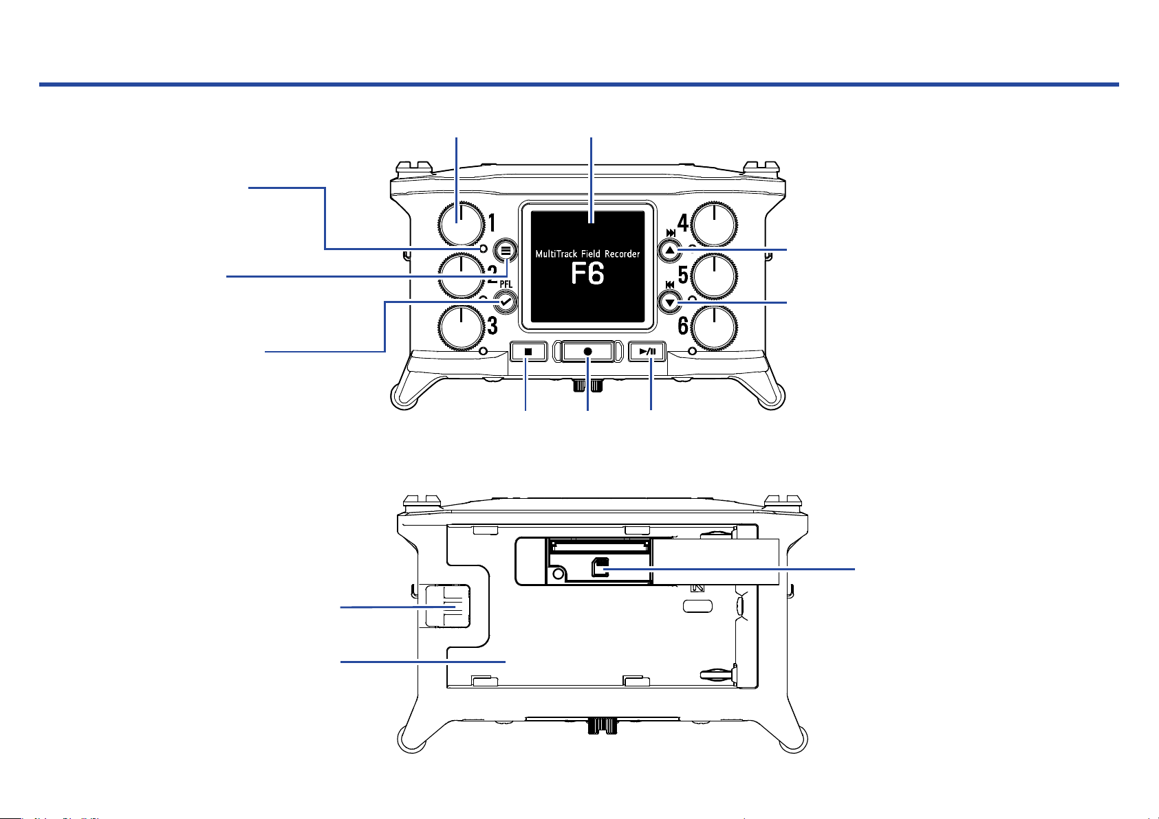
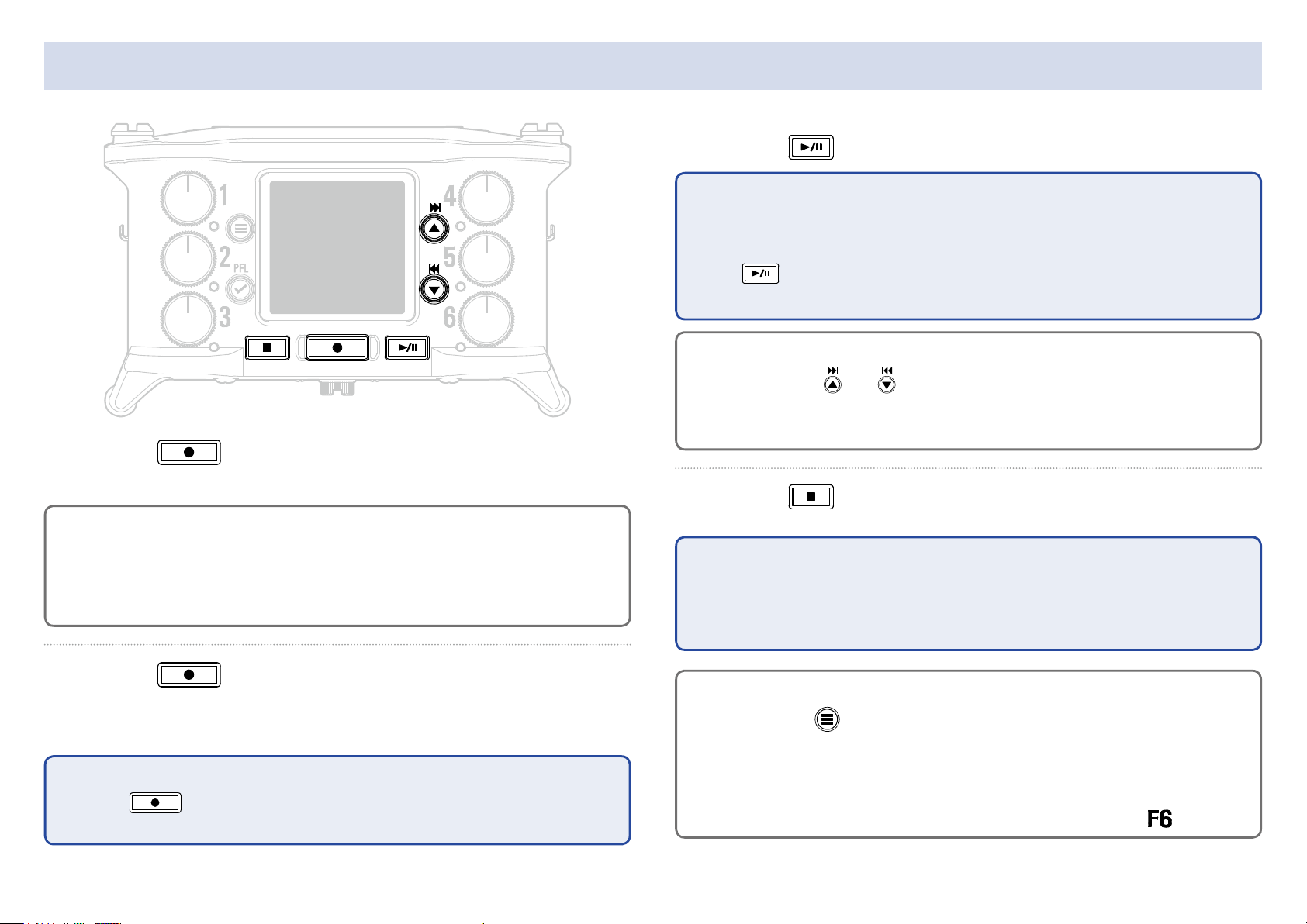
Names of parts
■ Front
Status indicator
Red: Input enabled
Green: Playback track
enabled
Orange: PFL monitoring
Unlit: Input disabled
MENU button
Home Screen: Open Menu Screen
Menu Screen: Return to previous
screen
PFL/ENTER button
Home Screen: Open PFL Screen
Menu Screen: Confirm menu item
■ Back
Track knob Display
STOP
button
REC
button
FF/↑ button
Home Screen: Select playback take
Menu Screen: Select menu item
RWD/↓ button
Home Screen: Select playback take
Menu Screen: Select menu item
PLAY/PAUSE
button
L battery lock button
L battery mount
SD card slot
06
Page 7
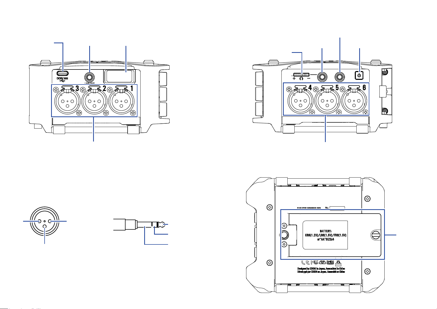
■ Left side
USB port LINE OUT jack Zoom wireless adapter (e.g. BTA-1)
■ Right side
TIMECODE IN/OUT jack
HEADPHONE jack POWER switch
Headphone volume
Inputs 1–3
Inputs 1–6 TIMECODE IN/OUT
3
XLR
12
1:GND
2:HOT
3:COLD
TRS
TIP: Input to F6
(output from external device)
RING: Output from F6
(input to external device)
SLEEVE: GND
Inputs 4–6
Battery
cover
07
Page 8
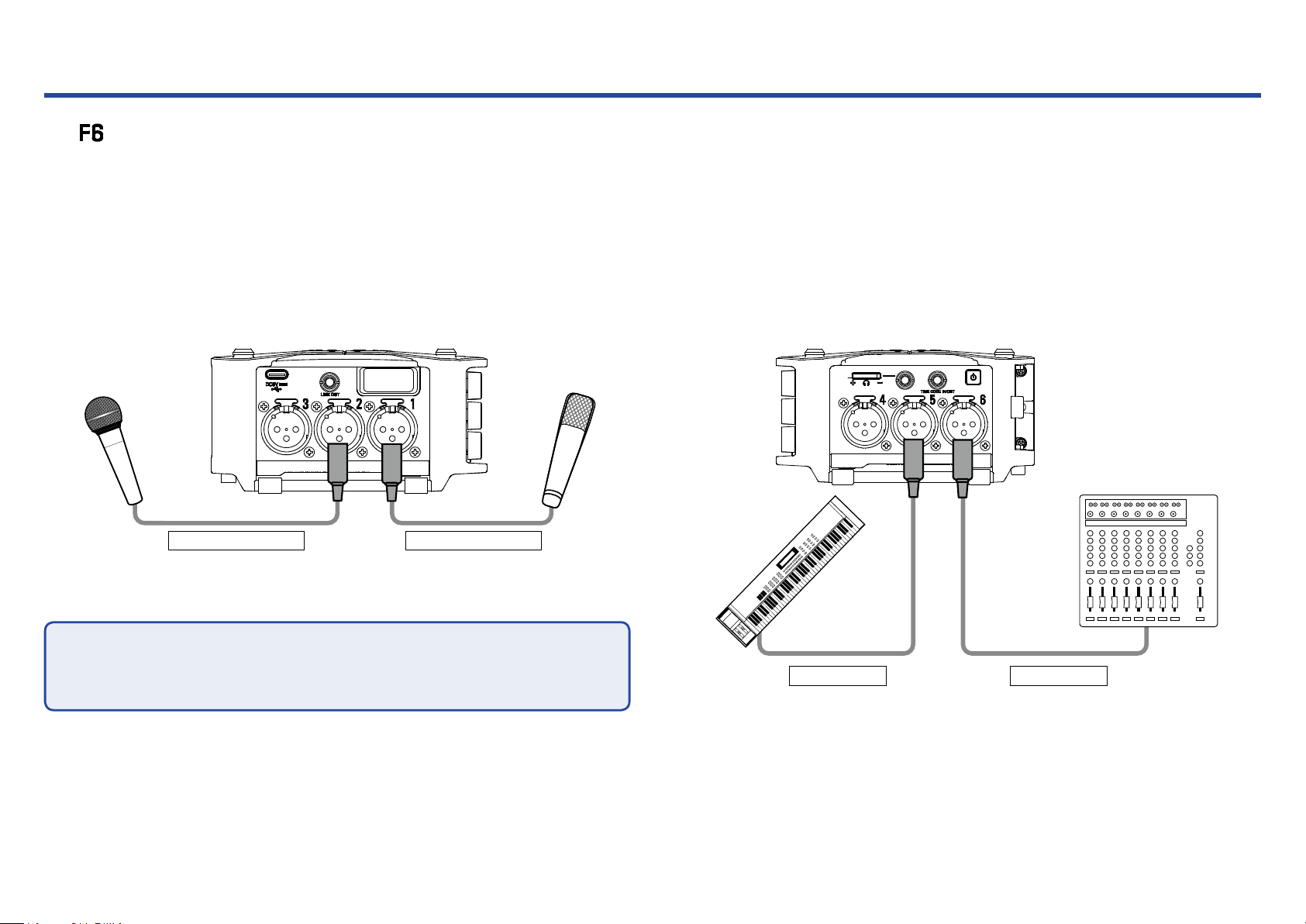
Connecting mics/other devices to Inputs 1–6
The can record 6 individual tracks that correspond to Inputs 1–6 and a stereo mix of these inputs with left and right tracks.
Mics and the outputs of instruments and audiovisual equipment, for example, can be connected to Inputs 1–6 and recorded to tracks 1–6.
Connecting mics
Connect dynamic and condenser mics with XLR plugs to Inputs 1–6.
Phantom power (+24 V/+48 V) can be supplied to condenser mics.
( →P.78)
Connecting line level equipment
Connect XLR cables from keyboards and mixers directly to Inputs 1–6.
Direct input of passive guitars and basses is not supported. Connect
these instruments through a mixer or effects device.
Dynamic mic
(XLR cable)
NOTE
When disconnecting an XLR cable, pull the XLR plug while pushing the connector lock release button.
Condenser mic
(XLR cable)
08
Keyboard
(XLR cable)
Mixer
(XLR cable)
Page 9
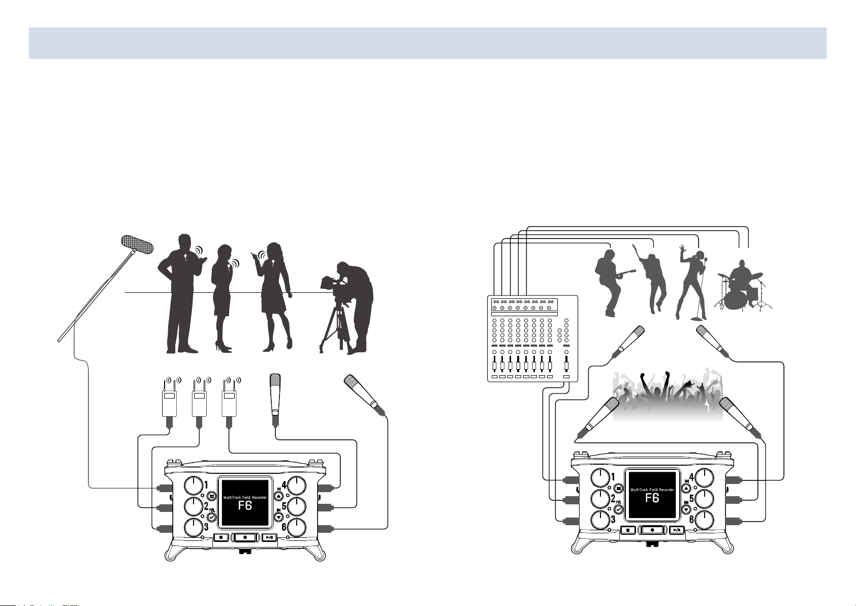
Equipment connection examples
Recording is possible in a variety of situations like these.
While lming
• Input 1: gun mic for main subject sound
• Inputs 2–4: lapel mics for performers
• Inputs 5–6: mics for ambient sound
Gun mic
Pin mics
Pin mics
Ambient
mics
Concert recording
• Inputs 1–2: line inputs for outputs from mixer
• Inputs 3–4: mics for stage performance
• Inputs 5–6: ambient mics for audience sound
Mics
(Stage performance)
PA mixer
Ambient mics
(Audience voices)
1
2
3
4
5
6
1
2
3
4
5
6
09
Page 10
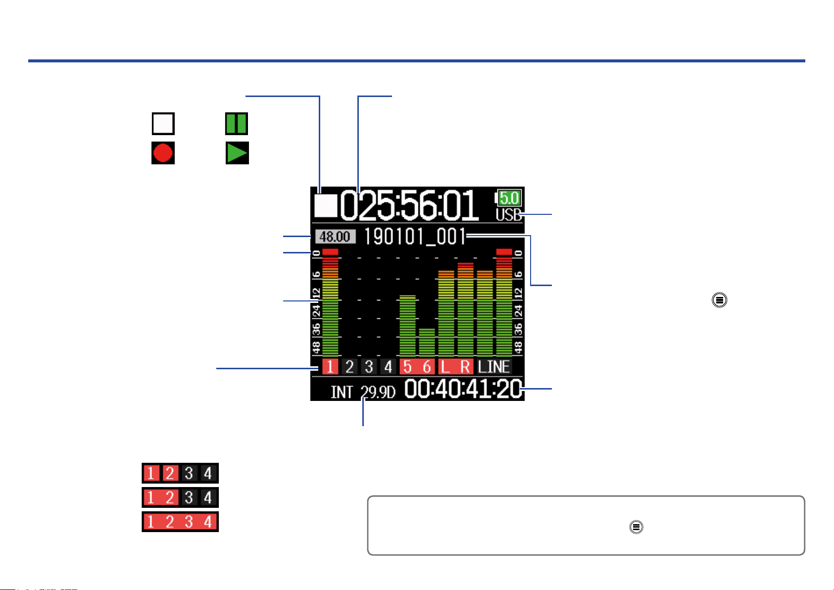
Display overview
■ Home Screen
Status icons
Stopped
Paused
Counter
During recording: Elapsed/remaining recording time
During playback: Elapsed/remaining playback time
Recording
Recording/playback
sample rate
Clip indicator
Level meter
Track number
Red: Input enabled
Green: Playback track enabled
Gray: Input disabled
Input link settings are shown by
connected adjacent track numbers.
Mono
Playing back
Power type and remaining amount
USB: Power supply connected to port
EXT: L battery
AA: AA batteries
Recording/playback take name
When stopped, press and hold
to show the name that will be
given to the next recorded take.
Recording/playback timecode
Frame rate
INT: Internal timecode enabled
EXT: External timecode input enabled
Stereo
Ambisonic
HINT
•
•
When the Home Screen is not open, press and hold
• Some of the screen will appear differently when the recording mode is Float (32 bit).
•
to return to the Home Screen.
10
Page 11
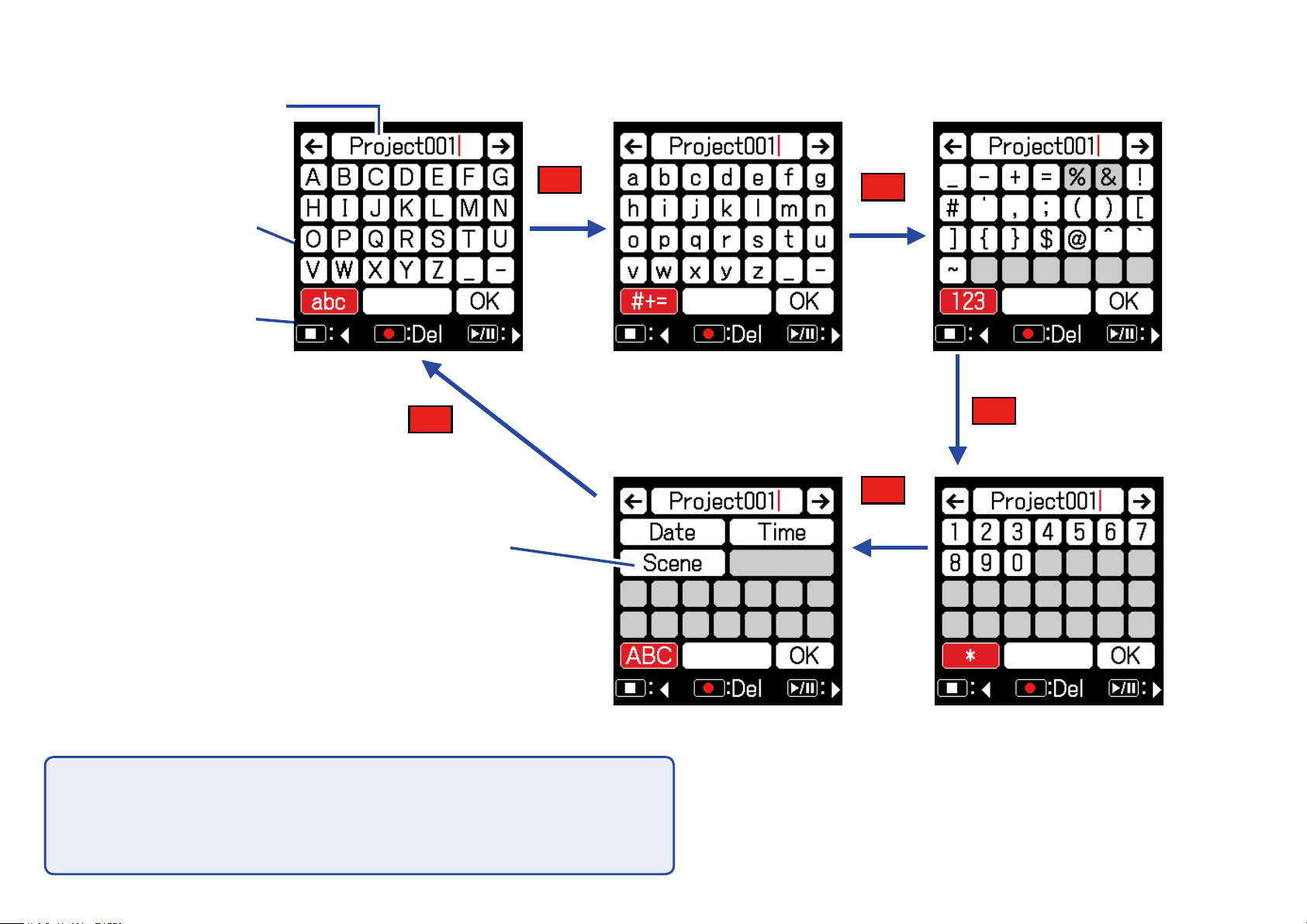
■ Character input screen
Text box
Keyboard
Operation
indicator
Press
input button
*
Automatic
Press
abc
Press
#+=
Press
123
Press
*
NOTE
• The following characters can be used in project names.
•
• (space) ! # $ ' ( ) + , - 0 1 2 3 4 5 6 7 8 9 ; = @ A B C D E F G H I J K L M N O P Q
•
R S T U V W X Y Z [ ] ^ _ ` a b c d e f g h i j k l m n o p q r s t u v w x y z { }
11
Page 12
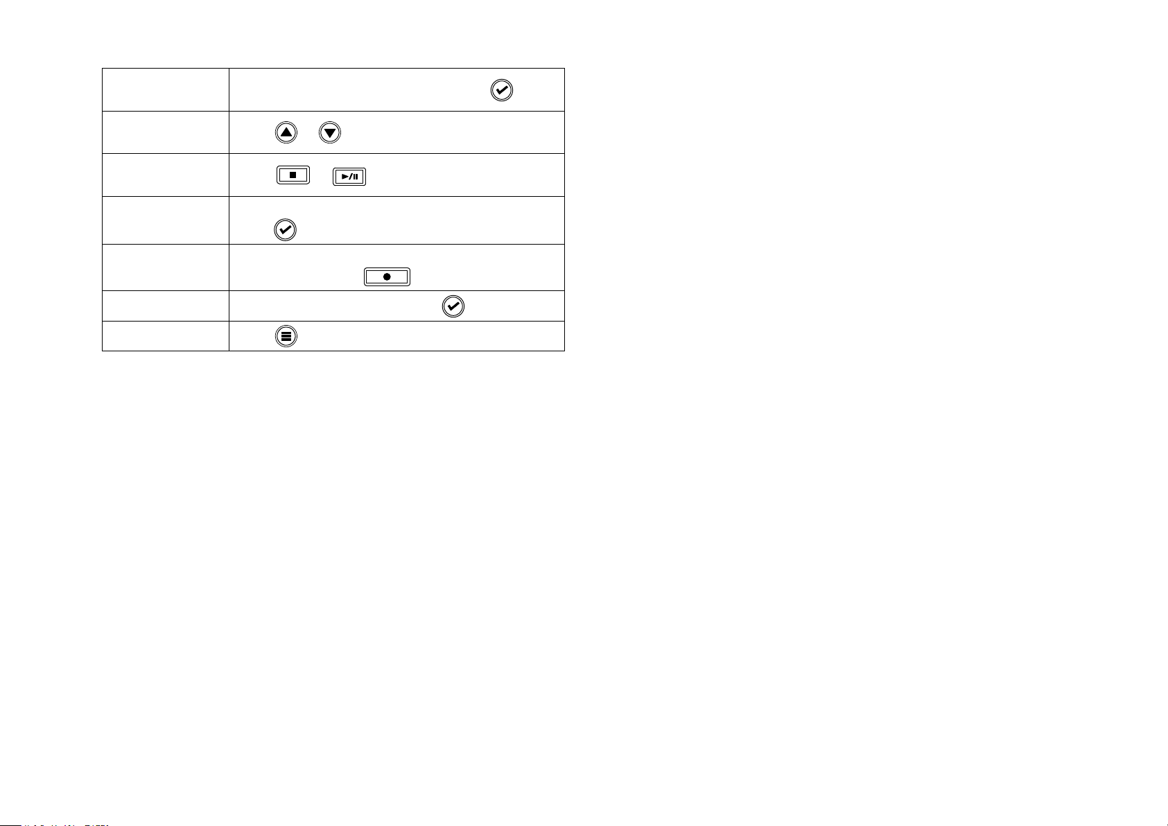
■ Editing operations
Move cursor in
text box
Select characters
(vertical)
Select characters
(horizontal)
Conrm
characters
Delete characters
Use “ ←” and “ →” to move and press
Press
Press
Move the cursor to the character to input, and
press
Move cursor before the character to delete in the
text box, and press
or
or
Complete editing
Cancel editing
Move cursor to "OK" and press
Press
■ Automatic input keys
(Date): This automatically inputs the date. Example: 190210
(Time): This automatically inputs the time. Example: 180950
(Scene): This automatically inputs the current scene name.
12
Page 13
Preparations
Supplying power
Power can be supplied three ways using AA batteries, an L battery or USB.
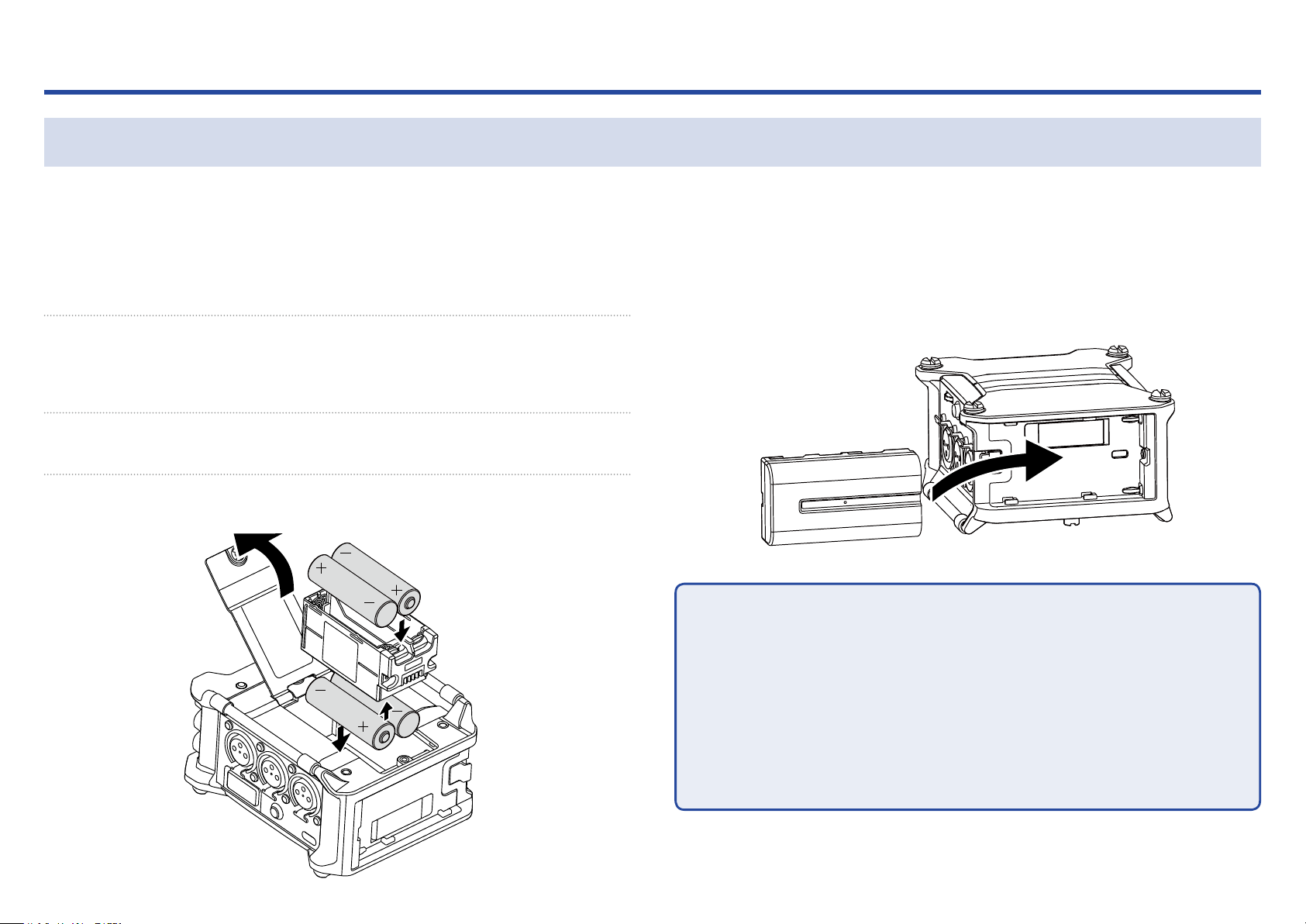
■ Using AA batteries
1. Loosen the screw in the battery cover on the bottom.
2. Open the battery compartment cover on the bottom,
remove the battery case, and insert 4 AA batteries.
3. Put the case into the compartment.
4. Close the battery cover and tighten the screw.
■ Using an L battery
1. Slide the battery in the direction of the arrow while
pressing it toward the recorder.
NOTE
• Be careful because the battery case could become loose unexpectedly if
•
the battery compartment cover screw is not tightened rmly.
• Use only one type of batteries (alkaline, NiMH or lithium) at a time.
•
• After loading AA batteries, set "Power Source" to the correct type of bat-
•
tery. ( →P.20)
• If the remaining battery power indicator becomes red, turn the power off
•
immediately and install new batteries.
13
Page 14
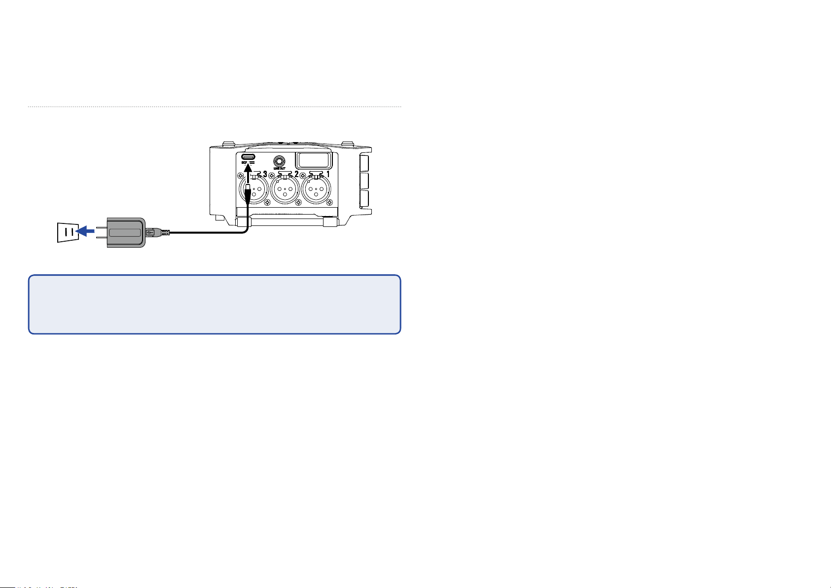
■ Using a USB Type-C cable
1. Connect the cable of the dedicated ZOOM AD-17 AC
adapter to the USB port.
2. Plug the dedicated AC adapter into an outlet.
NOTE
• A 5V mobile battery (commercially-available) can also be connected.
•
• When connected to a computer, power can be supplied by USB.
•
14
Page 15
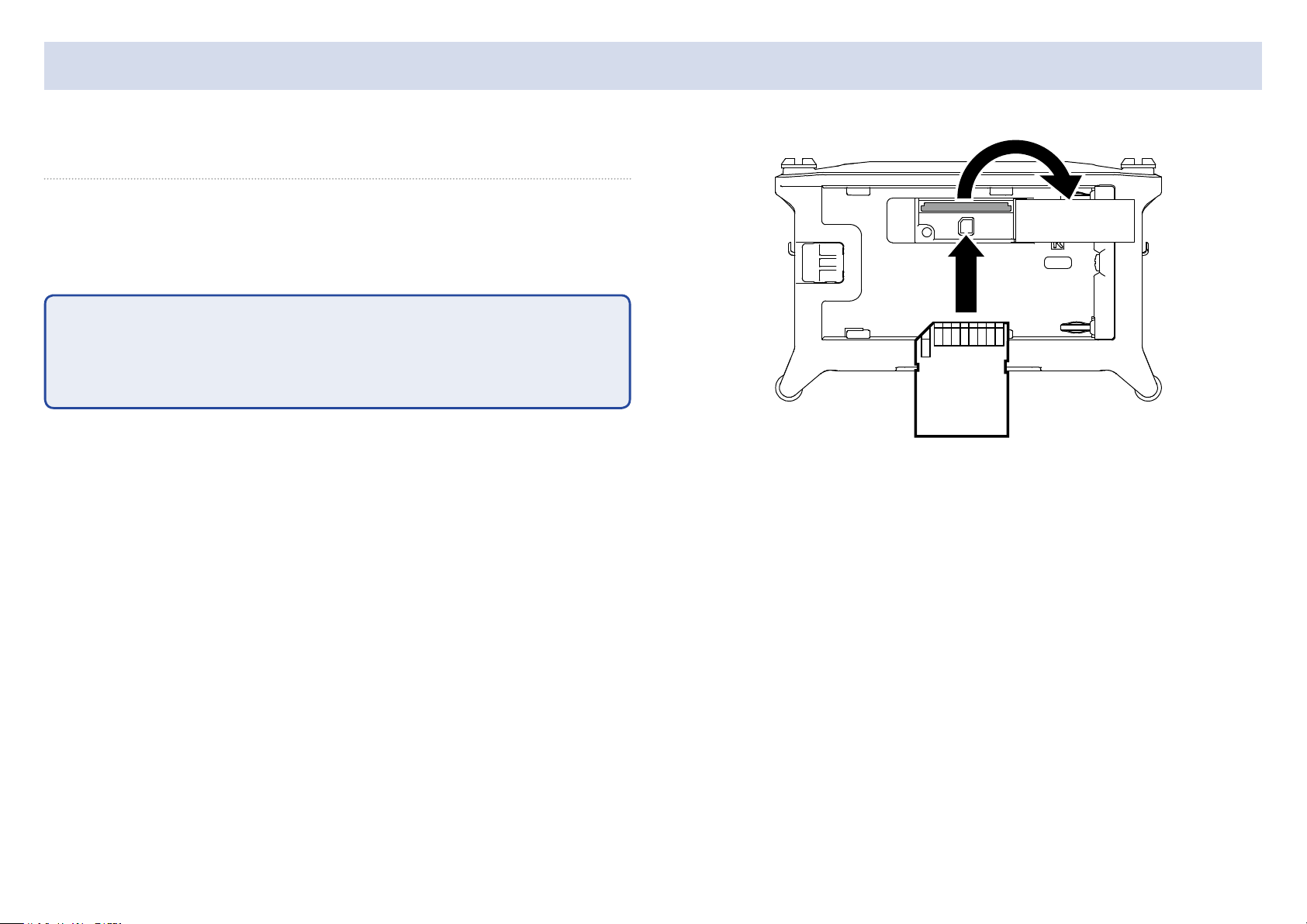
Loading SD cards
1. Open the SD card slot cover, and insert an SD card.
2. To remove the card: push it further into the slot and
then pull it out.
NOTE
Before using SD cards that have just been purchased or that have been formatted on a computer, they must be formatted. To format an SD card, use
Menu > SYSTEM > SD Card > Format.
15
Page 16
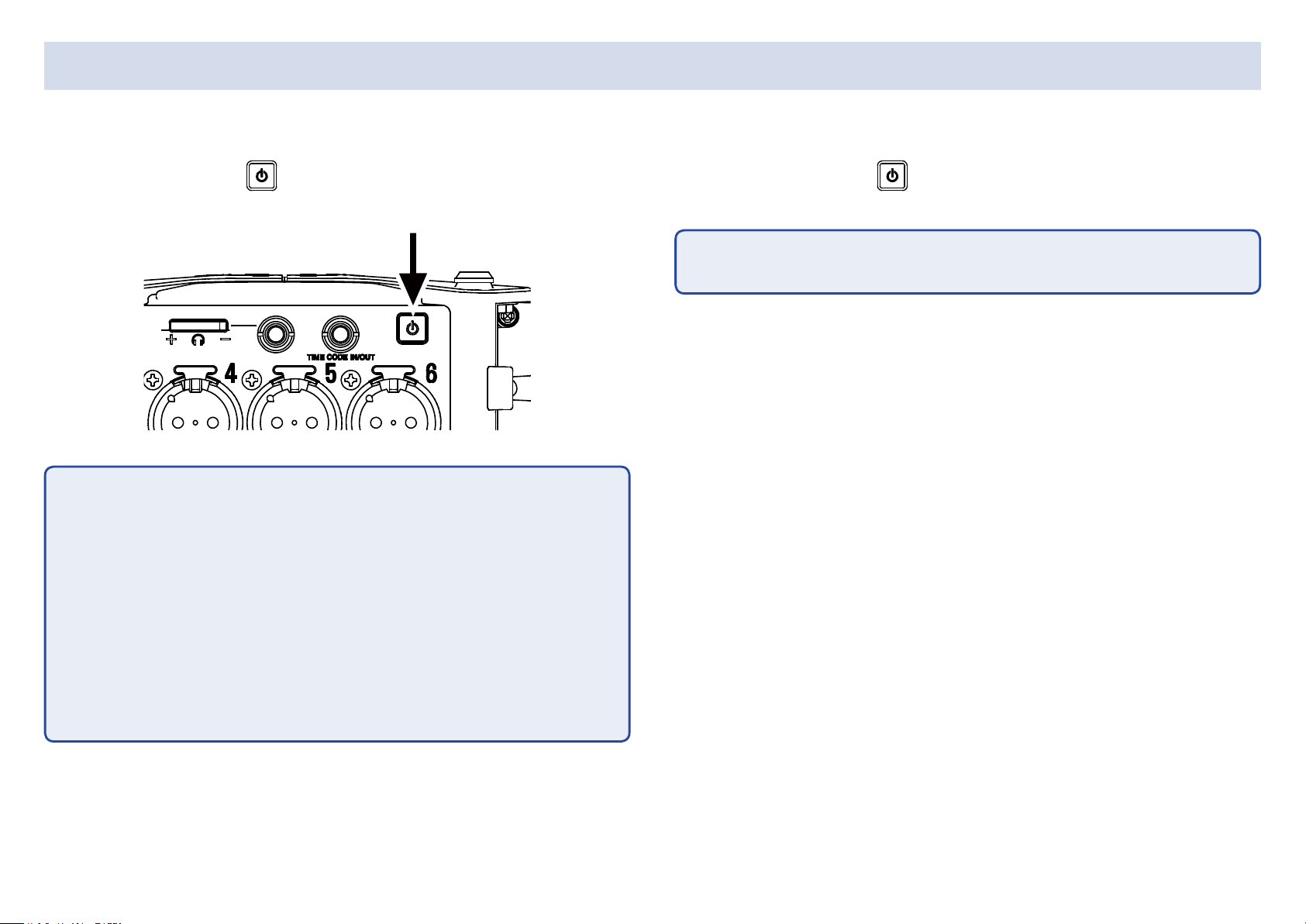
Turning the power on and off
■ Turning the power on
1. Press and hold briey.
The ZOOM logo appears and the power turns on.
NOTE
• The rst time the power is turned on after purchase, the date/time must
•
be set ( →P.18). This setting can also be changed later.
• If “No Card!” appears on the display, conrm that an SD card is inserted
•
properly.
■ Turning the power off
1. Press and hold briey.
NOTE
Keep pressing it until the ZOOM logo appears on the LCD.
• If “Card Protected!” appears on the display, the SD card write-protection is
•
enabled. Slide the lock switch on the SD card to disable write-protection.
• If “Invalid Card!” appears on the display, the card is not formatted cor-
•
rectly. Format the card or use a different card. Formatting SD cards
( →P.175)
16
Page 17
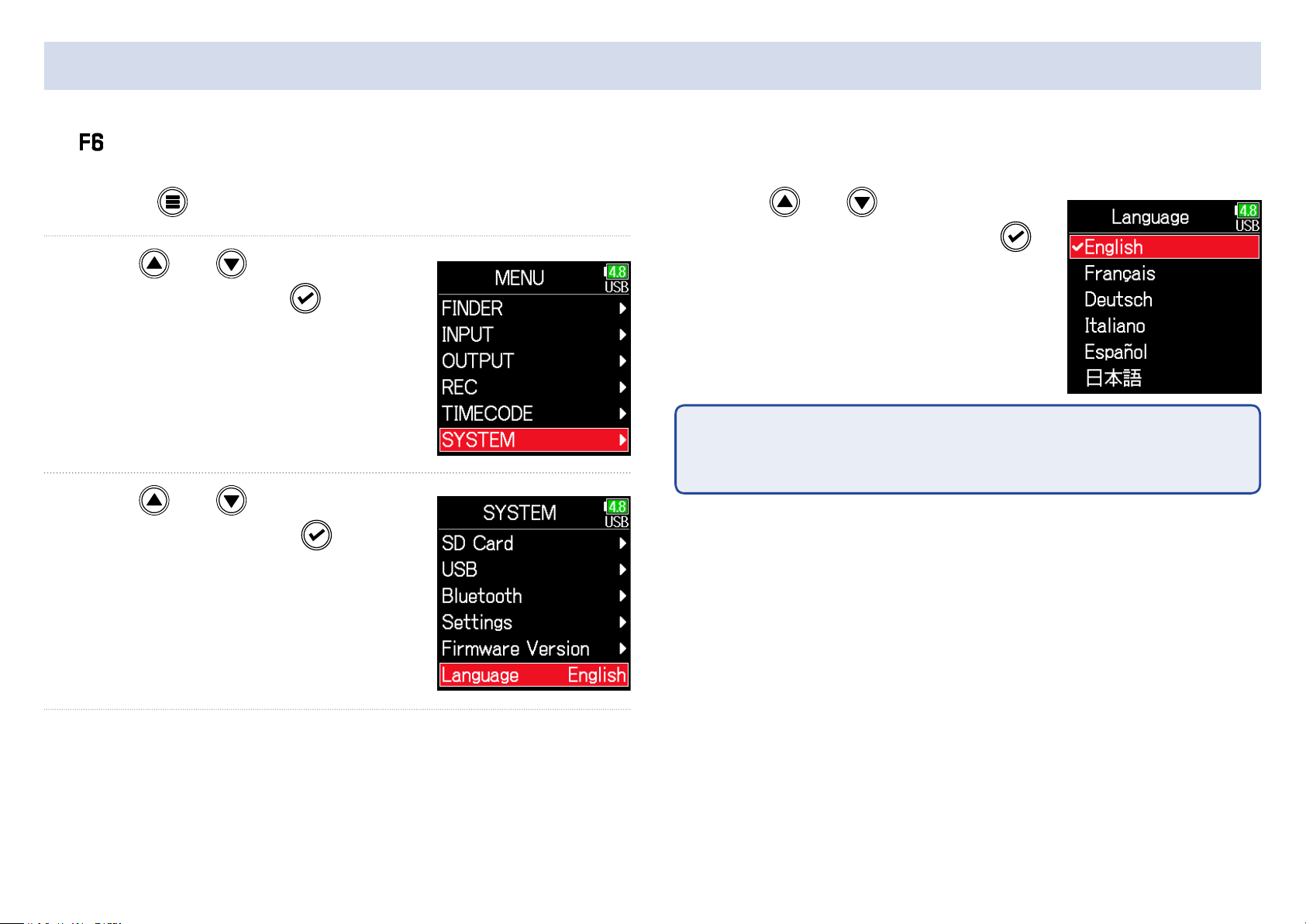
Setting the language
The menu display language can be changed.
1. Press .
2. Use and to select
SYSTEM, and press
.
3. Use and to select
Language, and press
4. Use and to select the
desired language, and press
NOTE
The rst time the power is turned on after purchase, the language must be
set.
.
.
17
Page 18
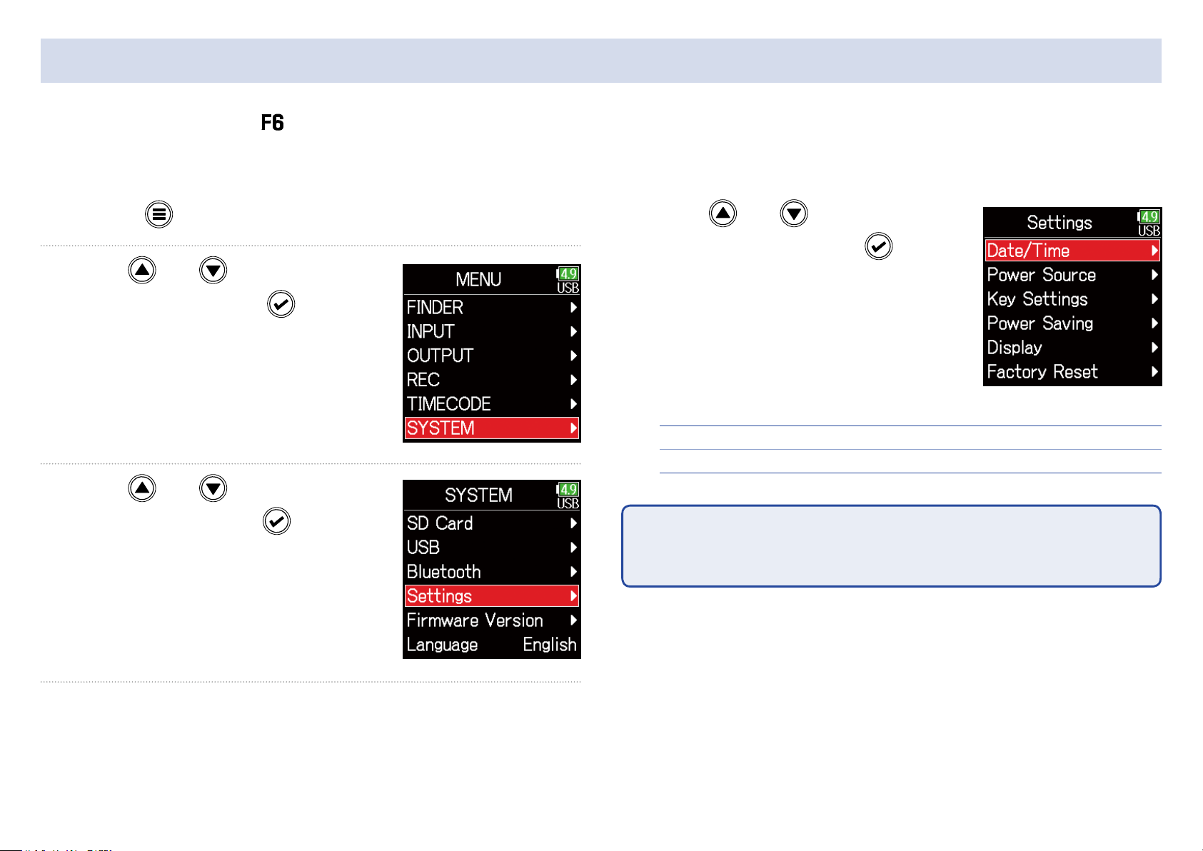
Setting the date and time
The date and time set on the are used when recording les, for example.
The date format (order of year, month and day) can also be set.
1. Press .
2. Use and to select
SYSTEM, and press
.
3. Use and to select
Settings, and press
.
4. Use and to select
Date/Time, and press
▶ Continue to one of the following procedures.
Setting the date and time ……………………………………………………… P.19
Setting the date format ………………………………………………………… P.19
NOTE
The rst time the power is turned on after purchase, the date/time must be
set.
.
18
Page 19
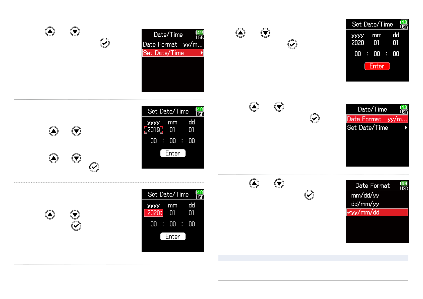
■ Setting the date and time
8. When done setting, use
5. Use and to select Set
Date/Time, and press
.
6. Set the date and time
Move cursor or change value:
Use
Change item value:
Use
the item, and press
and
and to select
.
and to select
Enter, and press
This completes setting the date and
time.
■ Setting the date format
.
5. Use and to select
Date Format, and press
.
7. The item selected to be
changed appears red.
Use
it, and press
and to change
.
6. Use and to select
the format, and press
Setting Explanation
mm/dd/yy Month, day, year order
dd/mm/yy Day, month, year order
yy/mm/dd Year, month, day order
19
.
Page 20
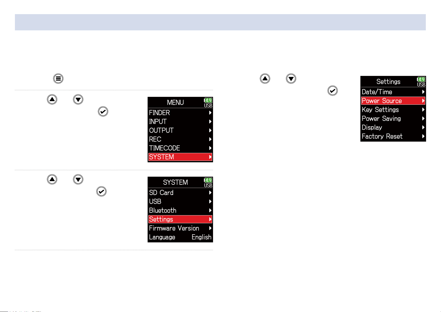
Setting the power supply used
When using AA batteries, set the battery type so that the amount of remaining power can be shown accurately.
The voltage of each power supply and the remaining battery charge can be checked on this menu page.
1. Press .
2. Use and to select
SYSTEM, and press
.
3. Use and to select
Settings, and press
.
4. Use and to select
Power Source, and press
.
20
Page 21
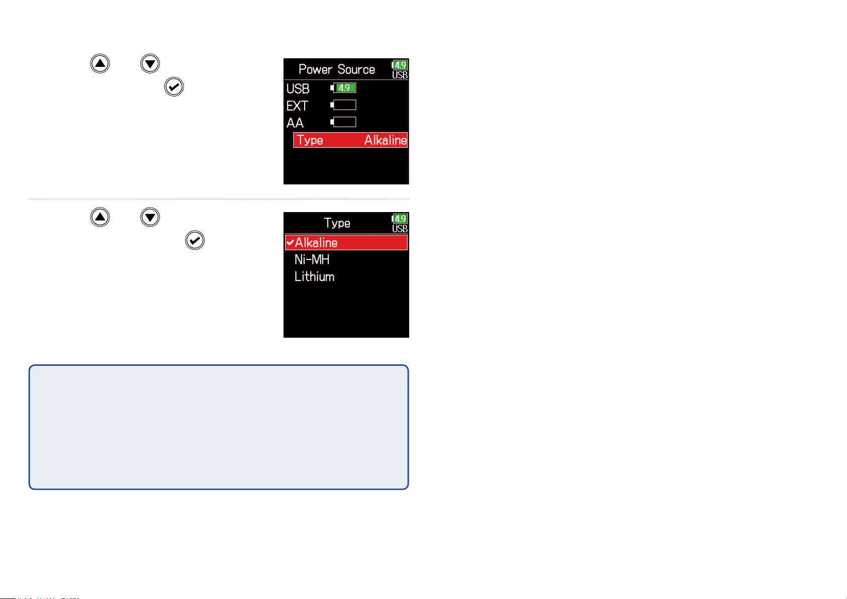
■ Setting the installed AA battery type
5. Use and to select
Type, and press
.
6. Use and to select
the type, and press
NOTE
• When multiple power supplies are connected, they will be used in the fol-
•
lowing order of priority.
1. USB (Power supply connected to USB port)
2. EXT (L battery)
3. AA (Installed AA batteries)
.
• The voltages of each power supply are shown on the display.
•
21
Page 22
Recording
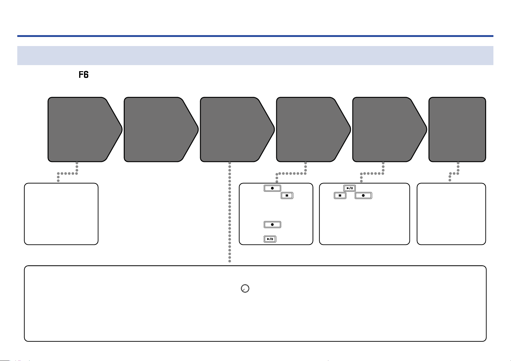
Recording process
Recording with the follows the process shown below.
The data created for each recording occurrence is called a "take".
Connecting
Connect mics, instruments, audiovisual
devices, and other equipment to Inputs 1–6.
( →P.8)
1. Set the recording mode
(bit depth) ( →P.29).
• Select one of the recording
modes: 16/24-bit WAV, 32-bit
Float WAV, simultaneous
16/24-bit WAV and 32-bit WAV,
or MP3.
Turning the
power on
( →P.16)
2. Set the recording le
• Set the recording le format
( →P.23).
• Set the sampling rate
( →P.27).
Preparing to
record
・ Press to start
recording and
stop.
・ Marks (for cueing) can
also be set.
・ Press
recording the next take.
・ Press to pause.
3. Select tracks to record
( →P.48).
• Turn the left until it clicks
to disable the input. Input is
enabled at all other positions.
• This can be set to a stereo
track ( →P.96).
to start
Recording
( →P.26)
・ Press to start playback
to
and
・ Marks (for cueing), for exam-
ple, can also be set.
or to stop.
4. Make various input and
recording settings
• Settings, including metadata ( →P.64), pre-re-
cording ( →P.35), low-cut
lter ( →P.82) and limiter
( →P.84) can be made.
Playing and
checking
( →P.51)
Checking take
information
( →P.64)
・ Check and edit
metadata.
5. Adjust input levels
( →P.25).
• Setting input levels is necessary in some operation modes.
22
Page 23
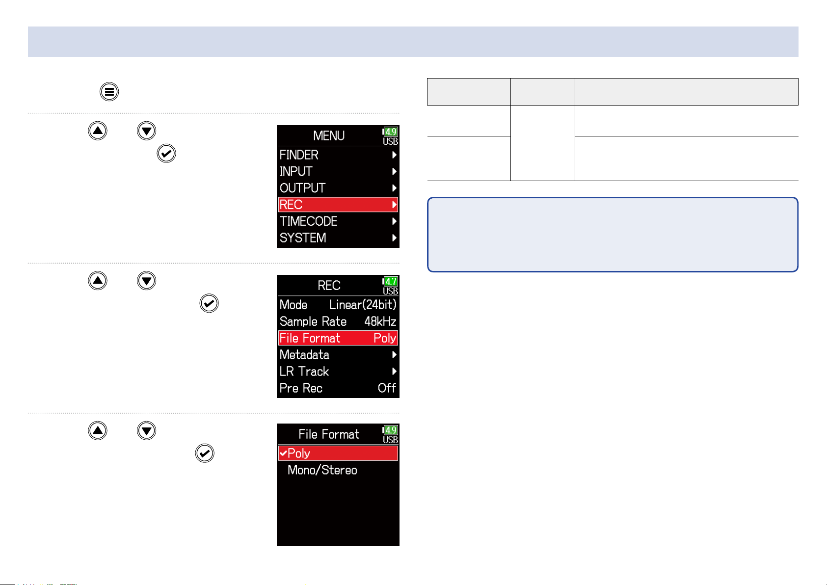
Setting the recording le format
1. Press .
2. Use and to select
REC, and press
.
3. Use and to select
File Format, and press
Setting
Poly
Mono/Stereo
NOTE
• When recording Mono/Stereo, audio les are saved in a folder that is cre-
•
ated. ( →P.40)
• This cannot be set when the mode is set to MP3.
•
Tracks
recorded
Selected
tracks 1-6
Explanation
A single poly le will be created that contains
audio for multiple tracks.
A single mono le is created for each mono
track and a single stereo le is created for
each stereo track.
.
4. Use and to select the
le format, and press
.
23
Page 24
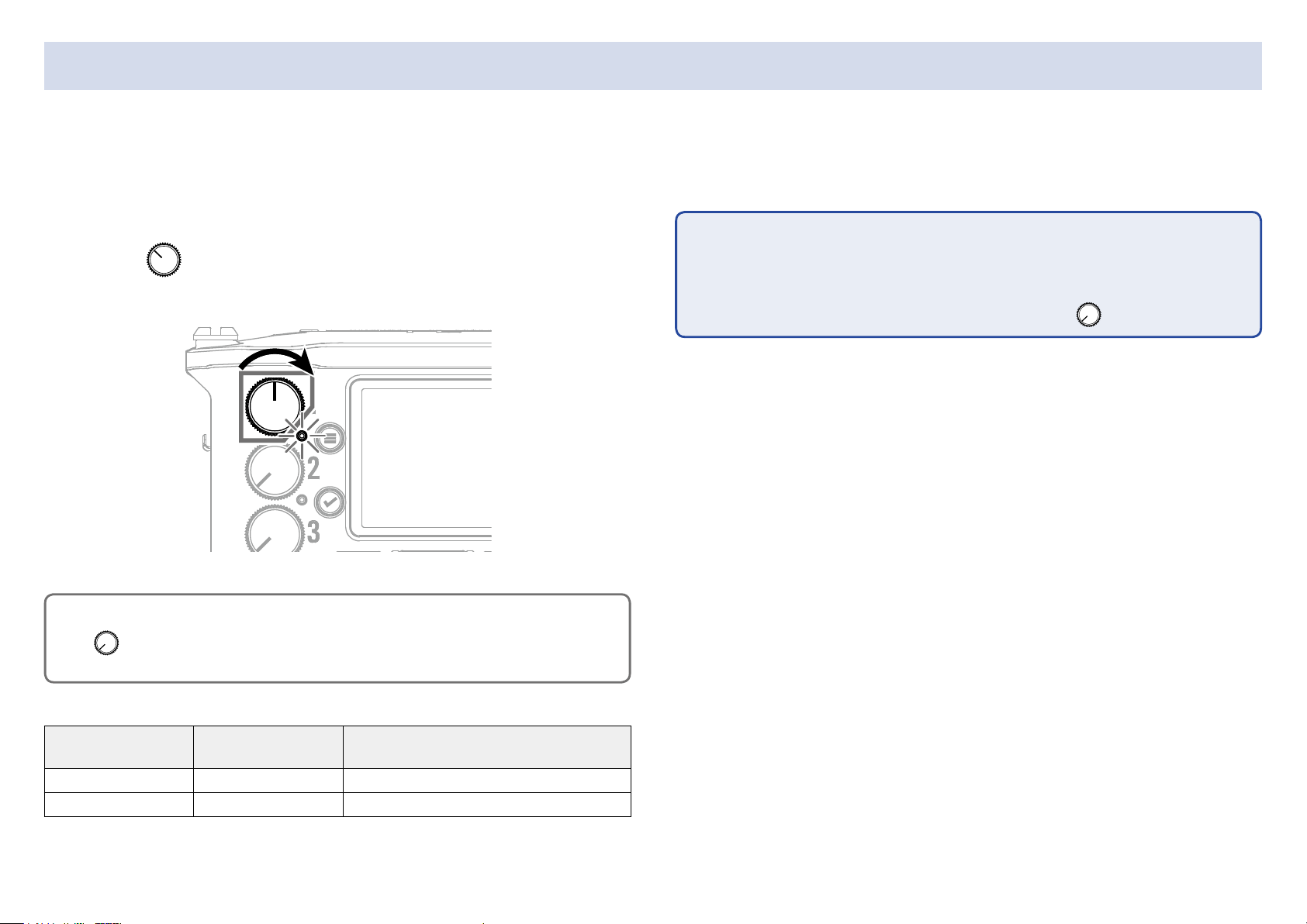
Selecting inputs and adjusting levels
Select which among Inputs 1–6 to use.
Inputs will be recorded on tracks with the same numbers. For example, Input 1 will be recorded on track 1 and Input 2 will be recorded on track 2.
Selecting inputs
1. Turn right for the number of an input to record,
making the track status indicator light.
HINT
Turn left until it clicks to disable the input. Input is enabled at all other
positions.
NOTE
• The signals from the inputs selected this way will also be sent to the L/R
•
tracks.
•
•
The levels sent to the L/R tracks are adjusted with
.
Track indicator
Lit red Red The input is enabled.
Unlit Gray The input is disabled.
Track number
background color
Explanation
24
Page 25
■ Adjusting input levels
5. Use and to select
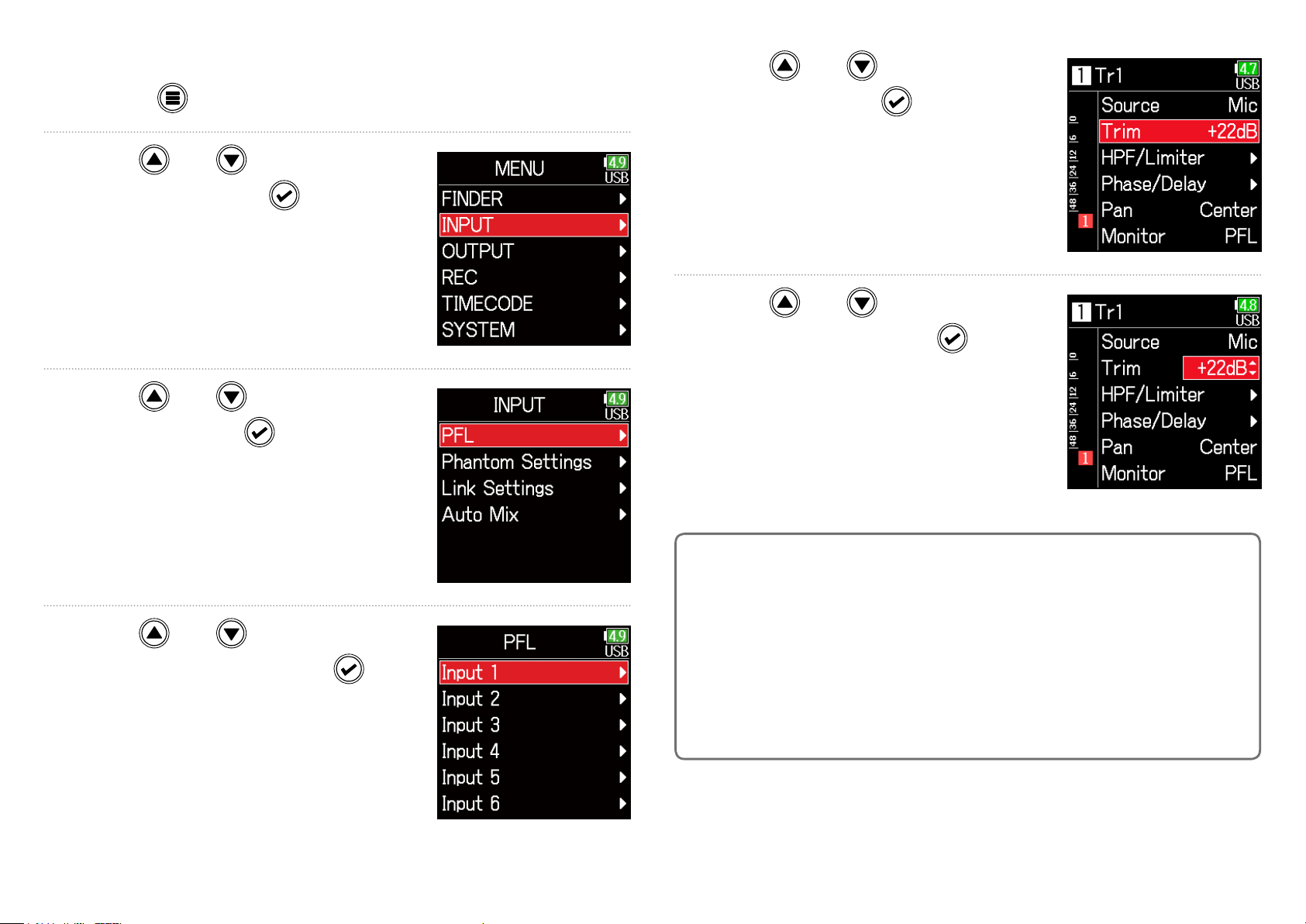
1. Press .
2. Use and to select
INPUT, and press
.
3. Use and to select
PFL, and press
.
Trim, and press
.
6. Use and to adjust the
input level, and press
.
4. Use and to select the
desired track, and press
.
HINT
• This can be set in a range from +12 to +75 dB when the input source is
•
set to Mic, from –8 to +55 dB when set to Line, and from –35 to +30 dB
when set to USB.
• If the sound distorts even after lowering the input level, try changing mic
•
positions and adjusting the output levels of connected devices.
• Using the limiter ( →P.84)
•
• Using the high pass lter ( →P.82)
•
25
Page 26
Recording
3. Press to pause.
NOTE
• Pausing occurs at whole second increments.
•
• When recording is paused, a mark is added at that point.
•
1. Press .
This starts recording.
HINT
If the timecode function is enabled, recording will start from frame 00 (00
or 02 when using drop frame) and the le length will always be a full second value. This makes synchronization easy when editing later.
2. Press to start a new take when recording.
This will end the current take and start a new take while con-
tinuing to record without interruption.
Press
• A maximum of 99 marks can be added to a take.
•
HINT
•
•
During playback,
have been added.
• Marks can be added without pausing. ( →P.167)
•
to resume recording.
and can be pressed to jump to places where marks
4. Press to stop.
NOTE
If the file size exceeds 2GB during recording, a new take will be created
automatically and recording will continue without interruption.
No gap in sound will occur between the two takes when this happens.
HINT
•
•
Press and hold
the next take recorded.
when the Home Screen is open to check the name of
NOTE
Pressing during recording is only possible after recording for at
least a second.
• Files are automatically saved at regular intervals during recording. If
•
the power is interrupted or another problem occurs during recording, an
affected le can be restored to normal by playing it with the
26
.
Page 27
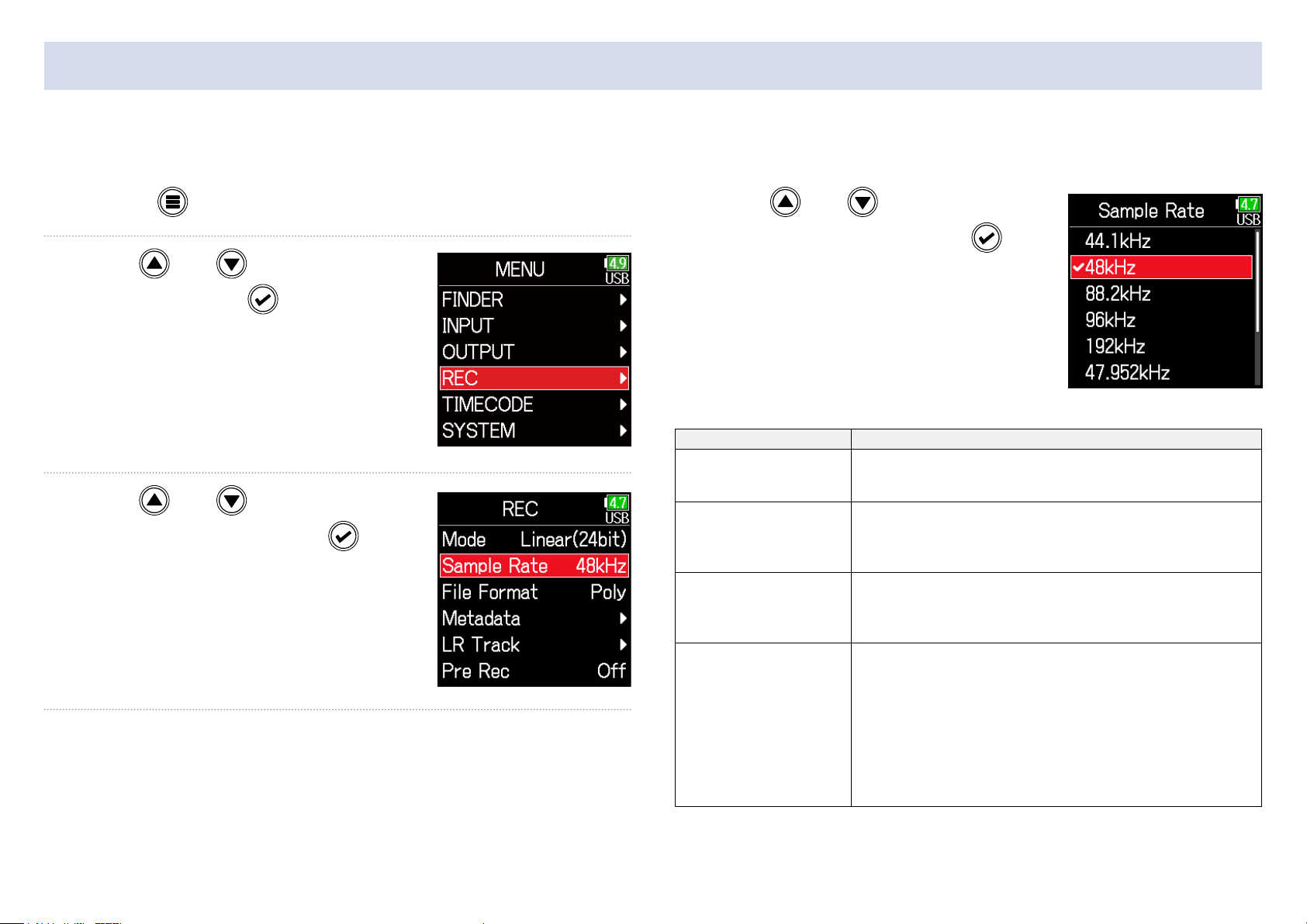
Setting the sampling rate
The sampling rate used to record les can be set.
1. Press .
2. Use and to select
REC, and press
.
3. Use and to select
Sample Rate, and press
4. Use and to select the
sampling rate, and press
Setting Explanation
44.1 kHz, 48 kHz, 88.2
kHz, 96 kHz, 192 kHz
.
47.952 kHz
48.048 kHz
47.952 kHz(F), 48.048
kHz(F)
These are standard sampling rates.
Select this when recording video at 23.976 frames
per second in order to edit later at 24 frames per
second.
Select this when recording video at 24 frames per
second in order to edit later at NTSC 29.97 or 23.98
HD.
These function the same as the two above, but the
sampling rate metadata will be recorded as 48 kHz
for <FILE_SAMPLE_RATE>.
This enables playback and editing with devices and
software that do not support 47.952 kHz and 48.048
kHz WAV les. Playback, however, will occur at the
±0.1% speed at which the le was recorded.
.
27
Page 28

NOTE
• 192 kHz cannot be selected when the recording mode is Float (32bit) and
•
the LR track is on.
• When 192 kHz is selected, Dual (16+32bit) and Dual (24+32bit) cannot be
•
set.
• When the recording mode is MP3, only 44.1 kHz and 48 kHz can be
•
selected.
• When 192 kHz is selected, L/R tracks will not be recorded. Input and out-
•
put delay are also disabled.
• The Limiter cannot be set to On (Advanced) if Auto Mix is On or the Ambi-
•
sonic format is not set to Off.
• AIF with Rec cannot be used when values other than 44.1 kHz or 48 kHz
•
are selected.
28
Page 29
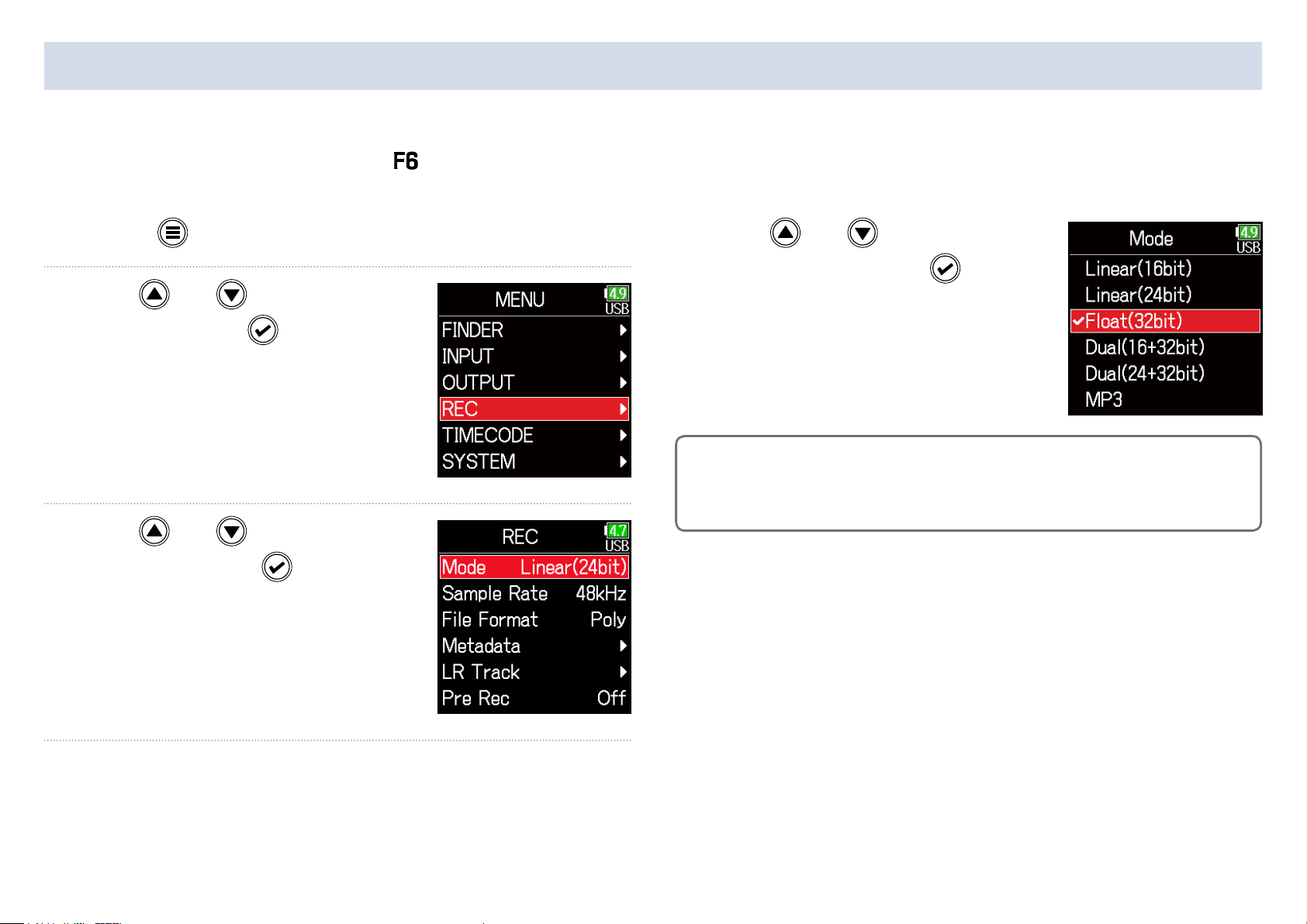
Setting the recording mode (bit depth)
Set the recording mode.
The bit depth of WAV les recorded by the will change according to the mode setting.
1. Press .
2. Use and to select
REC, and press
.
3. Use and to select
Mode, and press
.
4. Use and to select
the mode, and press
HINT
The setting options are Linear (16bit), Linear (24bit), Float (32bit), Dual
(16+32bit), Dual (24+32bit) and MP3.
.
29
Page 30
Mode setting Mode name Explanation
Linear (16bit)
Linear
Linear (24bit)
Float (32bit) Float
Dual (16 + 32bit)
Dual
Dual (24 + 32bit)
These modes record ordinary 16/24-
bit WAV les.
Adjust input (trim) levels so that
the clip indicators do not light when
recording. The level meters show input
levels after adjustments.
This mode records 32-bit oat WAV
les. Adjusting input levels is unneces-
sary. As long as maximum input levels
are not exceeded, both quiet and loud
sounds can be recorded with high
quality.
The level meters show levels after
adjustments by
These modes simultaneously record
ordinary 16/24-bit WAV les and 32-bit
oat WAV les.
Adjust input (trim) levels so that
the clip indicators do not light when
recording.
Even if clipping occurs in 16/24bit
WAV le data during recording, data
at a suitable level without clipping can
be obtained by editing the 32bit Float
WAV les during post-production.
knobs.
MP3 MP3
This mode records MP3 les.
Trim setting is necessary in this mode.
30
Page 31

Setting MP3 le bit rate (MP3)
The bit rate used for recording MP3 les can be set.
1. Press .
2. Use and to select
REC, and press
.
3. Use and to select
Mode, and press
.
4. Use and to select
MP3, and press
.
5. Press to return to
the REC screen.
6. Conrm that the Mode is set to
MP3. Then, use
select Bit Rate, and press
31
and to
.
Page 32

7. Use and to select
the bit rate, and press
HINT
This can be set to 128 kbps, 192 kbps or 320 kbps.
.
32
Page 33

Setting the LR Track
■ Enabling the LR track
1. Press .
2. Use and to select
REC, and press
.
3. Use and to select
LR Track, and press
.
4. Use and to select
On/Off, and press
.
5. Use and to select
On, and press
.
• NOTE
•
• Off: This disables the LR Track.
•
• On: This enables the LR Track. All selected tracks and the LR Track will be
•
recorded.
• On (LR only): This enables the LR Track. Only the LR Track will be
•
recorded.
• On cannot be selected if the simple rate is 192 kHz or the recording mode
•
is Float (32bit).
33
Page 34

■ Adjusting the L/R track volume
1. Press .
2. Use and to select
5. Use and to select
LR Fader, and press
.
REC, and press
.
3. Use and to select
LR Track, and press
.
4. Use and to select
6. Use and to change
the LR fader value, adjust-
ing the LR track volume.
NOTE
Pressing + when the Home Screen is open will also open the LR/
Line Out setting screen.
LR Fader, and press
.
34
Page 35

Capturing audio before recording starts
The input signal is always buffered for a set amount of time, so it can be captured for up to 6 seconds before is pushed (pre-recording). This
is useful when is pressed late, for example.
1. Press .
2. Use and to select
REC, and press
.
3. Use and to select
Pre Rec, and press
.
4. Use and to select
.
WAV
MP3
On, and press
Sample Rate Maximum pre-recording time
44.1 kHz 6 seconds
48 kHz 6 seconds
88.2 kHz 3 seconds
96 kHz 3 seconds
192 kHz 1 second
47.952 kHz 6 seconds
47.952 (F) kHz 6 seconds
48.048 kHz 6 seconds
48.048 (F) kHz 6 seconds
44.1 kHz 6 seconds
48 kHz 6 seconds
NOTE
Pre-recording will be disabled if MENU > TIMECODE > Mode ( →P.124) is
set to Int Record Run, Ext or Ext Auto Rec.
35
Page 36

Setting the recording time display
During recording, either the elapsed recording time or the remaining possible recording time can be shown.
1. Press .
2. Use and to select
SYSTEM, and press
.
3. Use and to select
Settings, and press
.
4. Use and to select
Display, and press
.
5. Use and to select
Time Display, and press
.
36
Page 37

6. Use and to select
Recording, and press
NOTE
When recording for a long time, if the le size
.
exceeds 2 GB, recording will continue in a new
le and the recording time will reset. This can
be changed, however, so that it is not reset and
the total recording time is shown.
Set Rec Time Reset on the Time Display screen
to On/Off to set whether or not recording time
resets when a new le is created.
7. Use and to select the
time to show, and press
.
Off: When recording, even if the file size
reaches 2GB, the counter shown on the
Home Screen will not reset.
On (reset): When recording, if the file size
reaches 2GB, the counter shown on the
Home Screen will be reset to 000:00:00.
37
Page 38

Setting the playback time display
During playback, either the elapsed playback time or the remaining playback time can be shown.
1. Press .
2. Use and to select
SYSTEM, and press
.
3. Use and to select
Settings, and press
.
4. Use and to select
Display, and press
.
5. Use and to select
Time Display, and press
.
6. Use and to select
Playing, and press
38
.
Page 39

7. Use and to select the
time to show, and press
.
39
Page 40

Folder and le structure
When recording with the , folders and les are created on the SD card in the following manner.
folders and les are used to manage scenes and takes as a rule.
Folder and le structure
The folder and le structure differs according to the recording le format. In addition, the names of folders and les depend on how scenes
are named.
Root
Recording order
190101_001.WAV
Scene 190101
(1st take)
WAV format
polyphonic file
→
190101_002.MP3
Scene 190101
(2nd take)
MP3 format
stereo file
190101_003.TAKE
190101_003_Tr1.WAV
190101_003_Tr2.WAV
190101_003_Tr3.WAV
Scene 1
(Folder created by user)
Scene001
Scene001_001.WAV Scene001_002.MP3
Scene001
(1st take)
WAV format
polyphonic file
Scene001
(2nd take)
MP3 format
stereo file
NOTE
• Setting the recording le format ( →P.23)
•
• Setting how scenes are named (mode) ( →P.45)
•
HINT
Take: This is a unit of data created for a single recording.
Scene: This is a unit containing multiple files and takes that comprise a
single scene.
Scene 2
(Folder created by user)
Scene002
Scene001_003.TAKE
Scene001_003_Tr1.WAV
Scene001_003_Tr2.WAV
Scene002_001.WAV Scene002_002.MP3
Scene002
(1st take)
WAV format
polyphonic file
Scene002
(2nd take)
MP3 format
stereo file
Scene002_003.TAKE
Scene002_003_Tr1.WAV
Scene002_003_Tr2.WAV
190101_003_Tr4.WAV
190101_003_Tr5_6.WAV
190101_003_TL_R.WAV
Scene 190101 (3rd take)
WAV format
Mono files (tracks 1–4)
Stereo file (tracks 5, 6)
Stereo file (tracks L, R)
Recording when scene naming is set to “Date”
Scene001_003_Tr3.WAV
Scene001_003_Tr4.WAV
Scene001_003_Tr5_6.WAV
Scene001_003_TL_R.WAV
Scene001 (3rd take)
WAV format
Mono files (tracks 1–4)
Stereo file (tracks 5, 6)
Stereo file (tracks L, R)
40
Recording when scene naming is set to “Current Folder”
Scene002_003_Tr3.WAV
Scene002_003_Tr4.WAV
Scene002_003_Tr5_6.WAV
Scene002_003_TL_R.WAV
Scene00 (3rd take)
WAV format
Mono files (tracks 1–4)
Stereo file (tracks 5, 6)
Stereo file (tracks L, R)
Page 41

■ Take names
■ Audio le names
Scene001-001
Structure Explanation
Scene name: Select none, the folder
name, the date or a name input by the
Take number
(001–999)
Scene number
(1-9999)
Scene
Name
user ( →P.45).
Scene number: Press
increase the number by one.
Take number: This number increases
by 1 with each recording made with
the same scene name and scene
number.
+ to
File names given by the differ according to polyphonic, mono and
stereo file formats. Track numbers and other data are added to file
names.
File names
File names are given according in the following formats.
Type Structure Explanation
This is a le created by
polyphonic recording.
Audio for multiple tracks
is recorded to a single
le.
This is a le created by
monophonic recording.
This is a le created by
stereophonic recording.
This is a 32bit Float
WAV le created when
in Dual recording mode.
This is a le created
automatically when the
le size exceeded 2 GB
during recording. The
long recording le number increases one each
time the le changes.
Poly le
Mono le
Stereo le
Float le
in Dual
mode
Long
recording
le
Scene001-001.wav
Take name
Scene001-001_Tr1.wav
Track number
Take name
Scene001-001_Tr1_2.wav
Track number
Take name
Scene001_001_32FP.wav
Float le characters
Scene001_001_0002.wav
Long recording le number
HINT
When recording with a Mono/Stereo setting, the audio les are saved in a
take folder that is created.
41
Page 42

Move the previously recorded take to the FALSE TAKE folder.
If the just recorded take was a failure, a shortcut can be used to move the recording to the FALSE TAKE folder.
1. Open the Home Screen.
2. While pressing , press .
HINT
• Moving a take to the FALSE TAKE folder reduces the take number by one.
•
• Even during recording, the previously recorded take can be moved to the
•
FALSE TAKE folder.
3. Use and to select
Execute, and press
.
42
Page 43

Recorded take settings
Changing the note for the next take recorded
Characters can be input, for example, as a note to use as metadata in les.
1. Press .
2. Use and to select
REC, and press
.
3. Use and to select
Metadata, and press
■ Editing notes
4. Use and to select
Note, and press
.
5. Use and to select
Edit, and press
.
.
▶ Continue to one of the following procedures.
Editing notes …………………………………………………………………………… P.43
Selecting notes from the history list …………………………………… P.44
43
Page 44

6. Edit the note.
■ Selecting notes from the history list
See "Character input screen"
( →P.11) for how to input
characters.
NOTE
This note is written to the <NOTE> metadata.
5. Use and to select
History, and press
.
6. Use and to select
the desired history
item, and press
.
NOTE
The history list will be erased if the Factory Reset function is used.
44
Page 45

Setting and managing recorded scene names
The way scenes are named (name mode) can be set.
1. Press .
2. Use and to select
REC, and press
.
3. Use and to select
Metadata, and press
Setting how scenes are named (mode)
4. Use and to select
Scene Name, and press
.
5. Use and to select
Mode, and press
.
.
▶ Continue to one of the following procedures.
Setting how scenes are named (mode) ……………………………… P.45
Changing scene names ………………………………………………………… P.46
Selecting a scene name from the history list …………………… P.47
45
Page 46

Setting Explanation
The name of the currently selected folder is used as the scene
name.
+
Current
Folder
advancing the scene number by 1, the corresponding folder will
be used as the recording destination. If that folder does not
already exist, it will be created.
Example: FOLDER001-001.wav
The date is used as the scene name.
can be used to advance the scene number by 1. After
■ Changing scene names
If Scene Name Mode is set to User Name, set the scene name used like
this.
4. Use and to select
User Name, and press
.
Date
User Name
+
cannot be used to advance the scene number by 1.
Example: 20190101-001.wav
A scene name input by the user is used.
+
can be used to advance the scene number by 1.
Example: MYSCENE001-001.wav
5. Use and to select
Edit, and press
.
6. Edit the scene name.
See "Character input screen"
( →P.11) for how to input
46
characters.
Page 47

NOTE
• The scene name is written to the <SCENE> metadata.
•
• Spaces and @ marks cannot be input at name beginnings.
•
■ Selecting a scene name from the history list
4. Use and to select
6. Use and to select
the desired history
item, and press
.
User Name, and press
5. Use and to select
History, and press
.
.
NOTE
The history list will be erased if the Factory Reset function is used.
47
Page 48

Changing the track name of the next take recorded (Track Name)
The track name set with the following procedure will be given to the next recorded track.
1. Press .
2. Use and to select
REC, and press
.
3. Use and to select
Metadata, and press
4. Use and to select
Track Name, and press
.
5. Use and to select
a track, and press
.
▶ Continue to one of the following procedures.
.
48
Editing the track name …………………………………………………………… P.49
Selecting a track name from the history list ………………………P.49
Page 49

■ Editing the track name.
■ Selecting a track name from the history list
6. Use and to select
Edit, and press
.
7. Edit the track name.
See "Character input screen"
( →P.11) for how to input
characters.
6. Use and to select
History, and press
.
7. Use and to select
the desired history
item, and press
.
NOTE
The track name is written to the <TRACK> <NAME> metadata.
NOTE
The history list will be erased if the Factory Reset function is used.
49
Page 50

Changing the number of the next take recorded
The number given to the next recorded take can be changed when the Home Screen is open.
1. While pressing , press .
2. Use or to increase
or decrease the take num-
ber, and press
NOTE
This function cannot be used during recording and playback or when the
Scene Name Mode is set to Date. How scenes are named can be changed
with the following menu item.
MENU > Metadata > Scene Name > Mode
.
50
Page 51

Playback
Playing recordings
HINT
•
•
The longer / is pressed and held, the faster the speed of searching
backward/forward.
• An "Invalid Take!" message will appear if the selected take is not valid.
•
• A "No Take!" message will appear if no playable take exists.
•
1. Press .
■ Playback operations
Select take/Jump to mark: Press /
Search backward/forward: Press and hold /
Pause/resume playback: Press
NOTE
Track backgrounds will appear black.
•
•
During playback, press
(→P.167)
to add marks that can be used for skipping.
2. Press to return to the Home Screen.
51
Page 52

Mixing takes
The volume and panning of each track during playback can be changed.
■ Setting faders
1. Touch on the Home
Screen ( →P.10).
2. Turn to adjust the
input signal level.
■ Setting the panning
1. Press .
2. Use and to select
INPUT, and press
.
3. Use and to select
PFL, and press
.
NOTE
Turn left until it clicks to mute the input.
52
Page 53

5. Use and to select the
desired track, and press
.
6. Use and to select
Pan, and press
.
Parameter Setting range Explanation
Fader
(in Float mode)
Fader
(in Linear mode)
Pan L100 – Center – R100
NOTE
• Settings are saved separately for each take and are used during playback.
•
• Mix settings are not saved with the take when the recorded le format is
•
MP3.
Mute, −48.0 – +24.0 dB
Adjusts the input signal level.
Mute, −60.0 – +60.0 dB
Adjusts the stereo balance of
the sound.
7. Adjust the panning.
53
Page 54

Monitoring the playback signals of specic tracks during playback
The playback signals of specic tracks can be monitored using SOLO mode.
1. Open the Home Screen.
2. Press to start playback.
4. Use and to select
INPUT, and press
NOTE
SOLO mode can only be used with tracks that can be played back (indicators lit green).
.
5. Use and to select
PFL, and press
.
3. Press during playback.
54
Page 55

6. Use and to select the
track to monitor, and press
.
55
Page 56

Changing the repeat playback setting
The repeat setting used during playback can be changed.
1. Press .
2. Use and to select
PLAY, and press
.
3. Use and to select
Repeat, and press
.
4. Use and to select the
repeat mode, and press
Setting Explanation
Play One
(single playback)
Play All
(all playback)
Repeat One
(single repeat playback)
Repeat All
(all repeat playback)
Only the selected take will be played.
Takes will be played back continuously from the
selected one until the last one.
The selected take will be played repeatedly.
All takes in the selected folder will be played
repeatedly.
.
56
Page 57

Take and folder operations
Working with takes and folders
The Finder allows the viewing of the contents of SD cards, takes and folders and the creation of project/scene folders. It also allows the setting and
deletion of recording/playback folders along with viewing their information, for example.
1. Press .
■ Editing operations
Cursor: Press /
2. Use and to select
FINDER, and press
.
3. Use and to select the
SD card, and press
.
Move down a level (next): Press
Move up a level (previous): Press
Show Option screen: Press and hold
NOTE
•
•
When the cursor is on a take, pressing
, and can also be used.
• A check mark appears on the playback take and recording/playback
•
folder.
▶ Continue to one of the following procedures.
Creating folders ……………………………………………………………………… P.58
Selecting the take recording/playback folder ……………………P.58
Checking take marks and using them for playback …………P.59
Changing folder and take names ………………………………………… P.59
Deleting folders and takes …………………………………………………… P.60
Emptying the TRASH/FALSE TAKE folders …………………………P.61
will play the selected take.
57
Page 58

■ Creating folders
■ Selecting the take recording/playback folder
Folders can be created inside the currently selected SD card/folder.
5. Use and to select
New Folder, and press
.
6. Edit the folder name.
See "Character input screen"
( →P.11) for how to input
characters.
Use this procedure to select the folder that contains the take to be
played back or the folder to use for recording takes and return to the
Home Screen.
5. Press and hold to open the Option screen.
6. Use and to select
Select, and press
NOTE
•
•
Select a folder or take before pressing and holding
screen.
.
to open the Option
NOTE
• The folder created will be set as the recording folder.
•
• The name of the folder created is written to the <PROJECT> or <SCENE>
•
metadata of the recorded take.
• Spaces and @ marks cannot be input at name beginnings.
•
• The rst take inside the selected SD card or folder will be set as the play-
•
back take.
58
Page 59

■ Checking take marks and using them for playback
■ Changing folder and take names
A list of the marks in a recorded take can be shown.
5. Press and hold to open the Option screen.
6. Use and to select
Mark List, and press
.
7. Use and to select a mark, and press .
The Home Screen will reopen, and playback will start from the
mark.
5. Press and hold to open the Option screen.
6. Use and to select
Rename, and press
.
7. Edit the folder/take name.
See "Character input screen"
( →P.11) for how to input
characters.
Added mark
Mark added when
skipping occurred
during recording and
its time
NOTE
• The edited name of the folder/take is written to the <PROJECT> or
•
<SCENE> metadata.
• Spaces and @ marks cannot be input at name beginnings.
•
59
Page 60

■ Deleting folders and takes
9. Use and to select
5. Press and hold to open the Option screen.
6. Use and to select
Delete, and press
.
7. Use and to select
the folder/take to delete,
and press
Press to cancel deletion.
.
Execute, and press
NOTE
• Deleted folders and takes are not immediately erased from the SD card.
•
They are moved to the TRASH folder.
• Deleting folders and takes in the TRASH folder will completely erase their
•
data.
.
NOTE
Press to select/deselect all the folders and takes that are currently
shown.
8. Press and hold .
60
Page 61

■ Checking folder and take information
■ Take selected
4. Press and hold to open the Option screen.
5. Use and to select
Info, and press
■ SD card selected
Free: Open space
Size: Card capacity
Remain: Remaining recording time
.
TC: Timecode
FPS: Timecode frame rate
Len: Take recording length
Fmt: Take sample format
Date: Date
Time: Time
Size: Take size
■ Folder selected
Date: Date
Time: Time
61
Page 62

■ Emptying the TRASH/FALSE TAKE folders
7. Use and to select
5. Use and to select
TRASH or FALSE TAKE.
TRASH folder
FALSE TAKE folder
Empty, and press
.
8. Use and to select
Execute, and press
NOTE
• Emptying the TRASH folder will completely erase the data in it.
•
.
6. Press and hold .
• Emptying the FALSE TAKE folder does not immediately erase its data
•
from the SD card. The data is moved to the TRASH folder.
62
Page 63

Overview of metadata (take information) stored in les
The writes a variety of information (metadata) to les during recording.
When these les are read by an application that supports metadata, the
saved information can be checked and used.
HINT
••Metadata is data that contains information related to other data. The
saves scene names and take numbers, for example, as metadata in audio
les.
• A chunk is a unit that contains multiple data in a single block.
•
• To use BEXT and iXML chunk metadata, an application that supports
•
both data formats is necessary.
■ WAV le metadata
The metadata saved in les recorded by the in WAV format is collected in BEXT (Broadcast Audio Extension) and iXML chunks.
For details about the metadata saved in these chunks, see "Metadata
contained in BEXT chunks in WAV files" ( →P.185), "Metadata con-
tained in iXML chunks in WAV les" ( →P.186).
■ MP3 le metadata
The metadata saved in les recorded by the in MP3 format is written as ID3v1 tags.
For information about the ID3 fields and formats saved as metadata,
see "Metadata and ID3 elds contained in MP3 les" ( →P.188).
HINT
•
•
MP3 les conform to the MPEG-1 Layer III standard.
• MP3 metadata cannot be edited.
•
63
Page 64

Checking and editing take metadata
1. Press .
2. Use and to select
FINDER, and press
.
3. Use and to select an
SD card, and press
.
4. Use and to select
a folder, and press
.
5. Use and to select
a take, and press
This opens the Option screen.
See "Take and folder operations" for
how to use the Finder ( →P.57).
.
6. Use and to select Meta-
64
data Edit, and press
.
Page 65

▶ Continue to one of the following procedures.
Checking and editing notes ………………………………………………… P.65
Selecting notes from the history list …………………………………… P.66
Checking and editing scene names …………………………………… P.66
Selecting a scene name from the history list …………………… P.67
Checking and editing take names ……………………………………… P.68
Circling takes …………………………………………………………………………P.69
Changing tape names …………………………………………………………… P.69
Changing project names ……………………………………………………… P.70
Checking and editing track names ………………………………………P.70
Selecting a track name from the history list ………………………P.71
■ Checking and editing notes
7. Use and to select
9. Edit the note.
See "Character input screen"
( →P.11) for how to input
characters.
NOTE
The contents of this note is written to the <NOTE> metadata.
Note, and press
.
8. Use and to select
Edit, and press
.
65
Page 66

■ Selecting notes from the history list
■ Checking and editing scene names
7. Use and to select
Note, and press
.
8. Use and to select
History, and press
.
7. Use and to select
Scene/Take, and press
8. Use and to select
Scene, and press
.
.
9. Use and to select
the desired history
item, and press
NOTE
The history list will be erased if the Factory Reset function is used.
.
9. Use and to select
Edit, and press
66
.
Page 67

10. Edit the scene name.
9. Use and to select
See "Character input screen"
( →P.11) for how to input
characters.
NOTE
The scene name is written to the <SCENE> metadata.
■ Selecting a scene name from the history list
7. Use and to select
Scene/Take, and press
.
History, and press
.
10. Use and to select
the History item to use,
and press
NOTE
The history list will be erased if the Factory Reset function is used.
.
8. Use and to select
Scene, and press
.
67
Page 68

■ Checking and editing take numbers
■ Editing operations
7. Use and to select
Scene/Take, and press
8. Use and to select
Take, and press
.
Move cursor or change value: Press /
.
Select parameter to change: Press
HINT
This can be set from 1 to 999.
NOTE
The take number is written to the <TAKE> metadata.
10. When done changing,
use
Enter, and press
and to select
.
9. Change the take number.
68
Page 69

■ Circling takes
■ Changing tape names
An @ mark can be added to the beginning of the name of the best take
to make it stand out. This is called a "circled take".
7. Use and to select
Circle, and press
.
8. Use and to select
Circled, and press
.
7. Use and to select
Tape Name, and press
.
8. Edit the folder (tape) name.
See "Character input screen"
( →P.11) for how to input
characters.
NOTE
•
•
To clear a circle, select Not Circled and press
• This circled status is written to the <CIRCLE> metadata.
•
.
NOTE
• The folder (tape) name is written to the <TAPE> metadata.
•
• The folder (tape) name used immediately after recording is the name of
•
the folder in which the take was recorded.
69
Page 70

■ Changing project names
■ Checking and editing the track names
7. Use and to select Proj-
ect Name, and press
.
8. Edit the project name.
See "Character input screen"
( →P.11) for how to input
characters.
7. Use and to select
TrackName
, and press
8. Use and to select
a track, and press
.
.
NOTE
• The project name is written to the <PROJECT> metadata.
•
• The project name used immediately after recording is the name of the
•
highest level folder (inside the SD card root directory) that contains the
folder in which the take was recorded.
9. Use and to select
Edit, and press
70
.
Page 71

10. Edit the track name.
■ Selecting a track name from the history list
See "Character input screen"
( →P.11) for how to input
characters.
NOTE
The track name is written to the <TRACK> <NAME> metadata.
7. Use and to select
Track Name, and press
8. Use and to select
a track, and press
.
.
9. Use and to select
History, and press
71
.
Page 72

10. Use and to select the
desired history, and press
NOTE
The history list will be erased if the Factory Reset function is used.
.
72
Page 73

Writing a sound report
A sound report includes information about recording times and takes.
Reports can be written as CSV format les (F6_[folder name].CSV).
Comments written in sound reports can also be edited.
1. Press .
2. Use and to select
FINDER, and press
.
3. Use and to select the
folder or SD card desired
for sound report creation,
and press and hold
.
4. Use and to select
Sound Report, and press
▶ Continue to one of the following procedures.
Writing sound reports …………………………………………………………… P.74
Editing comments ………………………………………………………………… P.74
Selecting comments from the history list …………………………… P.75
.
73
Page 74

■ Writing sound reports
■ Editing comments
5. Use and to select
Create, and press
.
6. Use and to select
Execute, and press
This writes the sound report inside
the selected SD card or folder.
.
5. Use and to select
Info, and press
.
6. Use and to select
Edit, and press
.
NOTE
• Only information about takes in the folder or SD card is written in the
•
sound report.
• Be careful because a sound report file with the same name will be
•
overwritten.
7. Edit the comment.
See "Character input screen"
( →P.11) for how to input
characters.
74
Page 75

■ Selecting comments from the history list
7. Use and to select
5. Use and to select
Info, and press
.
6. Use and to select
History, and press
.
the desired history
item, and press
NOTE
The history list will be erased if the Factory Reset function is used.
.
75
Page 76

Input settings
Adjusting the input signal monitoring balance
The volume of each track can be adjusted when monitoring input signals.
1. Open the Home Screen
( →P.10).
2. Use to adjust the faders.
HINT
The fader setting range is muted and –48.0 to +24.0 dB.
NOTE
• Mix settings are saved separately for each recorded take and can be
•
changed during playback ( →P.52).
• Mix settings are not saved with the take when the recorded le format is
•
MP3.
76
Page 77

Monitoring the input signals of specied tracks
The input signals of specied tracks can be monitored.
Even tracks that have not been set to record can be input to the PFL screen and their input sounds monitored.
This is convenient when using tracks as return inputs.
Carious settings can be made for selected tracks.
1. Press when the Home Screen is open.
The PFL screen for the track that was last opened opens, and the
status indicator lights orange.
Only the input sound of the track show can be monitored through
headphones.
Level meter
(pre-fader input
signal level)
Parameter Explanation
Source This sets the input source.
Trim This sets the input level.
HPF/Limiter This sets the high pass lter and limiter.
Phase/Delay This sets the phase reversal and delay.
Pan This sets the panning.
Monitor This sets the monitoring volume on the PFL screen.
Parameter name
NOTE
This does not change the signals output from line outputs.
HINT
•
•
Use
• When the cursor is on the topmost track number, press
•
next track.
and to select parameters and change setting values.
2. Press .
This opens the Home Screen.
to show the
77
Page 78

Setting the input source
The input source and phantom power on/off status can be set for each track.
1. Press .
2. Use and to select
INPUT, and press
.
3. Use and to select
PFL, and press
.
4. Use and to select
a track, and press
.
5. Use and to select
Source, and press
.
6. Use and to select the
input source, and press
78
.
Page 79

Setting Explanation
Mic
Mic (PH) Use for mic level with phantom power.
Line
Line (PH) Use this setting for line level with phantom power.
Use when connecting a mic or other equipment with a
low input level.
Use when connecting line level equipment.
The input level will be reduced 20 dB compared to when
Mic is selected.
USB 1–4
When AIF with Rec ( → P.140) is set to On, computer
output signals are treated as input signals
HINT
For phantom power voltage, see “Changing the phantom power settings”
( →P.92).
79
Page 80

Setting the monitoring volume on the PFL screen
On the PFL screen, the monitoring sound can be set to be either pre-fader listening (PFL) or fader solo (SOLO).
1. Press .
2. Use and to select
INPUT, and press
.
3. Use and to select
PFL, and press
.
4. Use and to select
a track, and press
.
5. Use and to select
Monitor, and press
.
6. Use and to select
the mode, and press
80
.
Page 81

Setting Explanation
PFL On the PFL screen, monitor the pre-fader sound.
SOLO On the PFL screen, monitor the post-fader sound.
NOTE
• When the PFL screen is open during playback, the monitoring sound will
•
be post-fader (SOLO) regardless of the setting.
• The pre-fader and post-fader monitoring positions depend on the set
•
recording mode. See the block diagrams for details about the positions (→
“Block diagrams” on P.190).
81
Page 82

Cutting low-frequency noise
The high pass lter can cut low frequencies to reduce the sound of wind, vocal pops and other noise.
1. Press .
2. Use and to select
INPUT, and press
.
3. Use and to select
PFL, and press
.
4. Use and to select
a track, and press
.
5. Use and to select
HPF/Limiter, and press
.
6. Use and to select
HPF, and press
82
.
Page 83

7. Use and to select
the desired cutoff fre-
quency, and press
HINT
This can be set to Off or between 10 and 240 Hz.
.
83
Page 84

Input limiter
The limiter can prevent distortion by reducing input signals that have
excessively high levels.
Attack
time
Input signal
Signal after
limiter
Release
time
Time
Level
Threshold
When the limiter is ON, if the input signal level exceeds the set threshold value, the input signal level will be suppressed to prevent the sound
from distorting.
The amount of time after the input signal exceeds the threshold until
1. Press .
2. Use and to select
INPUT, and press
.
3. Use and to select
PFL, and press
.
compression of the output signal is maximized is called the “attack
time”. The amount of time after the input signal goes below the threshold until the limiter stops compressing the signal is called the “release
time”. Change these two to adjust the audio quality.
4. Use and to select
a track, and press
84
.
Page 85

5. Use and to select
Using the limiter
HPF/Limiter, and press
.
6. Use and to select
Limiter, and press
▶ Continue to one of the following procedures.
Using the limiter ……………………………………………………………………… P.85
Setting the type ……………………………………………………………………… P.87
Setting the threshold ……………………………………………………………… P.87
Setting the attack time ………………………………………………………… P.88
Setting the release time ………………………………………………………… P.88
Setting the target level …………………………………………………………… P.89
.
7. Use and to select
On/O
, and press
.
8. Use and to select
the setting, and press
.
85
Page 86

On (Normal)
Before limiter use After limiter use
Target level
On (Advanced)
Before limiter use After limiter use
Sometimes peaks remain
Threshold
Sudden peaks are
prevented by looking
ahead for maximum levels
NOTE
When set to On (Advanced), the input latency of the increases 1 ms.
When monitoring sounds being recorded with a mic in real-time, increased
latency can cause interference between the sound being recorded that
is transmitted through the air and the delayed monitored sound, possibly
making accurate monitoring dicult.
NOTE
• When set to On (Advanced), the Sample Rate cannot be set to 192 kHz.
•
• Moreover, when the Sample Rate is set to 192 kHz, the On (Advanced)
•
setting cannot be selected.
Setting Explanation
Off This disables the limiter.
On (Normal) This applies an ordinary limiter. The ratio is 20:1.
On
(Advanced)
By detecting the maximum level in advance, this optimized limiter prevents distortion even more than ordinary limiter opera-
tion. The ratio is ∞:1, providing increased internal headroom.
86
Page 87

■ Setting the type
■ Setting the threshold
7. Use and to select
Type, and press
.
8. Use and to select
the type, and press
.
This sets the base level from which the limiter operates.
7. Use and to select
Threshold, and press
.
8. Use and to adjust
the setting, and press
.
Setting Explanation
Hard Knee
Soft Knee
NOTE
This setting becomes available when On/Off is set to On (Normal).
Only peaks that exceed the threshold are attenuated. There is
no effect below the threshold.
The limiter gradually affects the signal about 6 dB below the
threshold for a gentler effect.
HINT
This can be set from −16 to −2 dBFS.
NOTE
This setting becomes available when On/Off is set to On (Normal).
87
Page 88

■ Setting the attack time
■ Setting the release time
This sets the amount of time until compression starts after the input
signal exceeds the threshold.
7. Use and to select
Attack Time, and press
.
8. Use and to adjust
the time, and press
.
This sets the amount of time until compression stops after the input
signal goes below the threshold.
7. Use and to select
Release Time, and press
.
8. Use and to adjust
the time, and press
.
HINT
This can be set from 1 to 4 ms.
NOTE
This setting becomes available when On/Off is set to On (Normal).
HINT
Limiter operation is linked for tracks that have stereo link or MS stereo link
enabled. If the signal for either linked channel reaches the threshold, the
limiter will operate on both tracks.
NOTE
This setting becomes available when On/Off is set to On (Normal).
88
Page 89

■ Setting the target level
When the limiter On/Off setting is set to On (Advanced), use this to set
the target output level for the signal.
7. Use and to select Tar-
get Level, and press
.
8. Use and to adjust
the setting, and press
HINT
• This can be set from −16 to 0 dBFS.
•
.
• After a signal passes through the limiter, it will not exceed the set target
•
level value.
NOTE
This setting becomes available when On/Off is set to On (Advanced).
89
Page 90

Inverting the input phase
The phase of the input signal can be inverted.
This is useful when sounds cancel each other out due to mic settings.
1. Press .
2. Use and to select
INPUT, and press
.
3. Use and to select
PFL, and press
.
4. Use and to select
a track, and press
.
5. Use and to select
Phase/Delay, and press
.
90
Page 91

6. Use and to select
Phase Invert, and press
7. Use and to select
On, and press
.
.
91
Page 92

Changing the phantom power settings
The can provide phantom power. The voltage can be set to +24V or +48 V and it can be turned on/off for each input separately.
HINT
Phantom power is a function that supplies power to devices that require an
external power supply, including some condenser mics.
The standard power is +48 V, but some devices can operate with lower
voltages.
NOTE
Do not use this function with devices that are not compatible with phantom power. Doing so could damage the device.
1. Press .
2. Use and to select
INPUT, and press
.
3. Use and to select Phan-
tom Settings, and press
.
▶ Continue to one of the following procedures.
Setting the voltage ………………………………………………………………… P.93
Disabling phantom power during playback ………………………… P.93
Using phantom power …………………………………………………………… P.78
92
Page 93

■ Setting the voltage
■ Disabling phantom power during playback
4. Use and to select
Voltage, and press
.
5. Use and to select the
voltage, and press
.
4. Use and to select
Power Saving, and press
5. Use and to select
On (PH off during play-
back), and press
.
.
HINT
When using mics and other equipment that can operate with voltages
less than +48 V, selecting the lower voltage can reduce the
consumption.
power
Setting Explanation
Off Phantom power is supplied even during playback.
On (PH off during
playback)
HINT
If mics do not need phantom power during playback, disabling it can
reduce
NOTE
This setting affects all tracks.
93
power consumption.
Phantom power is not supplied during playback.
This can reduce the
power consumption.
Page 94

Applying delay to input signals
If there are differences in the timing of input sounds, use this function to correct them when recording.
1. Press .
2. Use and to select
INPUT, and press
.
3. Use and to select
PFL, and press
.
4. Use and to select
a track, and press
.
5. Use and to select
Phase/Delay, and press
.
6. Use and to select
Delay, and press
94
.
Page 95

7. Use and to adjust the
delay time, and press
HINT
This can be set from 0 to 30.0 ms.
NOTE
When Sample Rate is set to 192 kHz, Delay is disabled.
.
95
Page 96

Linking inputs as a stereo pair
By enabling the stereo link for tracks 1/2, 3/4 or 5/6, the corresponding Inputs (1/2, 3/4 or 5/6) can be handled as a stereo pair.
When linked, Input 1, 3 or 5 will be the left channel and Input 2, 4 or 6 will be the right channel.
■ MS stereo format overview
S-
Phase
Pan
Mid mic
Side mic
Master
This method takes input from a directional mid mic, which captures sound in the
center, and a bidirectional side mic, which
captures sounds from the left and right,
and converts it to stereo.
The stereo width can be changed as desired by adjusting the side mic level.
Since this method can capture a wide
stereo image, it is ideal for recording
large open spaces with numerous sound
sources, including orchestras, live concerts and soundscapes.
This technique is also extremely effective
when you want to adjust room ambience.
Since it offers a high degree of freedom, it is used not only in studios
but also for a wide range of recording, even for rehearsals and live per-
S+
M
Phase
Phase
Pan
Pan L R
1. Press .
2. Use and to select
INPUT, and press
.
3. Use and to select Link
Settings, and press
.
formances.
96
Page 97

4. Use and to select
Input Link, and press
■ Setting stereo links
Stereo
Setting Explanation
Stereo When stereo-linked, inputs are handled normally.
.
MS
NOTE
• When stereo-linked, odd tracks are handled as left and even tracks as
•
right channels.
• When MS stereo-linked, odd tracks are handled as mid signals and even
•
tracks as side signals.
When stereo-linked, signals from mid-side mics are converted to
ordinary stereo.
MS
Use and to select Stereo, and
press
Use and to select MS, and
press
.
.
HINT
When MS stereo-linked, the method to balance mid and side is according
to the recording mode as follows.
•
•
Float (32bit): Use
• Not Float (32bit): Use the input level for each track to adjust the mid/side
•
balance. (See “Adjusting input levels →•P.25.)
for each track to adjust the mid/side balance.
97
Page 98

Adjusting multiple track input levels together
The input levels of multiple tracks can be linked and adjusted at the same time.
1. Press .
2. Use and to select
INPUT, and press
.
3. Use and to select Link
Settings, and press
.
4. Use and to select
Trim Link, and press
.
5. Use and to select a track to link, and press .
Clear all
settings
Linked
Not linked
NOTE
• A track cannot be in more than one group at a time.
•
• The input levels of tracks set to MS stereo link will also be linked if those
•
tracks are put into groups.
98
Page 99

Changing the automatic mixing setting
When using multiple mics to capture audio during a meeting, for example, automatically attenuating the inputs of mics that are not in active use pro-
vides the following benets.
· The likelihood of feedback is reduced.
· Background noise, including fans and crowds, is suppressed to a certain level regardless of the number of people.
· Sound quality degradation due to phase differences caused by variations in the distances of multiple mics is reduced.
1. Press .
2. Use and to select
INPUT, and press
.
3. Use and to select
Auto Mix, and press
.
4. Use and to select
a track, and press
.
5. Use and to select
On, and press
.
99
Page 100

NOTE
• The following functions and settings cannot be used with this function.
•
− The sampling rate cannot be set to 192 kHz.
− The Ambisonic format cannot be set to any value other than Off.
• When monitoring sounds being recorded with a mic in real-time, increased
•
latency can cause interference between the sound being recorded that
is transmitted through the air and the delayed monitored sound, possibly
making accurate monitoring dicult.
100
 Loading...