


 Loading...
X Series™ Service Manual
9650-001356-01 Rev. D

The issue date for the X Series Service Manual (REF 9650-001356-01 Rev. D) is November, 2013.
If more than 3 years have elapsed since the issue date, contact ZOLL Medical Corporation to determine if additional product information updates are available.
Copyright © 2013 ZOLL Medical Corporation. All rights reserved. Rectilinear Biphasic, SurePower, X Series, and ZOLL are trademarks or registered trademarks of ZOLL Medical Corporation in the United States and/or other countries.
Masimo and Rainbow are trademarks or registered trademarks of Masimo Corporation in the United States and/or other countries.
ZOLL Medical Corporation
269 Mill Road Chelmsford, MA USA 01824-4105
ZOLL International Holding B.V.
Newtonweg 18
6662 PV ELST
The Netherlands
0123

Table of Contents
Preface |
|
|
Overview................................................................................................................................ |
|
1 |
Safety Considerations............................................................................................................ |
2 |
|
Additional Reference Material................................................................................................ |
2 |
|
Conventions........................................................................................................................... |
|
3 |
Service Policy Warranty......................................................................................................... |
3 |
|
Technical Service................................................................................................................... |
3 |
|
Technical Service for International Customers ...................................................................... |
4 |
|
Chapter 1 |
Maintenance Tests |
|
X Series Overview ................................................................................................................. |
5 |
|
Before You Begin the Maintenance Tests ..................................................................... |
6 |
|
Equipment You Need to Perform the Maintenance Tests ............................................. |
7 |
|
Accessories You Need for the X Series Options Maintenance Tests ............................ |
7 |
|
Maintenance Tests................................................................................................................. |
8 |
|
Physical Inspection of the Unit ...................................................................................... |
8 |
|
Operational Tests .......................................................................................................... |
9 |
|
Leads Test ................................................................................................................... |
15 |
|
Heart Rate Display Test ............................................................................................... |
16 |
|
Heart Rate Alarm Test ................................................................................................. |
17 |
|
Power Supply Test ....................................................................................................... |
19 |
|
Leakage Current Test .................................................................................................. |
21 |
|
Shock Test ................................................................................................................... |
22 |
|
Advisory Test ............................................................................................................... |
25 |
|
Synchronized Cardioversion Test ................................................................................ |
26 |
|
Pacer Test ................................................................................................................... |
27 |
|
Printer Test .................................................................................................................. |
28 |
|
Treatment Report Test ................................................................................................. |
29 |
|
SpO2 Test (for SpO2 feature without SpCO and SpMet) ............................................ |
30 |
|
SpO2, SpCO, and SpMet Test (for SpO2 feature with SpCO, or SpCO and SpMet) .. 31 |
||
EtCO2 Calibration (required for annual calibration) ..................................................... |
33 |
|
EtCO2 Calibration Check ............................................................................................. |
34 |
|
EtCO2 Test .................................................................................................................. |
35 |
|
IBP Test ....................................................................................................................... |
|
36 |
NIBP Calibration Check ............................................................................................... |
37 |
|
NIBP Leak Test ............................................................................................................ |
40 |
|
Deflation Test ............................................................................................................... |
41 |
|
9650-001356-01 Rev. D |
ZOLL X Series Service Manual |
i |

TABLE OF CONTENTS |
|
|
Inflation Test ................................................................................................................ |
42 |
|
NIBP Test .................................................................................................................... |
43 |
|
Temperature Test ........................................................................................................ |
44 |
|
Wi-Fi Test (Optional) .................................................................................................... |
45 |
|
Audio Recording Test (Optional) ................................................................................. |
47 |
|
Chapter 2 |
Troubleshooting |
|
Overview.............................................................................................................................. |
|
49 |
X Series Error Messages..................................................................................................... |
49 |
|
Chapter 3 |
Disassembly Procedures |
|
Overview.............................................................................................................................. |
|
61 |
Required Equipment ............................................................................................................ |
61 |
|
Safety Precautions............................................................................................................... |
62 |
|
Modules ............................................................................................................................... |
|
62 |
Removing the Handle .......................................................................................................... |
63 |
|
Removing the Printer Module .............................................................................................. |
64 |
|
Disassembling the Main Unit ............................................................................................... |
66 |
|
Removing the Front Enclosure Module ............................................................................... |
70 |
|
Removing the Display Module ............................................................................................. |
72 |
|
Removing the EtCO2 and NIBP Modules............................................................................ |
76 |
|
Removing the Monitor Board and SpO2 Modules ............................................................... |
80 |
|
Removing the CP Carrier Module........................................................................................ |
86 |
|
Removing the Defibrillator Boards and Capacitor Bank Modules ........................................ |
88 |
|
Removing the AUX Power Connector ................................................................................. |
94 |
|
Removing the Dock Connector............................................................................................ |
96 |
|
Chapter 4 |
Replacement Parts |
|
Overview.............................................................................................................................. |
|
99 |
Replacement Parts List ................................................................................................ |
99 |
|
Pictures and Diagrams .............................................................................................. |
104 |
|
Chapter 5 |
Functional Description |
|
Overview............................................................................................................................ |
|
121 |
Circuit Distribution ...................................................................................................... |
121 |
|
Monitor Board ............................................................................................................ |
121 |
|
Defibrillator Pacer Module ......................................................................................... |
124 |
|
Printer ........................................................................................................................ |
|
125 |
Lithium Ion Battery ..................................................................................................... |
126 |
|
ii |
9650-001356-01 Rev. D |

Appendix A |
|
Overview............................................................................................................................ |
127 |
X Series Electrical Hardware Interconnect Diagram.......................................................... |
128 |
X Series Signal and Power Interconnect Schematic ......................................................... |
129 |
Appendix B |
|
Overview............................................................................................................................ |
131 |
NIBP Simulator Performance ..................................................................................... |
131 |
Fluke Biomedical BP Pump/Bio-Tek Instruments BP Pump ...................................... |
132 |
Fluke Biomedical BP Pump/Bio-Tek Instruments BP Pump2 .................................... |
132 |
Fluke Biomedical BP Pump/Dynatech Nevada Inc. CuffLink ..................................... |
133 |
Clinical Dynamics Smart Arm .................................................................................... |
133 |
Maintenance Test Checklist |
|
Overview............................................................................................................................ |
135 |
9650-001356-01 Rev. D |
ZOLL X Series Service Manual |
iii |

TABLE OF CONTENTS
iv |
9650-001356-01 Rev. D |

Preface
Overview
The ZOLL® X Series™ Service Manual is intended for the trained biomedical technician whose responsibility is to identify malfunctions and/or make repairs at the subassembly level. The X Series Service Manual has five main sections and two appendixes.
Preface—Contains safety warnings and an overview of the manual’s contents. Be sure to review this section thoroughly before attempting to use or service the X Series unit.
Chapter 1—Maintenance Tests describes step-by-step procedures for various maintenance tests.
Chapter 2—Troubleshooting provides a listing of error messages to help the service technician detect faults and repair them.
Chapter 3—Disassembly Procedures describes step-by-step procedures for disassembling modules in the X Series unit.
Chapter 4—Replacement Parts List displays a complete list of ZOLL part numbers for field replaceable parts available for the X Series unit, allowing the service person to identify and order replacement parts from ZOLL.
Chapter 5—Functional Description provides technical descriptions for the X Series major subassembly modules.
Appendix A—X Series Electrical Hardware Interconnect Diagram and X Series Signal and Power Interconnect Schematic.
Appendix B—Contains simulators and settings that may be used to assess the performance of the NIBP module.
9650-001356-01 Rev. D |
ZOLL X Series Service Manual |
1 |

PREFACE
Safety Considerations
The following section describes general warnings and safety considerations for operators and patients. Service technicians should review the safety considerations prior to servicing any equipment and read the manual carefully before attempting to disassemble the unit. Only qualified personnel should service the X Series unit.
Federal (U.S.A.) law restricts this unit for use by or on the order of a physician.
Safety and effectiveness data submitted by ZOLL Medical Corporation to the Food and Drug Administration (FDA) under section 510(K) of the Medical Device Act to obtain approval to market is based upon the use of ZOLL accessories such as disposable electrodes, patient cables and batteries. The use of external pacing/defibrillation electrodes and adapter units from sources other than ZOLL is not recommended. ZOLL makes no representations or warranties regarding the performance or effectiveness of its products when used in conjunction with pacing/defibrillation electrodes and adapter units from other sources. If unit failure is attributable to pacing/defibrillation electrodes or adapter units not manufactured by ZOLL, this may void ZOLL's warranty.
Only qualified personnel should disassemble the X Series unit.
WARNING! This unit can generate up to 2775 volts with sufficient current to cause lethal shocks.
All persons near the equipment must be warned to “STAND CLEAR” prior to discharging the defibrillator.
Do not discharge the unit’s internal defibrillator energy more than three times in one minute or damage to the unit may result.
Do not discharge a battery pack except in a ZOLL SurePowerTM Charging Station.
Do not use the X Series in the presence of flammable agents (such as gasoline), oxygen-rich atmospheres, or flammable anesthetics. Using the unit near the site of a gasoline spill may cause an explosion.
Do not use the unit near or within puddles of water.
Additional Reference Material
In addition to this guide, there is a X Series Operator’s Guide which is a comprehensive reference work that describes all the user tasks needed to operate the X Series.
2 |
9650-001356-01 Rev. D |

Conventions
Conventions
WARNING! Warning statements describe conditions or actions that can result in personal injury or death.
Caution Caution statements describe conditions or actions that can result in damage to the unit.
Note: Notes contain additional information on using the defibrillator.
Service Policy Warranty
In North America: Consult your purchasing agreement for terms and conditions associated with your warranty. Outside of North America, consult a ZOLL authorized representative.
In order to maintain this warranty, the instructions and procedures contained in this manual must be strictly followed. For additional information, please call the ZOLL Technical Service Department 1-800-348-9011 in North America.
Technical Service
If the ZOLL X Series unit requires service, contact the ZOLL Technical Service Department: Telephone: 1-978-421-9655; 1-800-348-9011
Fax: 1-978-421-0010
Email: techsupport@zoll.com
Have the following information available for the Technical Service representative:
•Unit serial number.
•Description of the problem.
•Department where equipment is used.
•Sample chart recorder strips or electronic log files documenting the problem, if applicable.
•Purchase Order to allow tracking of loan equipment.
•Purchase Order for a unit with an expired warranty.
If the unit needs to be sent to ZOLL Medical Corporation, obtain a service request number (SR#) from the Technical Service representative. Return the unit in its original container to:
ZOLL Medical Corporation 269 Mill Road
Chelmsford, Massachusetts 01824-4105
Attn: Technical Service Department (SR#)
Telephone: 1-800-348-9011; 1-978-421-9655 FAX: 978-421-0010
9650-001356-01 Rev. D |
ZOLL X Series Service Manual |
3 |

PREFACE
Technical Service for International Customers
International customers should return the unit in its original container to the nearest authorized ZOLL Medical Corporation Service Center. To locate an authorized service center, contact the International Sales Department at ZOLL Medical at the above address.
4 |
9650-001356-01 Rev. D |
Chapter 1
Maintenance Tests
X Series Overview
This chapter includes step-by-step procedures for various maintenance tests. At a minimum, a trained biomedical technician must perform a CO2 calibration and an NIBP calibration check once per year. A CO2 calibration check may be performed at any time to verify the CO2 calibration. It is necessary to perform maintenance tests after a module is repaired to ensure that the functions of the X Series unit work properly. Use the checklist at the back of this document (ZOLL X Series Maintenance Tests Checklist) to record your results of the maintenance tests.
Because the X Series units must be maintained ready for immediate use, it is important for users to conduct the Operator’s Shift Checklist procedure at the beginning of every shift. This procedure can be completed in a few minutes and requires no additional test equipment. (See the ZOLL X Series Operator’s Guide for the Operator’s Shift Checklist.)
9650-001356-01 Rev. D |
ZOLL X Series Service Manual |
5 |

CHAPTER 1 MAINTENANCE TESTS
This chapter describes the following maintenance tests:
•1.0 Physical Inspection of the Unit
•2.0 Operational TestsOperational Tests
•3.0 Leads Test
•4.0 Heart Rate Display Test
•5.0 Heart Rate Alarm Test
•6.0 Power Supply Test
•7.0 Leakage Current Test
•8.0 Shock Test
•9.0 Advisory Test
•10.0 Synchronized Cardioversion Test
•11.0 Pacer Test
•12.0 Printer Test
•13.0 Treatment Report Test
•14.0 SpO2 Test (for SpO2 feature without SpCO and SpMet)
•15.0 SpO2, SpCO, and SpMet Test (for SpO2 feature with SpCO, or SpCO and SpMet)
•16.0 EtCO2 Calibration (required for annual calibration)
•17.0 EtCO2 Calibration Check
•18.0 EtCO2 Test
•19.0 IBP Test
•20.0 NIBP Calibration Check
•21.0 NIBP Leak Test
•22.0 Deflation Test
•23.0 Inflation Test
•24.0 NIBP Test
•25.0 Temperature Test
•26.0 Wi-Fi Test (Optional)
•27.0 Audio Recording Test (Optional)
Before You Begin the Maintenance Tests
•Assemble the tools listed in following section, “Equipment You Need to Perform the Maintenance Tests.”
•Keep an extra fully charged X Series battery available.
•Schedule an hour to conduct the entire maintenance test.
•Perform the tests in the order presented.
•Perform all the steps of each test procedure.
•Complete all the steps of the procedure before evaluating the test results.
6 |
9650-001356-01 Rev. D |

X Series Overview
Equipment You Need to Perform the Maintenance Tests
The equipment listed below is used in the maintenance procedures in this chapter. You can substitute an equivalent device; however, not all simulators and analyzers will produce the same results. Be sure to follow the manufacturer’s recommendations for conducting the maintenance tests.
•Fluke Impulse 7000DP Analyzer, with appropriate interface adapter (Fluke Biomedical BP Pump/Dynatech Nevada Inc. part number 3010-0378)
•ECG simulator
•Fluke Index 2 SpO2 simulator
•IBP/Temp simulator
•NIBP simulator
•5% CO2 calibration gas cylinder with CO2 sample line (kit available from Scott Medical Products, PN 4653ORF-BD)
•CO2 sampling line airway adapter
•Stop watch
•Battery Current Test Fixture 9100-3055-TF
•Agilent E3633A Power Supply
•Agilent 34401 Digital Multi-meter
Accessories You Need for the X Series Options Maintenance Tests
•3-lead, 5-lead and 12-lead ECG cables. (12-lead cable needed if 12-lead option is installed.)
•Dual lumen NIBP hose
•IBP cable
•SpO2 cable and sensor
•EtCO2 cable and sensor
•Paddles
•Printer paper
•Battery
•Auxiliary power source
•USB thumb drive
•PC w/ Windows media player and speakers
9650-001356-01 Rev. D |
ZOLL X Series Service Manual |
7 |

CHAPTER 1 MAINTENANCE TESTS
Maintenance Tests
1.0 Physical Inspection of the Unit
|
Observe this... |
Pass/Fail |
|
|
|
|
|
|
Housing |
|
|
1.1 |
Is the unit clean and undamaged? |
o |
o |
|
|
|
|
1.2 |
Does the unit show signs of excessive wear? |
o |
o |
|
|
|
|
1.3 |
Does the handle work properly? |
o |
o |
|
|
|
|
1.4 |
Does the recorder drawer open and close properly? |
o |
o |
|
|
|
|
1.5 |
Are input connectors clean and undamaged? |
o |
o |
|
|
|
|
1.6 |
Are there any cracks in the housing? |
o |
o |
|
|
|
|
1.7 |
Does the front panel have any damage or cracks? |
o |
o |
|
|
|
|
1.8 |
Are there any loose housing parts? |
o |
o |
|
|
|
|
1.9 |
Paddles (if applicable) |
|
|
|
Do the adult and pedi plates have major scratches or show signs of damage? |
o |
o |
|
|
|
|
1.10 |
Do the adult shoes slide on and off easily to expose the covered pedi plates? |
o |
o |
|
|
|
|
1.11 |
Are the paddles clean (e.g., free of gel) and undamaged? (if applicable) |
o |
o |
|
|
|
|
1.12 |
Cables |
|
|
|
Are all cables free of cracks, cuts, exposed or broken wires? |
o |
o |
|
|
|
|
1.13 |
Are all bend/strain reliefs undamaged and free of excessive cable wear? |
o |
o |
|
|
|
|
1.14 |
Battery |
|
|
|
Is the X Series battery fully charged? |
o |
o |
|
|
|
|
1.15 |
Is the battery seated in the battery well correctly? |
o |
o |
|
|
|
|
1.16 |
Is battery housing free of cracks and damage? |
o |
o |
|
|
|
|
1.17 |
Are connectors free of damage and excessive wear? |
o |
o |
|
|
|
|
8 |
9650-001356-01 Rev. D |
Maintenance Tests
2.0 Operational Tests
The X Series unit comes equipped with routine operational tests that can be performed periodically. With the exception of the Physical Inspection of the Unit test, these tests contain instructions within them that provide guidance during the tests.
The operational tests on the unit can be accessed by doing the following: 1. Turn on the X Series unit.
Note: If the unit is in AED mode, press the Manual quick access key to go into manual mode. Use the navigation keys to select the four digits in the Manual Mode pass code. Press SAVE when you are finished. If the unit has not been configured to enter a pass code, the message Exit to Manual Mode is displayed. Use the navigation keys to select
Yes.
2.Press the More ( ) then the Setup (
 ) quick access keys.
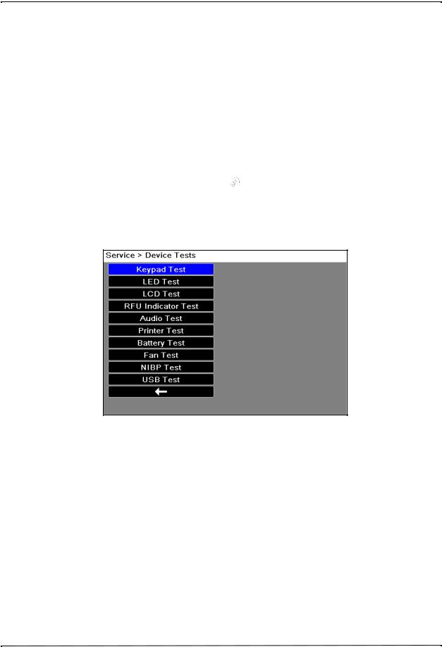
3.Use the navigation keys to select Supervisor>Service>Device Tests. The operational tests are displayed. Use the navigation keys to select one of the tests.
Note: You need a supervisor passcode to enter the Supervisor menu.
9650-001356-01 Rev. D |
ZOLL X Series Service Manual |
9 |

CHAPTER 1 MAINTENANCE TESTS
2.1 Keypad Test
This test checks all the front panel buttons on the unit to make sure they are working correctly.
Follow the instructions and use the navigation keys to move around the display and make selections.
Note: To exit screen after test is complete, press the “Enter” button 3 times to display arrow.
2.2 LED Test
This test checks all the Light Emitting Diodes in the unit to make sure they are working correctly.
Follow the instructions and use the navigation keys to move around the display and make selections.
Note: The speed of the flash varies by color.
10 |
9650-001356-01 Rev. D |
Maintenance Tests
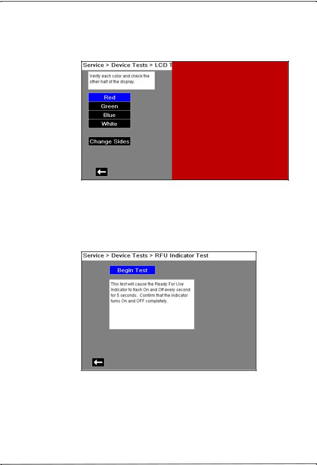
2.3 LCD Test
This test checks the colors of the Liquid Crystal Display on the unit.
Follow the instructions and use the navigation keys to move around the display and make selections.
2.4 RFU Indicator Test
This test checks the Ready For Use Indicator on the unit to make sure it is working correctly. Follow the instructions shown on the display.
9650-001356-01 Rev. D |
ZOLL X Series Service Manual |
11 |
CHAPTER 1 MAINTENANCE TESTS
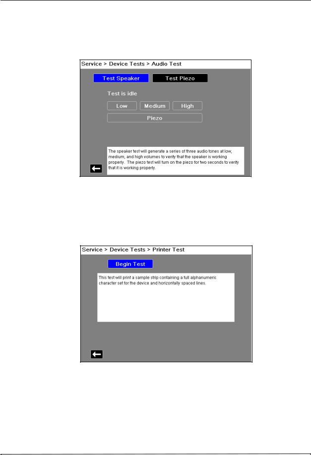
2.5 Audio Test
This test checks the audio tones on the unit to make sure they are working correctly.
Follow the instructions and use the navigation keys to move around the display and make selections.
2.6 Printer Test
This test checks the printer to make sure it is working correctly. Follow the instructions shown on the display.
12 |
9650-001356-01 Rev. D |
Maintenance Tests
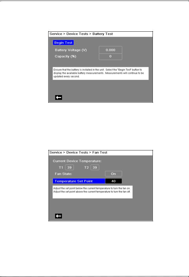
2.7 Battery Test
This test checks the battery to make sure it is working correctly. Follow the instructions on the display.
2.8 Fan Test
This test checks the fan in the unit to make sure it is working correctly.
Follow the instructions and use the navigation keys to move around the display and make selections.
9650-001356-01 Rev. D |
ZOLL X Series Service Manual |
13 |
CHAPTER 1 MAINTENANCE TESTS
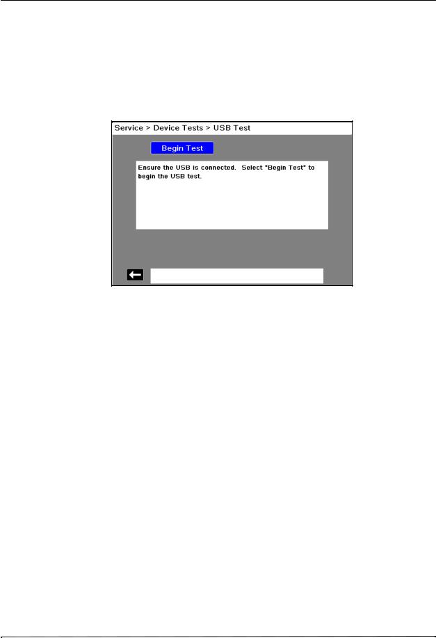
2.9 USB Test (Optional)
Note: Before starting this test, contact the ZOLL Technical Service Department to obtain a test file, or create a file (see instructions below). Once you have obtained a copy, save it on a USB thumb drive.
This test allows you to perform the USB test to make sure it is working correctly.
Follow the instructions and use the navigation keys to move around the display and make selections.
When these tests are completed, use the navigation keys to exit out of the Service menu.
Creating a Test File
1.Create a Text file using Microsoft Notepad.
2.Open new file in Notebook.
3.Click in the first line of the file and type “Thunderbolt Testfile".
4.Save file as Tbolt_usb.txt.
14 |
9650-001356-01 Rev. D |
Maintenance Tests
3.0 Leads Test
Equipment 3-lead, 5-lead, and 12-lead cables, Fluke Impulse 7000DP Analyzer Note: Test each cable separately.
Test Setup |
Connect the lead wires appropriate for each test to the Fluke Impulse 7000DP Analyzer or |
|
||||||
|
equivalent, then connect the ECG cable to the X Series unit. |
|
|
|
|
|||
|
|
|
|
|
|
|
||
|
|
Do this... |
Observe this... |
|
|
Pass/Fail |
||
|
|
|
|
|
|
|
|
|
|
3.1 |
Turn on the X Series unit. |
No ECG LEAD FAULT message |
|
|
o |
o |
|
|
|
Note: Make sure the lead is not |
displayed. |
|
|
|
|
|
|
|
displayed. |
|
|
|
|
|
|
|
|
|
|
|
|
|
||
|
3.2 |
Disconnect one lead from the |
The ECG LEAD FAULT message displays |
o |
o |
|||
|
|
simulator. |
within 3 seconds (if configured). |
|
|
|
|
|
|
|
|
|
|
|
|
||
|
3.3 |
Reconnect the lead. Repeat step 2 |
Wait for ECG LEAD FAULT message to |
o |
o |
|||
|
|
with the remaining leads. |
clear from the display (if configured). |
|
|
|||
|
|
|
|
|
|
|
||
|
3.4 |
Repeat steps 2 and 3 for 5 lead and 12 |
Note: If heart rate alarm sounds, on the |
o |
o |
|||
|
|
lead cables. |
X Series unit: |
|
|
|
|
|
|
|
|
Press the More quick access key ( |
) key |
|
|
||
|
|
|
to access the second set of quick access |
|
|
|||
|
|
|
keys. |
|
|
|
|
|
|
|
|
Press the Alarm quick access key ( |
|
). |
|
|
|
|
|
|
|
|
|
|||
|
|
|
Press the Alarm Cancel quick access key |
|
|
|||
|
|
|
( |
). |
|
|
|
|
|
|
|
|
|
|
|
|
|
9650-001356-01 Rev. D |
ZOLL X Series Service Manual |
15 |

CHAPTER 1 MAINTENANCE TESTS
4.0 Heart Rate Display Test
Equipment |
Fluke Impulse 7000DP Analyzer |
|
|
|
|
ECG Cable (3-lead, 5-lead or 12-lead) |
|
|
|
Test Setup |
Press Lead quick access key until II displays. |
|
||
|
Connect the ECG leads to the ECG studs on Analyzer. |
|
||
|
|
|
|
|
|
|
Do this... |
Observe this... |
Pass/Fail |
|
|
|
|
|
|
4.1 |
Set the ECG Simulator to 120BPM. |
The Heart Rate displays as 120 +/- 4 bpm. |
o o |
|
|
|
|
|
16 |
9650-001356-01 Rev. D |

Maintenance Tests
5.0 Heart Rate Alarm Test
Equipment |
Fluke Impulse 7000DP Analyzer |
|
|
|
|
||||
|
|
|
|
|
|
|
|
||
|
|
Do this... |
|
|
Observe this... |
Pass/Fail |
|||
|
|
|
|
|
|
|
|||
|
5.1 |
Press the Leads quick access key |
II displays next to the Leads quick |
o |
o |
||||
|
|
( |
IIII, ...II, ) on the X Series unit and |
|
access key. |
|
|
||
|
|
select lead II. |
|
|
|
|
|
||
|
|
|
|
|
|
|
|
|
|
|
5.2 |
On the X Series unit: |
|
|
The Alarm Settings menu displays. |
o |
o |
||
|
|
|
• Press the More quick |
|
|
|
|
||
|
|
|
access key ( |
) key to |
|
|
|
||
|
|
|
access the second set of |
|
|
|
|||
|
|
|
quick access keys. |
|
|
|
|
||
|
|
|
• Press the Alarm quick |
|
|
|
|
||
|
|
|
access key ( |
|
). |
|
|
|
|
|
|
|
• Press the Limits softkey. |
|
|
|
|||
|
5.3 |
On the X Series unit, select HR/PR |
|
|
|
||||
|
|
Alarm in the Alarm Settings menu |
|
|
|
||||
|
|
and use the navigation keys to do |
|
|
|
||||
|
|
the following: |
|
|
|
|
|
||
|
|
|
• Set the Upper Limit Enable |
|
|
|
|||
|
|
|
to ON. |
|
|
|
|
|
|
|
|
|
• Set the Lower Limit |
|
|
|
|
||
|
|
|
Enable to ON. |
|
|
|
|
|
|
|
|
|
• Set the Lower limit to 35. |
|
|
|
|||
|
|
|
• Set the Upper limit to 150. |
|
|
|
|||
|
|
Use the navigation keys to exit the |
|
|
|
||||
|
|
Alarm Settings menu. |
|
|
|
|
|
||
|
|
|
|
|
|
|
|
||
|
5.4 |
On the X Series unit, press the |
|
The red alarm suspension timer |
|
|
|||
|
|
Alarm Cancel quick access key |
|
displays at the top of the screen next |
|
|
|||
|
|
( |
). |
|
|
|
to the message area. |
|
|
|
|
|
|
|
|
|
|
||
|
|
|
|
|
|
|
|||
|
5.5 |
Remove a lead wire from the ECG |
The ECG LEAD FAULT message |
o |
o |
||||
|
|
simulator. |
|
|
displays. |
|
|
||
|
5.6 |
On the X Series unit, press |
. |
The Alarm Suspend key flashes. |
|
|
|||
|
|
|
|
|
|
|
|||
|
5.7 |
Reattach ECG Lead wire to ECG |
The ECG LEAD FAULT message no |
o |
o |
||||
|
|
simulator. |
|
|
longer displays. |
|
|
||
|
5.8 |
Set simulator to 30 BPM or lower. |
Heart Rate Value is highlighted and |
|
|
||||
|
|
|
|
|
|
|
the alarm tone sounds. The HR/PR |
|
|
|
|
|
|
|
|
|
LOW ALARM message displays. |
|
|
|
|
|
|
|
|
|
|
||
|
5.9 |
On the X Series unit, press |
. |
The Alarm Suspend key flashes. The |
o |
o |
|||
|
|
|
|
|
|
|
red alarm suspension timer displays |
|
|
|
|
|
|
|
|
|
at the top of the screen next to the |
|
|
|
|
|
|
|
|
|
message area. |
|
|
|
|
|
|
|
|
|
|
||
|
5.10 |
Set the simulator to 120 BPM. |
|
|
|
|
|||
|
|
|
|
|
|
|
|
||
|
5.11 |
On the X Series unit, press |
. |
Alarm is enabled. The alarm suspend |
o |
o |
|||
|
|
|
|
|
|
|
key flashes. The alarm suspension |
|
|
|
|
|
|
|
|
|
timer disappears. |
|
|
|
|
|
|
|
|
|
|
|
|
9650-001356-01 Rev. D |
ZOLL X Series Service Manual |
17 |

CHAPTER 1 MAINTENANCE TESTS
|
Do this... |
Observe this... |
Pass/Fail |
||
|
|
|
|
|
|
5.12 |
Set simulator to 160 BPM or higher. |
Heart Rate Value is highlighted and |
o |
o |
|
|
|
|
the alarm tone sounds. The HR/PR |
|
|
|
|
|
HIGH ALARM message displays. |
|
|
|
|
|
|
|
|
5.13 |
On the X Series unit, press the |
Alarm is suspended for 90 seconds. |
o |
o |
|
|
Alarm Silence/Reset button |
The alarm suspension timer appears |
|
|
|
|
( |
). |
in black. |
|
|
|
|
|
|
||
|
|
|
|
|
|
18 |
9650-001356-01 Rev. D |

Maintenance Tests
6.0 Power Supply Test
Equipment Battery Current Test Fixture (P/N 9100-3055-TF), Power Supply, Digital Multi-meter.
Test Setup
1.Set the Power Supply to 12V VDC 10 A.
2.Turn off the Power Supply output.
3.Connect the positive (PS+) post of the Power Supply to the positive (PS+) post (PS Red) of the Battery Current Test Fixture.
4.Connect the negative (PS-) post of the Power Supply to the negative (PS-) post (PS Black) of the Battery Current Test Fixture.
5.With the Battery Current Test Fixture out of the battery well, turn on the Power Supply output.
6.Set the Digital Multi-meter to measure DC I DC Amps.
7.Set the rear/front switch on the Digital Multi-meter to rear.
8.Connect the Digital Multi-meter (I+) terminal of the Battery Current Test Fixture to the red terminal (I) on the back of the Digital Multi-meter.
9.Connect Digital Multi-meter (I-) terminal of the Battery Current Test Fixture to the black terminal (LO) on the back of the Digital Multi-meter.
|
Do this... |
Observe this... |
Pass/Fail |
|
|
|
|
6.1 |
Install the Battery Current Test |
|
|
|
Fixture into battery well and wait |
|
|
|
about five seconds. |
|
|
|
|
|
|
6.2 |
Make sure the X Series unit is |
|
|
|
turned off. |
|
|
|
|
|
|
6.3 |
Press the I Measure switch on the |
Verify that the reading on the digital |
o o |
|
Battery Current Test Fixture. |
multi-meter is between |
|
|
|
0.583mA-0.770mA. |
|
|
|
|
|
6.4 |
Turn on the X Series unit, and wait |
|
|
|
about ten seconds until the power |
|
|
|
has stabilized. |
|
|
|
|
|
|
9650-001356-01 Rev. D |
ZOLL X Series Service Manual |
19 |

CHAPTER 1 MAINTENANCE TESTS
...Do this |
...Observe this |
Pass/Fail |
|
|
|
6.5On the X Series unit, do the following:
•Press the More ( ) then the Setup (
 ) quick access keys.
•Use the navigation keys to select Supervisor>Display/
Configuration>Device Info and select Restore All Factory Defaults.
|
Note: You need a supervisor |
|
|
|
passcode to enter the Supervisor |
|
|
|
menu. Also the unit will reboot |
|
|
|
during the of restoring factory |
|
|
|
defaults. |
|
|
|
|
|
|
6.6 |
Press the I Measure switch on the |
Observe the current measurement on |
o o |
|
Battery Current Test Fixture. |
the DMM, and verify that the reading |
|
|
|
is between 0.47A-1.25A. |
|
20 |
9650-001356-01 Rev. D |

Maintenance Tests
7.0 Leakage Current Test
Equipment See the manufacturer’s instructions or supplied specifications for the leakage tester you use.
Setup |
See the manufacturer’s instructions or supplied specifications for the leakage tester you use. |
|||||||||
|
Repeat leakage test with accessories: MFC, external paddles, internal paddles, and anterior/ |
|||||||||
|
posterior paddles. Perform these tests at the line-power voltage and frequency used in your |
|||||||||
|
installation. |
|
|
|
|
|
|
|
|
|
|
|
|
|
|
|
|
|
|
|
|
|
|
|
|
Maximum Leakage Acceptance Limits |
|
|||||
|
|
|
|
Patient Leakage |
|
Mains on Applied Part |
|
|||
|
|
|
|
|
|
|
|
|
|
|
|
|
Normal |
Single Fault |
|
Single Fault |
|
||||
|
|
|
|
|
|
|
|
|
|
|
|
ECG |
10 |
|
50 |
|
100 |
|
|||
|
|
|
|
|
|
|
|
|
|
|
|
MFC |
10 |
|
50 |
|
100 |
|
|||
|
|
|
|
|
|
|
|
|
|
|
|
|
|
|
|
|
|
|
|
|
|
|
|
|
|
Normal |
|
Single Fault |
|
|
|
|
|
|
|
|
|
|
|
|
|
||
|
Earth Leakage |
|
2500 |
|
5000 |
|
|
|
||
|
|
|
|
|
|
|
|
|
|
|
9650-001356-01 Rev. D |
ZOLL X Series Service Manual |
21 |

CHAPTER 1 MAINTENANCE TESTS
8.0 Shock Test
WARNING! Take the necessary precautions to guard against shock or injury before you start conducting the defibrillator tests.
Keep hands and all other objects clear of the multi-function cable connections and defibrillator analyzer when discharging the defibrillator.
Before you discharge the defibrillator, warn everyone near the equipment to STAND CLEAR.
Equipment Fluke Impulse 7000 DP Analyzer (or equivalent), stop watch
...Do This |
...Observe This |
Pass/Fail |
|
|
|
8.1Turn on the Analyzer.
8.2On the Analyzer, select the DEFIB function.
8.3On the Analyzer, select ENERGY.
8.4Connect the X Series MFC connector to the pads connection.
8.5On the X Series unit, apply power to the unit using a battery or an AC adapter.
8.6Connect the MFC cable to the X Series unit.
8.7Turn on the X Series unit, and press the
Leads quick access key ( I,IIIII,... ) to select
PADS.
8.8On the X Series unit, set energy level to 5J by pressing the Energy Select DOWN arrow.
8.9 On the X Series unit, press the CHARGE |
The unit charges to 5J, the red |
o o |
button. |
Shock button illuminates and a |
|
|
ready tone sounds. |
|
8.10 On the X Series unit, press the Shock button.
8.11 On the Analyzer, observe and record the |
Energy is delivered at 5J. Verify o o |
energy measurement. |
that the delivered energy is within |
|
15% based on the values in the |
|
table “Delivered Energy at 200J |
|
Defibrillator Setting into a Range |
|
of Loads” on page 24. |
8.12On the X Series unit, set the energy level to 50J by pressing the Energy Select UP arrow.
8.13 On the X Series unit, press the CHARGE |
The unit charges to 50J, the red |
o o |
button. |
Shock button illuminates and a |
|
|
ready tone sounds. |
|
22 |
9650-001356-01 Rev. D |

Maintenance Tests
|
Do This... |
Observe This... |
Pass/Fail |
|
|
|
|
|
|
8.14 |
On the X Series unit, press the Shock button. |
|
|
|
|
|
|
|
|
8.15 |
On the Analyzer, observe and record the |
Energy is delivered at 50J. Verify |
o |
o |
|
energy measurement. |
that the delivered energy is within |
|
|
|
|
15% based on the values in the |
|
|
|
|
table “Delivered Energy at 200J |
|
|
|
|
Defibrillator Setting into a Range |
|
|
|
|
of Loads” on page 24. |
|
|
|
|
|
|
|
8.16 |
On the X Series unit, set energy level to 100J |
|
|
|
|
by pressing the Energy Select UP arrow. |
|
|
|
|
|
|
|
|
8.17 |
On the X Series unit, press the CHARGE |
The unit charges to 100J, the |
o |
o |
|
button. |
Shock button illuminates and a |
|
|
|
|
ready tone sounds. |
|
|
|
|
|
|
|
8.18 |
On the X Series unit, press the Shock button. |
|
|
|
|
|
|
|
|
8.19 |
On the Analyzer, observe and record the |
Energy is delivered at 100J. |
o |
o |
|
energy measurement. |
Verify that the delivered energy is |
|
|
|
|
within 15% based on the values in |
|
|
|
|
the table “Delivered Energy at |
|
|
|
|
200J Defibrillator Setting into a |
|
|
|
|
Range of Loads” on page 24. |
|
|
|
|
|
|
|
8.20 |
On the X Series unit, set energy level to 200J |
|
|
|
|
by pressing the Energy Select UP arrow. |
|
|
|
|
|
|
|
|
8.21 |
On the X Series unit, press the CHARGE |
The unit charges to 200J, the red |
o |
o |
|
button. |
Shock button illuminates and a |
|
|
|
|
ready tone sounds. |
|
|
|
|
|
|
|
8.22 |
On the X Series unit, press the Shock button. |
|
|
|
|
|
|
|
|
8.23 |
On the Analyzer, observe and record the |
Energy is delivered at 200J. |
o |
o |
|
energy measurement. |
Verify that the delivered energy is |
|
|
|
|
within 15% based on the values in |
|
|
|
|
the table “Delivered Energy at |
|
|
|
|
200J Defibrillator Setting into a |
|
|
|
|
Range of Loads” on page 24. |
|
|
|
|
|
|
|
8.24 |
On the X Series unit, press the CHARGE |
The unit charges to 200J, the red |
o |
o |
|
button. |
Shock button illuminates, and a |
|
|
|
|
ready tone sounds. |
|
|
|
|
|
|
|
8.25 |
When the X Series unit is charged, start the |
Verify that after 50 seconds the |
o |
o |
|
stop watch. |
tone changes and within 10 |
|
|
|
|
seconds the unit does an internal |
|
|
|
|
discharge and displays |
|
|
|
|
DISARMED TIMEOUT. |
|
|
|
|
|
|
|
8.26 |
Turn off the X Series unit. |
|
|
|
|
|
|
|
|
9650-001356-01 Rev. D |
ZOLL X Series Service Manual |
23 |

CHAPTER 1 MAINTENANCE TESTS
Delivered Energy at 200J Defibrillator Setting into a Range of Loads
Selected |
|
|
|
Load |
|
|
|
|
Energy |
25 |
50 |
75 |
100 |
125 |
150 |
175 |
Accuracy* |
5 J |
3 J |
5 J |
6 J |
6 J |
6 J |
6 J |
6 J |
±15% |
|
|
|
|
|
|
|
|
|
50 J |
35 J |
54 J |
59 J |
61 J |
62 J |
61 J |
59 J |
±15% |
|
|
|
|
|
|
|
|
|
100 J |
71 J |
109 J |
119 J |
122 J |
125 J |
123 J |
119 J |
±15% |
|
|
|
|
|
|
|
|
|
200 J |
142 J |
230 J |
249 J |
253 J |
269 J |
261 J |
260 J |
±15% |
|
|
|
|
|
|
|
|
|
Note: For a complete listing of X Series Delivered Energy at Every Defibrillator Setting into a Range of Loads, see Appendix A in the X Series Operator’s Guide.
24 |
9650-001356-01 Rev. D |
Loading...