


www.zephyronline.com
APEX
DAP-M90AMBX
DAP-M90AMWX
RANGE HOOD - Installation instructions
ENGLISH.......................... |
3 |
FRANÇAIS....................... |
27 |
Table of Contents
SAFETY INSTRUCTIONS.................................................................................................. |
pag. 4 |
LIST OF MATERIALS........................................................................................................... |
pag. 8 |
DUCTING CALCULATION SHEETS....................................................................................... |
pag. 9 |
HOODSPECIFICATION.................................................................................................... |
pag.10 |
INSTALLATION |
|
- INTERNAL BLOWER..................................................................................... |
pag. 11 |
- EXTERNAL & IN-LINE BLOWER PREPARATION............................... |
pag. 14 |
- DUCTING OPTIONS..................................................................................... |
pag. 17 |
- MOUNTING THE RANGE HOOD............................................................. |
pag. 18 |
- POWER SUPPLY CONNECTION.............................................................. |
pag. 19 |
TOUCH CONTROL............................................................................................................ |
pag. 20 |
OPTIONAL REMOTE CONTROL.................................................................................. |
pag. 21 |
MAINTENANCE ................................................................................................................ |
pag. 22 |
WIRING DIAGRAMS........................................................................................................ |
pag. 23 |
LIST OF PARTS AND ACCESSORIES ........................................................................ |
pag. 25 |
WARRANTY ....................................................................................................................... |
pag. 26 |
- 3 -

Safety instructions 1/4
IMPORTANT SAFETY INSTRUCTIONS
FOR RESIDENTIAL USE ONLY
READ AND SAVE THESE INSTRUCTIONS
PLEASE READ ENTIRE INSTRUCTIONS BEFORE PROCEEDING. IMPORTANT: Save these Instructions for the Local Electrical Inspectors use. INSTALLER: Please leave these Instructions with this unit for the owner. OWNER: Please retain these instructions for future reference.
Take care when using cleaning agents or detergents.
Suitable for use in household cooking area.
WARNING - To reduce the risk of fire or electric shock, do not use this fan with any Solid-State Speed Control Device.
CAUTION - To reduce risk of fire and to properly exhaust air, be sure to duct air outside – Do not vent exhaust air into spaces within walls or ceilings or into attics, crawl spaces, or garages.
CAUTION - For general ventilating use only. Do not use to exhaust hazardous or explosive materials and vapors.
CAUTION - To avoid motor bearing damage and noisy and/or unbalanced impellers, keep drywall spray, construction dust, etc. off power unit.
CAUTION - Please read specification label on product for further information and requirements.
WARNING – TO REDUCE THE RISK OF FIRE, ELECTRIC SHOCK, OR INJURY TO PERSONS, OBSERVE THE FOLLOWING:
A.Use this unit only in the manner intended by the manufacturer. If you have questions, contact the manufacturer.
B.Before servicing or cleaning unit, switch power off at service panel and lock the service disconnecting means to prevent power from being switched on accidentally. When the service disconnecting means cannot be locked, securely fasten a prominent warning device, such as a tag, to the service panel.
WARNING - TO REDUCE THE RISK OF A RANGE TOP GREASE FIRE:
A.Never leave surface units unattended at high settings. Boilovers cause smok
-4 -

Safety instructions 2/4
ing and greasy spillovers that may ignite. Heat oils slowly on low or medium settings.
B.Always turn hood ON when cooking at high heat or when flambeing foods ( i.e. Crepes Suzette, Cherries Jubilee, Peppercorn Beef Flambè ).
C.Clean ventilating fans frequently. Grease should not be allowed to accumulate on fan or filter.
D.Use proper pan size. Always use cookware appropriate for the size of the surface element.
E.Keep fan, filters and grease laden surface clean.
F.Use high range setting on range only when necessary. Heat oil slowly on low to medium setting.
G.Don’ t leave range unattended when cooking.
H.Always use cookware and utensils appropriate for the type and amount off food being prepared.
WARNING – TO REDUCE THE RISK OF INJURY TO PERSONS IN THE EVENT OF A RANGE TOP GREASE FIRE, OBSERVE THE FOLLOWINGa:
A.SMOTHER FLAMES with a close-fitting lid, cookie sheet, or metal tray, then turn off the burner. BE CAREFUL TO PREVENT BURNS. If the flames do not go out immediately, EVACUATE AND CALL THE FIRE DEPARTMENT.
B.NEVER PICK UP A FLAMING PAN – You may be burned.
C.DO NOT USE WATER, including wet dishcloths or towels – a violent steam explosion will result.
D.Use an extinguisher ONLY if:
1.You know you have a Class ABC extinguisher, and you already know how to operate it.
2.The fire is small and contained in the area where it started.
3.The fire department is being called.
4.You can fight the fire with your back to an exit.
aBased on “kitchen firesafety tips” published by NFPA
Proper maintenance of the Range Hood will assure proper performance of the unit.
INSTALLATION INSTRUCTIONS
WARNING – TO REDUCE THE RISK OF FIRE, ELECTRIC SHOCK, OR INJURY TO PERSONS, OBSERVE THE FOLLOWING:
A.Installation work and electrical wiring must be done by qualified person(s) in accordance with all applicable codes and standards, including fire-rated construction.
-5 -

Safety instructions 3/4
B.Sufficient air is needed for proper combustion and exhausting of gases through the flue (chimney) of fuel burning equipment to prevent back drafting. Follow the heating equipment manufacturer’s guideline and safety standards such as those published by the National Fire Protection Association (NFPA), and the American Society for Heating, Refrigeration and Air Conditioning Engineers (ASHRAE), and the local code authorities.
C.When cutting or drilling into wall or ceiling, do not damage electrical wiring and other hidden utilities.
D.Ducted fans must always be vented to the outdoors.
E.This unit must be grounded.
WARNING - TO REDUCE THE RISK OF FIRE, USE ONLY METAL DUCTWORK.
WARNING - UNDER CERTAIN CIRCUMSTANCES DOMESTIC APPLIANCES MAY BE DANGEROUS.
A.Do not check filters with hood working.
B.Do not touch the lamps after a prolonged use of the appliance.
C.No food must be cooked flambè underneath the hood.
D.The use of an unprotected flame is dangerous for the filters and could cause fires.
E.Watch constantly the fried food in order to avoid the cooking oil flares up.
F.Before performing any mainteinance operation, disconnect the hood from the electrical service.
The manufacturers will not to accept any responsibility for eventual damages, because of failure to observe the above instructions.
Electrical Requirements
Important:
-Observe all governing codes and ordinances.
-It is the customer’s responsibility to be aware of these below:
-To contact a qualified electrical installer.
-To assure that the electrical installation is adequate and in conformance with National Electrical Code, ANSI/NFPA 70 latest edition* or CSA standards C22.1- 94, Canadian Electrical Code, Part 1 and C22.2 No.0-M91 - latest edition** and all local codes and ordinances.
-If codes permit and a separate ground wire is used, it is recommended that a qualified electrician determine that the ground path is adequate.
-Do not ground to a gas pipe.
-Check with a qualified electrician if you are not sure the range hood is properly grounded.
-6 -

Safety instructions 4/4
-Do not have a fuse in the neutral or ground circuit.
-This appliance requires a 120V 60Hz electrical supply and connected to an individual properly grounded branch circuit protected by a 15 or 20 ampere circuit breaker or time delay fuse. Wiring must be 2 wire with ground. Please also refer to Electrical Diagram on product.
-A cable locking connector (not supplied) might also be required by local codes. Check with local requirements, purchase and install appropriate connector if necessary.
* National Fire Protection Association Batterymarch Park, Quincy, Massachusetts 02269
** CSA International 8501 East Pleasant Valley Road, Cleveland, Ohio 44131-5575
Federal Communication Commission Interface Statement
-This equipment has been tested and found to comply with the limits for a Class B digital device, pursuant to Part 15 of the FCC Rules. These limits are designed to provide reasonable protection against harmful interference in a residential installation.
-This equipment generates, uses and can radiate radio frequency energy and, if not installed and used in accordance with the instructions, may cause harmful interference to radio communications. However, there is no guarantee that interference will not occur in a particular installation. If this equipment does cause harmful interference to radio or television reception, which can be determined by turning the equipment off and on, the user is encouraged to try to correct the interference by one of the following measures:
-Reorient or relocate the receiving antenna.
-Increase the separation between the equipment and receiver.
-Connect the equipment into an outlet on a circuit different from that to which the receiver is connected.
-Consult the dealer or an experienced radio/TV technician for help.
 WARNING Prop. 65 Warning for California Residents: This product may contain chemicals known to the State of California to cause cancer, birth defects, or other reproductive harm.
- 7 -
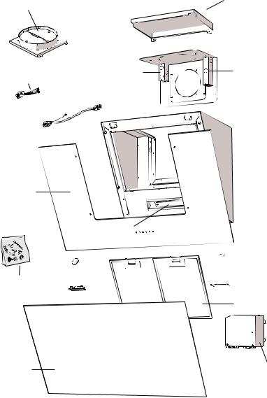
List of Materials
Remote Blower Collar with Damper
Remote Blower
Wiring Harness
Remote Blower 
Wiring Extension
Glass
Hardware
Panel
Box marked '120 VAC input'
Control
Top Cover
Remote Blower
Box

 Blower Bracket

 Magnet

 Led Light
Filters
Electrical
System Box
- 8 -
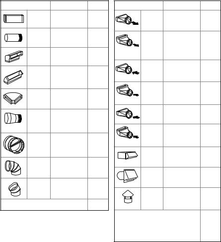
Ducting Calculation Sheet
Duct pieces |
Equivalent number |
Total |
|||
|
length x used |
|
= |
||
3-1/ 4” x 10” |
1 Ft. |
x ( |
) |
= |
Ft. |
Rect., |
|
|
|
|
|
straight |
|
|
|
|
|
6”, 7”, 8”, 10” |
1 Ft. |
x ( |
) |
= |
Ft. |
Round, |
|
|
|
|
|
straight |
|
|
|
|
|
3-1/ 4” x 10” |
15 Ft. |
x ( |
) |
= |
Ft. |
Rect.900 |
|
|
|
|
|
elbow |
|
|
|
|
|
3-1/ 4” x 10” |
9 Ft. |
x ( |
) |
= |
Ft. |
Rect.450 |
|
|
|
|
|
elbow |
|
|
|
|
|
3-1/ 4” x 10” |
24 Ft. |
x ( |
) |
= |
Ft. |
Rect.900 |
|
|
|
|
|
flat elbow |
|
|
|
|
|
7” to 6” or |
25 Ft. |
x ( |
) |
= |
Ft. |
8” to 7” Round |
|
|
|
|
|
tapered |
|
|
|
|
|
reducer |
|
|
|
|
|
6”, 7“, 8” |
15 Ft. |
x ( |
) |
= |
Ft. |
Round |
|
|
|
|
|
in-line |
|
|
|
|
|
damper |
|
|
|
|
|
6”, 7”, 8”, 10” |
15 Ft. |
x ( |
) |
= |
Ft. |
Round, |
|
|
|
|
|
900 elbow |
|
|
|
|
|
6”, 7”, 8”, 10” |
9 Ft. |
x ( |
) |
= |
Ft. |
Round, |
|
|
|
|
|
450 elbow |
|
|
|
|
|
|
Subtotal column 1 = |
Ft. |
|||
Maximum Duct Length: For satisfactory air movement, the total duct length should not exceed 150 equivalent feet.
Duct pieces |
Equivalent number |
|
Total |
||
|
length x used |
= |
|
||
3-1/ 4” x 10” |
5 Ft. |
x ( |
) |
= |
Ft. |
Rect.to |
|
|
|
|
|
6” round |
|
|
|
|
|
transition |
|
|
|
|
|
3-1/ 4” x 10” |
20 Ft. |
x ( |
) |
= |
Ft. |
Rect.to |
|
|
|
|
|
6” round |
|
|
|
|
|
transition |
|
|
|
|
|
900 elbow |
|
|
|
|
|
6” round to |
1 Ft. |
x ( |
) |
= |
Ft. |
3-1/ 4” x 10” |
|
|
|
|
|
rect. |
|
|
|
|
|
transition |
|
|
|
|
|
6” round to |
16 Ft. |
x ( |
) |
= |
Ft. |
3-1/ 4” x 10” |
|
|
|
|
|
rect. |
|
|
|
|
|
transition |
|
|
|
|
|
900 elbow |
|
|
|
|
|
7” round to |
8 Ft. |
x ( |
) |
= |
Ft. |
3 1/ 4” x 10” |
|
|
|
|
|
rect. |
|
|
|
|
|
transition |
|
|
|
|
|
7” round to |
23 Ft. |
x ( |
) |
= |
Ft. |
3-1/ 4” x 10” |
|
|
|
|
|
rect. |
|
|
|
|
|
transition |
|
|
|
|
|
900 elbow |
|
|
|
|
|
3-1/ 4” x 10” |
30 Ft. |
x ( |
) |
= |
Ft. |
Rect. |
|
|
|
|
|
wall cap |
|
|
|
|
|
with damper |
|
|
|
|
|
6”, 7”, 8”, 10” |
30 Ft. |
x ( |
) |
= |
Ft. |
Round, wall |
|
|
|
|
|
cap with |
|
|
|
|
|
damper |
|
|
|
|
|
6”, 7”, 8”, 10” |
30 Ft. |
x ( |
) |
= |
Ft. |
Round |
|
|
|
|
|
roof cap |
|
|
|
|
|
Subtotal column 2 = |
Ft. |
|
Subtotal column 1 = |
|
|
Ft. |
||
Total ductwork |
= |
|
Ft. |
||
- 9 -
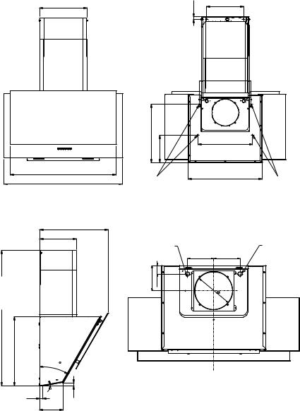
Hood Specifications
front of hood
14-1/16''
Optional
Duct Cover
31-1/2'' |
35-3/8'' |
side of hood
19-13/16''
10-9/16''
Z1C-00MExx |
|
(optional duct cover) |
Optional |
min. ducted - 50” |
Duct Cover |
max. - 60” |
|
| <![if ! IE]> <![endif]>19-3/4'' |
|
|
30 |
|
10 |
1'' |
<![if ! IE]> <![endif]>3/4'' |
|
6-3/4'' |
back of hood
| <![if ! IE]> <![endif]>11/16'' |
10-13/16'' |
|
Optional |
Duct Cover |
|
15-3/16'' |
| <![if ! IE]> <![endif]>17'' |
|
|
16'' |
| <![if ! IE]> <![endif]>8'' |
|
Holes for |
21-9/16'' |
wall installation |
|
Holes for
wall installation
top of hood
ELEC. KO |
REMOTE BLOWER KO |
|
5-7/16'' |
5-7/16'' |
| <![if ! IE]> <![endif]>5-3/16'' |
<![if ! IE]> <![endif]>3/4'' |
|
|
<![if ! IE]> <![endif]>1- |
|
|
|
6” |
|
|
or |
|
|
8' |
|
|
' |
- 10 -
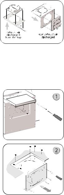
Installation - Internal Blower
 NOTE! The device in this version (with internal suction blower) is equipped for rear discharge of exhaust air. However, if required, it is possible to have the exhaust air discharged from the top. This can be accomplished by carrying out the steps indicated in the following paragraphs; upon reaching step 9, the motor plate must not be rotated.
 The following instructions are for installing the internal blower. CAUTION: To reduce the risk of fire and electric shock, install this rangehood only with internal blower models CBI-290A or CBI-600A.
For external and in-line blower preparation please turn to page 14.
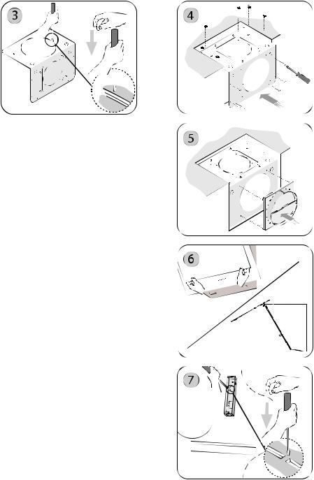
1. Remove the (2) screws securing the top cover. See Fig.1
2. Remove the 6” round metal knockout plate from the blower plate by using a flat head screwdriver. See Fig.2
3. Remove the (6) screws securing the blower plate to the blower housing and remove blower plate. See Fig.3
4. Install internal blower into blower plate and secure using (4) screws included with the blower. See Fig.4
- 11 -

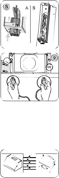
5. Secure capacitor box connected to the provided cable to the blower plate using
(2) screws included with the blower. See Fig.5
6.Secure Green/Yellow ground wire connected to the cable to the provided capacitor to blower plate. Fig.6
7.Open the front panel, Fig.7
NOTE! Open the front panel while holding it by its external sides, as shown in Fig.7, and keep at a suitable distance to avoid impacting it.
8.Attach the 6 pin male molex connector from blower wire to the 6 pin female molex connector located inside the blower housing. See Fig.8
9.Install the blower and plate on the inside of the blower housing: carry out the instructions at step 2 in reverse order then use the screws provided to complete installation. (Tot. 12). Fig.9
-12 -
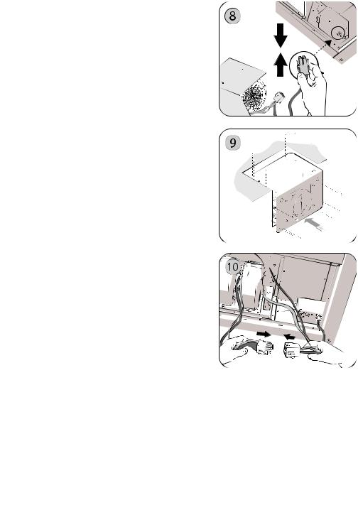
10. Connect 9 pin male molex connector from blower wire to 9 pin female molex connector on the capacitor wire. See Fig.10
WARNING! Place electrical wiring inside the blower housing.
11.Put the top cover back on.
12.Close the front panel.
The hood is now ready to be installed on the wall.
- 13 -
Installation - External & In-Line Blower
Preparation
 NOTE! The device in this version (with external blower) is equipped for rear discharge of exhaust air. However, if required, it is possible to have the exhaust air discharged from the top. This can be accomplished by carrying out the steps indicated in the following paragraphs; upon reaching step 4, the blower plate must be rotated and installed in the opposite direction.
 The following instructions are for preparing the hood for use with an external or in-line blowers models CBE-1000 or PBN-1000A.
CAUTION: To reduce the risk of fire and electric shock, install this rangehood only with remote blowers rated maximum 6.2 A.
For internal blower instructions please turn to page 11.
1. Remove the (2) screws securing the top cover. See Fig.1
2. Remove the (6) screws securing the blower plate to the blower housing and remove blower plate. See Fig.2
3.Remove the 8” round metal knockout plate from the blower plate by using a
flat head screwdriver. See Fig.3
4. Install the plate with the outlet facing the wall, inside the motor casing: carry out the instructions at stage 2 in reverse order then use the screws provided to complete installation. See Fig.4
- 14 -
5.Install the flange and fix it to the blower plate with the (4) screws. Fig. 5
6.Put the top cover back on.
7.Open the front panel, Fig.6
NOTE! Open the front panel while holding it by its external sides, as shown in Fig.7, and keep at a suitable distance to avoid impacting it.
8.With the aid of a slotted screwdriver, break the grommet of circular hole through which the wires pass. Fig. 7
9.Insert the female connector in the terminal box already attached to the hood. Fig. 8A
Pass the wires of the remote motor through the terminal box hole and connect them to the connector wires. Fig. 8B
Note: Carry out the power supplly connection in accordance with the national electric code, ANSI/NFPA 70-1999.
- 15 -
Note1: A cable lock (not included) may be required by local codes. Please review local codes for more information.
10. Attach 6 pin male molex connectors to
6 pin female molex connectors inside blower housing. See Fig. 9
Note2: Check local codes to determine minimum wire gauge.
11. Close the front panel.
See manual included with external and in-line blower for instructions on installing the blower.
- 16 -
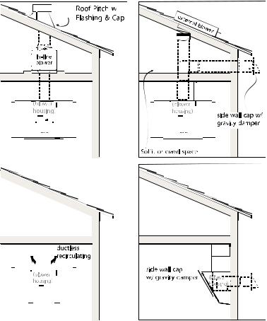
Installation - Ducting Options
 WARNING FIRE HAZARD
NEVER exhaust air or terminate duct work into spaces between walls, crawl spaces, ceiling, attics or garages.
All exhaust must be ducted to the outside, unless using the recirculating option.
Use single wall rigid Metal ductwork only.
Fasten all connections with sheet metal screws and tape all joints w/ certified Silver Tape or Duct Tape.
Some Ducting Options
- 17 -
 Loading...