


Zephyr AK2536W, AK2536B, AK6500B, AK2500S, AK2536S User Manual
...5SE #ARE ANDA)NSTALLATION 'UIDE
2EAD ALL )NSTRUCTIONSNBEFORE )NSTALLINGNAND OPERATINGRTHIS APPLIANCE
)MPORTANTR3AFETY .OTICE
2EAD AND SAVENTHESESINSTRUCTIONS
-/$%, !+ !+ !+ !+ !+
WARNING
TO REDUCE THE RISK OF FIRE OR ELECTRIC SHOCK, DO NOT USE THIS FAN WITH ANY SOLID-STATE CONTROL DEVICE.
WARNING
TO REDUCE THE RISK OF FIRE< ELECTRIC SHOCK, OR INJURY TO PERSONS, OBSERVCE THE FOLLOWING:
a.Use this unit only in the manner intended by the manufacturer, if you have questions, contact the manufacturer.
b.Before servicing or cleaning unit, switch power off at service panel and lock panel
to prevent power from being switched on accidentally. When the service disconnecting means cannot be locked, securely fasten a prominent warning device, such as a tag, to the service panel.
CAUTION
For general ventilating use only. Do not use to exhaust cigarette ashes, hazardous or explosive materials and vapors.
WARNING
TO REDUCE THE REISK OF RANGE TOP GREASE FIRE:
a.Never leave surface units unattended at high settings. Boilovers cause smoking and greasy spillovers that may ignite. Heat oils slowly on low or medium settings.
b.Always turn hood ON when cooking at high heat or when flambeing food (ie: Crepes Suzette, Cherries Jubilee, Peppercorn Beef Flambe)
c.Clean ventilating fans frequently. Grease should not be allowed to accumulate on fan or filter.
d.Use proper pan size. Always use cookware appropriate for the size of the surface element.
XP02243(2)
2EV
5SE #ARE ANDA)NSTALLATION 'UIDE
2EAD ALL )NSTRUCTIONSNBEFORE )NSTALLINGNAND OPERATINGRTHIS APPLIANCE
WARNING
TO REDUCE THE RISK OF FIRE, ELECTRIC SHOCK OR INJURY TO PERSONS, OBSERVE THE FOLLOWING:
a.Installation worka nd electrical wiring must be done by qualified person (s) in accordance with all applicable codes and standards. Including fire-rated construction.
b.Sufficient air is needed for power combustion and exhausting of gases through the flue (chimney) of fuel burning equipment to prevent back drafting. Follow the heating equipment manufacturer’s guideline and safety standards such as those published by teh National Fire Protection Association (NFPA) and the American Society for Heating, Refrigeration and Air Conditioning Engineers (ASHRAE) and the local code authorities.
c.When cuttig or drilling into wall or ceiling, do not damage electrical wiring and other hidden utilities.
d.Ducted fans must always vent to the outdoors.
WARNING
TO REDUCE THE RISK OF FIRE, USE ONLY METAL DUCTWORK.
CAUTION
To reduce risk of fire and to proerly exhaust air outside - Do not vent exhaust air into soaces within walls, ceilings, attics, crawl spaces or garages.
WARNING
TO REDUCE THE RISK OF SHOCK, THIS FAN MUST BE INSTALLED WITH AN ISOLATING WALL CONTROL/SWITCH.
OPERATION
Always leave safety grills and filters in place. WIthout these components, operating blowers could catch onto hair, fingers and loose clothing.
The manufacturer declines all responsibility in the event of failure to observer the instructions given here for installation, maintenance and suitable use of the product. The manufacturer further declines all responsibility for injury due to negligence and the warranty of the unit automatically expires due to improper maintenance.
*NOTE: Please check www.zephyronline.com for revisions before doing any custom work.

36".
Min. 26" - Max. 36"
INSTALLATION |
|
INSTALLATION |
|
|
|
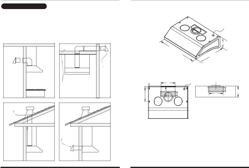
DUCTING
WARNING FIRE HAZARD
NEVER exhaust air or terminate duct work into spaces between walls, crawl spaces, ceiling,attics or garages. All exhaust must be ducted to the outside.
Use metal ductwork only.
Fasten all connections with sheet metal screws and tape all joints w/ certified Silver Tape or Duct Tape.
Some Ducting Options:
Side wall cap
w/ gravity damper
Side wall cap |
w/ gravity damper |
Soffit or crawl space |
Roof Pitch w/ |
|
Flashing & Cap |
|
Rear Ducting |
|
Models: AK6500, AK6536, AK6542, AK2500, AK2536 |
Page 2 |
SPECIFICATIONS
Elec K.O.
7-5/8"
30" 36"
42"
22-1/4"
TOP VIEW |
REAR VIEW |
1" |
10" |
Elec K.O. |
CL |
1-1/8" |
|
|
3/4" |
|
6-5/8" |
|
3-1/4" |
|
|
|
7-5/8" |
9" |
|
3-1/4" |
10" |
|
|
Models: AK6500, AK6536, AK6542, AK2500, AK2536 Page 3
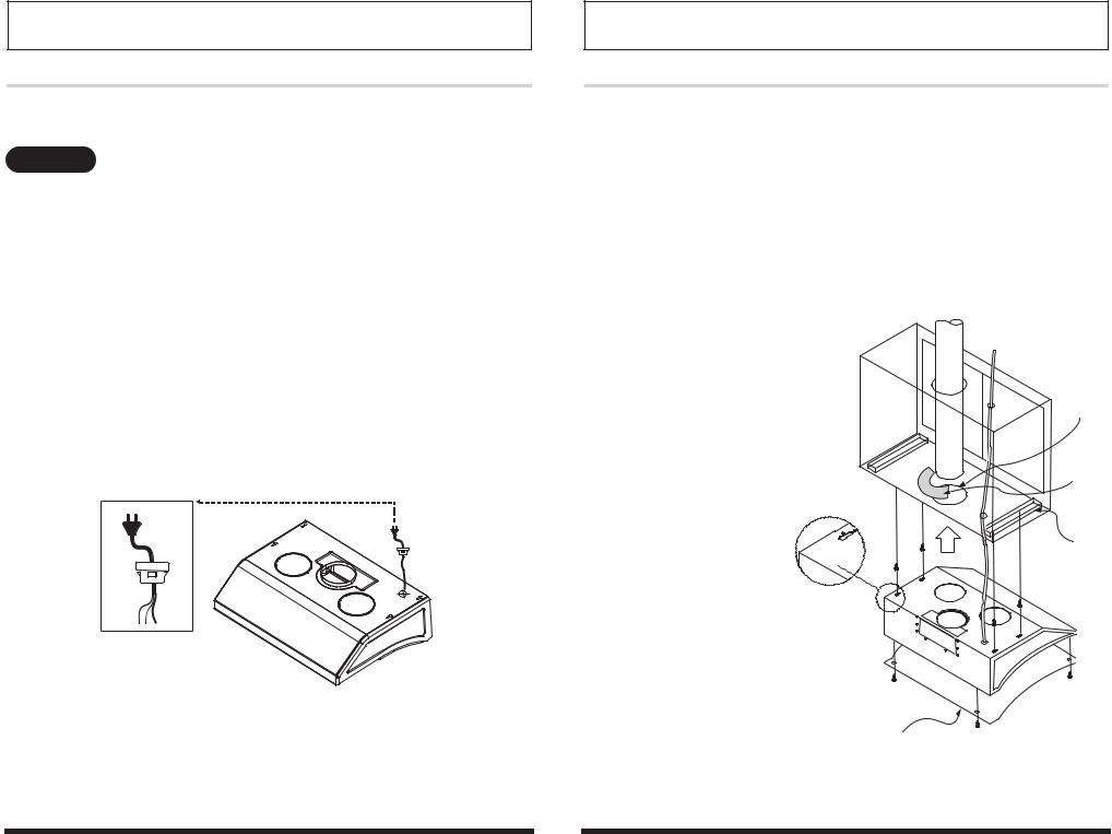
INSTALLATION
MOUNTING THE RANGEHOOD
ELECTRICAL
WARNING
All Electrical work must by performed by qualified electrician or person with similar technical know how and background.
For personal safety, remove house fuse or open circuit breaker before beginning installation. Do not use extension cord or adapter plug with this appliance.
Follow National electrical codes or prevailing local codes and ordinances.
Electrical Supply:
This appliance requires a 120V 60Hz electrical supply., and connected to an individual, properly grounded branch circuit, protected by a 15 or 20 ampere circuit breaker or time delay fuse. Wiring must be 2 wire w/ ground. Please also refer Electrical Diagram labeled on product.
Cable Lock:
A cable locking connector (not supplied) might also be required by local codes. Check with local requirements and codes, purchase and install appropriate connector if necessary.
Cable Lock
Models: AK6500, AK6536, AK6542, AK2500, AK2536 Page 4
INSTALLATION
MOUNTING THE RANGEHOOD
1.This range hood is mounted under a kitchen cabinet unit.
2.Select preferred duct location on rear or top of unit. (See page 6 & 7 for ducting conversion options)
3.Begin installation by temporarily unscrewing and removing the bottom splash panel.
4.Reinforce cabinet base with 1x2 wood strips if additional strengthening is required.
5.Temporarily position the range hood in the desired mounting location. Measure and mark the mounting holes,
duct and electrical access locations with a pencil.
6.Drill/cut out the required openings for duct and electrical access; make sure the duct opening is large enough to apply duct tape.
7.Fasten hood onto cabinet with screws and washers provided.
8.Install electrical.
9. Install duct work and duct-tape.
10. Reinstall the bottom splash panel.
11. Power up hood and check for leaks around duct-tape.
6.Duct opening cutout
duct/silver tape
4.Add 1x2 wood strips
3.Splash bottom panel
Models: AK6500, AK6536, AK6542, AK2500, AK2536 Page 5
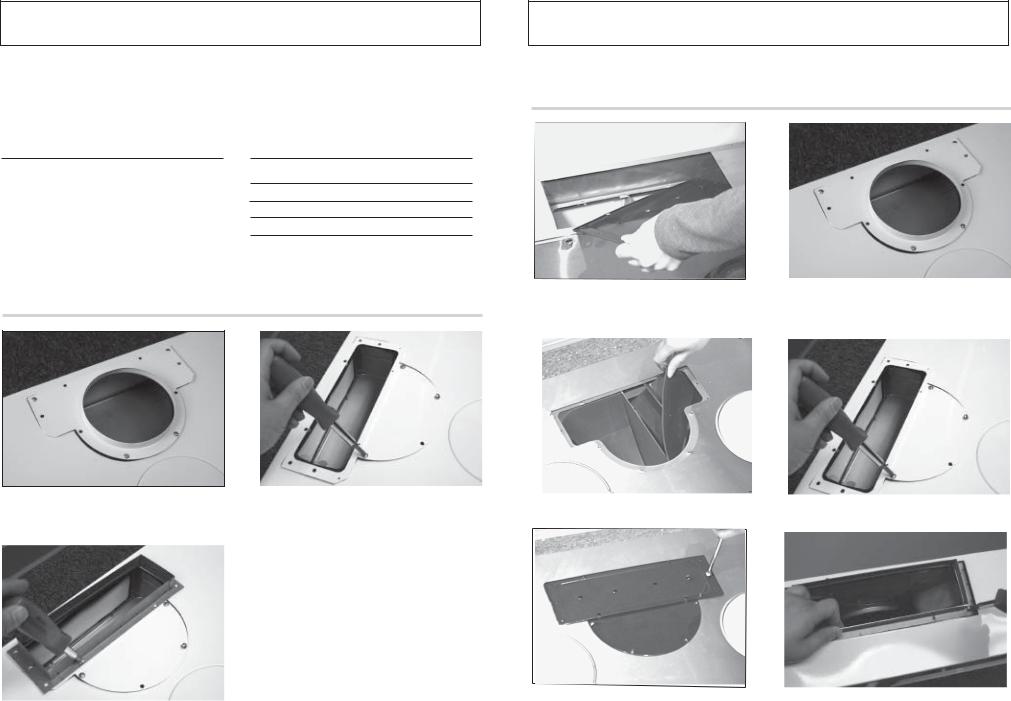
).34!,,!4)/. ).34!,,!4)/.
#/.6%24)",%"/04)/.3 |
|
#/.6%24)",%"/04)/.3 |
|
|
|
4HIS RANGENHOOD IS EQUIPPED WITH THEHOPTION OFFAA v VERTICAL DISCHARGE vX v VERTICAL DISCHARGE vX v 2EAR $ISCHARGE OR vX v REAR DISCHARGE !DDITIONAL ACCESSORIESSARERPROVIDED TO CONVERTVTO EITHER OF THEHABOVE
DISCHARGEHMETHODS
#ONVERTIBLER/PTIONS
6ERTICALIDISCHARGE |
v ROUND |
6ERTICALIDISCHARGE |
vX v |
(ORIZONTAL REAR DISCHARGE |
vX v |
|
|
#ONVERTIBLER!CCESORIES
2OUNDUTRANSITION ADAPTER
2ECTANGULARNTRANSITION ADAPTER
2ECTANGULARNREAR CAP PRE MOUNTED
vX v STARTING COLLAR
vX v 6ERTICALI$ISCHARGE
!T REAR OF RANGENHOOD REMOVE ALLLSCREWS ON PRE |
2EMOVE TOPOPRE MOUNTEDOTRANSITION PIECE |
MOUNTEDNREAR RECTANGULARNCAPPANDNREMOVE PLATE |
|
2EMOVE PRE MOUNTEDO v TRANSITION ADAPTER OR DUCT OPENING
|
|
|
|
|
|
|
|
|
|
0LACEARECTANGULARNTRANSITION ADAPTER AS SHOWN |
2EMOVE AIR DIVERTERIBLOCKS THROUGH TOP |
|
|
|
|
-OUNT RECTANGULARNTRANSITION PIECE TO TOP |
|
||
BY FIRSTRINSTALLING SCREWS ON HALF ROUND |
OPENINGNAS SHOWN A |
|
|
|
|
OPENINGNAS SHOWN A |
|
||
SECTION |
|
|
|
|
|
|
|
|
|
|
|
|
|
|
|
|
|
|
|
|
|
|
|
-OUNTURECTANGULARNPLATEA PREVIOUSLYIREMOVED |
ON -OUNTUSTARTING COLLAR PROVIDED AT REAR DISCHARGE |
|
|
-OUNTUTHEH vX v STARTING COLLAR ON TOPOOF |
|
|
TOP OF TRANSITION ADAPTER |
|
|
|
|
|
|
|
|
|
|
TRANSITION PIECEEWITH REMAININGISCREWS |
|
|
|
|
|
|
|
|
|
|
||
|
|
|
|
|
|
|
|
|
-ODELS !+ !+ !+ !+ !+0AGE |
-ODELS !+ !+ !+ !+ !+0AGE |
|||
 Loading...