

Page 1

User Manual
Carl Zeiss Spectroscopy GmbH
MCS 600
Page 2

Knowledge of this manual is required to operate the device. Please familiarize yourself with the contents of this
manual and give special attention to information that affects the safe handling of the device. We reserve the right
to make changes in the interest of technical improvements. The operating manual is not updated automatically.
© The passing on and reproduction of this document, exploitation and disclosure of its content are not allowed
unless expressly agreed to. Violations shall result in claims for damages. All rights reserved in the event of granting
of patents or registration of a utility model.
Carl Zeiss Spectroscopy GmbH
Carl-Zeiss-Promenade 10
07745 Jena, Germany
Service + 49 3641 64-1648
Headquarters + 49 3641 64-2838
Fax + 49 3641 64-2485
E-mail service.spectroscopy@zeiss.com
Internet www.zeiss.com/spectroscopy
Publication number: UM MCS 600 / E 2018-01
Edition 3, January 2018
Subject to change.
Page 3

3
MCS 600 | User Manual
MCS 600
Table of Contents
Inhaltsverzeichnis
1 Basic Information 5
1.1 General information 5
1.2 Intended use 5
1.3 Warranty 6
2 General Safety Information 7
2.1 Symbols and signal words used 8
2.2 Safety information regarding operation of the device 9
2.3 Warranty information 10
2.4 Environmental protection information 10
2.5 Reference measurements 11
2.6 Replacing wear parts 11
2.7 Storage and transport 12
2.8 Installation and connection requirements 12
3 System Overview 13
3.1 Components 13
3.2 Housing 15
3.3 MCS 601 UV-NIR spectrometer cassette 23
3.4 MCS 611 NIR 2.2 spectrometer cassette 25
3.5 MCS 621 VIS II spectrometer cassette 27
3.6 SVS 600 electrical power supply cassette 29
3.7 Lamp cassettes 31
3.8 BLX 600/SMA lamp cassette 33
3.9 BLX 600/CZ6 lamp cassette 37
3.10 BLX 606 lamp cassette 41
3.11 CLD 600 lamp cassette 45
3.12 CLH 600 lamp cassette 49
3.13 CLH 600 F lamp cassette 53
3.14 CLH 606 A lamp cassette 57
Page 4

4
MCS 600 | User Manual
MCS 600
Table of Contents
4 MCS 600 Network Connection 61
4.1 Manually configuring the device network (no DHCP server) 62
4.2 Embedding the MCS 600 in a company network with a DHCP server 63
4.3 Changing the MCS 600's IP address 64
5 Maintenance and Care 67
5.1 Care 67
5.2 Maintenance 67
5.3 Service 67
Page 5

5
MCS 600 | User Manual
Basic Information
MCS 600
1 Basic Information
1.1 General information
This manual helps operators familiarize themselves with how to set up and operate the MCS 600. The following must be observed before the system is started:
• The user manual must be carefully read before the system is put into service
and must be kept available at the device's location.
• The user manual contains descriptions of the hardware and software, information on troubleshooting and error handling, and maintenance instructions, and
it describes the installation of spare parts and wear parts.
• All technical data, dimensions and weights specified in the present user manual
refer to and were valid at the time of printing. The details of these specifications may deviate from the respective system design without fundamentally
changing the functional information.
• The device is only designed for the intended use specified in the user manual.
The manufacturer accepts no liability for damages arising from improper use or
insufficient maintenance. Damages arising from improper use will result in the
loss of the warranty claim.
Note
For improved visualization, the illustrations provided in this manual are
schematic and are not necessarily to scale. They may differ from the
actual design of the device. Furthermore, the device accessories vary
with each design variant. This pertains in particular to the type and size
of the housing and to the type and number of spectrometer cassettes.
1.2 Intended use
The modular spectrometer system is comprised of small, robust components
(slide-in cassettes) in a slide-in housing. Various optical measurements can be
performed using a wide range of measuring techniques (transmission, reflection,
transflection, ATR, etc.). The use of light guides makes it particularly easy to adapt
the measuring techniques, optics and probes to the task at hand. The following
spectrometer types are available for different wavelength ranges:
Page 6

6
MCS 600 | User Manual
Basic Information
MCS 600
Spectrometer Wavelength range Order number
MCS 621 UV-VIS 190* – 720 nm 000000-1358-354
MCS 621 UV-VIS C 190* – 720 nm 000000-1499-679
MCS 621 UV-VIS II 250 – 785 nm 000000-1481-131
MCS 601 UV-NIR 190* – 1015 nm 000000-1341-882
MCS 601 UV-NIR C 190* – 1015 nm 000000-1406-675
MCS 621 UV 195* – 390 nm 000000-1359-095
MCS 651 UV 200* – 620 nm 000000-1352-027
MCS 651 UV C 200* – 620 nm 000000-1456-561
MCS 621 VIS II 310 – 1100 nm 000000-1341-827
MCS 651 VIS 360 – 780 nm 000000-1352-114
MCS 651 NIR 695 – 1100 nm 000000-1352-118
MCS 611 NIR 2.2 910 – 2150 nm 000000-1348.839
MCS 611 NIR 1.7 HR 950 – 1690 nm 000000-1383.981
MCS 611 NIR 2.0 1340 – 2000 nm 000000-1389.644
1.3 Warranty
The following requirements must be met for warranty claims:
• Except for the activities listed in the "Maintenance manual" section,
no unauthorized work may be carried out on the device system.
Doing so may irreparably damage the device.
• Repair work must only be carried out by personnel authorized by the manufac-
turer. Contact Carl Zeiss Spectroscopy GmbH's customer service department
if any defects or faults occur on the device or individual components (service.
spectroscopy@zeiss.com).
• The MCS 600 should be inspected by Carl Zeiss Spectroscopy GmbH's custo-
mer service department at least once a year to ensure optimal and safe operation of the system.
Note
For details concerning the warranty, please refer to the General Terms
and Conditions of Carl Zeiss Spectroscopy GmbH available at
http://www.zeiss.com/corporate/en_de/legal-information/companyinformation.html
*with low-solarization fibers
Page 7

7
MCS 600 | User Manual
General Safety Information
MCS 600
2 General Safety Information
The MCS 600, including its original accessories, may only be used for the applications described in this user manual. The manufacturer cannot assume any liability
for any other use of the device.
The device manufacturer does not accept any liability for damage caused by unauthorized persons tampering with the device. Furthermore, unauthorized tampering
will forfeit all warranty claims.
The MCS 600 is designed and built according to current engineering standards
and recognized safety regulations. The system bears the -symbol.
Basic safety requirements, standards and directives were applied while
designing the system. System safety is documented in the declaration of conformity. All safety information is based on the current relevant regulations of the
European Union. In other countries, the respective applicable laws and national
regulations must be observed.
In addition to the safety instructions contained in this manual, use of the system
must also comply with accident prevention regulations and generally applicable
environmental protection regulations. The system has been designed in compliance with the standards laid out in Annex 1.
Page 8

8
MCS 600 | User Manual
General Safety Information
MCS 600
2.1 Symbols and signal words used
This user manual contains information and warnings which must be observed by
the user. The following warning and information symbols are used in this manual:
Warning
This symbol indicates a possible hazard for the device.
Caution
This symbol indicates a possible hazard for the user.
Caution
Optical radiation warning
Caution
Hot surface warning
Caution
UV radiation!
Caution
Handling of inflammable liquids and solvents
Caution
Unplug the device before opening it!
Note
Important general note
Note
Important note regarding environmental protection
Page 9

9
MCS 600 | User Manual
General Safety Information
MCS 600
2.2 Safety information regarding operation of the
device
The device may only be operated by trained personnel. These personnel members
must be informed of the possible dangers involved in working with the device
and in the device's relevant area of application. The MCS 600 is a precision instrument which can be impaired in its performance or damaged if handled incorrectly.
The power plug must be plugged into a grounded socket. The grounding effect
must not be made ineffective through the use of an extension cable which does
not have a protective ground wire. If the protective measures are found to be
ineffective, the device must be switched off and safeguarded against inadvertent
use. Contact ZEISS customer service to repair the device.
Before putting the device into service, check whether the available line voltage
is suitable for the device. Always unplug the device before opening it and before
changing the fuses! Only fuses which comply with the requirements provided in
the specifications may be used. Using makeshift fuses or short-circuiting the fuse
holders is not permitted. The device must be positioned in such a way that the
power plug can be reached at all times. The device can only be fully disconnected
from the power supply by unplugging the power plug.
The device must not be put into service if it is damaged or wet.
The warning signs and safety information on the device must not be removed
and must always be in a legible condition. Safety components must not be modified or removed. The device must be checked regularly to ensure that it is in
proper working condition.
Caution
UV radiation!
Never look directly into the measuring beam. The coherent UV beam
may lead to injury of the eye (e.g. conjunctivitis).
Caution
Hot surface warning
Warning
The connection requirements must be complied with!
The requirements set out in the "Connection requirements" section of
this user manual must be complied with in order to operate the device
system. Failure to comply with these requirements may result in device
faults or erroneous measurements.
Page 10

10
MCS 600 | User Manual
General Safety Information
MCS 600
Warning
The MCS 600 features a detachable power supply lead. For this
reason, power cables with inadequate specifications (i.e. cables not
rated for the respective voltage or permissible current) may under no
circumstances be used!
Warning
Do not use tools to attach the light guides to the SMA connectors. The
hexagon nut should be tightened by hand. UV light guides are suitable
for use in the spectral range below 350 nm; they are not, however,
suitable for use in the spectral range above 1000 nm. NIR light guides
must not be used for UV radiation sources. Special low-solarization UV
fibers are available for this.
Note
Determining and logging operating parameters
Following each intervention in the system (e.g. changing the light
guides or probes), and in the event of a re-installation, the parameters
of the measuring system must be determined and logged again.
Note
All light guides supplied by ZEISS are multimode light guides.
2.3 Warranty information
The manufacturer guarantees that the device has no material or production defects when delivered. Defects must be reported immediately, and all necessary
measures must be taken to minimize resulting damages. If the manufacturer is
informed of such a defect, it is obliged to remedy it; it is the manufacturer's decision whether to do so by repairing the device or by delivering a new device which
is free of defects. No guarantee is provided for defects caused by natural wear (of
wear parts in particular) or by improper use. The device manufacturer is not liable
for damage caused by faulty operation, negligence or any other meddling with
the device, in particular removal or replacement of device components or the use
of accessories from other manufacturers. These actions will forfeit all warranty
claims.
2.4 Environmental protection information
Our company works in accordance with a certified environmental management
system in line with ISO 14001. This product has been developed, inspected and
produced in accordance with the applicable environmental regulations and directives of the European Union. The product and its accessories comply with EU
Page 11

11
MCS 600 | User Manual
General Safety Information
MCS 600
directives 2002/95/EG (RoHS) and 2002/96/EG (WEEE), insofar as these apply to
the product. We have established a return and recycling process which employs
proper recycling procedures that comply with the above-mentioned EU directives.
For details on disposal or recycling, please contact your sales/service organization.
The product may not be disposed of in domestic waste or in communal waste
disposal facilities. In the event of reselling, the seller is obligated to inform the
buyer that the product must be disposed of accordingly.
2.5 Reference measurements
Suitable reference measurements are absolutely necessary to ensure that precise,
undistorted measurement results are achieved. The reference measurement procedure depends on the spectrometer's measurement geometry and configuration;
a distinction is also made between single and double beam setups.
Reference measurements should be documented and compared on a regular
basis. A possible drop in intensity in the reference measurements may indicate
heavy contamination of the light guides or aging of the light guides. Perform a
reference measurement every time after cleaning the light guides, after replacing
part of the measuring system or after a re-installation, and record the results in a
report.
A drop in intensity may be due to a number of different factors:
• Defective light guide
• Defective spectrometer cassette
• Ageing of the light source
1. Check all electrical connections on the measuring system on a regular basis.
2. Conduct regular checks to see whether the light guides are kinked or whether
any fiber breakage has impaired the performance of the light guides. Individual
light guides can be easily checked by replacing them with spare light guides,
then comparing the reference measurements.
3. Replace the probe bulbs regularly.
2.6 Replacing wear parts
For replacements, only use the parts specified in the spare parts list. These parts
can be requested by contacting customer service and providing the respective order number. Since all of the system's components (including the light guides, etc.)
are designed specifically to be used with one another, it is not possible to provide
information regarding the effects that parts supplied by other manufacturers may
have on the measuring system. The operator is therefore solely responsible for
the effects of using spare parts produced by other manufacturers.
Page 12

12
MCS 600 | User Manual
General Safety Information
MCS 600
2.7 Storage and transport
No special transport container or locking device is provided with the system.
Although the components are very robust, collision of any sort must be avoided.
Install the measuring system in a safe, easily accessible location. Please note the
specified environmental parameters when storing and working with the system.
2.8 Installation and connection requirements
The MCS 600 system is designed to be used in a horizontal position with the
housing feet facing downward. We do not recommend placing the device in any
other position, as this will impair the device's ability to dissipate heat. This also
applies to installations involving a protective housing (an optional accessory for
using the MCS 600 in environments requiring higher IP ratings).
Line voltage 100 – 240 V AC
Power frequency 50/60 Hz
Working temperature range
*exception for MCS 611 NIR 1.7 for lab applications
(000000-2187-068)
+5 °C to 35 °C*
+5 °C to 25 °C
Storage/transport temperature – 40 °C to + 70 °C
Max. humidity 95 % non-condensing
Use environment altitude above sea level Up to 2000 m
Page 13
13
MCS 600 | User Manual
System Overview
MCS 600
3 System Overview
3.1 Components
3.1.1 Housings
The housings are designed for use with modular components (slide-in cassettes)
of the MCS 600 system. The slide-in cassettes are electrically connected via plug
connectors on the inside of the rear panel.
Rack unit
A rack unit measures 1.75 inches (corresponds to 4.445 cm);
a horizontal pitch for the module width inside an insertion slide-in
measures 1/5 of an inch (corresponds to 5.08 mm).
3.1.2 Spectrometer cassettes
Spectrometer cassettes are modular components belonging to the MCS 600 system. The functionality, design and safe operation of the spectrometer cassettes
have been tailored to this system. They may therefore only be used in MCS 600
system housings. The operator accepts responsibility for the effects of using the
cassettes in any other way. Only persons authorized by the manufacturer may
open the spectrometer cassette.
3.1.3 Lamp cassettes
Lamp cassettes are modular components belonging to the MCS 600 system. They
are specifically designed to be used with flexible optical fibers and may only be
used as such. The functionality, design and safe operation of the lamp cassettes
have been tailored to the MCS 600 system. They may therefore only be used in
MCS 600 system housings. The operator accepts responsibility for the effects of
using the lamp cassettes in any other way.
Page 14

14
MCS 600 | User Manual
System Overview
MCS 600
Page 15

15
MCS 600 | User Manual
MCS 600
3.2 Housing
3.2.1 Intended use
Housings are available in 9.5, 14 and 19 inches. The information provided below
is based on the 19-inch housing, since this housing features the widest range of
interfaces and slots.
3.2.2 Safety notes
Caution
Line voltage!
Before switching on the system, ensure that the operating voltage
specified on the rating label on the back of the housing matches the
line voltage. Only use the fuse types specified in the "Specifications"
section.
Warning
Heat build-up!
Keep the ventilation slots in the base plate clear!
Page 16

16
MCS 600 | User Manual
MCS 600
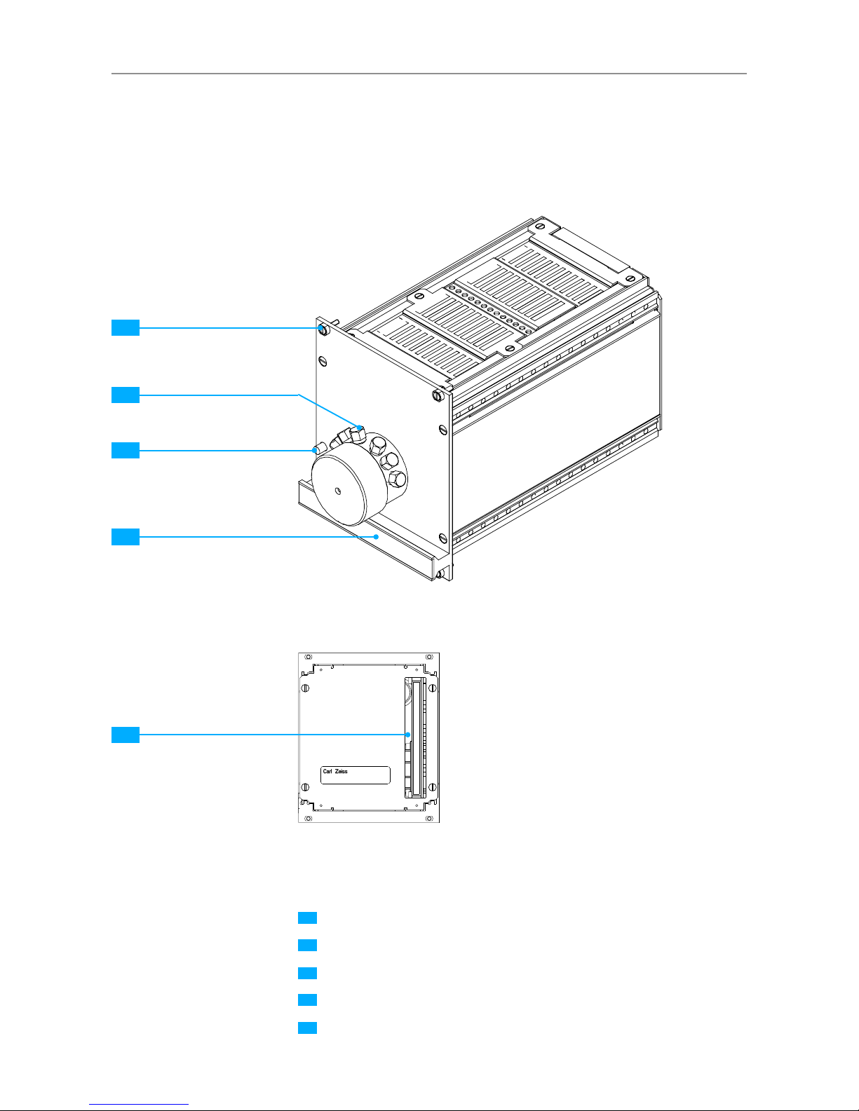
Fig. 1 19-inch housing,
front
ON/OFF switch
Interface for configuring IP address, gateway address and subnet mask
via null modem cable (9-pin D-SUB port, RS 232)
ECCU
Ethernet port (10/100)
64-pin connector for electrical connection of up to four 14 TE spectrometer cassettes and one lamp cassette (right)
1
2
3
4
5
1
2
4 53
3.2.3 Overview
Note
The IP address can also be changed via ethernet once a connection
is established. The default address is 192.168.0.100.
Page 17

17
MCS 600 | User Manual
MCS 600
3.2.4 Specifications
Designation Description
Power connection 100 – 240 V AC, 50/60 Hz
Power consumption < 100 VA (depending on component
configuration)
Fuses 2 x T2 A/H
Protection class IP 20
Fig. 2 19-inch housing, rear
6 7 8 149 13121110
Power plug
Fuse drawer
12 V DC for protective housing fan (not intended to be connected by the customer)
Fan
I
2
C bus, 9-pin D-SUB port (for customer service only)
Interface for configuring IP address (9-pin D-SUB port, RS 232)
37-pin D-SUB port for 16 x IN/OUT (for industrial use, shielded)
32-pin port for 16 x IN/OUT (for laboratory use, unshielded)
24 V connector 4 x GND (short-circuit proof, limited current)
6
7
8
9
10
11
12
13
14
Page 18

18
MCS 600 | User Manual
MCS 600
3.2.5 IN/OUT configuration
Fig. 3 19-inch housing,
IN/OUT configuration
IN 0
IN 1
OUT 7
NC
NC
Aux 24 V
IN 0
IN 1
IN 2
IN 3
IN 4
IN 5
IN 6
IN 6
OUT 0
OUT 1
OUT 2
OUT 3
OUT 4
OUT 5
OUT 6
OUT 7
Aux 24 V
Aux 24 V
Aux 24 V
Aux 24 V
GND
GND
GND
GND
IN 0 to 3 Aux 24 V
OUT 0GND
S1 Relay
GND
GND
1
1
17
16
4
1
Trigger IN Trigger OUT
32
8
5
GND
GND
GND
NC
NC
GND
Note
In this version, only IN 0 through IN 5 and OUT 0 through OUT 7 can be
used.
Warning
Maximum load: 24 V DC: 800 mA
Maximum load: OUT 0 through 7: 100 mA each
Only connect Trigger IN to bounce-free and potential-free contacts.
Overload may cause the system to reset!
Page 19

19
MCS 600 | User Manual
MCS 600
Fig. 4 28 TE spectrometer
cassettes occupy two slots. The
cassette in slots 1 and 2 uses
the connectors on slot 2.
Fig. 5 Designation of the slots
for 14 TE spectrometer cassettes
(for 9.5 and 14-inch analog
housings)
ECCU SLOT 1 SLOT 2 SLOT 3 SLOT 4 LAMPENSLOT
ECCU SLOT 1 SLOT 2 SLOT 3 SLOT 4 LAMPENSLOT
ECCU SLOT 2 SLOT 3 SLOT 4 LAMPENSLOT
3.2.6 Labeling of slots
If you intend to initiate measurements using an external trigger, please note the
following corresponding slots and trigger inputs.
SLOT 1 SLOT 2 SLOT 3 SLOT 4
IN 0 IN 1 IN 2 IN 3
Page 20

20
MCS 600 | User Manual
MCS 600
3.2.7 Connecting the system
1. Connect the power cable on the rear side of the housing
6
and
insert it
into the power socket.
2. Connect your PC's ethernet cable to the ethernet port on the front side of
the housing.
4
3. The 37-pin D-SUB port for 16 x IN/OUT (for industrial use, shielded)
12
and
the 32-pin port for 16 x IN/OUT (for laboratory use, unshielded) 13 are designed to establish connections with external digital interfaces (e.g. external
triggers, remote controls).
4. Turn on your PC and launch the program.
5. Turn on the system. The LED
1
will illuminate green when the device is
ready to be used.
3.2.8 Replacing slide-in cassettes
Please ensure that the system is disconnected before inserting/removing slide-in
cassettes.
1. On the ECCU
3
, set the switch 1 to the position in which all LEDs are
off, then disconnect the device from the power supply and remove the cable
and/or light guide.
2. Loosen the securing screws on the front of the cassette and pull out the
cassette.
3. Place the new cassette on the module support and slide it into the housing
until you feel it snap into place.
4. Tighten the cassette firmly with the securing screws and reconnect the cables
and/or light guides.
5. Plug in the power cable and turn the device on.
Page 21

21
MCS 600 | User Manual
MCS 600
Fig. 6 Changing fuses
Power plug
Drawer
Fuse
Fuse holders
6
7
15
16
6
16
7
15
3.2.9 Changing fuses
Only use the fuse types specified in the "Specifications" section. Shorting, bridging or the use of temporary fuses is not permitted.
Note
If the fuses blow out frequently, please contact customer service. The
address can be found on page 2 of this document.
1. Turn the device off and disconnect the power plug.
2. Open the fuse drawer
7
.
3. Pull the fuse holder(s)
16
out and remove the defective fuse(s).
15
4. Insert the new T2 A/H fuse(s), slide the fuse holder(s) back into place and
close the drawer.
5. Plug in the device again and turn it on.
3.2.10 Spare parts
Designation Cat. no.
2 fuses, T2 A/H 000000-0499.204
Page 22

22
MCS 600 | User Manual
MCS 600
Page 23

23
MCS 600 | User Manual
MCS 600
3.3 MCS 601 UV-NIR spectrometer cassette
3.3.1 Overview
Fastening screws
SMA connector
Handle rail (for removing the cassette)
LED BUSY
LED TRIGGER
LED POWER
LED ERROR
LED SETTLING
64-pin connector for electrically connecting slide-in cassettes
(example corresponds to a 28 TE unit)
1
2
3
4
5
6
7
8
9
3
1
4
5
6
7
8
2
9
Fig. 8 MCS 601 UV-NIR spectrometer cassette,
rear view
Fig. 7 MCS 601 UV-NIR
spectrometer cassette,
front view
Page 24

24
MCS 600 | User Manual
MCS 600
3.3.2 Operating notes
Five LEDs are installed on the front of the MCS 601 UV-NIR spectrometer cassette. During operation, the specified LED will light up green (BUSY)
4
without
disrupting the saving of spectra (with short integration times, the LED will light up
constantly). The LED labeled TRIGGER 5 will flash yellow
if the measurement is triggered by the hardware. The LED labeled POWER 6 will
light up green if the cassette is switched on. In the event of a cassette error, the
red LED labeled ERROR 7 will light up. If the spectrometer cassette is switched
on, first the yellow LED labeled SETTLING 8 will light up, and will stop when the
cassette is ready to be measured.
If the LEDs do not light up as intended, a failure has occurred, and the slide-in
cassette must be replaced.
3.3.3 Changing the spectrometer cassette
Please ensure that the system is disconnected before inserting/removing slide-in
cassettes.
1. On the ECCU, set the switch to the position in which all LEDs are off, then
disconnect the device from the power supply and remove the cable and/or
light guide.
2. Loosen the fastening screws
1
on the front of the cassette and pull out the
cassette.
3. Place the new cassette on the module support and slide it into the housing
until you feel it snap into place.
4. Tighten the cassette firmly with the securing screws and reconnect the cable
and/or light guide.
5. Plug in the power cable and turn the device on.
Note
Submit defective slide-in cassettes to our Customer Service team for
repair. The address can be found on page 2 of this document.
Page 25

25
MCS 600 | User Manual
MCS 600
3.4 MCS 611 NIR 2.2 spectrometer cassette
3.4.1 Overview
Fastening screws
SMA connector
Handle rail (for removing the cassette)
LED BUSY
LED TRIGGER
LED POWER
LED ERROR
LED SETTLING
LED TEMP
64-pin connector for electrically connecting slide-in cassettes
1
2
3
4
5
6
7
8
9
10
Fig. 9 MCS 611 NIR 2.2
spectrometer cassette,
front view
Fig. 10 MCS 611 NIR 2.2
spectrometer cassette,
rear view
3
1
4
5
6
7
8
9
2
10
BUSY
TRIGGER
POWER
ERROR
SETTL
TEMP
(example corresponds to a cooled 14 TE unit)
Page 26

26
MCS 600 | User Manual
MCS 600
3.4.2 Operating notes
Six LEDs are installed on the front of the MCS 611 NIR 2.2 spectrometer cassette.
During operation, the specified LED will light up green (BUSY)
4
without disrupting the saving of spectra (with short integration times, the LED will light up
constantly). The LED labeled TRIGGER 5 will flash yellow
if the measurement is triggered by the hardware. The LED labeled POWER 6 will
light up green if the cassette is switched on. In the event of a cassette error, the
red LED labeled ERROR will light up. 7 If the spectrometer cassette is switched
on, first the yellow LED labeled SETTLING 8 will light up, and will stop when
the cassette is ready for measuring. Once the temperature LED turns off (orange
LED labeled TEMP
9
), the spectrometer is at the configured temperature and is
ready for measuring. If the LED does not turn off, the cooling is defective, and the
slide-in cassette must be replaced. If the LEDs do not light up as intended, a failure has occurred, and the slide-in cassette must be replaced.
3.4.3 Changing the spectrometer cassette
Please ensure that the system is disconnected before inserting/removing slide-in
cassettes.
1. On the ECCU, set the switch to the position in which all LEDs are off, then
disconnect the device from the power supply and remove the cable and/or
light guide.
2. Loosen the fastening screws
1
on the front of the cassette and pull out the
cassette.
3. Place the new cassette on the module support and slide it into the housing
until you feel it snap into place.
4. Tighten the cassette firmly with the securing screws and reconnect the cable
and/or light guide.
5. Plug in the power cable and turn the device on.
Note
Submit defective slide-in cassettes to our Customer Service team for
repair. The address can be found on page 2 of this document.
Page 27

27
MCS 600 | User Manual
MCS 600
3.5 MCS 621 VIS II spectrometer cassette
3.5.1 Overview
Fastening screws
SMA connector
Handle rail (for removing the cassette)
LED BUSY
LED TRIGGER
LED POWER
LED ERROR
LED SETTLING
64-pin connector for electrically connecting slide-in cassettes
1
2
3
4
5
6
7
8
9
Fig. 11 MCS 621 VIS II
spectrometer cassette,
front view
Fig. 12 MCS 621 VIS II
spectrometer cassette, rear view
3
1
4
5
6
7
8
2
9
(example corresponds to an uncooled 14 TE unit)
Page 28

28
MCS 600 | User Manual
MCS 600
3.5.2 Operating notes
Five LEDs are installed on the front of the MCS 621 VIS II spectrometer cassette.
During operation, the specified LED will light up green (BUSY)
4
without disrupting the saving of spectra (with short integration times, the LED will light up
constantly). The LED labeled TRIGGER 5 will flash yellow
if the measurement is triggered by the hardware. The LED labeled POWER 6 will
light up green if the cassette is switched on. In the event of a cassette error, the
red LED labeled ERROR will light up.
7
If the spectrometer cassette is switched
on, first the yellow LED labeled SETTLING 8 will light up, and will stop when the
cassette is ready to be measured.
If the LEDs do not light up as intended, a failure has occurred, and the slide-in
cassette must be replaced.
3.5.3 Changing the spectrometer cassette
Please ensure that the system is disconnected before inserting/removing slide-in
cassettes.
1. On the ECCU, set the switch to the position in which all LEDs are off, then
disconnect the device from the power supply and remove the cable and/or
light guide.
2. Loosen the fastening screws
1
on the front of the cassette and pull out the
cassette.
3. Place the new cassette on the module support and slide it into the housing
until you feel it snap into place.
4. Tighten the cassette firmly with the securing screws and reconnect the cable
and/or light guide.
5. Plug in the power cable and turn the device on.
Note
Submit defective slide-in cassettes to our Customer Service team for
repair. The address can be found on page 2 of this document.
Page 29

29
MCS 600 | User Manual
MCS 600
3.6 SVS 600 electrical power supply cassette
3.6.1 Intended use
The SVS 600 electrical power supply cassette is responsible for providing electrical
power to optical probes such as the OMK Eclipse or the OFR-d8. The electrical
power supply cable is connected to the receptacle
2
on the front of the housing.
Fastening screws
Electrical power supply cable connection
ON/OFF switch
Handle rail
Interface for MCS 600 housing
1
2
3
4
5
Fig. 13 SVS 600 electrical power
supply cassette, front view
2
3
4
1
Fig. 14 SVS 600 electrical power
supply cassette, rear view
5
Page 30

30
MCS 600 | User Manual
MCS 600
Page 31

31
MCS 600 | User Manual
MCS 600
3.7 Lamp cassettes
3.7.1 Intended use
ZEISS lamp cassettes are highly stable light sources intended for use in spectroscopy. The cassettes are modular components and may only be used in MCS 600
system housings. The manufacturer must first be consulted before the cassettes
may be used for any other purpose. The lamp cassettes are specifically designed
to be used with flexible optical fibers and may only be used as such.
3.7.2 Operating notes
The lamp cassette must be fastened with the four fastening screws.
When the lamp is ready for use, the right LED on the ECCU controller will light up
green. The cassette is controlled by the MCS 600 housing and the software.
Warning
With the exception of changing lamps, no care or repair work may
be carried out on the lamp cassette by users themselves. Doing so
can seriously damage the device. Repairs may only be performed by
authorized ZEISS Service personnel.
3.7.3 Lamp cassette specifications
See https://www.zeiss.com/spectroscopy/products/spectrometer-systems/mcs-
600.html
Page 32

32
MCS 600 | User Manual
MCS 600
Page 33

33
MCS 600 | User Manual
MCS 600
3.8 BLX 600/SMA lamp cassette
3.8.1 Overview
Fastening screws
SMA connector
Handle rail
Interface for MCS 600 housing
1
2
3
4
Fig. 15 BLX 600/SMA lamp cassette
1
2
3
Fig. 16 BLX 600/SMA lamp cassette, rear view
4
Page 34

34
MCS 600 | User Manual
MCS 600
3.8.2 Safety information for BLX 600/SMA xenon lamp
Warning
The BLX 600/SMA xenon lamp contains electronic, electromechanical,
mechanical and optical components. These components require special
care when being transported and used. The ventilation slots on the rear
side of the housing must not be covered or obstructed.
Caution
Risk of explosion!
The information and safety guidelines provided by the lamp
manufacturer must be consulted before changing the lamp. The xenon
lamp's gas filling is highly pressurized even when the lamp is cold (10
bar at room temperature). The lamp must be allowed to cool for at
least 30 minutes before being changed. For your own safety, wear face
protection, a leather apron and cuffed leather gloves as protection
against shattering. Be sure to dispose of the used lamps appropriately.
Caution
Coherent radiation!
The xenon lamp emits light in the ultraviolet range! Do not look directly
into the beam path or expose your skin to it! Doing so will result in
injury to the eyes and skin. Please observe the relevant regulations
when handling UV light sources. Cover unused SMA connectors on the
lamp with caps.
Warning
The xenon lamp's ignition voltages are in the range of several 100 V.
These voltages are generated in and accumulate in the electronics. Do
not attempt to modify the internal electronics or wiring!
3.8.3 Spare parts for the BLX 600/SMA lamp cassette
Designation Cat. no.
Flash Bulb L4633-01 000000-0235-825
Page 35

35
MCS 600 | User Manual
MCS 600
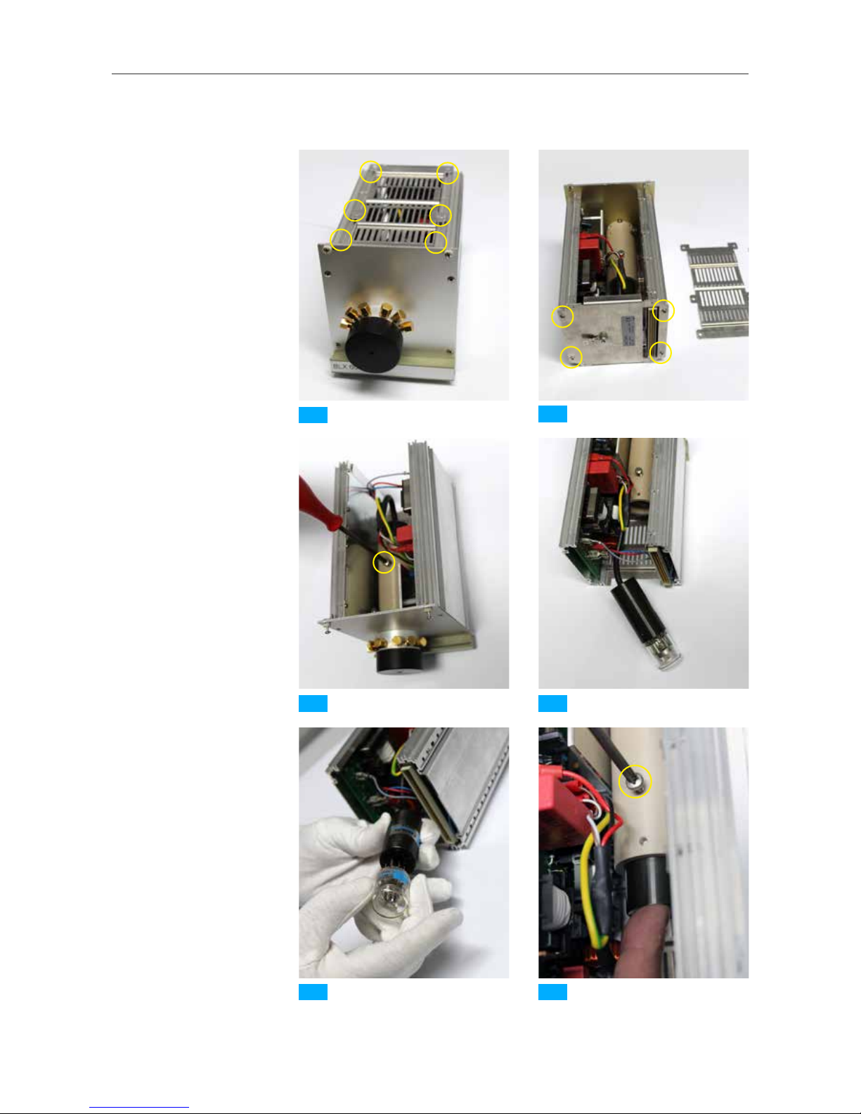
3.8.4 Changing the lamp
The cassette must be opened in order to change the lamp.
Warning
Xenon lamp is sensitive!
The slightest traces of dirt and grease on the glass body of the lamp
can impair the intensity and service life of the lamp. Use dust-free,
grease-free rubber gloves when changing the lamp.
Caution
Xenon lamp is hot!
Allow defective lamps to cool!
How to Implement …
1. Turn the spectrometer system off and disconnect it from the power supply.
2. Loosen the four fastening screws and pull the lamp cassette out of the
housing.
3. Loosen the six screws on the upper grill plate.
1
4. Remove the upper grill plate.
5. Loosen the four screws on the rear grill plate and remove the plate.
2
6. Loosen the locking screw.
3
7. Remove the lamp chimney from the tubular housing.
4
8. Remove the defective lamp from the holder and replace it with a new lamp.
5
9. Place the lamp chimney all the way back into the tubular housing and retigh-
ten the locking screw.
6
10. Reattach the upper and rear grill plates to the lamp cassette housing.
11. Slide the lamp cassette back into the housing and retighten the fastening
screws.
12. You can now reconnect the spectrometer system to the power supply and
turn it on.
Page 36
36
MCS 600 | User Manual
MCS 600
1
3 4
5 6
2
Fig. 17 BLX 600/SMA lamp replacement
Page 37
37
MCS 600 | User Manual
MCS 600
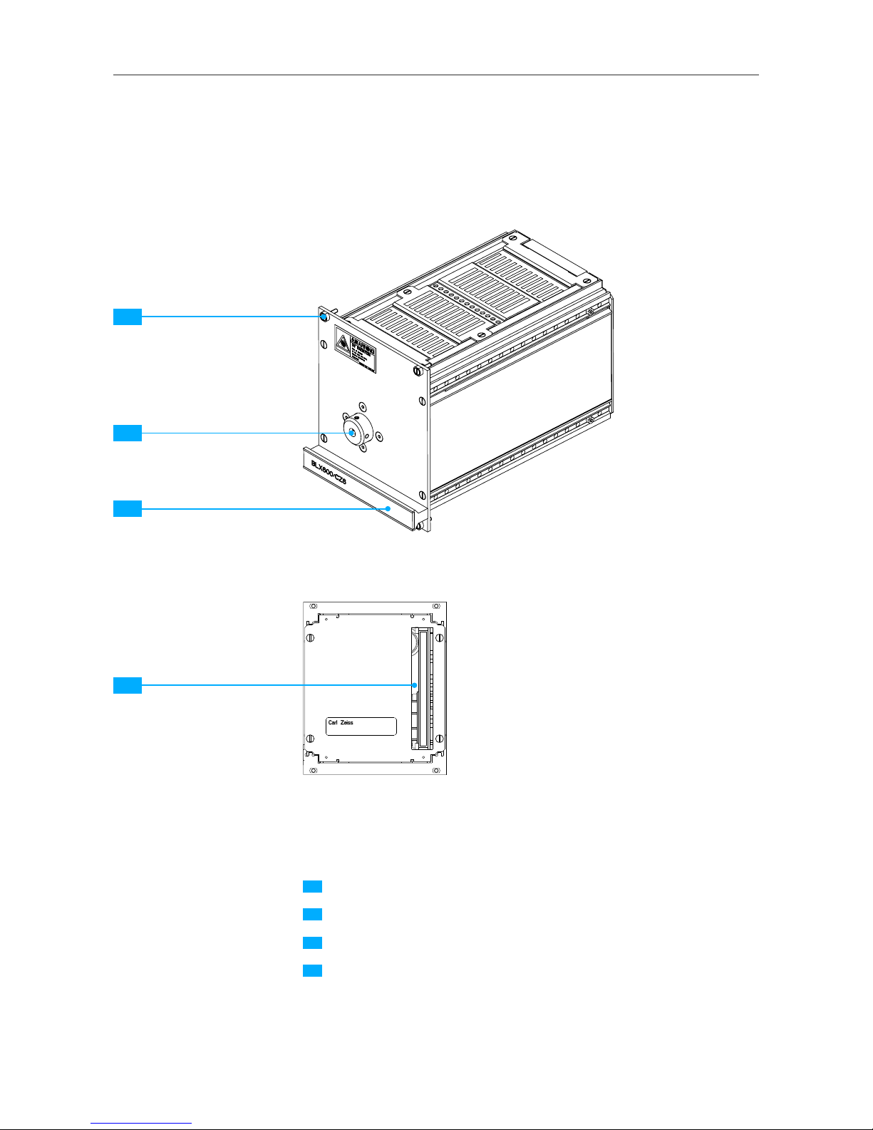
3.9 BLX 600/CZ6 lamp cassette
3.9.1 Overview
Fig. 18 BLX 600/CZ6 lamp cassette
1
2
3
Fig. 19 BLX 600/CZ6 lamp cassette, rear view
4
Fastening screws
Zeiss CZ6 connector
Handle rail
Interface for MCS 600 housing
1
2
3
4
Page 38

38
MCS 600 | User Manual
MCS 600
3.9.2 Safety information for BLX 600/CZ6 xenon lamp
Warning
The BLX 600/CZ6 xenon lamp contains electronic, electromechanical,
mechanical and optical components. These components require special
care when being transported and used. The ventilation slots on the rear
side of the housing must not be covered or obstructed.
Caution
Risk of explosion!
The information and safety guidelines provided by the lamp
manufacturer must be consulted before changing the lamp. The xenon
lamp's gas filling is highly pressurized even when the lamp is cold (10
bar at room temperature). The lamp must be allowed to cool for at
least 30 minutes before being changed. For your own safety, wear face
protection, a leather apron and cuffed leather gloves as protection
against shattering. Be sure to dispose of the used lamps appropriately.
Caution
Coherent radiation!
The xenon lamp emits light in the ultraviolet range! Do not look directly
into the beam path or expose your skin to it! Doing so will result in
injury to the eyes and skin. Please observe the relevant regulations
when handling UV light sources. Cover unused SMA connectors on the
lamp with caps.
Warning
The xenon lamp's ignition voltages are in the range of several 100 V.
These voltages are generated in and accumulate in the electronics. Do
not attempt to modify the internal electronics or wiring!
3.9.3 Spare parts for the BLX 600/CZ6 lamp cassette
Designation Cat. no.
Flash Bulb L4633-01 000000-235-825
Page 39

39
MCS 600 | User Manual
MCS 600
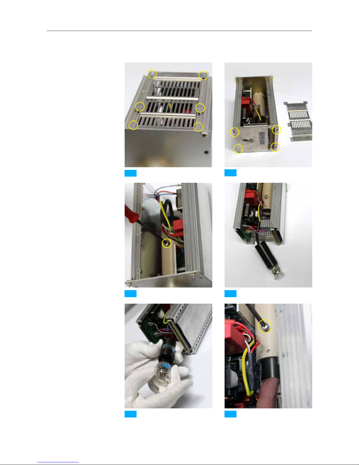
3.9.4 Changing the lamp
The cassette must be opened in order to change the lamp.
Warning
Xenon lamp is sensitive!
The slightest traces of dirt and grease on the glass body of the bulb can
impair the intensity and service life of the lamp. Use dust-free, greasefree rubber gloves when changing the lamp.
Caution
Xenon lamp is hot!
Allow defective lamps to cool!
How to Implement …
1. Turn the spectrometer system off and disconnect it from the power supply.
2. Loosen the four fastening screws and pull the lamp cassette out of the
housing.
3. Loosen the six screws on the upper grill plate.
1
4. Remove the upper grill plate.
5. Loosen the four screws on the rear grill plate and remove the plate.
2
6. Loosen the locking screw.
3
7. Remove the lamp chimney from the tubular housing.
4
8. Remove the defective lamp from the holder and replace it with a new lamp.
5
9. Place the lamp chimney all the way back into the tubular housing and retigh-
ten the locking screw.
6
10. Reattach the upper and rear grill plates to the lamp cassette housing.
11. Slide the lamp cassette back into the housing and retighten the fastening
screws.
12. You can now reconnect the spectrometer system to the power supply and
turn it on.
Page 40

40
MCS 600 | User Manual
MCS 600
1
3 4
5 6
2
Fig. 20 BLX 600/CZ6 lamp replacement
Page 41

41
MCS 600 | User Manual
MCS 600
3.10 BLX 606 lamp cassette
3.10.1 Overview
Fastening screws
SMA connectors
Handle rail
Interface for MCS 600 housing
1
2
3
4
Fig. 21 BLX 606 lamp cassette
2
3
1
Fig. 22 BLX 606 lamp cassette, rear view
4
Page 42

42
MCS 600 | User Manual
MCS 600
3.10.2 Safety information for BLX 606 xenon lamp
Warning
The BLX 606 xenon lamp contains electronic, electromechanical,
mechanical and optical components. These components require special
care when being transported and used. The ventilation slots on the rear
side of the housing must not be covered or obstructed.
Caution
Risk of explosion!
The information and safety guidelines provided by the lamp
manufacturer must be consulted before changing the lamp. The xenon
lamp's gas filling is highly pressurized even when the lamp is cold (10
bar at room temperature). The lamp must be allowed to cool for at
least 30 minutes before being changed. For your own safety, wear face
protection, a leather apron and cuffed leather gloves as protection
against shattering. Be sure to dispose of the used lamps appropriately.
Caution
Coherent radiation!
The xenon lamp emits light in the ultraviolet range! Do not look directly
into the beam path or exposure your skin to it! Doing so will result in
injury to the eyes and skin. Please observe the relevant regulations
when handling UV light sources. Cover unused SMA connectors on the
lamp with caps.
Warning
The xenon lamp's ignition voltages are in the range of several 100 V.
These voltages are generated in and accumulate in the electronics. Do
not attempt to modify the internal electronics or wiring!
3.10.3 Spare parts for the BLX 606 lamp cassette
Designation Cat. no.
Flash Bulb L4633-01 000000-1345-781
Page 43
43
MCS 600 | User Manual
MCS 600
3.10.4 Changing the lamp
The cassette must be opened in order to change the lamp.
Warning
Xenon lamp is sensitive!
The slightest traces of dirt and grease on the glass body of the lamp
can impair the intensity and service life of the lamp. Use dust-free,
grease-free rubber gloves when changing the lamp.
Caution
Xenon lamp is hot!
Allow defective lamps to cool!
How to Implement …
1. Turn the spectrometer system off and disconnect it from the power supply.
2. Loosen the four fastening screws and pull the lamp cassette out of the
housing.
3. Loosen the six screws on the upper grill plate.
1
4. Remove the upper grill plate.
5. Loosen the four screws on the rear grill plate and remove the plate.
2
6. Loosen the locking screw.
3
7. Remove the lamp chimney from the tubular housing.
4
8. Remove the defective lamp from the holder and replace it with a new lamp.
5
9. Place the lamp chimney all the way back into the tubular housing and retigh-
ten the locking screw.
6
10. Reattach the upper and rear grill plates to the lamp cassette housing.
11. Slide the lamp cassette back into the housing and retighten the fastening
screws.
12. You can now reconnect the spectrometer system to the power supply and
turn it on.
Page 44
44
MCS 600 | User Manual
MCS 600
1
3 4
5 6
2
Fig. 23 BLX 606 lamp replacement
Page 45

45
MCS 600 | User Manual
MCS 600
3
3.11 CLD 600 lamp cassette
3.11.1 Overview
Fastening screws
SMA connector
Handle rail
Interface for MCS 600 housing
1
2
3
4
Fig. 24 CLD 600 lamp cassette
2
1
3
Fig. 25 CLD 600 lamp cassette, rear view
4
Page 46

46
MCS 600 | User Manual
MCS 600
3.11.2 Operating notes
Note
The spectral emission radiation characteristic of the deuterium lamp
will change during the warm-up phase. A minimum warm-up time
of approx. 30 minutes must therefore be observed as the emitter is
then able to achieve a stable operating condition. For very precise
measurements, a warm-up time of at least 60 minutes is necessary so
that the optical and mechanical components of the bulb can achieve a
constant working temperature.
Note
Turning the lamp on and off frequently can considerably reduce the
emitter's average life span. The lamp should therefore not be turned off
if work is halted for relatively short periods of time.
3.11.3 Safety information for CLD 600 lamp cassette
Caution
UV radiation!
The deuterium lamp emits light in the ultraviolet range! Do not look
directly into the beam path! Doing so will result in injury to the eyes.
Please observe the relevant regulations when handling UV light sources.
3.11.4 Spare parts for CLD 600 lamp cassette
Designation Cat. no.
Deuterium lamp for CLD 600 000000-1446-440
Page 47

47
MCS 600 | User Manual
MCS 600
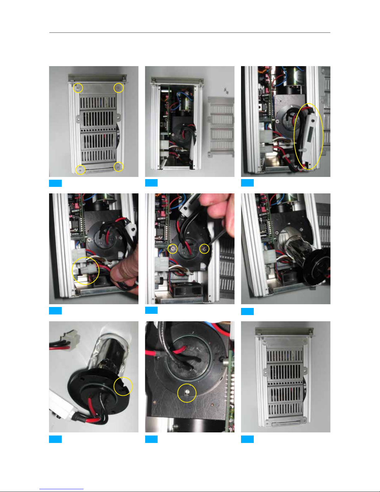
3.11.5 Changing the lamp
The cassette must be opened in order to change the lamp.
Warning
Deuterium lamp is sensitive!
The slightest traces of dirt and grease on the glass body of the lamp
can impair the intensity and service life of the lamp. Use dust-free,
grease-free rubber gloves when changing the lamp.
Caution
Deuterium lamp is hot!
Allow defective lamps to cool!
How to Implement …
1. Turn the device off and disconnect the power plug. Loosen the four fastening
screws and pull the lamp cassette out of the housing.
2. Loosen the four screws on the grating on the underside of the cassette and
remove the grating.
1
3. The lamp socket should now be visible.
2
4. Lift the connection cable with the operating hours meter.
3
5. Disconnect the connection plug from the circuit board.
4
6. Loosen the locking screws on the lamp socket and remove them.
5
7. Remove the deuterium lamp from the lamp chimney. Do not touch the lamp
body with your bare hands!
6
8. Lamp with guide groove.
7
9. Install the new lamp. Pay attention the guide groove to make sure you set
the lamp in the correct direction. Reattach the locking screws and tighten
them.
8
10. Place the cable with the operating hours meter back in the housing and
reattach the cover plate. Slide the lamp cassette back into the housing and
retighten the fastening screws.
9
11. Reconnect the device to the power supply and turn it on.
Note
To achieve accurate measurements, the new deuterium lamp must first
be allowed to burn for 14 hours.
Page 48
48
MCS 600 | User Manual
MCS 600
1
3
4
6
5
7 8 9
2
Fig. 26 CLD 600 lamp replacement
Page 49

49
MCS 600 | User Manual
MCS 600
3
3.12 CLH 600 lamp cassette
3.12.1 Overview
Fastening screws
SMA connector
Handle rail
ON/OFF shutter
Interface for MCS 600 housing
1
2
3
4
5
Fig. 27 CLH 600 lamp cassette
2
1
3
4
Fig. 28 CLH 600 lamp cassette, rear view
5
Page 50
50
MCS 600 | User Manual
MCS 600
3.12.2 Operating notes
The shutter can be opened and closed directly on the CLH 600.
4
The button
will light up yellow if the shutter is off and the light from the halogen bulb is
available.
Note
The spectral emission radiation characteristic of the halogen bulb
will change during the warm-up phase. A minimum warm-up time
of approx. 10 minutes must therefore be observed as the emitter is
then able to achieve a stable operating condition. For very precise
measurements, a warm-up time of 60 minutes is necessary so that the
optical and mechanical components of the bulb can achieve a constant
working temperature.
3.12.3 Safety information for CLH 600 lamp cassette
Caution
Coherent radiation!
Never look directly into the measuring beam. Coherent radiation can
lead to eye injuries (e.g. conjunctivitis). Please observe the relevant
regulations when handling light sources of this type.
3.12.4 Spare parts for CLH 600 lamp cassette
Designation Cat. no.
Halogen lamp 5V/1.8A for CLH 600 000000-1446-069
Page 51

51
MCS 600 | User Manual
MCS 600
3.12.5 Changing the lamp
The cassette must be opened in order to change the lamp.
Warning
Halogen lamp is sensitive!
The slightest traces of dirt and grease on the glass body of the lamp
can impair the intensity and service life of the lamp. Use dust-free,
grease-free rubber gloves when changing the lamp.
Caution
Halogen lamp is hot!
Allow defective lamps to cool!
How to Implement …
1. Turn the device off and disconnect the power plug.
2. Loosen the four fastening screws and pull the lamp cassette out of the
housing.
3. Loosen the 4 screws on the upper grating and remove the grating.
1
4. Cut the cable tie, if necessary.
2
5. Remove the plug connector.
3
6. Loosen the knurled screw.
4
Warning
Do not touch the lens of the new halogen lamp!
7. Install the new lamp with the black mark facing upward and retighten the
knurled screw.
5
8. Then, reconnect the cable (reverse polarity protection).
6
You do not need to reattach the cable tie.
9. Reattach the upper grating and tighten the screws.
10. Insert the lamp cassette again and tighten the screws.
11. Reconnect the device to the power supply and turn it on.
Page 52

52
MCS 600 | User Manual
MCS 600
1
3 4
5 6
2
Fig. 29 CLH 600 lamp replacement
Page 53

53
MCS 600 | User Manual
MCS 600
3.13 CLH 600 F lamp cassette
3.13.1 Overview
Fastening screws
SMA connector
Handle rail
ON/OFF shutter
Interface for MCS 600 housing
1
2
3
4
5
Fig. 30 CLH 600 F lamp cassette
3
1
2
4
Fig. 31 CLH 600 F lamp cassette, rear view
5
Page 54
54
MCS 600 | User Manual
MCS 600
3.13.2 Operating notes
The shutter can be opened and closed directly on the CLH 600 F.
4
The button
will light up yellow if the shutter is off and the light from the halogen bulb is
available.
Note
The spectral emission radiation characteristic of the halogen bulb
will change during the warm-up phase. A minimum warm-up time
of approx. 10 minutes must therefore be observed as the emitter is
then able to achieve a stable operating condition. For very precise
measurements, a warm-up time of 60 minutes is necessary so that the
optical and mechanical components of the bulb can achieve a constant
working temperature.
3.13.3 Safety information for CLH 600 F lamp cassette
Caution
Coherent radiation!
Never look directly into the measuring beam. Coherent radiation can
lead to eye injuries (e.g. conjunctivitis). Please observe the relevant
regulations when handling light sources of this type.
3.13.4 Spare parts for CLH 600 F lamp cassette
Designation Cat. no.
Halogen lamp 5V/1.8A for CLH 600 000000-1446-069
Page 55

55
MCS 600 | User Manual
MCS 600
3.13.5 Changing the lamp
The cassette must be opened in order to change the lamp.
Warning
Halogen lamp is sensitive!
The slightest traces of dirt and grease on the glass body of the lamp
can impair the intensity and service life of the lamp. Use dust-free,
grease-free rubber gloves when changing the lamp.
Caution
Halogen lamp is hot!
Allow defective lamps to cool!
How to Implement …
1. Turn the device off and disconnect the power plug.
2. Loosen the four fastening screws and pull the lamp cassette out of the
housing.
3. Loosen the 4 screws on the upper grating and remove the grating.
1
4. Cut the cable tie, if necessary.
2
5. Remove the plug connector.
3
6. Loosen the knurled screw.
4
Warning
Do not touch the lens of the new halogen lamp!
7. Install the new lamp with the black mark facing upward and retighten the
knurled screw.
5
8. Then, reconnect the cable (reverse polarity protection).
6
You do not need to reattach the cable tie.
9. Reattach the upper grating and tighten the screws.
10. Insert the lamp cassette again and tighten the screws.
11. Reconnect the device to the power supply and turn it on.
Page 56

56
MCS 600 | User Manual
MCS 600
1
3 4
5 6
2
Fig. 32 CLH 600 F lamp replacement
Page 57
57
MCS 600 | User Manual
MCS 600
3.14 CLH 606 A lamp cassette
3.14.1 Overview
Fastening screws
SMA connectors
Handle rail
ON/OFF shutter
Interface for MCS 600 housing
1
2
3
4
5
Fig. 33 CLH 606 A lamp cassette
2
1
3
4
Fig. 34 CLH 606 A lamp cassette, rear view
5
Page 58

58
MCS 600 | User Manual
MCS 600
3.14.2 Operating notes
The lamp can be opened and closed directly on the CLH 606 A.
4
The button
will light up yellow if the lamp is on and the light from the halogen lamp is
available.
Note
The spectral emission radiation characteristic of the halogen bulb
will change during the warm-up phase. A minimum warm-up time
of approx. 10 minutes must therefore be observed as the emitter is
then able to achieve a stable operating condition. For very precise
measurements, a warm-up time of 60 minutes is necessary so that the
optical and mechanical components of the bulb can achieve a constant
working temperature.
3.14.3 Safety information for CLH 606 A lamp cassette
Caution
Coherent radiation!
Never look directly into the measuring beam. Coherent radiation can
lead to eye injuries (e.g. conjunctivitis). Please observe the relevant
regulations when handling light sources of this type.
3.14.4 Spare parts for CLH 606 A lamp cassette
Designation Cat. no.
Halogen lamp 10V/1.8A for CLH 606 000000-1446-136
Page 59

59
MCS 600 | User Manual
MCS 600
3.14.5 Changing the lamp
The cassette must be opened in order to change the lamp.
Warning
Halogen lamp is sensitive!
The slightest traces of dirt and grease on the glass body of the lamp
can impair the intensity and service life of the lamp. Use dust-free,
grease-free rubber gloves when changing the lamp.
Caution
Halogen lamp is hot!
Allow defective lamps to cool!
How to Implement …
1. Turn the device off and disconnect the power plug.
2. Loosen the four fastening screws and pull the lamp cassette out of the
housing.
3. Loosen the 4 screws on the upper grating and remove the grating.
1
4. Loosen the knurled screw and carefully remove the lamp from the holder.
2 3
5. Disconnect the lamp connector.
4
Warning
Do not touch the lens of the new halogen bulb!
6. Install the new lamp
5
and slightly tighten the knurled screw again.
7. Then, reconnect the cable (reverse polarity protection).
8. Reattach the upper grating and tighten the screws.
9. Insert the lamp cassette again and tighten the screws.
10. Reconnect the device to the power supply and turn it on.
Page 60

60
MCS 600 | User Manual
MCS 600
1
3 4
5
2
Fig. 35 CLH 606 A bulb replacement
Page 61
61
MCS 600 | User Manual
MCS 600 Network Connection
MCS 600
4 MCS 600 Network Connection
We recommend using a CAT 6 S/FTP patch cable for establishing network connections with the MCS 600.
Note
If the device is connected directly to an older ethernet adapter without
auto MDI-X, a crossover patch cable must be used.
Connections are made via TCP and port 7890. Please make sure your firewall
settings are configured accordingly.
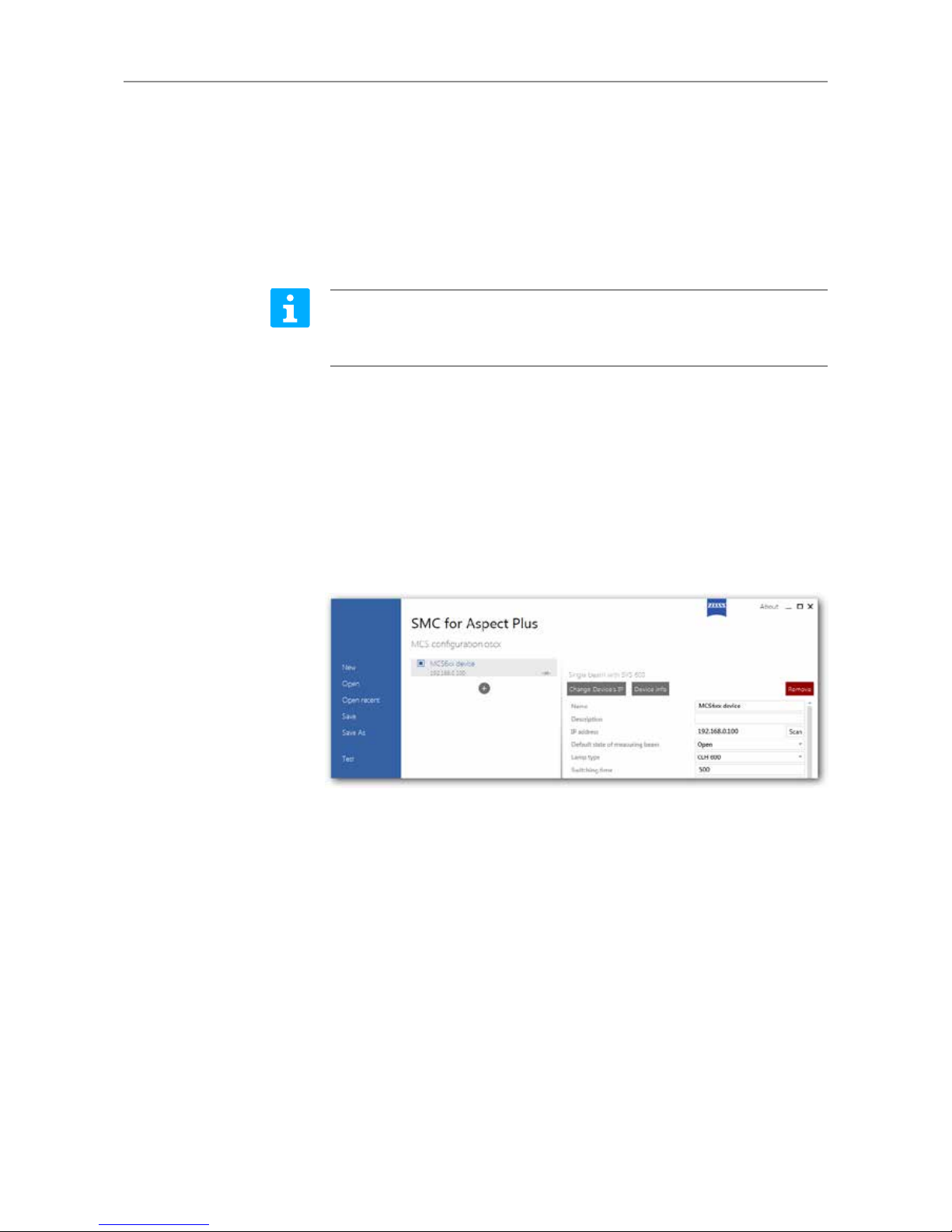
If your network supports UDP commands, you can search the network for the address of a connected device. To do this, you can use the SMC program included
in the standard software packages (e.g. Aspect plus and InProcess). In the righthand section of the SMC program, there is an input field where you can enter
the IP address of the device you wish to use. Next to the input field is a button
labeled "Scan".
Page 62
62
MCS 600 | User Manual
MCS 600 Network Connection
MCS 600
4.1 Manually configuring the device network (no
DHCP server)
The spectrometer and the PC's network adapter must have different IP addresses
within the same IP address range. This section describes how to modify the address of the measuring PC's network adapter in order to establish a connection
with an MCS 600 with factory settings. Administrator rights are needed to change these settings. If you do not have administrator rights, contact your administrator.
The following information applies to Windows 7:
1. Press the Windows button and enter "Network connections".
2. Select "View network connections".
3. Double-click on the network adaptor you want to connect to the MCS 600.
Note
If you have multiple network adapters, you can identify the correct
adapter by disconnecting and reconnecting the network cable several
times. This will change the adapter's connection status.
4. In the dialog window, select "Internet Protocol Version 4 (TCP/IPv4)".
5. Click the "Properties" button.
Note
Before changing the settings on your PC's network adapter, make a
note of the original settings so that you can reset them at a later point
in time.
6. The following settings should be used to enable your measuring computer's
network adapter to communicate with an MCS 600 with factory settings.
Use the following IP address:
IP address: 192.168.0.x where x is a number ranging from 1 to 254
(except for 100)
Subnet mask: 255.255.255.0
Note
Alternatively, you can use the following settings
to get a larger address range:
IP address: 192.168.y.z where y.z is a number ranging from 0.1 to 255.254
(except for 0.100) Subnet mask: 255.255.0.0
If necessary, use a second network adapter for your company's network and
connecting to the Internet.
Page 63

63
MCS 600 | User Manual
MCS 600 Network Connection
MCS 600
4.2 Embedding the MCS 600 in a company network
with a DHCP server
Request a fixed IP address, subnet mask and gateway for the MCS 600 from your
administrator. Configure your settings using these values in accordance with one
of the methods provided in section 4.3.
Then, configure your measuring computer's network adapter as follows: Administrator rights are needed to change these settings. If you do not have administrator rights, contact your administrator.
The following information applies to Windows 7:
1. Press the Windows button and enter "Network connections".
2. Select "View network connections".
3. Double-click on the network adaptor you want to connect to the MCS 600.
Note
If you have multiple network adapters, you can identify the correct
adapter by disconnecting and reconnecting the network cable several
times. This will change the adapter's connection status.
4. In the dialog window, select "Internet Protocol Version 4 (TCP/IPv4)".
5. Click the "Properties" button.
Note
Before changing the settings on your PC's network adapter, make a
note of the original settings so that you can reset them at a later point
in time.
6. Select "Obtain an IP address automatically".
Page 64

64
MCS 600 | User Manual
MCS 600 Network Connection
MCS 600
4.3 Changing the MCS 600's IP address
Upon delivery, the device's settings are configured as follows:
IP address: 192.168.0.100
Subnet mask: 255.255.0.0
Gateway: 0.0.0.0
There are three ways to change these settings:
1. If an ethernet connection has been established (the connection icon is visible
next to the device name), the SMC program can be used to change the IP
address ("Change Device‘s IP").
2. The IP address and subnet mask can also be changed with the "ethconf" pro-
gram, regardless of the ethernet adapter's configuration. This program uses
UDP communication and is included with the OSIS SDK. Contact ZEISS customer service for more information.
3. The IP address, subnet mask and gateway can be changed in a hyperterminal
shortly after restarting the device. To do this, the MCS 600 must be connected
via the ECCU's D-Sub port (see figure 1 in section 3.2) to the COM port on a
computer using a null modem cable. Contact ZEISS customer service for help.
Warning
The MCS6xx cannot obtain an IP address via DHCP.
Page 65

65
MCS 600 | User Manual
MCS 600 Network Connection
MCS 600
Configured IP addresses (notes)
Factory settings IP address: 192.168.0.100
Subnet mask: 255.255.0.0
Gateway: 0.0.0.0
Your set IP address
Changed on:
_____ . _____ . _______
IP address:
Subnet mask:
Gateway:
Your set IP address
Changed on:
_____ . _____ . _______
IP address:
Subnet mask:
Gateway:
Your set IP address
Changed on:
_____ . _____ . _______
IP address:
Subnet mask:
Gateway:
Your set IP address
Changed on:
_____ . _____ . _______
IP address:
Subnet mask:
Gateway:
Page 66

66
MCS 600 | User Manual
MCS 600 Network Connection
MCS 600
Page 67

67
MCS 600 | User Manual
Maintenance and Care
MCS 600
5 Maintenance and Care
5.1 Care
Care of the devices is limited to the following operations:
Warning
Prior to cleaning, the devices must be disconnected from the power
supply. Ensure that no cleaning fluids enter the devices.
The surfaces of the devices must be cleaned with commercially available cleaning
agents (not solutions!). In exceptional cases dirt which is difficult to remove can
be carefully treated with pure benzene or petroleum ether.
Caution
Please observe the legal regulations governing the handling of
inflammable liquids and solvents.
5.2 Maintenance
Only the parts listed in the respective sections under "Spare parts" may be used
for maintenance of the system. These parts can be requested by contacting
customer service and providing the order number.
5.3 Service
All repairs of mechanical, optical or electronic components inside the system may
only be performed by ZEISS customer service or specially authorized personnel.
To ensure that your system remains perfectly functional and optically configured
for a long time, we recommend concluding a service/maintenance contract with
ZEISS. For subsequent orders or if service is required, please contact your local
ZEISS representative.
Page 68

68
MCS 600 | User Manual
Maintenance and Care
MCS 600
 Loading...